Embed Size (px)
Citation preview

RL-TR-93-149 -- 948Final Technical ReportJuly 199311io i3ý
OPTICAL SWITCHEVALUATION SUPPORT
Syracuse University
Joseph Chaiken
":* 0
APPROVED FOR PUBLIC RELEASE;D/STRIBUTION UN/IMI/TED.
-- wDTIC
1993
Rome LaboratoryAir Force Materiel Command
Griffiss Air Force Base, New York
93 10 IS )35
J u -- l ,, - I -- i - ' 0

This report has been reviewed by the Rome Laboratory Public Affairs Office(PA) and is releasable to the National Technical Information Service (NTIS). AtNTIS it will be releasable to the general public, including foreign nations.
RL-TR-93-149 has been reviewed and is approved for publication.
APPROVED:/ -'"
OSMANProject Engineer
/ 0/
FOR THE COMMANDER: /7 / '
JAMES W. YOUNGBERG, Lt Col, USAFDeputy DirectorSurveillance & Photonics Directorate
If your address has changed or if you wish to be removed from the Rome Laboratorymailing list, or if the addressee is no longer employed by your organization,please notify RL ( OCPB ) Griffiss AFB NY 13441. This will assist us in maintaininga current mailing list.
Do not return copies of this report unless contractual obligations or notices on aspecific document require that it be returned.
• • • •• • •0
0
REPORT DOCUMENTATION PAGE I NV07o4lo1 8pt,"c 8600 baaudf ls mIIIidahlfto~ a " to 0q 1 rem PW .mi ouitu, are t iimet hocw MdmgVu6rwv dI swAc."
eokakdtftiiiiiiin eimftxk t 0 1n Hamftnm~~ Swv~ftOkWugftf lftimhf Op mu Rti 1215 Jdfosm'O.4ot . 51'*5...s4,a .,git~ VA 4=-tm•= oarn t.O .mummit == Pm aI A0,,t.sPtag~el •7m. whUWa oC 2O
i. AGENCY USE ONLY UAave 6131k Z2 REPORT DATE 3. REPORT TYPE AND DATE$ COVEREDJuly 1993 Final Feb 91 - Feb 92
4. TITLE AND SUBTITLE 5. FUNDING NUMBERSOPTICAL SWITCH EVALUATION SUPPORT C - F30602-91-D-0001,
Task 0003PE - 52702F
.AUTHORM3 PR - 4600Joseph Chaiken TA - P3
WJ_ - PD7. PERFORING ORGANZATION NAME() AND ADORESS(ES) 8. PERFORMING ORGANIZATION
Syracuse University REPORT NUMBERDepartment of Chemistry N/ASyracuse NY 13244-4100
9. SPONSORINGIMONITORING AGENCY NAME(S) AND ADDRESS(ES) 10L SPONSORING/MONITORINGRome Laboratory (CCPB) AGENCY REPORT NUMBER25 Electronic Pkv RL-TR-93-149Griffiss AFB NY 13441-4515
"11. SUPPLEMENTARY NOTES
Rome Laboratory Proiect Engineer: Joseph M. Csman/CCPD/(315) 330-7671
Prime Contractor: SRI International, 333 Ravenswood Avenue, Menlo Park CA 9402512a. DIS1TRUTION/AVAIRABLIYT STATEMENT 12b. DISTRIBUTION CODE *
Approved for public release; distribution unlimited.
13. ABSTRACTPdmWnm,• ,4,Extensive testing has been done on nonlinear interface optical switch (I'ICs) devicesfabricated from laser deposited nonstoichiometric tunsten oxide films. A rresnelcoefficient formalism for evaluating the indices of refraction of the films has beendeveloped. Three cycles of testing involving changing the tungsten-oxygenstoichiometr7 have not produced extremely large photorefractive effects. It vasdecided, after using a mathematical model to determine the required incident andreflection angles, to make the next set of NIC'S devices from a film derosited on ZnSprisms. ZnS more closely matches the low light intensity index of the films.Preliminary studies of further changes to produce stronger nonlinearity have beenperformed. Raman spectroscopy showed that these films heated in oxygen organize 0themselves into octohedra, which are thought to be necessary for the photorefractiveeffects observed in titanates and niobates. Heating the films in vacuum producesblue films which ESCA shows contain tungsten in the +4 oxidation state. Such electronrich species might be able to provide highly polarizable charge carriers. In additionto use as optical switches, use of these films to make reconfigurable Dammann gratingshas been studied. These gratings would allow optical addressing of large size S-StEDParrays.
14. SUBJLECTTERMSdarmmann gratings, SEED devices, 'Lo5, optical S KUSIEROFPAGESswitches, nonlinear optics, nonlinear interface, LCV1D, Laser 120Chemical Vanor Denosition, tungsten oxides, tungsten bronzes, iaPRICECOOE
17. SECURITY CLASSIICATION 1&8 SECURITY CLASSIFICATION 11. SECURITY CLASSIFICATION 20a LIMITATION OF ABSTRACTOF REPORT OF THIS PAGE OF ABSTRACT
P a by ANSI StL Z.9,298.102
0
0 000

Table of Contents
Introduction-Purpose 4Procedures 4
ASYST Software for Laboratory Devices 7Data Acquisition for Optical Switches 8Optical Switch Test Setup 8Environmental Considerations 8Test Instrumentation 9
Cambridge Research Institute-Laser Power Controller 9Hewlett-Packard-HPS1 i6A Signal Generator 9Ithaco-Lock In Amplifier 9Klinger-Stepping Motors 9Newport-Power Meter 9Spiricon-Laser Beam Analyzer 10
ASYST Progrsms 10ASYST Configuration 10
GPIB Board Configuration in DOS(IBCONF) 10Hardware Specifications 12Selecting Overlays 12GPIB Board Configuration in ASYST 13Memory Configuration 14Saving ASYST Configurations 15
GPIB Device Configuration 16Making Menus 16Arrays and Tokens 17Data Files 18Loops 19 * 0
Specific Device Automation 20Cambridge Research Institute-Laser Power Controller 20Hewlett-Packard-HP8116A Signal Generator 20Ithaco-Lock In Amplifier 20Klinger-Stepping Motors 20Newport-Power Meter 21Spiricon-Laser Beam Analyzer 21
Nonlinear Optical Switch Test Control Program 22Automated Device Configuration 23Summary 24
Advantages to ASYST 24Disadvantages to ASYST 24Future Use for ASYST in Optical Switch Testing 24
Specific Considerations Regarding Testing of Nonlinear Interface Optical Switches 25
Results 25Operational and Testing Considerations 25Materials and Device Fabrication 34 0
Discussion 41 0Conclusions . .43 -
References 43 - 1
Dlr~ib'-utlorI/
I Availability Oadas
jAvcI and/orDist Sp~eclal
1/2
0 00 00 0 0

0
List of Appendices
Appendix A Diagram of LaboratoryAppendix B Program: GPIB.XXX (Main Menu)Appendix C Program: GPIB2.XXX (Shortened Commands)Appendix D Program: GPIB3.XXX (GPIB Device Configurations)Appendix E Program: GPIB4.XXX (Common Commands and Variables) 4)Appendix F Program: GPIB5.XXX (Automated Device Configuration)Appendix G Program: LPC.XXX (CRI-Laser Power Controller)Appendix H Program: HP8116A.XXX(HP-Signal Generator)Appendix I Program: ITHACO.XXX(ITHACO-Lock-In Amplifier) 0Appendix J Program: MC4.XXX(Klinger-Stepping Motor Controller)Appendix K Prograai: LBA.XXX (Spricon-Laser Beam Analyzer)Appendix L Program: 'OE.XXX (Non-Linear Optical Switch Test)Appendix M Reprint: "Laser Chemistry of Organometallics as a General Synthetic Route to MetalClusters," 1. Phys. Chem. 96, pp.3183-3186(1992)Appendix N Reprint: "Nonlinear interface Optical Switches based on photorefractive thin films," 0Proc. SPIE, Nonlinear Optics III, 1626, pp.217-225(1992)Appendix 0 Reprint: "Non.iiear interface Optical Switches based on photorefractive thin filns,"Proc. IEEE 1992
List of Figures
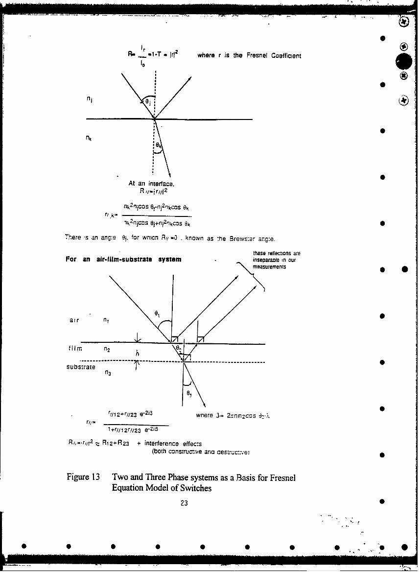
Figure 1 Test Configurations for switches 6Figure 2 Main Menu for Device Automation 7Figure 3 National InstrumentsIBCONF.COM Controller Settings 11Figure 4 National InstrumentsIBCONF.COM for a PC II 11Figure 5 ASYST Hardware Configuration Menu 12 0 @Figure 6 ASYST Overlay Selection Menu 13Figure 7 ASYST Memory Configuration 14Figure 8 Example of a Menu Definition 16Figure 9 Menu Status example for HP8116A.XXX 17Figure 10 Example of Lotus 1-2-3 interface commands 18Figure 11 Example of a DO LOOP from Appendix K- LBA 19 •Figure 12 Colon Definition from Program: JOE:XXX 22Figure 13 Two and Three Phase Systems as a Basis
for Fresnel Equation Model of Switches 26Figure 14 Power Dependence for Reflectivity of Planar Substrate Switches 27Figure 15 Two Step Use of Fresnel Equations to Calculate Film Index of
Refraction from Measured Reflectivity 28Figure 16 Gross Dependence of Reflectivity on Index of
Refraction of Films @488nm 29Figure 17 Dependence of Reflectivity on Index of Refraction of Films @514nm 30Figure 18 Power Dependence of Index of Refraction-Planar substrate 31Figure 19 Power Dependence of Reflectivity-Prism Substrate 32Figure 20 Laser Chemical Chemical Vapor Deposition Apparatus 36 0Figure 21 Transmission Electron Micrographs and
Electron Diffraction Pattern Obtained from Clusters 37Figure 22 Schematic Representation of Cluster Film Formation Process 38Figure 23 Fourier Transform Infrared Spectra of Aged and As-Deposited Films 39
3
000 0 0 00 0 0@

0
I troducfion-E ose O
Substantial progress was made in testing optical switches, in particular nonlinear interfaceswitches. Of equal importance was the goal of developing and optimizing methodology andapparatus for testing optical switches in general. We performed extensive testing of nonlinearinterface switches to determine whether the predictions of size enhancements of nonlinear opticlproperties of cluster films are true.
In order to accomplish testing of many types of switches, it is necessary to producepicosecond lacr pulses with highly correlated spatial, spectral and temporal properties. We neededto develop the capability of contacting light to the active regions of switches with greatprecision(±lOim). To attain sufficient precision, accuracy, speed and reproducibility, computercontrol is essential. Extensive work was done to configure apparatus so as to achieve a sufficientlyflexible mechanical mounting capability and a sufficiently flexible computer software"infrastructure" to facilitate testing of an arbitrary choice of switch.
In this effomt we chose to test nonlinear interface switches because these types of switcheshave already been showvn to have excellent characteristics for digital optical computing applicationsif they can be fabricated with materials having better nonlinear optical properties than earlier .1versions. Proof of principle research on earlier versions of nonlinear interface switches, along with
the general concepts outlined in the Final Report for Task P-9-6008, serves as an adequateintroduction to the theory and strategy of testing the tungsten oxide thin films. As a part of thiseffort, we developed a Fresnel coefficient formalism for evaluating the indices of refraction of thelaser deposited films which comprise the switches. This enables us to evaluate the photorefractiveproperties of the films as well as their static optical and electrical properties. These aspects of theeffort, which bear on the question of how these switches may be improve&,, will be covered belowafter a Pocedure section.
Prcdure
The materials fabrication1,2 and operational aspects of the switches3 will be described indetail in a separate section below. For our immediate intention of detailing the progress in setting
up general switch evaluatioi hardware and software, we note that switch evaluation wasaccomplished utilizing two basic approaches. In the first, the net reflectivity of a switch wasmeasured at a single laser power over a range of angles of incidence. This allowed determination ofthe angles of incidence over which a switch could potentially be evaluated in a NAND, OR or AND
4
LS* ,~ p
0 0 0 0 0 0 0 0 ". "O *

mode. Given the choice of angle of incidence, then the evaluation took the form of determining the
reflectivity as a function of laser power. If the index of refraction of any part of the switch is a
function of laser power, i.e. is photorefractive, then the reflectivity will be a function of laser
power. Detecting this effect is the essence of switch evaluation for this type of switch using pulse
trains. It should be emphasized that we employed this approach only as a polude to use of single
pulses in a pump-probe configuration.
A very brief description of the switching mechanism is in order at this point. The basic idea
is that whenever light encounters a boundary while traversing a region filled with two media
having differer t indices of refraction, part of the light is reflected and the other part is transmitted.
The proportion of the incident light which is reflected from the interface is proportional to the
difference between the two indices.This is in perfect analogy with what happens when an
electronic signal encounters an impedance mismatch while traveling between discrcte electronic
devices. Figures la and lb suggest this situation. If the film material is sufficiently photorefractive,
then it's index of refraction is a strong function of the optical power incident on it. The proportion
of the incident light reflected is thus a function of the amount of light which is incident upon it. As
will be discussed in greater detail later, this is the basis of all switching action for this kind of
device.
For a planar substrate, one can measure switching behavior by monitoring either the optical
power transmitted across the boundary or the amount of light which is reflected. Any deviation of
either of these optical powers from linearity, when plotted as a function of the incident power, is a
function of the degree to which either the film or substrate's index of refraction is a function of the
incident power. The use of the prism sub 'rate was suggested by the proof of principle research
and can be simply explained as follows. Whenever light encounters an interface between one
medium which has a greater index of refraction and another medium which has a lesser index of 0refraction, there will be a critical angle (see Figure lb angle C) for which all the light traversing the
interface will not be able to reenter the interface. The dependence of the reflectivity of the interface
near the critical angle is a very steep function of angle and so reduces the amount of photorafractive
behavior needed to observe switching. In addition, the incident and reflected light, with respect to
the prism-film interface, are separated from each other automatically. We will return to a discussion
of switching and device fabrication in a later section.
A software program called ASYST, which we describe software so as to serve as a primer
for future users, has been used to control and record data from various laboratory equipment with a
single personal computer.
5
• •
• • •• • • • ...

Film(On RHS for reflectivity, on LHS for TIR)
low From Laser •
To Detector for n. '
transmissivity To Detector
(on 26 stage)for reflectivity
"Spatial Filter
Klinger i (blocks back surfaceMicropositioners reflection) 0
(xvz)
Figure la(above). test configuration for films on planar substratesFigure lb(below). test configuration for films on prisms
* @2
A=Angle of incidence prism-airinterfaceB=Angle of refraction for incidentlight
C=critical angle fcr total internalrefraction(TIR)D=prism angle
C B E=right angle=D+B
E
6
0;
* 0 0* 0 00 0

ASYST SOFTVARE FOR LABORATORY DEVICES
Words in bold and italic print are commands or variables that needspecial attention, while words in bold, italic, and underlined are DOS file 0names. A large portion of this publication discusses topics covered in themanuals of ASYST. a software package currently being used at the Air ForcePhotonics Center. To better understand the software program, you may wantto refer to the manual- while reading this publication. Braces, [], areused to cite the manual and ?age number. The letter I represents theModule I Tutorial (Svstem. Graphics. Statistics) and the letter N 0
represents the additional manual &SYLT .I!0" Your Guide to ASYST's NewFeature Enhancements.
In order for a lab device to talk to a personal computer the devicemust have an interface, usually -ither a RS232 or IEEE-488 interconnect. 0Because RS232 can be rat! :r difficult to use we have used the IEEE-488interconnect whenever po:" ible. The IEEE-488 port is connected to apersonal computer through an interlink called GPIB (General PurposeInterface Bus). BASIC and C programming languages can control the GPIBsystem, but the programs would be long and tedious. The ASYST programminglanguage off- rs GPIB and RS232 control with graphics display, Lotus 1-2-3 0compatibility, and data plotting. ASYST has more commands than higher levellanguag.•. such as BASIC with the abil" .-y to create user defined commandwords to execure many ASYST commands- with one user defined word. ASYST canbe eas,"- to u.:, b-!t like a.1 programming languages it takes time tolearn.
GPIB Dh'UI' . MAIN M.ENU
DATE: 03-13/92
K.LINIGER STiiPPIHG MOTORS MEINU CONIFIGURATIONS
LASER BEAM ANALYZER EXIT TO THE 'OK' PROMPT
LASER POWER COIiTROLLER EXIT TO DOS 0
HO1-LINEAR OPTICAL SUITCH TEST
USAF PHOTOItlCS CENTER 0GRIFFIS AIR FORCE BASE
F'.fE, NEU YORK
by Brian De,'a, !
Figure 2. Main menu for device autormaion
7
S S 0 S S S S S •. @ 0O

0
DATA ACOUISITION FOR OPTICAL -ITCHES:I
OPTICAL SWITCH TEST SETUP 0
Using a mode-locked argon ion laser, the beam is first polarized andsent through a Laser Power Controller (LPC). A beam-splitter then splitsthe laser beam into two separate beams of unequal intensity. Mirrorsredirect the two beams to become nearly parallel and close together before 0entering a light shielded box. Upon enter the box the beams reflect andrefract from the surface of the film and the substrate. The reflected beamsare measured by a photodetector connected to a power meter. See Appendix -
A for a diagram of the laboratory.
ENVIRONMENTAL CONSIDERATIONS
Stray light from the laser beam reflected off various objects in thelaboratory caused unwanted intensities to be recorded. Emissions fromcomputer monitors and light from the outside hallway also affected ourreadings. To keep this unwanted light from reaching the detector a lIghtshielding box was constructed. A longer focal length lens replaced theprevious lens to allow the lens and mirrors to be outside of the box. Ablack cylinder, placed where the two parallel beams enter the box, helpblock stray light from entering the box. As we increased the beamintensity there were only three light sources left to eliminate. One sourcewas a reflection from one of the two beams at the focusing lens. Thisreflection angled above the substrate and reflected off the micrometers • *holding the substrate. Black tape was then used to cover the micrometersand minimize this reflection. The other sources were made when the beamscontacted the surface of the substrate and the beams were split intoreflected and refracted beams. The refracted beams continued through thesubstrate until contacting the other side of the substrate. At the otherside of the substrate the two refracted beams were split into reflected andrefracted beams. The reflected beams travelled back through the substrateand toward the detector. These second reflections were at a small distancefrom the first reflections and were blocked by a black spatial filter whichhad one hole to allow the first reflections through to the detector to emeasured. The third source was the light from the beams refracted throughthe substrate. This soura. reflected off the black wall of the box. This 0source was the most intense of the three sources of unwanted photons. Tominimize its reflectance, a block of black razor blades was put at the siteof reflection. Sporadic movement and vibrations of any of the devices,mirrors, and the argon laser are countered by a floating optics table.
8
* 0 S S 5 0 5 • ". "O 0
0
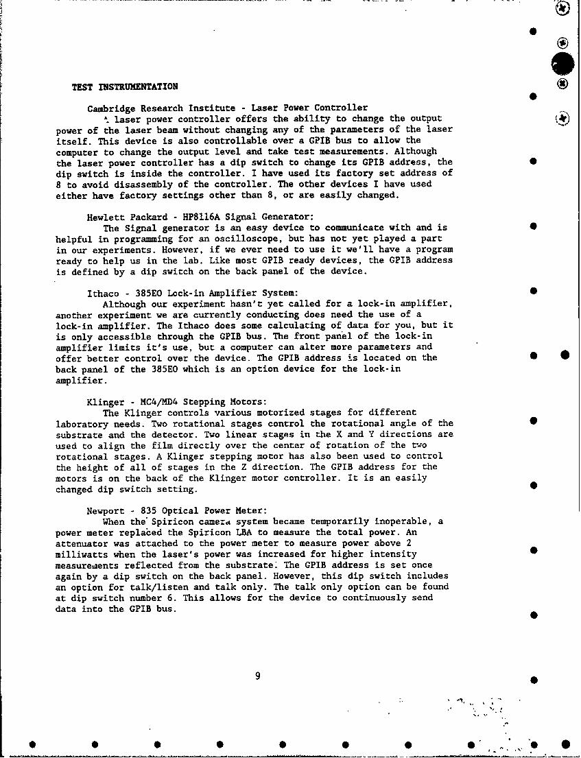
TEST INSTRUMENTATION
Cambridge Research Institute - Laser Power ControllerSlaser power controller offers the ability to change the output
power of the laser beam without changing any of the parameters of the laseritself. This device is also controllable over a GPIB bus to allow thecomputer to change the output level and take test measurements. Althoughthe laser power controller has a dip switch to change its GPIB address, the Sdip switch is inside the controller. I have used its factory set address of8 to avoid disassembly of the controller. The other devices I have usedeither have factory settings other than 8, or are easily changed.
Hewlett Packard - HP8116A Signal Generator:The Signal generator is an easy device to communicate with and is 0
helpful in programming for an oscilloscope, but has not yet played a partin our experiments. However, if we ever need to use it we'll have a programready to help us in the lab. Like most GPIB ready devices, the GPIB addressis defined by a dip switch on the back panel of the device.
Ithaco - 385EO Lock-in Amplifier System:Although our experiment hasn't yet called for a lock-in amplifier,
another experiment we are currently conducting does need the use of alock-in amplifier. The Ithaco does some calculating of data for you, but itis only accessible through the GPIB bus. The front panel of the lock-inamplifier limits it's use, but a computer can alter more parameters andoffer better control over the device. The GPIB address is located on the • 0back panel of the 385EO which is an option device for the lock-inamplifier.
Klinger - MC4/MD4 Stepping Motors:The Klinger controls various motorized stages for different
laboratory needs. Two rotational stages control the rotational angle of the 0substrate and the detector. Two linear stages in the X and Y directions areused to align the film directly over the center of rotation of the tworotational stages. A Klinger stepping motor has also been used to controlthe height of all of stages in the Z direction. The GPIB address for themotors is on the back of the Klinger motor controller. It is an easilychanged dip switch setting.
Newport - 835 Optical Power Meter:When the" Spiricon camerd system became temporarily inoperable, a
power meter replaced the Spiricon LBA to measure the total power. Anattenuator was attached to the power meter to measure power above 2milliwatts when the laser's power was increased for higher intensity •measuretaents reflected from the substrate: The GPIB address is set onceagain by a dip switch on the back panel. However, this dip switch includesan option for talk/listen and talk only. The talk only option can be foundat dip switch number 6. This allows for the device to continuously senddata into the GPIB bus.
9 0
• *0
0
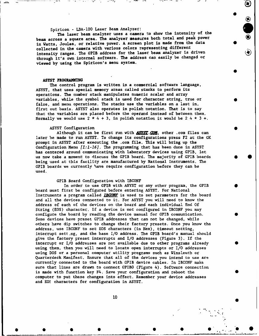
Spiricon - LBA-100 Laser Beam Analyzer:The laser beam analyzer uses a camera to show the intensity of the
beam across a square area. The analyzer measures both total and peak power
in Watts, Joules, or relative power. A screen plot is made from the data 0
collected in the camera with various colors representing differentintensity ranges. The GPIB address for the laser beam analyzer is driven ()through it's own internal software. The address can easily be changed or
viewed by using the Spiricon's menu system.
ASYST PROGRAINGThe control program is written in a commercial software language,
ASYST, that uses special memory areas called stacks to perform itsoperations. The number stack manipulates numeric scalar and arrayvariables, while the symbol stack is used for character string, true orfalse, and menu operations. The stacks use the variables on a last in,first out basis. ASYST also operates in polish notation. That is to saythat the variables are placed before the operand instead of between them.Normally we would use 2 * 4 + 3, in polish notation it would be 2 4 * 3 +.
ASYST ConfigurationAlthough it can be first run withA, other .com files can
later be made to run ASYST. To change its configurations press F2 at the OKprompt in ASYST after executing the .com file. This will bring up theConfiguration Menu [1:1-16]. The programming that has been done in ASYSThas centered around communicating with laboratory devices using GPIB, letus now take a moment to discuss the GPIB board. The majority of GPIB boards 0 0being used at this facility are manufactured by National Instruments. TheGPIB boards we currently have require configuration before they can beused.
GPIB Board Configuration with IBCONFIn order to use GPIB with ASYST or any other program, the GPIB 4
board must first be configured before entering ASYST. For NationalInstruments a program called IBCNF is used to set parameters for the boardand all the devices connected to it. For ASYST you will need to know theaddress of each of the devices on the board and each individual End OfString (EOS) character. If a device is not configured in IBCONF you mayconfigure the board by reading the device manual for GPIB communication. 0Some devices have preset GPIB addresses that can not be changed, whileothers have dip switches to change their factory presets. Once you know theaddress, use IBCONF to set EOS characters (in Hex), timeout setting,interrupt sett.ng, and the base I/O address. The GPIB board's manual shouldgive the factory preset interrupts and I/O addresses (Figure 3). If theinterrupt or I/O addresses are not available due to other programs already •using them, then you will need to locate open interrupts or I/O addressesusing DOS or a personal computer utility programs such as Winsleuth orQuarterdeck Manifest. Ensure that all of the devices you intend to use arecurrently connected to the board with GPIB device cables. In IBCONF makesure that lines are drawn to connect GPIBO (Figure 4). Software connectionis made with function key F4. Save your configuration and reboot the 0computer to put these changes into effect. Remember your device addressesand EOE characters for configuration in ASYST.
10 0
00 0 0 0 0 *0. 0

National Instruments Boar Characteristics ON PC-AT •
Board: G;PIB SELECT Cuse right'left arrow heg):
5ý1 a to 38secondary GPIN Address ........ • 01E
Timeout setting .. ,.... T3slOS byte ....$................. 1914Terninate Read on DOS ..... ... a esSet ZOI uith DOS on Write ..... yesTygpe of compare on EOS ........ 7-bitSet OI wo-last byte of Write .. yesGP 1I3-PC rmde I ................. P2Board is Sytem Controller .... • yesLocal Lockout on all deuices y. •jesDisable Auto Serial palling ... eDisable Device Unaddressing ... noHigh-speed tining ............. noInterrupt Jumper setting ...... 7Base I1.O Address ....... so..@ .... 82E1HDI•A channel .....I.................. 1Internal Clock Freq (in 11-H2) .. 6
Fl: Help F2: Explain Field F6: Beset Value Fg: Return to Map
Figure 3. National Instruments IBCONF.COM Controller Settings
National Instruments Deuice ap for Board GPIB IBe PC-AT o
SUse cursor control kegs to select a deuice or board.* Use function keys below to select desired action.J Use PgUp#PgDn to display naps for other boards.
- LECROY l DEUS DEU9 j . C4B •IDE2 DEUS6 I L DEA-188
I DEU3 I DEU7 DEU11 I1TH385
H 1UP11835 LPC n tC4A GEMl
FI: Help F4: Rename FS: (Dis)connect FO: Edit F9: Exit
Figure 4. National Instruments IBCONF.COM, GPIB - PC II 0
001I 0 •
0 5 ' "

ASYST Hardware Specifications:At the ASYST configuration menu first select hardware
configuration (Figure 5). ASYST is originally se: up for a slow computer 0with monochrome monitor and IBM printer. Chang.! tae selections in theHardware Configuration first so that you may make use of the selectionswhen continuing the configuration process [1:1-181. For instance, youcannot edit the color of the ASYST prompts unless your software isconfigured for a color monitor. 0
CPU Type CPU Type is 88286 or 88836CPU Speed CPU Speed is 16.88 Mf
•IBM Color Graphics Card, Black/W•ite MonitorPrinter IBM Graphics Printer
(for 288 vertical pixel display mode)
Active Kes
<Enter>: Select menu item or accept parameter for prompt<UpArrow>: Move to previous menu item or prompt(DownArrow>: Hove to next menu item or prompt(leftArroo>: Hove to menu item or prompt to the left<RightArrow>: Hove to menu item or prompt to the right<Home>: Move to the first menu item or prompt * *<End>: Move to the last-menu item or prompt<Esc>: Exit current menu or prompt list
0
Figure 5. ASYST Hardware Configuration Menu
Selecting ASYST Overlays:ASYST has many sets of command words for different functions.
Select only the overlays of command words for the functions that you willneed (Figure 6). These overlays take up plenty of memory, so don't loadoverlays you will not use! If you are going to use the GPIB system you mustload GPIB master and the overlay for your particular GPIB board [1:1-16]. •Each of the driver overlays contains commands for more than one GPIB board.Choose only the driver overlay that contains your computer's GPIB board.For a list of supported GPIB boards and the driver overlays refer to Module4 GPIB/IEEE-488 Appendix D of the ASYST manuals. The Help Overlay doesn'toffer much help for the memory it takes up and I suggest not loading this
12
* 0 * 0 0 00 ,0 *

j
GPIB Device ConfigurationEach GPIB device to be utilized by ASYST must be assigned. The •
program needs to know the EOS characters, I/O addresses, their user definednames, and whether the EOS characters arb on or off. Next you'll need toinitialize the GPIB bus. Initializing the bus takes three ASYST commandswhich I have shortened to one called init (see Appendix C - ShortCommands). Since the GPIB board I was recently working with allows only 16devices I created a text file called QP1B3.U to assign all of the devices 0with their EOS character, address, and name (Appendix D - GPIB DeviceConfigurations). This text file is automatically loaded by my main textfile program and allows the GPIB Device Configuration file to be editedfrom an option given in the main menu.
Making Menus 0In the latest version of ASYST, menu command words were added to
create user defined menus for other users unfamiliar with the program[N:3-1]. Menus are subprograms of special command words. These exclusivemenu commands are used only inside a menu definition. The menu is first
HP8116A.MENU 0MENU.STATUS HP8116A.STATUSMENU.BLOW.UP1 1 24.79 MENU.SHAPEC5B C5F MENU.COLORC5P MENU.PROMPT. COWOR1 1 " CHANGE PARAMETERS" MENU.ITEM( SGCP.MEIN ) 03 1 " EXECUTE DESIGNED PROGRAMS" MENU.ITEM( SGDP.MENU J5 1 " ENABLE / DISABLE FRONT PANEL" MENU.ITEM( LOCK.OUT.SWITCH )
MENU.END
Figure 8. Example of a Menu Definition
declared using the command menu followed by the name of the menu to bedefined. The menu definition begins with the name of the menu. The menudefinition terminates when the menu reaches the menu command Menu.End(Figure 8). A menu is basically a text window with executable items for theuser to choose from. The size and location of the menu is determined by thecommand Menu..hape . Any predefined colon definitions, overlay commands,basic ASYST commands or other menus are executable in the menu by using thecommand word Menu. Item. This command also defines the location and text tobe displayed as a menu option. Excluding the menu title and menu selectionsall other text can be displayed by a user defined colon definition executedby the menu command called Menu.Status. For GPIB device menus this commandcan be used to display current data from the device such as signalgenerator parameters in the program HP8U6A.x= (Figure 9).
13
0 S 0 0 S 0 0
O • •• • • • "O

0
HP8116A. STATU7S 12 FOREGROUNDDISPLAY.DATA 13 FOREGROUND26 8 GOTO.XY . CURRENT PARAMETER SETTINGS"0 8 GOTO.XY 2' "58 8 GOTO.XY ' ............ .. ... ...... "1 10 GOTO.XY ." Amplitude:" 40 10 GOTO.XY " Output Disabled:"1 11 GOTO.XY ." Offset:" 40 11 GOTO.XY " Autovernier:"1 12 GOTO.XY ." Operating Mode:" 40 12 GOTO.XY " High Level"1 13 GOTO.XY ." Control Mode:" 40 13 GOTO.XY " Low Level:"1 14 GOTO.XY .' Trigger Slope:" 40 14 GOTO.ZY ' Burst Number:"1 15 GOTO.XY 2' Haversine(-90):" 40 15 GOTO.XY " Repetition Rate:"1 16 GOTO.XY ." Waveform:" 40 16 GOTO.XY " Sweep Start Freq:"1 17 GOTO.XY 2' Frequency:" 40 17 GOTO.XY " Sweep Stop Freq:"1 18 GOTO.XY ." Duty Cycle:" 40 18 GOTO.ZY ' Sweep Marker Freq:"1 19 GOTO.XY ." Width:" 40 19 GOTO.XY " Sweep Time:"1 20 GOTO.XY 2' Limit (on/off):" 40 20 GOTO.XY " Complement (on/off):"II FOREGROUND ;
Figure 9. Menu.Status example from HP8116A.XXX
As a special note the menu commands look decent in normal display, butappear slightly worse in graphics display mode.
Arrays and TokensASYST arrays are very similar to arrays in any other programming
languages [1:5-1]. They can have multiple dimensions and can be accessed 0one element at a time. These arrays can also be accessed one dimension at atime or you can change the entire array all at once by using the array namethe same as you would a scalar variable name [1:18-1]. To access onedimension at a time you can u'e the I character as a wildcard viriable withthe ASYST command 1SEC" directly in front of the accessing braces( ex. ZSE=T [ 2 . I . 5 1 ). This creates a cross sectional view of thearray. If a portion of a dimension is what you desire use the command Subin front of the braces. However, you cannot use the I character in a Subcommand. ASYST also offers string arrays that are limited to two dimensionswith one of the dimensions being the maximum character length of a string.Because ASYST does not automatically make use of expanded memory, tokensbecome an important tool for users to make use of a 286, 386, or 486 withexpanded memory. Tokens are defined by taking the data and size of analready existing array. In che ASYST memory configuration, memory isallocated for unnamed arrays as well as a token heap. If you are usingexpanded memory the token heap size will not make a difference in yourprogramming, but the size of the unnamed array heap can limit the maximumsize of your arrays and your tokens. It would be more beneficial for userswith expanded memory to increase the unnamed array memory allocation bydecreasing the named array memory. This will allow for larger sized tokensin expanded memory. Keep in mind that when you enter a saved program fromDOS all arrays are blank and your tokens have no size, data or place inexpanded memory. You will then have reload tokens into expanded memory,
14 0
. ]
S SS 05
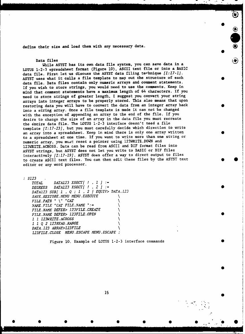
0define their size and load them with any necessary data.
Data filesWhile ASYST has its own data file system, you can save data in a
LOTUS 1-2-3 spreadsheet format (Figure 10), ASCII text file or into a BASICdata file. First let us discuss the ASYST data filing technique [1:17-1].ASYST uses what it calls a file template to map out the structure of eachdata file. Data files contain only numeric arrays and comment statements.If you wish to store strings, you would need to use the comments. Keep inmind that comment statements have a maximum length of 64 characters. If youneed to store strings of greater length, I suggest you convert your stringarrays into integer arrays to be properly stored. This also means that uponrestoring data you will have to convert the data from an integer array backinto a string array. Once a file template is made it can not be changedwith the exception of appending an array to the end of the file. If youdesire to change the size of an array in the data file you must recreatethe entire data file. The LOTUS 1-2-3 interface doesn't need a filetemplate [1:17-23], but you must carefully decide which direction to writean array into a spreadsheet. Keep in mind there is only one array writtento a spreadsheet at one time. If you want to write more than one string ornumeric array, you must reset a pointer using 123WRITE.DOWN and123WRITE.ACROSS. Data can be read from ASCII and DIF format files intoASYST strings, but ASYST does not let you write to BASIC or DIF filesinteractively [1:17-19]. ASYST does offer a way to direct output to filesto create ASCII text files. You can then edit these files by the ASYST texteditor or any word processor.
:S123TOTAL DATA123 XSECT[ ! , 1 ] :-DEGREES DATA123 XSECT[ ! , 2 ] :=DATA123 SUB[ 1 , Q ; I , 2 1 EQUIV> DATA.123SAVE. RESTORE. MENU MENU. EXECUTEFILE.PATH " \ "CATNAME.FILE "CAT FILE.NAME ":-
FILE.NAME DEFER> 123FILE.CREATEFILE.NAME DEFER> 123FILE.OPEN \1 1 123WRITE.ACROSS1 1 Q 2 123READ.RANGEDATA.123 ARRAY>123FILE123FILE.CLOSE MENU.ESCAPE MENU.ESCAPE ;
Figure 10. Example of LOTUS 1-2-3 interface commands 0
150
00 0 0 0 0 0 0 0
0
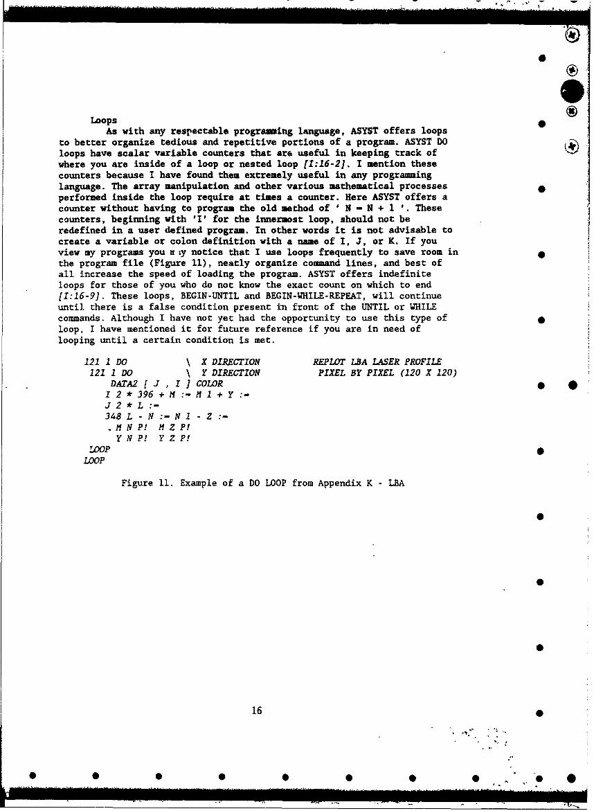
Loops •As with any respectable programming language, ASYST offers loops
to better organize tedious and repetitive portions of a program. ASYST DOloops have scalar variable counters that are useful in keeping track ofwhere you are inside of a loop or nested loop [1:16-2]. I mention thesecounters because I have found them extremely useful in any programminglanguage. The array manipulation and other various mathematical processesperformed inside the loop require at times a counter. Here ASYST offers acounter without having to program the old method of ' N - N + 1 '. Thesecounters, beginning with 'I' for the innermost loop, should not beredefined in a user defined program. In other words it is not advisable tocreate a variable or colon definition with a name of I, J, or K. If youview my programs you f Ly notice that I use loops frequently to save room inthe program file (Figure 11), neatly organize command lines, and best ofall increase the speed of loading the program. ASYST offers indefiniteloops for those of you who do not know the exact count on which to end[1:16-9]. These loops, BEGIN-UNTIL and BEGIN-WHILE-REPEAT, will continueuntil there is a false condition present in front of the UNTIL or WHILEcommands. Although I have not yet had the opportunity to use this type of •loop, I have mentioned it for future reference if you are in need oflooping until a certain condition is met.
121 1 DO \ X DIRECTION REPLOT LBA LASER PROFILE121 1 DO \ Y DIRECTION PIXEL BY PIXEL (120 X 120)
DATA2 [ J, IJ COLOR * *I 2 * 396 + :- M I + YJ 2 *L:-348 L - N :- N I - Z.M N P! Z P!
Y N P! Y Z P!"LOOP
LOOP
Figure 11. Example of a DO LOOP from Appendix K - LBA
16
0 0 0 00 0 0

0
SPECIFIC DEVICE AUTOMATION •
Cambridge Research Institute - Laser Power Controller -
CRI offers their laser power controller with different optionsbuilt into it. It a helpful note is to make sure which type you are usingin order to correctly program for the specific parameters it has. We areusing a model that can change the percent power or keep thetransmissibility at a specified amount. Our experiment calls for thecontrol of the output power. Control of the device can be difficult attimes with an erratic laser beam. If you try to specify a power level wherethe percent amount of transmission can peak at times over 100%, than thecontroller will be in error and leave the power level at its present state.Ensure that when you wish to communicate with the controller that a laserbeam is present. If the laser beam isn't going through the controller yourcommunication will cause a system crash and you will need to restart theASYST program by using Control-Break.
Hewlett Packard - HP8116A Signal GeneratorAlthough communicating with the signal generator can be simple,
the number of different parameters adds length to my program. The basic usefor the program is to save particular parameter settings to be restored atlater dates quickly and easily,
Ithaco - Lock-in AmplifierThe most difficult part of programming for the lock-in amplifier •
was figuring out the data format, Ithaco sends a numeric code thatdescribes the output data, The data may come in 64 different combinationsof 7 formats. Displaying which formats are currently being used iscumbersome to say the least. I had to make sure that if all formats werebeing used the length of display wasn't longer than the length of availablescreen space, This makes displaying the data itself rather arduous, I hadto limit the amount of data to 10 different sets at a time.
Klinger - Stepping MotorsThe Klinger stepping motors are an essential part of our
experimental setup. My ASYST programming allows easier control over thestepping motors. My program displays the counters of the four axes of onecontroller, and offers moving a motor to a specified count. I have madechanging the stepping rate or speed of the motor more accessible thanthrough the front panel of the controller. In my program I was faced withthe problem of inputting a letter designating a particular controller andchanging it to an integer such as A-l, B-2, C-3, etc. Inside my colondefinition for CHOOSE.XOWrMDLLER the user inputs a letter and 'UPPERinsures that the letter is capitalized. I then change the ASCII letter toit's numeric counterpart. Since the upper case ASCII characters start at65, I then subtract 64 from the decimal character. Now an 'A' will be seenas 1 and a 'B' as 2 and so on. The useful note to make here is that forsome reason unknown to me, ASYST would not correctly recognize the letterdirectly following an input statement. This causes a slight problem, but I
17 0
0 S 00 0 0 0 0',
0
was able to work out a simple solution. After the input statement theletter is saved into a variable, ED. I tried to take the ASCII value of thevariable KD, but I would always be returned with the ASCII value of K. Inorder to get around this irritating snag I put the ASCII command and myvariable ED into a string. I then used WECW to execute the commands insidethe string, and it worked.
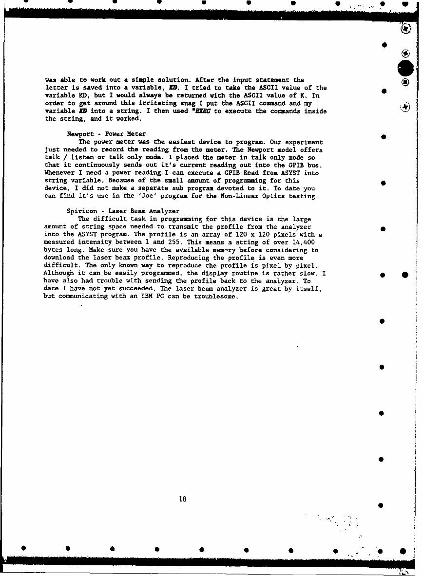
Newport - Power MeterThe power meter was the easiest device to program. Our experiment
just needed to record the reading from the meter. The Newport model offerstalk / listen or talk only mode. I placed the meter in talk only mode sothat it continuously sends out it's current reading out into the GPIB bus.Whenever I need a power reading I can execute a GPIB Read from ASYST intostring variable. Because of the small amount of programming for thisdevice, I did not make a separate sub program devoted to it. To date youcan find it's use in the 'Joe' program for the Non-Linear Optics testing.
Spiricon - Laser Beam AnalyzerThe difficult task in programming for this device is the large
amount of string space needed to transmit the profile from the analyzerinto the ASYST program. The profile is an array of 120 x 120 pixels with ameasured intensity between 1 and 255. This means a string of over 14,400bytes long. Make sure you have the available memnry before considering todownload the laser beam profile. Reproducing the profile is even moredifficult. The only known way to reproduce the profile is pixel by pixel.Although it can be easily programmed, the display routine is rather slow. 1 *have also had trouble with sending the profile back to the analyzer. Todate I have not yet succeeded. The laser beam analyzer is great by itself,but communicating with an IBM PC can be troublesome.
0
0
18
0 0
* 0 00 0 00 0
r. • *
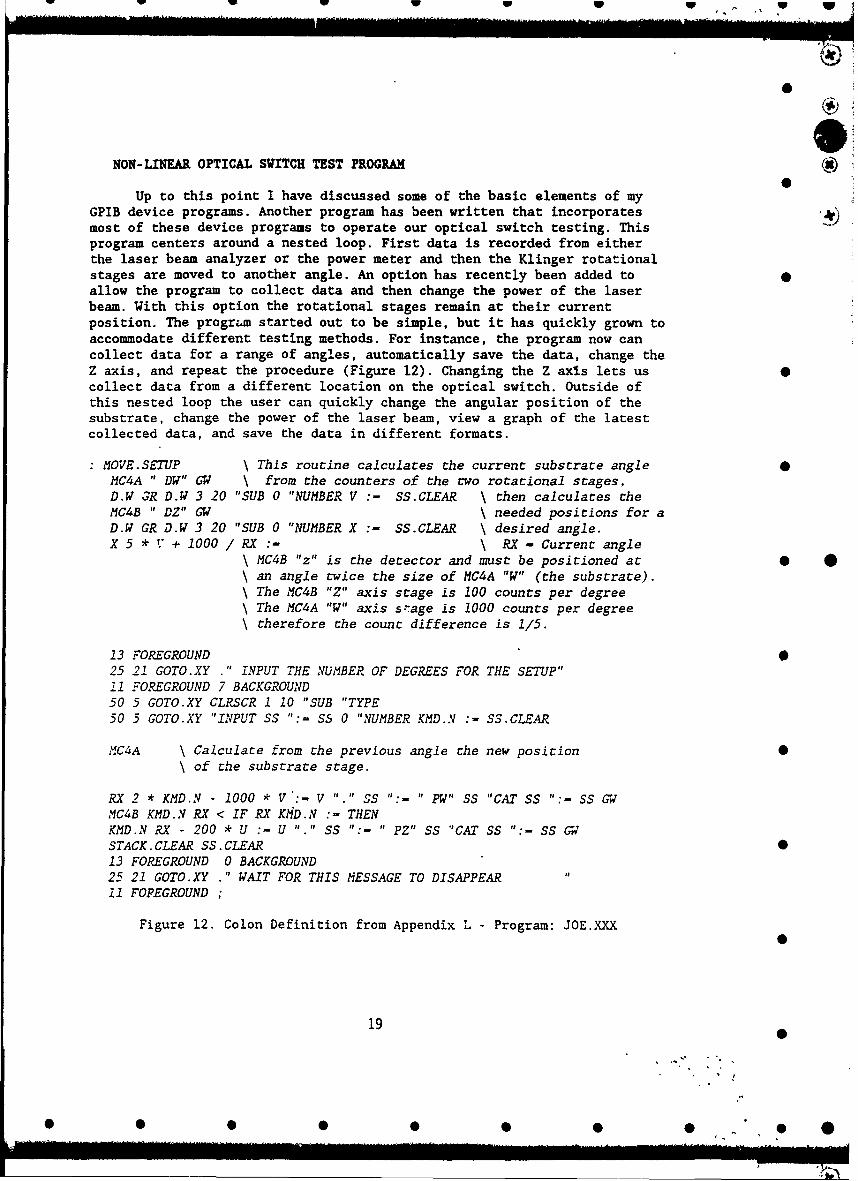
NON-LINEAR OPTICAL SWITCH TEST PROGRAMUp to this point I have discussed some of the basic elements of my
GPIB device programs. Another program has been written that incorporatesmost of these device programs to operate our optical switch testing. Thisprogram centers around a nested loop. First data is recorded from eitherthe laser beam analyzer or the power meter and then the Klinger rotationalstages are moved to another angle. An option has recently been added toallow the program to collect data and then change the power of the laserbeam. With this option the rotational stages remain at their currentposition. The program started out to be simple, but it has quickly grown toaccommodate different testing methods. For instance, the program now cancollect data for a range of angles, automatically save the data, change theZ axis, and repeat the procedure (Figure 12). Changing the Z axis lets us 0collect data from a different location on the optical switch. Outside ofthis nested loop the user can quickly change the angular position of thesubstrate, change the power of the laser beam, view a graph of the latestcollected data, and save the data in different formats.
MOVE.SETUP \ This routine calculates the current substrate angle 0MC4A " DW" GW \ from the counters of the two rotational stages,D.W 3R D.W 3 20 "SUB 0 "NUMBER V :- SS.CLEAR \ then calculates theMC4B " DZ" GW \ needed positions for aD.W GR D.W 3 20 "SUB 0 "NUMBER X :- SS.CLEAR \ desired angle.X 5 * V + 1000/ RX :- \ RX - Current angle
\ MC4B "z" is the detector and must be positioned at 0\ an angle twice the size of MC4A "W" (the subscrate).\ The MC4B "Z" axis stage is 100 counts per degree\ The MC4A "W" axis s!'age is 1000 counts per degree\ therefore the count difference is 1/5.
13 FOREGROUND25 21 GOTO.XY ." INPUT THE NUMBER OF DEGREES FOR THE SETUP"11 FOREGROUND 7 BACKGROUND50 5 GOTO.XY CLRSCR 1 10 "SUB "TYPE50 5 GOTO.XY "INPUT SS ":= SS 0 "NUMBER KMD.N :- SS.CLEAR
MC4A \ Calculace from the previous angle the new position 0\ of the substrate stage.
RX 2 * KMD.N - 1000 * V :- V "." SS ":- " PW" SS "CAT SS ":- SS GWMC4B KMD.N RX < IF RX K9D.N :- THENKMD.N RX - 200 * U :- U "." SS ":- " PZ" SS "CAT SS ":- SS GWSTACK. CLEAR SS. CLEAR 013 FOREGROUND 0 BACKGROUND25 21 GOTO.XY ." WAIT FOR THIS MESSAGE TO DISAPPEAR11 FOPEGROUND
Figure 12. Colon Definition from Appendix L - Program: JOE.XXX
19 0
0 0 0 00 0 0
Changing the angle of the substrate requires some calculation. Therotational stage holding the detector is located beneath the stages holdingthe substrate. This means that for every degree that the detector moves,the substrate also moves that same amount. Because we need to measure thereflected beam, the detector must be at an angle twice the angle of thesubstrate. For a desired substrate angle e, the detector must move to aposition of 2e. The substrate then must move an angle e in the negativedirection. To accomplish this feat, the current angle is first calculatedfrom the current axis positions. For our setup the "W" axis on the firstcontroller operates the substrate rotational stage. The second controlleroperates the detector rotational stage on the "Z" axis. To add to thecomplexity, the rotational stage for the substrate (MC4A "W") moves at arate of 1000 steps per degree. The detector stage (MC4B "Z") moves at therate of 100 steps per degree.
After the current angle RX is calculated, the desired angle is theninputted by the user as HD .N. The desired position of the stage iscalculated from the difference between the previous angle and the desiredangle with an adjustment based upon the type of stage.
The rest of the colon definitions are similar to definitions found inthe device specific programs. Because I had taken the time to developprograms for each individual device, I can now easily program forcombinations of different devices with some of the necessary colondefinitions already defined.
AUTOMATED DEVICE CONFIGURATION
As I increase the number of devices on the GPIB bus and in myprogram, I notice the amount of available program memory quickly decreases.ASYST constricts your conventional memory and tokens can only offer alittle help. I have designed a way to easily change which devices areloaded into memory. The program is configured with only the device menusthat are needed. The program is then re-saved on to the hard drive with a •different name for fast loading from DOS. This keeps devices that are notbeing used from taking away your precious memory. Whenever my main menuprogram is initially loaded a menu configuration option is offered. Throughthis menu you can select the separate menus that you want, or don't wantloaded. You can also change the GPIB device characteristics such as name,end of string character code, and GPIB device number. Mouse support is also •configured. All of these settings can than be saved under a new name to beopened from DOS. The entire program -3 reloaded, but the menu configurationoption will have been deleted. When you finally leave the current program,you can enter the saved ASYST program with the name that it was savedunder. You'll notice that it won't bave to take time to load the program,because it was already loaded when it was saved. The menu options will be •only those that you had selected earlier. This process makes my programmingmore versatile to the demands of the laboratory. Although it is easy to useand may not appear to do much, it is extremely complex and hard to program.
20
20/
* 0 6 0 0 0 0 0, 0. @,
I.I
ADVANTAGES TO ASYST
My use of ASYST has centered on its GPIB control. The GPIB bus allowscontrol of diffe.-ent devices from one computer. This makes laboratorycontrol easier. The GPIB bus is manipulated effectively in ASYST. The newmenu commands make my programs more user friendly. Designing similar menus 0in higher level languages wo".,d take many hours to program. The menus allowfor other people to easily operate our experiment without hours oftechnical program training. One adventage that I favor is the colondefinitions. These definitions are similar to macros, but are easier tocreate and modify with an ASCII text editor. ASYST also offers statisticalanalysis, mathematical computations, and graphical analysis that takes timeto program in any higher level language.
DISADVANTAGES OF ASYST
ASYST (version 3.1) doesn't make use of expanded memory available inIBM 386 and 486 PCs except in tokens. Tokens help a little, but plenty ofconventional memory could be saved for calculations and data manipulationif the entire program was loaded into expanded memory. If more conventionalmemory was freed the processi Pg time would increase and so would themaximum size of any arrays. I have recently conversed with personnel fromthe ASYST who assured me that a new version will be coming out soon makingbetter use of expanded memory. Instead of making a DOS window, ASYST makes * *its own interface. This limits the amount of DOS commands available insideASYST and some of the commands are used differently. It is usually easierto exit to DOS rather than use the DOS interface commands. Although I waspleased with the ASYST menu commands in the normal display mode, the menudisplay in graphics mode did not work as well. I'm hopeful that in the nextversion their problems •will be solved.
FUTURE USE OF ASYST IN OPTICAL SWITCH EVALUATION
Our evaluation setup will be measuring the transmitted and reflectedlight from the switch with an EG&G Optical Multi-channel Analyzer (OMA) •and an Inrad Autocorrelator. The OMA system will analyze the spectrum ofthe light to include the wavelength. A GPIB connection will be made fromthe keypad of the EG&G spectrograph. The computer will then control thescanning of the grating inside the spectrograph., which is receiving thetransmitted or reflected laser beam. The autocorrelator will then beconnected to a LeCroy 9450 Oscilloscope. The oscilloscope will be able to 0save waveforms, find deviations, full width at half maximum with thebackground light subtracted, and separate between the two peaks of thesplit laser beam. The computer will then be connected through GPIB to theOscilloscope for da-a .•xcraction and furt• r analysis.
21
0
* 0 0 0 0 S 0 0 " 0 • '

Specific Considerations Regarding Testing of Nonlinear Interface Optical Switches
There are inherent limits in how precisely we can determine the reflectivity versus angle ofincidence function. Fi-st, the angle of incidence cannot be fixed more precisely than the angular )divergence of the laser beam at the point of incidence. In turn, the angular divergence is a functionof the focussing used to bring the laser to the switch surface. The greater the desired peak power tobe delivered to the switch, the shorter the focal length lens needed and the more imprecisely known
the angular divergence. The position of the laser is fixed and the switch must be rotated, asillustrated in Figurela, through a given angle without moving the irradiated surface in any linear
direction with respect to the laser focus.
The detectors must move synchronously with respect to the switch because to determine thereflectivity, both the incident power and the reflected power must be measured at each angle. Themotion of the switch must be controlled to within several tens of microns to insure, that only onepart of the switch surface is probed during the entire evaluation, that the same part of the laser focalvolume contacts the switch during the course of the evaluation and that the size of the laser
contacted region does not fluctuate beyond that dictated by geometry during the evaluation. Usingthe notation from the three phase system modelled by Figure 13, this latter requirement involvesthe fact that as the angle of incidence becomes larger, the region irradiated by the laser smoothly * *chinges from a circle at *1--90' to almost a line near 15=00. The angular precision is changing
throughout as well because the contacted region changes shape continuously. The laser power andpolarization must be precisely determined and controlled so that it does not fluctuai.ý during thecourse of an evaluation. As the degree of focussing of the laser becomes tighter, the tolerances onthese parameters only become more less precise. Considering that the intrinsic divergence of ourlaser pulses is in the range of milliradians to tens of milliradians, and that relatively long focallength lenses, 25cm, were used to focus the light onto the switches, the angular measurements in
the results are thought to be precise to ±102 mrad.
Results
Operational and Testing Considerations
The notation used is suggested by the drawings of the experimental arrangement given inFigure 13. The top diagram is for a standard two phase system and the lower drawing is relevant tothe three phase system which resembles our switches. Two procedures were used to obtain the
22
• Q •• • • •' •
R- _ 1-T jrr2 where r is the Fresnel Coefficient
nii
At an interface. ,R //-.; r//12
nk2,jjCOS e.-ni2nIkCOS Ok
Ilk2np-•S @i+nj2-kCOS Ok
There'-s an anc_:e 9i, for wnicn R// .0 known as :he Brews:=-r arc:e.
these reflections areFor an air-flim-substrate system inseparaole in our :
""uirmon,
f ilm n
rI112+rl123 e"2i3 wniere 3 - 2.:.nn.c-c s •.
1+rl/12r!1/23 e-2iB
R/,=,ri/12z R,2•AR23 + interference effec. s
(both construc:;ve anci ces-,ruc-::ve: •
Equation Model of Switches
23
ti k
1•2fljCOS G•+• • 1k"OS ek

030
40.
4-6
4d~
VI
949, *
, - '.
.4.' 4O-I, -
A -E
14424

Si
Figure 15. Iteration of Fresnel Equations to Obtain a Range of Reflectance Values. o
x = 1.. so x is the range variable. MathCad allows a range of 50 for each variable used.
this is the initial value for the index of refraction of the thin film withn = 2.55 an index value that gives us the reflectances we observed from F8I2RMP2.XLS
at 40 degrees incident angle.
n2(,+ n2 X + .ooi this is the incremental step for the index values.
nl = I Index of Refraction of first medium (air).
n3 = 1.489392 Index of Refraction of third medium (substrate).
01 =68 Angle of Incidence on the first boundary measured from the normal.
Olp -01. X Conversion from degrees to radians. 0180
02X asin - .sin(0lp) )-8 Application of Snell's Law to achieve refracted angle from first boundary(2- n2x X
02px = 02x.-- Conversion from degrees to radians.
03x = asin(n-.sin(02p0 , -180 Iteration of Snell's Law once again provides us with\n3 • X the refracted angle from the second boundary. •
0 3px 0 3x" x Conversion from degrees to radians yields
(n2 2.cos(OlIP) - nl-n2 cos(02prl 2 x 2 1 X- X' x) Formula used to calculate the coefficient of reflectivity at the 12 boundary.rlx (n2X) 2. COS(0 1 p) + nlI -n2x. cos (02p.)•
(n23 2. CO Sia proes too oban0or2aPh 3 onayr23x (n~ ) 2.os( 3Px) + n2 .n3 eos 02p. \ x --.imiiar process to obtain e.o.r. at the 23 boundary.(n2x)2. COS(03P) + l2.~n3.o~s(02p)\
Xý X) *
h = .0000002 Thickness of thin film.
X .000000514 Wavelength of incident light.
2."xh.n2x'cos(O2Px)Bx =
rl2x + r23x.eXp(- 2i.Bx) Complex Coefficient of Reflectivity.rX + (rl2x.r23x.exp(-2i.BX)) I
Rx =(r \j2 ReflectanceSxi/2
25
S
* 0 S 0 0 0 0 0 ,0- ,S..... ............................. ....... .... ....... il[ ]1 . .... ... .. ....... .... ..... i ..... .. " ... .. ...... li I .. in11111h . ..

Fresnel equation Modelusing Mathcad
t P i HH ............................... ." ..; ................. •
... ....... 4 .. .......
II
Film Index from Fresnel's Equations by ASYST0520F01.WK1
0.07 T 0
0.06 ..wuu.um 3W n "
o0.04-00.03
0 0.020.01
0A2.18 2.19 2.2 2.21 2.22 2.23 5
Film Index
Figure 16. Gross Dependence of Reflectivity on Index of Film 0
26S
0 0 0 0 0 0 0 ,. 0

w 9 9 0 0 0 , w
Figure 17. Dependence on Reflectivity on Index at 514 nm
0.03500503 2.550.03512137 2.5510.03523829 2.5520.03535579 2.553 0.042
0.03547386 2.5540.0355925 2.5550.0357117 2.556
0.03583147 2.557 0.04
0.03595181 2.5580.03607269 2.5590.03619414 2.56 Rx oo00.03631613 2.5610.03643868 2.5620.03656176 2.563 _
_0.0366854 2.5640.03680957 2.5650.03693427 2.566).070591! 256"-'•0.0340.03705951 2.567 2.54 2.55 2.56 2.57 2.58 2.59 250.03718528 2.568 n20.03731157 2.5690.03743838 2.57- Plot of Reflectance vs. Index of Refraction at 514 nm0.03756571 2.5710.03769356 2.572
0.03782192 2.5730.03795079 2.574 S 00.03808016 2.575
0.03821003 2.576
0.0383404 2.5770.03847127 2.578
0.03860262 2.579
0.03873446 2.580.03886678 2.581
0.03899958 2.5820.03913286 2.5830.0392666 2.5840.03940081 2.585 00.03953549 2.5860.03967062 2.587
0.03980621 2.5880.03994225 2.589
0.04007874 2.59
00.04021567 2.5910.04035304 2.5920.04049084 2.5930.04062907 2.5940.04076773 2.5950.04090681 2.596 90.04104631 2.5970.04118623 2.5980.04132655 2.599 27
0 0000 0 0 0

WO Filmr Dota from F812RAMP XLS 30 Incident angle
2.23
2.225
2.22
-• 2.215
02.21
2.205
22 I
0 50 100 150 200 250
LPC Powr (mWJ
0
Figure 18. Power Dependence of Index/Planar Substrate
0
0
0
28
• •• •• •• * , I .
0 S 5 5 0 "0",0

First Prism Film 680 Incident Angle
0.0880.087 •
0.085 6
p0.084 - *
S0.0830.082 -0.081 -0.08
0.0790.078 L- I I I I
0 0.2 0.4 0.6 0.8 1 1.2 0Incident Power (mW)
First Prism Film 68° Incident Angle * 0
0.084 T0.082 nuin ass a* an,,==0.08 -- se,,en•
C 0.078 a ass
0.076 1s
0.0740.072
0.072
0 5 10 15 20 25 0Incident Power (mW)
0Figure 19. Power Dependence of Reflectivity/Prism Substrate
29
0
0 0 0 0 0 0 0 ., ,*

index of refraction. Our fir-. approach involved use of the crossing angle ,6 1, between reflectance
vs angle curves for th- hl.1aik substrate and the film-substrate system. Figure 14 shows such a setof curves. The index L f refm,'cton of the film can be shown to a function of the crossing angle, i.e.=600C for the data sh av.,Tý. The fact that the reflectance curves for the film system are apparentlynot identical at two different laser powers strongly suggests that the films are photorefractive. Thefact that the reflectivity curves of the same blank substrate are indistinguishable at the two differentlaser powers shows both the reproducibility of the measurements and the poor photorefractivity ofcommercial quartz.
Since we require the index of refraction of the films as a function of laser power, and thereare geometric ambiguities concerning interpreting the interaction as a function of angle, we insteaddevised a method to determine the index of refraction of the films for a given angle. This method isdescribed using Figure 15 and is a direct application of the Fresnel equations(see Figure 13). Theindex of refraction of the films effectively deteLmines the angle of incidence of the light with.respect to the film substrate interface so the equations are solved repetitively for a range of valuesof the film index n2. Useful tables and graphs such as are shown in Figures 16 and 17 can beconstructed using these equations which relate measured reflectivities to values of the film index ofrefraction. Given the known values for the index of refraction of the substrate, the film thicknessmeasured using profilimetry, the wavelength of the light and the other nonadjustable parameters * *given in Figure 15, Figures 16 and 17 give the index of refraction of the film at either 488 nm or514 nm based on the measurement of the net reflectivity without any adjustable parameters. Alsoshown is representative data obtained from the switches. Figure 18 shows data relating themeasured index of refraction of a switch as a function of incident power. Considering thereproducibility of our reflectance measurements, each of the data points in Figure 18 could havevertical error bars on the order of 0.005. The totality of our results suggest that index changes on
the order of 10-2 for application of 1-102 mW onto spot sizes having 101-102 diameters areprobable.
The other type of procedure involved putting the film on the hypotenuse of a right triangleprism. This allowed use of angles very close to that required for total internal reflection within thefilm volume. Such an arrangement was first employed by Tomlinson et al in their proof of pprinciple research. Figure 19 shows two such graphs in which the net reflectivity is plotted as afunction of the laser power for a fixed angle of incidence. The curves are clearly nonlinear in a waywhich is different from a blank substrate.We have not yet converted these reflectance
measurements into index of refraction measurements but it is clear that a Fresnel equation approach
along the lines described above would be applicable.
30
0
• • •• • • •" •.

S~0
To motivate a discussion of our results on the testing of nonlinear interface optical
switches, it is necessary to present some background on materials and device fabrication.
Materials and Device Fabrication
A variety of theoretical studies support the expectation that metal clusters4 , metal oxide
clusters5 , dielectric coated metal clusters 6 , and even dielectric coated voids7 in thin metal films will
have an enhanced electrical polarizability compared to materials with the same chemical
composition but without the the submicroscopic physical features. Thin films of such materials
should have enhanced photorefractive properties leading to applications 8 in nonlinear optics,
optical computing and related technologies. We have recently shown9 ,10 ,1 1 how to deposit thinfilms composed of platinum clusters using laser chemical vapor deposition(LCVD). Such films
have the unusual optical/electrical property of being "transparent metal" electrodes suggesting
various applications. LCVD cluster synthesis utilizing non-noble metals is fundamentally differentfrom that of other metals so we now present recent results demonstrating the synthesis of non-
noble metal and metal oxide clusters and thin films composed of such clusters. In the particular * *case we describe below, we use gas phase metal carbonyl precursors. As it turns out, we alsodemonstrate the unanticipated result that carbonyl impurities are localized on the surfaces,regardless of whether metal or metal oxide clusters are synthesized.
0Although the present results relate to tungsten and tungsten oxide cluster films, the
chemistry is directly applicable to other oxidizable metals. Puretsky and Demyanenko 1 2 report that
gas phase clusters and ultrafine particles can be synthesized using excimer laser dissociation of all
group six metal hexacarbonyls. Our earlier work on platinum clusters and our current results on
other metals both suggest that the clusters which are present in our films are formed by gas phaseprocesses. In fact, manyl3, 14 ,15 have studied UV dissociation, in both single and multiphoton
limits, of metal hexacarbonyls in the context of depositing thin films for microelectronic devicefabrication. Incorporation of partially decarbonylated species and reaction products derived fromthese species are a disadvantage of LCVD of metallization patterns for microelectronic applications.
We have recently shown that use of noncarbonylated precursors in laser chemical organometallic
synthesis of platinum clusters also results in incorporation of organic impurities but that they can
be removed and potentially utilized via post-deposition chemistry. Gas phase and post-deposition
31
• -,q0
0 0 S 00 0 0
chemistry is limited by the tendency of the metal to oxidize which makes the results we nowpresent quite distinct from our earlier LCVD platinum results.
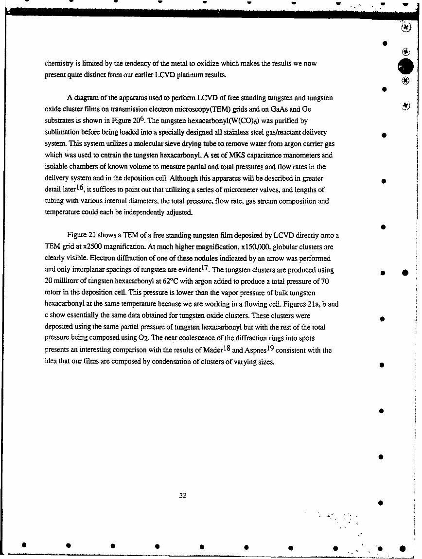
A diagram of the apparatus used to perform LCVD of free standing tungsten and tungstenoxide cluster films on transmission electron microscopy(TEM) grids and on GaAs and Gesubstrates is shown in Figure 206. The tungsten hexacarbonyl(W(CO)6) was purified by
sublimation before being loaded into a specially designed all stainless steel gas/reactant deliverysystem. This system utilizes a molecular sieve drying tube to remove water from argon carrier gaswhich was used to entrain the tungsten hexacarbonyl. A set of MKS capacitance manometers and
isolable chambers of known volume to measure partial and total pressures and flow rates in thedelivery system and in the deposition cell. Although this apparatus will be described in greaterdetail later1 6, it suffices to point out that utilizing a series of micrometer valves, and lengths oftubing with various internal diameters, the total pressure, flow rate, gas stream composition andtemperature could each be independently adjusted.
Figure 21 shows a TEM of a free standing tungsten film deposited by LCVD directly onto aTEM grid at x2500 magnification. At much higher magnification, x150,000, globular clusters areclearly visible. Electron diffraction of one of these nodules indicated by an arrow was performedand only interplanar spacings of tungsten are evident1 7 . The tungsten clusters are produced using * *20 millitorr of tingsten hexacarbonyl at 62rC with argon added to produce a total pressure of 70mtorr in the deposition cell. This pressure is lower than the vapor pressure of bulk tungstenhexacarbonyl at the same temperature because we are working in a flowing cell. Figures 21a, b andc show essentially the same data obtained for tungsten oxide clusters. These clusters weredeposited using the same partial pressure of tungsten hexacarbonyl but with the rest of the totalpressure being composed using 02. The near coalescence of the diffraction rings into spots
presents an interesting comparison with the results of Mader 1 8 and Aspnes 19 consistent with theidea that our films are composed by condensation of clusters of varying sizes.
0
0
32
0
* S 0 00 0 0
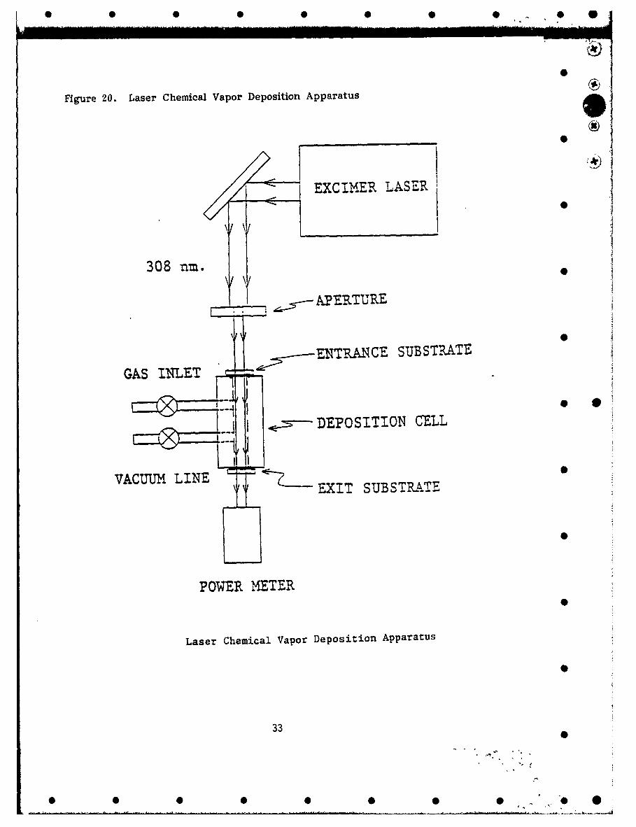
Figure 20. Laser Chemical Vapor Deposition Apparatus
EXCIMvER LASER
308 nm.
APERTURE
GAS -L-TENTRANCE SUBSTRATEGAS INLET -]'
I ~~-DEPOSITION CELL
VACUUMCU LINE • •• TVU LEEXIT SUBSTRATE
POWER MIETER
Laser Chemical Vapor Deposition Apparatus
33 0
* * 0 0 0 0 0 0 •' O 0

S.. . .. . . .. . . .... il]
0
particular overlay. Editor overlay is a simple ASCII text editor foraltering user defined ASYST text programs. Although it is not needed, it is 0more convenient than leaving ASYST, loading another ASCII editor or wordprocessor, and then returning to ASYST. If you plan on using the menu 4-command words for driving your programs than you should load the overlayMenu Tools. Other suggested overlays to load are Data Files, and the Lotus1-2-3 File Interface found in File Overlays. This section is also importantin minimizing the memory that these overlays use. After selecting the 0overlays you desire and press Escape, the program will ask if you want topermanently store them. Answer yes, otherwise the overlays you selectedwill not be loaded. Be sure of your choices or you .may have to start allover.
Editor EditorHelp System Data filesArray Editor Lotus 123 File InterfaceRS-232 GPIB Mtaster jAlgebraic Parser Type 2 NEC GPIB driverMlenu Tools Mlenu ToolsFile Overlays PCX File SupportGraphics Overlays PixelAnalysis OverlaysData Acquisition • *GP lBGIB-
Base Dictionary: 5816Synbol Table: 4181Ouerlay Memory: 5615 Type: 0 - for overlay descript-ionString Segment: 6074 W - to find a desired uordArray Menory: 48548 <esc> - exit menu
Figure 6. ASYST Overlay Selection Menu
GPIB Board Configuration.:After entering the board's bus number, which is usually zero,
you can select which GPIB board your PC has from the highlighted list ofchoices. If your GPIB board is listed but not highlighted you must returnto the Overlay Configuration and choose the correct driver overlay. Referto ASYST Module 4 GPIB/IEEE-488 Appendix D for a list of supported boardsand their driver overlays. The program will then ask several questions for
34 0
0 0 0 00 0 0
configuration depending on which type of GPIB hoard your computer uses. Youwill want to have ready the base address, interrupts, and controller 0address.
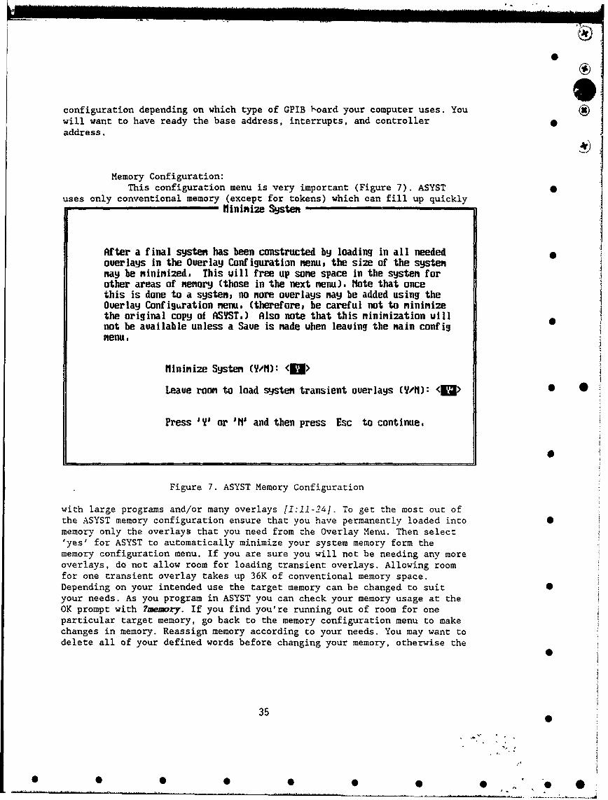
Memory Configuration:This configuration menu is very important (Figure 7). ASYST 9
uses only conventional memory (except for tokens) which can fill up quicklyflininize Systen
After a final systen has been constructed by loading in all neededoverlays in the Overlay Configuration menu, the size of the systennay be nininized, This will free up sone space in the systen forother areas of menory (those in the next menu), Note that oncethis is done to a systens no uore overlays nay be added using theOverlay Configuration nenu. (therefore, be careful not to ninini2ethe original copy of ASYST.) Also note that this minimization willnot be available unless a Save is made when leaving the nain config •menu.
finini2e Systen (yWM): <U>
Leave rooa to load systen transient overlays (U/M): <a> • 0
Press I'Y or 'I1 and then press Esc to continue.
Figure 7. ASYST Memory Configuration
with large programs and/or many overlays [1:11-24]. To get the most out ofthe ASYST memory configuration ensure that you have permanently loaded intomemory only the overlays that you need from the Overlay Menu. Then select'yes' for ASYST to automatically minimize your system memory form thememory configuration menu. If you are sure you will not be needing any moreoverlays, do not allow room for loading transient overlays. Allowing roomfor one transient overlay takes up 36K of conventional memory space.Depending on your intended use the target memory can be changed to suit 0your needs. As you program in ASYST you can check your memory usage at theOK prompt with ?memory. If you find you're running out of room for oneparticular target memory, go back to the memory configuration menu to makechanges in memory. Reassign memory according to your needs. You may want todelete all of your defined words before changing your memory, otherwise the
35
35 0
0 0 0 00 0 0
W®
memory configuration will be permanently saved with your currently definedword definitions. You may need to increase your conventional memory fromDOS. This can be done by no installing devices such as fastopen, serveand =puse on in your Corx iz..sy and Autoexec.bat files into memory. If youhave a 386 you can use the DOS expanded memory manager, or a similarmanager such as the Quarterdeck OEM-386, to load these and other devicesinto high memory.
Saving ASYST ConfigurationsYou can save your configurations when you try to exit the
configuration menu or type save filename.ext at the OK prompt. Bothprocedures create a .ovl and a .com file to execute from the DOS prompt.You can save your configurations with your defined words or text programsloaded into memory. This saves time in loading them every time you enterASYST from the DOS prompt. GPIB users keep in mind that if you were alreadyinitializcd and "talking" to GPIB devices when you made the save, you stillmust re-initialize the GPIB bus when you run your saved program. A specialnote, all arrays and tokens are emptied during this save. Arrays keep theirsize, but not their data. Tokens lose size, data and place in memory if youhad them put into expanded memory. 0
36
0
* 0 5 5 0 0 5 0 "0 0

Figure 21. (a) TEM photo of high pressure tungsten film and (b) corresponding 6)
electron diffraction pattern. (c) TEM photo of high oxygen pressure film and,d) corresponding electron diffraction pattern.
Ox
0
* 0
0
37 0
S0 0 0 0 0 0 0 0 O0
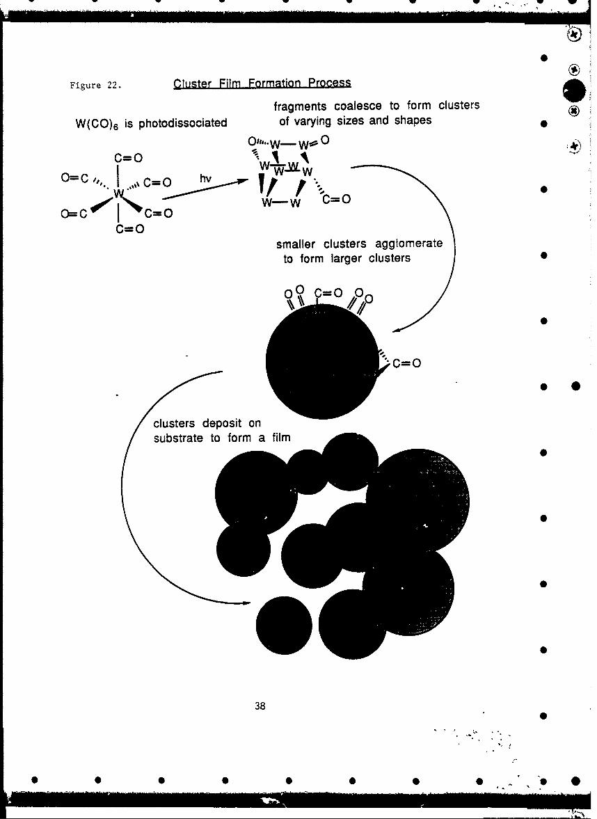
Figure 22. Cluster Film Formation Process
fragments coalesce to form clusters
W(CO) 6 is photodissociated of varying sizes and shapes
O"'"W- WO 0c=o • 1 "
C=O
smaller clusters agglomerateto form larger clusters 0W~ 0- =0/a
o0
clusters deposit on
substrate to form a film
0.0
0
0 0 •
38
0
• • • •• •• •'"O

Figure 23. FT-IR Spectra of Aged and Nascent Film
020
* I I
IIlls
-Uwie.f.$AS (cm-"!
(54w
.wo 4i• lea0
W14 8
-- 39I'll
39
• • • •• O• ,. e

Figure 22a shows an Fourier Transform Infrared Absorption Spectrum(FT-IR spectrum) of
a nascent tungsten film deposited as described above onto a Ge substrate. There is evidence of a
surface oxide2 0 which probably forms immediately upon exposure of the film to the atmosphere.
The carbonyl stretches are clearly visible and occur at 1935, 1942, and 1962 cm-I. All of these
frequencies are coo high to be characteristic of bridging carbonyls suggesting that the carbonyl does
not exist in an environment conducive to bridging between metal atoms. This almost rules out anenvironment internal to the clusters. An FT-IR of the same film aged in air for nearly a year clearlywhich can be seen in Figure 22b shows that the carbonyls have reacted with airborne oxygenfurther suggesting that they could not have been buried deep in the cluster. The carbonyl stretchingfundamentals are still clearly visible and are not characteristic of bridging interactions 2 1 . Figure22c
shows a nascent film which was deposited under identical conditions for LCVD production of themetal oxide clusters. The carbonyl stretches(1969, 2008, 2106 cm- 1) are again clearly visible and
not characteristic of bridging. In both Figure 22b and 22c, the sharp FT-IR features just below
3000 cm- 1 are as yet not unambiguously assignable. We currently believe they can be identifiedwith formate formed by the catalytic coupling of water and CO which we believe could occur onthe cluster surfaces. Although we are currently performing a variety of experiments to support thisassertion, if our surmisal is correct, the water could be supplied from the substrate or theatmosphere. * *
The TEM results demonstrate the existence of clusters. The FT-IR results show thatbridging carbonyls are never present in either nascent or films extensively aged in air. Reactions ofthe carbonyls associated with the films are indicative of surface bound carbonyl. We are currently
pursuing other chemical means of utilizing the carbonyl impurities as reactant for producingcomposite films from the nascent LCVD films we have shown here.
Heating the tungsten oxide films in vacuum and ;n an oxygen environment has potentiallyuseful consequences. Raman spectroscopy shows that such films heated in oxygen begin to show
features at = 800cm- 1 indicative that the tungsten-oxygen begin to organize themselves into
octahedra. This is significant because such octahedra are thought to be necessary for thephotorefractive effects observed in titanates and niobates. Heating the films in vacuum produces
peculiar blue films which ESCA shows contain tungsten in the +4 oxidation state. This issignificant because such electron rich species might be able to provide highly polarizable chargecarriers. These charge carriers would enhance the photorefractive properties of the films. ESCA of
nascent laser deposited tungsten oxide films clearly show the presence of small amounts oftungsten +5 which is necessary to produce tungsten bronzes. Other metal ions, involving e.g. Ti+2
40
0
0 0 00 0 00 0 . 0 0

-. .... . . .. . -lll I '- . . . . . . . . . . . • .. I w I . . . .
and Nb+2 , analogous to these unusual W species, are required to achieve the photorefractive
properties of the well known titanate and niobate photorefractive materials.
Correlation of film composition with static and dynamic index of refraction measurements
is best accomplished using ESCA, UV-visible and infrared spectroscopic methods in both
absorption and reflection. Current plans involve use of Kramers-Kronig relations to obtain
complete index measurements across the entire IR-UV spectrum. Film composition is not well 0
determined by Auger spectroscopy because of electron beam induced changes in the film and
because of the small spot size in which measurements are made. Using Auger, the spot size is
commensurate with the size of the clusters and so many measurements must be made to obtain
accurate average values for the film metal-oxygen stoichiometry. 0
Discussion
We have demonstrated that we have provided films composed of metal oxide clusters. We 0
have measured two types of optical data both of which suggest the films have measurable nonlinear
susceptibilities. Attempts to quantitate the amount of refractive index change are imprecise but, for
films =200A thick, could be as high as 10-1 Wattn4 at 514 nm. Obtaining precise estimates is
possible but reproducibility makes it a challenge. Use of a prism hypotenuse as a switch substrate 0 0seems to give an output which is much more sensitive to the film's photorefractive response. These
results will be discussed in the context of the switch evaluation and the design criteria and
properties of the nonlinear interface approach to switches in general.
0Given the multitude of predictions which have been made considering the optical and
electrical properties of clusters, we felt it important to definitively establish their presence in theswitches we were able to fabricate. We varied fabrication conditions such that the cluster size
distribution varied from an average of about a few 101A in diameter to multi-10 2A diameters.Basedon existing calculations, clusters in the size range /1l0 to 1.52% should possess enhanced nonlinear
optical properties. The data suggests: 1) we have developed the capability to observe
photorefractive effects with great sensitivity, and 2) it may well be true that we have already
observed some very large effects. We are cautiously encouraged by these results but we know that 0
more work is required to make unequivocal statements.
One problem is the difficulty in establishing the reproducibility of the results. Further, the
results we currently have are not yet good enough to suggest a physical mechanism underlying thephotorefractive properties, i.e. a X3 or X2 effect. Since we have established that the quartz
41
0 S 0 0 0 0 0 0 '.0 0

substrates have extremely small nonlinear optical coefficients, any change in the reflectivity can betaken to be mostly caused by the film's properties. Since the refractive index can be readily relatedto the induced polarization, which in turn can be related to the applied optical intensity via the usualexpansion in the nonlinear susceptibility, given better data we know we will be able to determinethe type of interaction leading to the photorefractive effects.The data in the figure is typical of whatwe have obtained repeatedly. Recall that we showed in Figure 17 that we can collect extremelyreproducible data. This has led us to suggest that the films are somehow being irreversibly changedby the. evaluation process. The chemistry we have observed using FT-IR clearly shows that there issome irreversible chemistry which occurs over very long periods of time. Perhaps the testingregimen accelerates this process. We employed the analytical methods mentioned in the Resultssection to discover the possible modifications which could be taking place.
However, so far all methods we used to analyze the films were static methods. It is quitepossible that the photorefractive effects we are observing occur on the timescale of the laser pulses,i.e. 100 psec. Such effects would not be unambiguously observable using the static methods so faremployed. Note that the fastest photorefractive effects, would be based on nonresonant interactionsand that these would certainly only be observable on the timescale of the laser pulses or faster. Thefastest photorefractive responses are those involving the smallest amount of movement of mass.Purely electronic motions are therefore obviously the fastest. The only way to definitively explore * •these possibilities is to use single pulse pump-probe experiments which are planned for the nearfuture. Based on UV-visible spectroscopy, we plan experiments at longer wavelength, 800-900nm, which should be more nearly resonant with an absorption and therefore even morestrongly photorefractive. What we lose in speed might be compensated for in the strength of the
response.
Perhaps the most interesting result of this study is the sense that the nonlinear opticalproperties of the clusters are very impressive. Since the switches we have tested are composed offilms we have shown to be nominally =200nm thick, and the clusters average 102A in diameter, itis clear that the films are only 10-20 clusters thick. For a spot size of 501.im in diameter, aconservative estimate, only 104-105 clusters are being used to produce a single element switch.This suggests that the theoretical shot noise limit on the signal to noise ratio for a single shot test ofthe switch should be =100. Lack of uniformity of the films, in either thickness and/or composition,will only degrade this expectation. Since the spot size changes shape and size as the angle ofincidence is varied, uniformity can clearly become an issue. However, for a test in which the angleof incidence in kept constant while ramping the incident power, the growth in focal volume, due todiffraction, imposes must less stringent constraints. Thus, the total internal reflection
42
Sm0
0 0 0 0 0 0 0 0, 0

configuration, Figure Ib, should definitely be the choice for future nonlinear interface optical
switch work.0
Simulations strongly suggest that use of substrates like ZnS will be advantageous in allswitching application because they more closely match the static index of the film(s). The effectswe observe are almost certainly purely electronic in nature and involve no movement of masswhatsoever. Attempts to make cluster films which are thicker have not been successful so far. This 0is because we have needed to modify our deposition apparatus. Currently, as the films get thicker,
they begin to undergo ablation about as much as thickening by additional deposition. This problem
can be overcome by using LCVD without contacting the films. Thicker films will allow more
clusters to be involved in the switching process and should therefore increase the photorefractiveresponse.
Conclusions
The films used for implementing nonlinear interface switches may indeed display largephotorefractive effects. The evaluatio, %f such switches must be carried out using single pulse,pump-probe methods to eliminate the; .s.siility of artifacts. A total internal reflectionconfiguration is strongly indicated for implementing switch devices in future effort. It is clear the 0 0best embodiment of a nonlinear interface switch is with a prism as a substrate. Use of planar "substrates has allowed definite determination of the static index of refraction of the films. Use ofprism substrates allows use of an angle of incidence which is so close to the critical angle for totalinternal -eflection at the film-air interface that the only leakage through the film is due to the angular 0
divergence of the laser beam.
References
1 M. J. Casey, J. Chaiken, M. Villarica, J. Phys. Chem. 1992 0
2 M. J. Casey, J. Chaiken, J. M. Osman, Nonlinear OpticsJlII Proc. SPIE (1992), 1626,
217-2253 P. W. Smith, W. J. Tomlinson, P. J. Maloney, J. P. Hermann, IEEE J. Quant. Elec.
(1981)QE-17, 340-347 04 Das, P., Metiu, H. J. Phys. Chem. 89, 4680-4687(1985)
43 0
0 0 0 00 0 0 .0
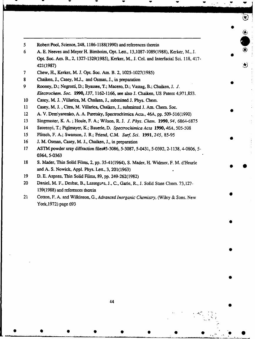
5 Robert Pool, Science, 248, 1186-1188(1990) and references therein
6 A. E. Neeves and Meyer H. Bimboim, Opt. Lett., 13,1087-1089(1988), Kerker, M., J.Opt. Soc. Am. B., 2, 1327-1329(1985), Kerker, M., J. Col. and Interfacial Sci. 118, 417-
421(1987)
7 Chew, H., Kerker, M. J. Opt. Soc. Am. B. 2, 1025-1027(1985)
8 Chaiken, J., Casey, M.J., and Osman, J., in preparation
9 Rooney, D.; Negrotti, D.; Byassee, T.; Macero, D.; Vastag, B.; Chaiken, J. J.Electrochem. Soc. 1990,137, 1162-1166, see also J. Chaiken, US Patent 4,971,853.
10 Casey, M. J. ,Villarica, M. Chaiken, J., submitted J. Phys. Chem.
11 Casey, M. J. , Citra, M. Villarica, Chaiken, J., submitted J. Am. Chem. Soc.12 A. V. Dem'yanenko, A. A. Puretsky, Spectrochimica Acta., 46A, pp. 509-516(1990)
13 Singmaster, K. A. ; Houle, F. A.; Wilson, R. J. J. Phys. Chem. 1990, 94, 6864-6875
14 Szorenyi, T.; Piglmayer, K.; Bauerle, D. Spectrochimica Acta 1990, 46A, 505-50815 Flitsch, F. A.; Swanson, J. R.; Friend, C.M. Surf. Sci. 1991,245, 85-95
16 J. M. Osman, Casey, M. J., Chaiken, J., in preparation17 ASTM powder xray diffraction files#5-3086, 5-3087, 5-0431, 5-0392, 2-1138, 4-0806, 5-
0364, 5-036318 S. Mader, Thin Solid Films, 2, pp. 35-41(1964), S. Mader, H. Widmer, F. M. d'Heurle
and A. S. Nowick, Appl. Phys. Lett., 3, 201(1963)
19 D. E. Aspnes, Thin Solid Films, 89, pp. 249-262(1982)
20 Daniel, M. F., Desbat, B., Lassegue's, J., C., Garie, R., J. Solid State Chem. 73,127-139(1988) and references therein
21 Cotton, F. A. and Wilkinson, G., Advanced Inorganic Chemistry, (Wiley & Sons. New
York, 1972) page 693
0
44
• • •• • • • "O0

0 =0
. .......
.........Deg....... ..
N..n-Liner Opicl.wic.Tstng..... ---- -
utocrreltur eamSplitte
.... ~~ ......
Bench
.... .... ....
450

II Appendix B -Program: GP11.XXX (Main Menu)*
GRAPHICS.DISPLAY VUPORT.CLEAR \CLEAR ALL ASYST STACKSNORHAL.DISPIAY FORGET.ALLSS.CLEAR STACK.CLEAR,ECHO.OFF
MENU FOR GPIB OPERATING DEVICES
by Brian K. DeVaul
\ Some commonly used commands have been shorten to save typing\ speed. There is a list of the newly defined words in the file\ called GPIB2.XXX.
AA~AAA4A~AAALOAD OPERATING SUBFILES FOR GPIB PROGRAM ****i**/
LOAD GPIB2.XXX \ SHORT COMMANDS FILE* *LOAD GPIB3.XXX \ GPIB CONFIGURATIONSLOAD GPIB4 .XXX \ COMMON VARIABLES
***********DEFINE OPIB MAIN MENU SPECIFIC VARIABLES ~**~***
INTEGER SCALAR NUMBER. OF. MODULESINTEGER SCALAR FIRST.LOADINTEGER DIM[ 50 ] ARRAY CMDAT36 STRING MODULE.MENUDIM4[ 21 ,36 1STRING.ARRAY MODULESDIM[ 21 ,36 1STRING.ARRAY MODULES.DESCO FIRST.LOAD .
O NUMBER.OF.MODULES :
46
1"1
• 000~®

**************** DEFINE OPERATING COLON DEFINITIONS ******** * /
MOUSE0 0 0 0 CALL.MOUSE 4 *DROP65535, SET.MOUSE.INT13 27 SET.MOUSE.BUTTONS3 0 0 0 CALL.MOUSE 4 ROLL DROP
LOAD.GPIB.MODULES
FILE. OPEN DATAFILE.XXX20 1 DO I COMMENT> MODULES "[ I ] ":- LOOP20 1 DO I 20 + COMMENT> MODULES.DESC "[ I ] ":- LOOP1 SUBFILE CMDAT FILE>ARRAY
FILE. CLOSE
21 1 DO \ COUNT THE NUMBER OF MODULES BEING LOADEDCMDAT [ I ] 1 - IF Z 1 + Z :- THEN
LOOP Z NUMBER.OF.MODULES :-
1 CMDAT [ 22 ] -IF 1 FIRST.LOAD :-0 CMDAT [ 22 ] :-THEN\ DETERMINES IF THE MENU CONFIGURATION WAS USED
11 1 DO CMDAT [ I ] 1 \ LOAD MODULES DESIGNATED IN CMDATIF " LOAD " MODULES "[ I ] -TRAILING "CAT \ LOAD name.XXX
".XXX" "CAT "EXEC SS.CLEAR \ • 0THEN
LOOP1 CMDAT [ 1i ] -IF MOUSE THEN ; \ IF DESIGNATED, LOAD
\ MOUSE SUPPORT
.-****************** LOAD DEVICE SPECIFIC SUBFILES * / 0
LOAD.GPIB.MODULES \ USE COLON DEFINITION FOR LOADINGLOAD GPIB5.XXX \ LOAD MENU CONFIGURATION MENU
47
.......................................... •o
4. S
0 0 0 0
- -• -•--~--~-- -' -• -" "O 0

0
AAAAA~AA*AAJAAAAA.AAA Designing the MAIN menu *********
PROMPT MENU.ESCAPE ;0
LOAD. MENU. ITEMS \SETUP MENU OPTIONS FOR THE LOADED3 X :- NUMBER.OF.MODULES Z :- \MENU PROGRAMS
20 1DO CMDAT II]O0IFELSE Z7 <
IF X 2 + X :-ELSE X 1 + X :-THEN
MENU.ITEM( -MODULES -[ I -CAT - .MENU " "CAT " ""CAT
MODULE.MENU ":-X 5 MODULES.DESC "[ I ] MODULE.MENU` "EXEC
THENLOOP
5 Z :-\OFFER MENU CONFIGURATIONS IF THERE0 FIRST.LOAD - \ WASN'T A PREVIOUS SAVEIF 5 45 " MENU CONFIGURATIONS" " MENU.ITEM( CONFIG.MENU -" EXECELSE THEN
MAIN.STAT \ITEMS TO BE DISPLALYED WITH MAIN MENU4 FIRST.LOAD -IF 2 FIRST.LOAD :- CONSOLE MENU.ESCAPE THEN12 FOREGROUND60 1 GOTO.XY ."DATE: "1 "DATE "TYPE \DISPLAY CURRENT DATE9 FOREGROUND40 16 GOTO.XY ."USAF PHOTONICS CENTER"* *40 17 GOTO.XY ."GRIFFIS AIR FORCE BASE"40 18 GOTO.XY ." ROME, NEW YORK"10 FOREGROUND60 2-1 GOTO.XY ."by Brian DeVaul"11 FOREGROUND
MAIN. MENU \DEFINED MENU NAME ( GP1B4.XXX)"1 GPIB DEVICE MAIN MENU" MENU. TITLE \MENU.STATUS MAIN.STAT \DISPLAY COLON DEFINITION1ENU. BLOW. UP1 1 24 78 MF.NU.SHAPE \SIZE OF THE MENU0 11 M ENU. COLOR \FOREGROUND AND BACKGROUND COLORS15 MENU. PROMPT. COLOR \HIGHLIGHT COLORLOAD. MENU. ITEMS \LOAD MENU OPTIONS7 45 " EXIT TO THE 'OKI PROMPT" MENU.ITEM( PROMPT9 45 " EXIT TO DOS" MENU.ITEM( BYE
MENU. END0
0
48
000 0 *0

\ \\START MENU PROGRAM
START11 1 DO CMDAT [ I]1 1 \RELOAD TOKENS AND ARRAYS THAT ERASED DURING
IF " RELOAD.- MODULES [ I CA -T"EXEC THEN _ SAVE.LOOPSCREEN. CLEARINIT INITIALIZE IPIB IMAIN.MENU\ MENU.EXECUTE BEGIN MENU PROGRAM
GO START
CONFIG RESTART [ SAVE NEWLY CONFIGURED PROGRAM AFTER RELOADING1 FIRST.LOAD 0
IF FILE.OPEN DATAFILE.XXX 41 COMMENT> FILE.NAME2 FIRST.LOAD :- 1 SUBFILE CMDAT ARRAY>FILE FILE.CLOSE" SAVE '~FILE. NAME "CAT "EXEC
INIT .\INITIALIZE GPIBELSETHEN;0
CONFIG.RESTART \IF THIS FIRST TIME LOADED, FIRST.LOAD I0
0
490
*0 0 0 0 0 0 0, 0
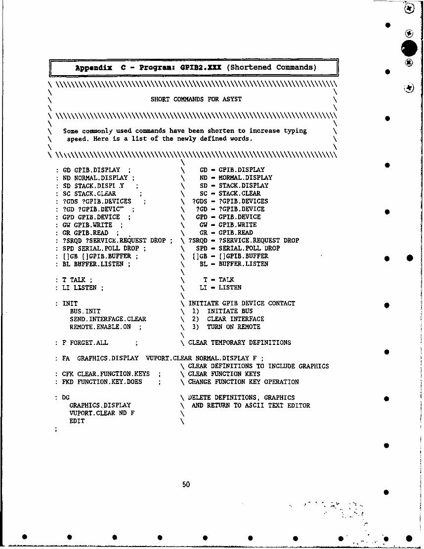
Appendix C - Program: GPID2.IXX (Shortened Commands) *
SHORT COMMANDS FOR ASYST
\ Some commonly used commands have been shorten to increase typing\ speed. Here is a list of the newly defined words.
: GD GPIB.DISPLAY ; \ GD - GPIB.DISPLAY: ND NORMAL.DISPLAY ; \ ND - MORMAL.DISPLAY: SD STACK.DISPI X ; \ SD - STACK.DISPLAY: SC STACK.CLEAR ; \ SC - STACK.CLEAR: ?GDS ?GPIB.DEVICES ; \ ?GDS - ?GPIB.DEVICES: ?GD ?GPIB.DEVIC" ; \ ?GD - ?GPIB.DEVICE: GPD GPIB.DEVICE ; \ GPD - GPIB.DEVICE: GW GPIB.WRITE ; \ GW - GPIB.WRITE: GR GPIB.READ ; \ GR - GPIB.READ: ?SRQD ?SERVICE.REQUEST DROP ; \ ?SRQD - ?SERVICE.REQUEST DROP: SPD SERIAL.POLL DROP ; \ SPD - SERIAL.POLL DROP: []GB []GPIB.BUFFER ; \ []GB - [IGPIB.BUFFER 1: BL BUFFER.LISTEN ; \ BL - BUFFER.LISTEN
\3
: T TALK; T- TAIK: LI LISTEN, \ LI- LISTEN
: INIT \ INITIATE GPIB DEVICE CONTACTBUS.INIT \ 1) INITIATE BUSSEND. INTERFACE. CLEAR \ 2) CLEAR INTERFACEREMOTE. ENABLE. ON ; \ 3) TURN ON REMOTE
F FORGET.ALL \ CLEAR TEMPORARY DEFINITIONS
: FA GRAPHICS.DISPLAY VUPORT.CLEAR NORMAL.DISPLAY F ;\ CLEAR DEFINITIONS TO INCLUDE GRAPHICS
: CFK CLEAR. FUNCTION.KEYS ; \ CLEAR FUNCTION KEYS: FKD FUNCTION.KEY.DOES ; \ CHANGE FUNCTION KEY OPERATION
:D \ DELETE DEFINITIONS, GRAPHICSGRAPHICS.DISPLAY \ AND RETURN TO ASCII TEXT EDITORVUPORT.CLEAR ND FEDIT
50
50
• % •0
• • • •4 O" ' "

0
Appendi: D -Program: GPIB3.ZXI (GPIB Device Configurations) 0i
GPIB CONFIGURATION FILE
INSTRUCTIONS:
1) PgDn to Device to be Changed.
2) Edit the Parameters of the Device.a) The name of the device follows the command
GPIB.DEVICE as follows ;ex. I GPIB.DEVICE Device.Name
where 1 is the Primary Address for the Device. \b) The End Of String (EOS) character is configured in
ASCII code.ex. 10 EOS.CHARACTER •
where 10 is ASCII for Line Feed. Consult an ASCII table \for correct codes.
3) When you are finished editing,a) Press F9 to save the new configuration. \b) Then Press F1O to exit the Editor.
1 GPIB.DEVICE DEV\ 10 EOS.CHARACTER EOS.ON2 GPIB.DEVICE DEV2 10 EOS.CHARACTER EOS.ON3 GPIB.DEVICE DEV3 10 EOS.CHARACTER EOS.ON4 GPIB.DEVICE NWPM835 10 EOS.CHARACTER EOS.ON5 GPIB.DEVICE DEV5 10 EOS.CHARACTER EOS.ON6 GPIB.DEVICE DEV6 10 EOS.CHARACTER EOS.ON7 GPIB.DEVICE DEV7 10 EOS.CHARACTER EOS.ON8 GPIB.DEVICE LPC 10 EOS.CHARACTER EOS.ON9 GPIB.DEVICE DEV9 10 EOS.CHARACTER EOS.ON10 GPIB.DEVICE DEV10 10 EOS.CHARACTER EOS.ON11 GPIB.DEVICE DEVIl 10 EOS.CHARACTER EOS.ON12 GPIB.DEVICE MC4A 10 EOS.CHARACTER EOS.ON13 GPIB.DEVICE MC4B 10 EOS.CHARACTER EOS.ON14 GPIB.DEVICE LBA 100 10 EOS.CHARACTER EOS.ON15 GPIB.DEVICE ITH385 10 EOS.CHARACTER EOS.ON16 GPIB.DEVICE GEN 13 EOS.CHARACTER EOS.ON •
INIT \ Re-Initialize after Loading
51
* • 0 S 0 0 0 0 * 0
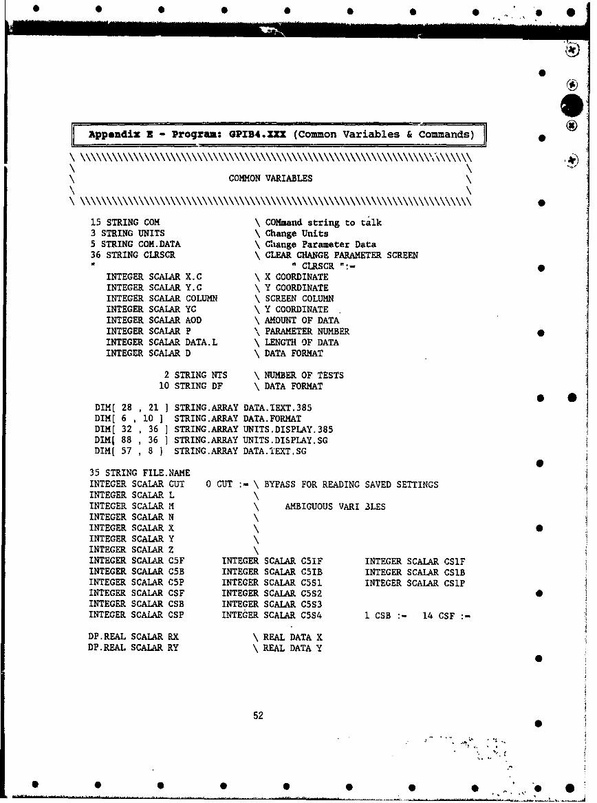
01
jjAppendix Z Program: GPIB4.XXX (Common Variables Comns
COMMON VARIABLES
15 STRING COM \ COMmand string to talk3 STRING UNITS \ Change Units5 STRING COM.DATA \ Change Parameter Data36 STRING CLRSCR \ CLEAR CHANGE PARAMETER SCREEN
" CLRSCR ":- 0INTEGER SCALAR X.C \ X COORDINATEINTEGER SCALAR Y.C \ Y COORDINATEINTEGER SCALAR COLUMN \ SCREEN COLUMNINTEGER SCALAR YC \ Y COORDINATEINTEGER SCALAR AOD \ AMOUNT OF DATAINTEGER SCALAR P \ PARAMETER NUMBERINTEGER SCALAR DATA.L \ LENGTH OF DATAINTEGER SCALAR DAA DATA FORMAT
2 STRING NTS \ NUMBER OF TESTS10 STRING DF \ DATA FORMAT • .1
DIM[ 28 , 21 ] STRING.ARRAY DATA.IEXT.385DIM( 6 , 10 ] STRING.ARRAY DATA.FORMATDIM[ 32 , 36 ] STRING.ARRAY UNITS.DISPLAY.385DIMS 88 , 36 ] STRING.ARRAY UNITS.DISPLAY.SGDIM[ 57 , 8 ] STRING.ARRAY DATA.TEXT.SG
35 STRING FILE.NAMEINTEGER SCALAR CUT 0 CUT :- \ BYPASS FOR READING SAVED SETTINGSINTEGER SCALAR L\INTEGER SCALAR M\ AMBIGUOUS VARI 3LESINTEGER SCALAR NINTEGER SCALAR X \INTEGER SCALAR YINTEGER SCALAR ZINTEGER SCALAR C5F INTEGER SCALAR C51F INTEGER SCALAR CS1FINTEGER SCALAR C5B INTEGER SCALAR C51B INTEGER SCALAR CSIBINTEGER SCALAR C5P INTEGER SCALAR C5SI INTEGER SCALAR CSIPINTEGER SCALAR CSF INTEGER SCALAR C5S2 0INTEGER SCALAR CSB INTEGER SCALAR C5S3INTEGER SCALAR CSP INTEGER SCALAR C5S4 I CSB "- 14 CSF :-
DP.REAL SCALAR RX \REAL DATA XDP.REAL SCALAR RY \ REAL DATA Y
52
0S
* * S..
0 0 00 0 00 0
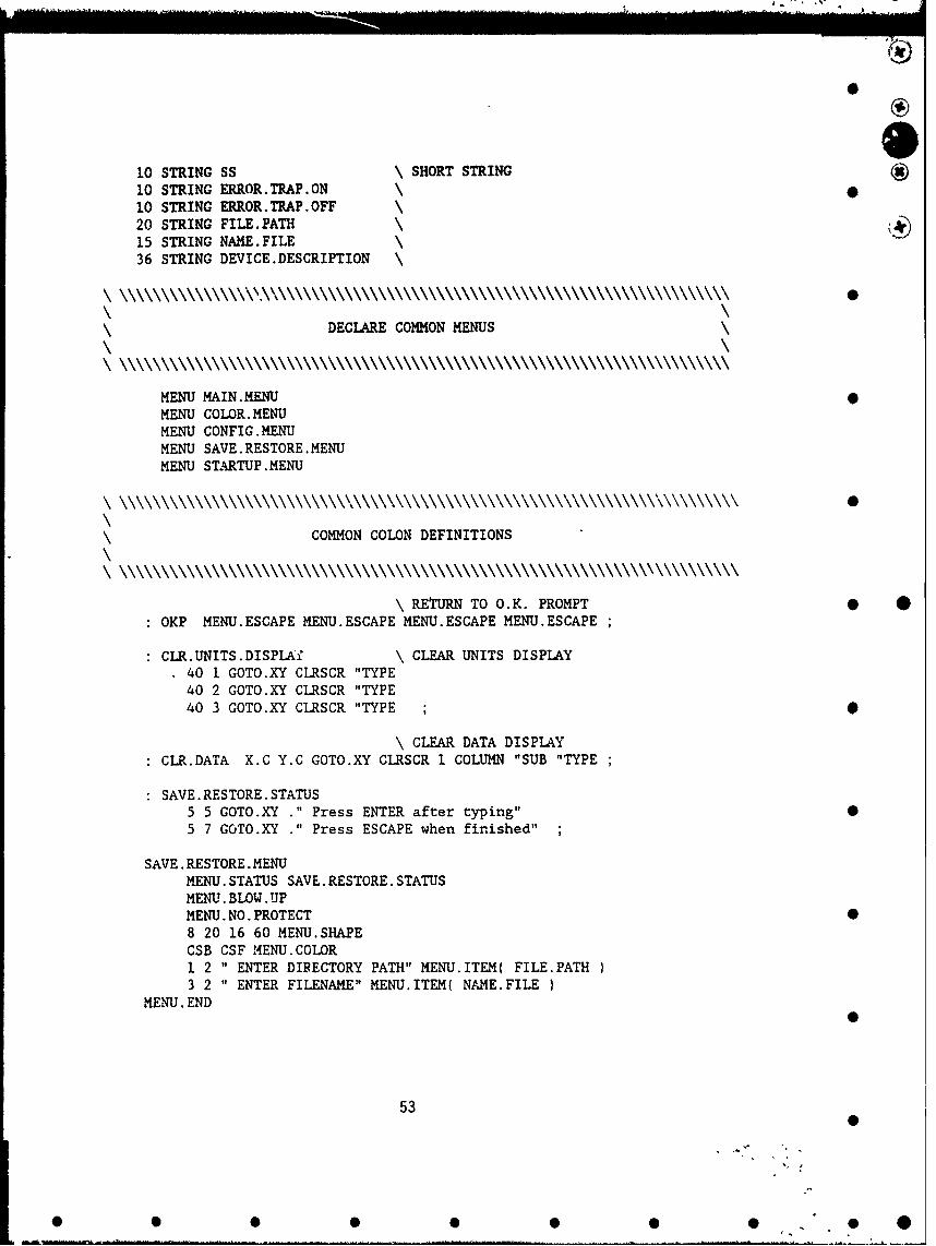
0
10 STRING SS \ SHORT STRING10 STRING ERROR.TRAP.ON10 STRING ERROR.TRAP.OFF20 STRING FILE.PATH15 STRING NAME.FILE36 STRING DEVICE.DESCRIPTION \
DECLARE COMMON MENUS
MENU MAIN.MENUMENU COLOR.MENUMENU CONFIG.MENUMENU SAVE.RESTORE.MENUMENU STARTUP. MENU
COMMON COLON DEFINITIONS
\ RETURN TO O.K. PROMPT * *OKP MENU.ESCAPE MENU.ESCAPE MENU.ESCAPE MENU.ESCAPE
CLR.UNITS.DISPLAY \ CLEAR UNITS DISPLAY40 1 GOTO.XY CLRSCR "TYPE40 2 GOTO.XY CLRSCR "TYPE40 3 GOTO.XY CLRSCR "TYPE ; 0
\ CLEAR DATA DISPLAY
CLR.DATA X.C Y.C GOTO.XY CLRSCR I COLUMN "SUB "TYPE
SAVE.RESTORE.STATUS5 5 GOTO.XY " Press ENTER after typing" 05 7 GOTO.XY " Press ESCAPE when finished"
SAVE. RESTORE. MENUMENU. STATUS SAVE.RESTORE. STATUSMENU. BLOW.UPMENU.NO.PROTECT •8 20 16 60 MENU.SHAPECSB CSF MENU.COLOR1 2 " ENTER DIRECTORY PATH" MENU.ITEM( FILE.PATH3 2 " ENTER FILENAME" MENU.ITEM( NrAME.FILE
MENU. END0
53
• • • •• • •0
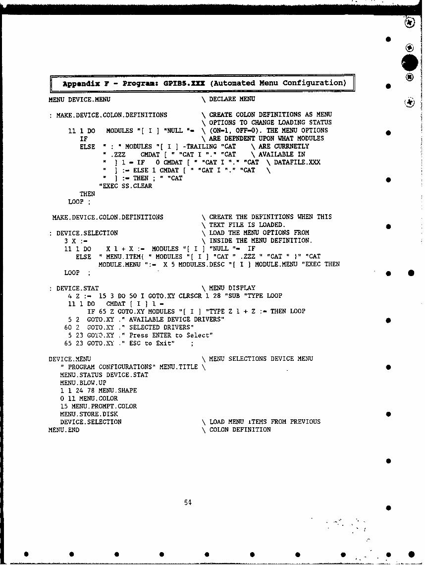
Appendix 7 - Program: GPIB5.XXX (Automated Menu Configuration) fMENU DEVICE.MENU \DECLARE MENU
MAKE.DEVICE.COLON.DEFINITIONS \CREATE COLON DEFINITIONS AS MENU\OPTIONS TO CHANGE LOADING STATUS
11 1 DO MODULES "f I -NULL "-\(ON-i, OFF-O). THE MENU OPTIONSIF \ARE DEPNDENT UPON WHAT MODULESELSE ":"MODULES "[I ] -TRAILING "CAT \ARE CURRNETLY
n.ZZZ CMDAT -CAT I -.- "CAT \AVAILABLE IN" 11 - IF 0 CMDAT -CAT I ".- -CAT \DATAFILE.XXXI -ELSE I CMDAT [""CAT I "1." "CAT \
" :THEN ""CAT"EXEC SS.CLEAR
THENLOOP
MAKE.DEVICE.COLON.DEFINITIONS \CREATE THE DEFINITIONS WHEN THIS\TEXT FILE IS LOADED.
DEVICE.SELECTION \LOAD THE MENU OPTIONS FROM3 X :- \INSIDE THE MENU DEFINITION.11 1 DO X 1 + X :- MODULES "[ I1 "NULL "-IF
ELSE " MENU.ITEM( " MODULES "[ I -CAT " ZZZ " "CAT " ""CAT
MODULE.MENU "-X 5 MODULES.DESC "[I ] MODULE.MENU "EXEC THEN
LOOP;
DEVICE.STAT \MENU DISPLAY4 Z :- 15 3 DO 50 1 GOTO.XY CLRSCR 1 28 "SUB "TYPE LOOP11i1DO CMDAT [I1I1-
IF 65 Z COTO.XY MODULES "[ I ] "TYPE Z 1 + Z :- THEN LOOP
5 2 GOTO.XY ."AVAILABLE DEVICE DRIVERS"60 2 CGOTO.XY ."SELECTED DRIVERS"5 23 GO'13.XY ."Press ENTER to Select"
65 23 GOTO.,XY ."ESC to Exit"
DEVICE. MENU \MENU SELECTIONS DEVICE MENU" PROGRAM CONFIGURATIONS" MENU.TITLE\0
MENU.STATUS DEVICE.STATMENU .BLOW .UP
1 1 24 78 MENU.SHAPEO 11 MENU.COLOR15 MENU. PROMPT. COLORMENU. STORE. DISKDEVICE.SELECTION \LOAD MENU iTEMS FROM PREVIOUS
MENU. END \COLON DEFINITION
00

: GPIB.D.C \ EDIT GPIB DEFINITIONSTEXT.EDIT GPIB3.XXX CRLOAD GPIB3.XXX
: MOUSE.SUPPORT \ EDIT ON/OFF MOUSE SUPPORT 01 CMDAT [1]- \ OPTION
IF 0 CMDAT [11] :-
ELSE 1 CMDAT [ 11]:-THEN
: SAVE.PROGRAM.CONFIG \ SAVE SELECTED OPTIONS35 20 GOTO.XY ." ENTER DOS ENTRY FILENAME " \ ENTER NEW FILE NAME" C:\ASYST " FILE.PATH ":- \ FOR EXECUTABLE ASYSTSAVE.RESTORE.MENU MENU.EXECUTE \ .COM FILEFILE.PATH -TRAILING " \" "CATNAME.FILE "CAT FILE.NAME ":-
1 CMDAT [ 12 ] :- \ ALTER FIRST.LOAD VALUEFILE.OPEN DATAF.ILE.XXX (SEE GPIB.XXX)
1 SUBFILE CMDAT ARRAY>FILE \ SAVE SELECTIONS INFILE.NAME 41 >COMMENT \ THE DATA FILE 0
FILE. CLOSELOAD GPIB.XXX ; \ RE-LOAD GPIB.XXX
CONFIG.STAT \ MENU DISPLAY14 FOREGROUND1 CMDAT fil]- 1 0
IF 35 10 GOTO.XY ." NOELSE 35 10 GOTO.XY ." YES" THEN
12 FOREGROUND 60 1 GOTO.XY ." DATE: " "DATE "TYPE 9 FOREGROUND40 16 GOTO.XY .' USAF PHOTONICS CENTER"40 17 GOTO.XY .' GRIFFIS AIR FORCE BASE"40 18 GOTO.XY ." ROME, NEW YORK" 010 FOREGROUND 60 21 GOTO.XY ." by Brian DeVaul" 11 FOREGROUND
CONFIG.MENU \ MAIN SELECTIONS MENU"1MENU CONFIGURATIONS" MENU.TTTLE \
MENU. STATUS CONFIG. STATMENU. BLOW.UP 01 1 24 78 MENU.SHAPE0 11 MENU.COLORMENU. STORE. DISK15 MENU.PROMPT.COLOR3 15 " RETURN TO MAIN MENU" MENU.ITEM( MENU.ESCAPE6 15 " DEVICE/PROGRAM SELECTION" MENU.ITEM( DEVICE.MENU ) 08 15 " GPIB DEVICE CONFIGURATION" MENU.ITEM( GPIB.D.C10 15 " MOUSE SUPPORT:" MENU.ITEM( MOUSE.SUPPORT )13 15 ".SAVE NEW SELECTIONS & REBOOT" MENU.ITEM( SAVE.PROGRAM.CONFIG
MENU. END
55
0 00 00 0 0

Appendix H - Program: 31Sll6A.XXX (HP - Signal Generator) *
HP8116A SIGNAL GENERATOR
A~.~AAAAA.~L.A******HP8116A VARIABLES AJ.AAAAAAAJA**
164 STRING CPS \ Current Parameter Settings13 STRING HILEV \ Hi Level setting13 STRING LOLEV \ Lo Level setting13 STRING AMPLT \ Amplitude13 STRING OFFSET \ Offset Value3 STRING UNITS \ Change Units
1 INTEGER SCALAR LOCK.OUT \ Keep track of Local Lock out condition33 STRING LOCK.TEXT \ Text displayed on Lock Out status1 LOCK.OUT :-
TOKEN DATA.SG \ Define blank variable SG dataTOKEN CPSI \ Integer Parameter Status array
\ Tokens are used to make use of\ any expanded memory available * O
\******************* DEFAULT GENERATOR PARAMETERS *
RELOAD.HP8116A \ RELOAD TOKEN DATA\ ATTEMPT TO USE EXPANDED MEMORY
e?EXP.MEM IF EXP.MEM> DATA.SG EXP.MEM> CPSI THENINTEGER DIM[ 5 , 22 1 UNNAMED.ARRAY BECOMES> DATA.SGINTEGER DIM[ 164 1 UNNAMED.ARRAY BECOMES> CPSI
" 4" UNITS.DISPLAY.SG "[ i I ":I"CT" UNITS.DISPLAY.SG "[ 5 ] ":- 0
" T " UNITS.DISPLAY.SG "[ 9 1 ":-
" H" UNITS.DISPLAY.SG "[ 13 ] ":-" W " UNITS.DISPLAY.SG "[ 17 ] ":-" L" UNITS.DISPLAY.SG "[ 21 ] ":-"H C" UNITS.DISPLAY.SG "[ 25 1 ":"I D UNITS.DISPLAY.SG "[ 29 ] ":-" A" UNITS.DISPLAY.SG "[ 33 ] ":" FRQ" UNITS.DISPLAY.SG "[ 37 ] ":-" DTY" UNITS.DISPLAY.SG "[ 41 ] ":" WID" UNITS.DISPLAY.SG "[ 45 1 ":-
"AMP" UNITS.DISPLAY.SG "[ 49 ] ":-
56
, 0
0 S 0 0 0 0 0 0 0. O
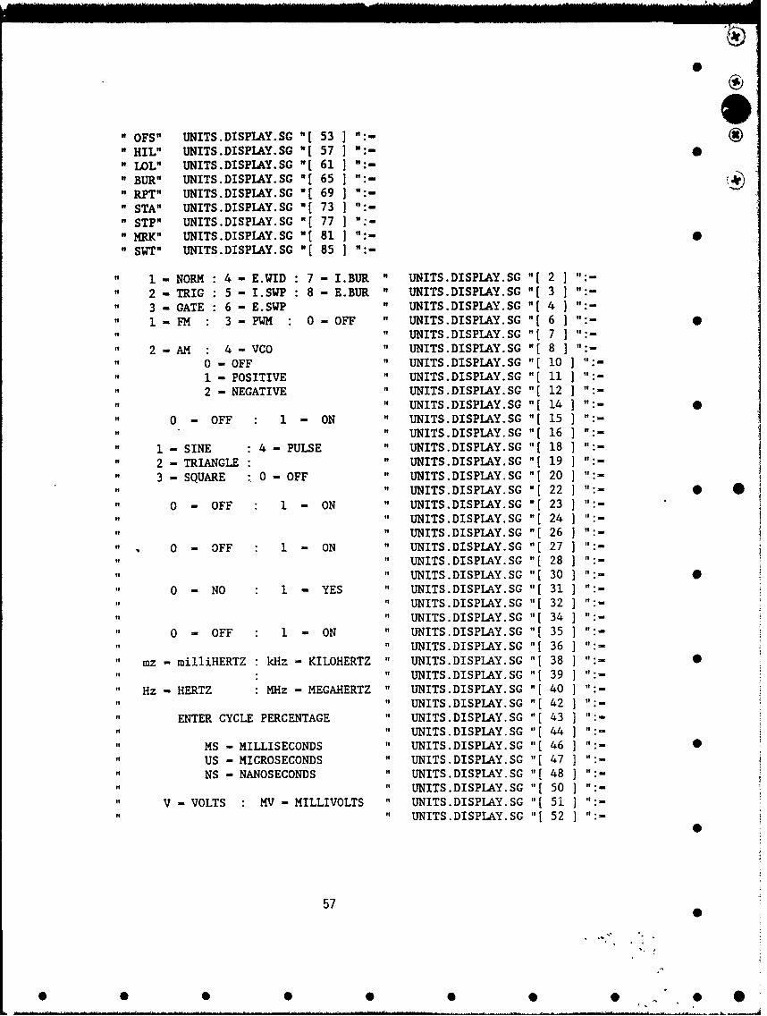
" OFS" UNITS.DISPIAY.SG Uf53] :
" HIL" UNITS.DISPLAY.SG "f57 J :
" LOL"' UNITS.DISPIAY.SG "[61]":
BUR" UNITS.DISPL&Y.SG "(65 ":
RPT"' UNITS.DISPLAY.SG Uf69]
STA" UNITS.DISPLAY.SG "E73STP" UNITS.DISPIAY.SG "f77] -
" m"I( UNITS.DISPLAY.SG WE81 ]W" SWT" UNITS.DISPLAY.SG '(851
1 - NORM 4 - E.WID 7 - I.BUR " UNITS.DISPIAY.SG WE2 ]2 - TRIG 5 - I.SWP 8 - E.BUR " UNITS.DISPIAY.SG WE3 ]i3 - GATE 6 - E.SWP W UNITS.DISPLAY.SG "[4 ]"I1 - FM 3 - PWM 0 - OFF " UNITS.DISPLAY.SG if6 1"
UNITS.DISPIAY.SG "[7
2 - AM 4 - VCO UNITS.DISPIAY.SG "E80 - OFF " UNITS.DISPLAY.SG "[101
1 - POSITIVE " UNITS.DISPLAY.SG if111":to2 - NEGATIVE " UNITS.DISPLAY.SG if12] -
to f UNITS.DISPLAY.SG if141 :
0 -OFF 1 -ON of UNITS.DISPLAY.SG "[15of UNITS.DISPLAY.SG if161 :
to 1-SINE :4 - PULSE of UNITS.DISPLAY.SG "[181 f
of 2-TRIANGLE : UNITS.DISPLAY.SG "f19 :
3 - SQUARE 0 - OFF to UNITS.DISPLAY.SG "1201 :
UNITS.DISPLAY.SG "[221t:* *0 - OFF 1 -ON to UNITS.DISPLAY.SG "[231":
tto UNITS.DISPI.AY.SG "E24)":toUNITS.DISPLAY.SG 'f26 "-
0-OFF I -ON " UNITS.DISPLAY.SG "[27] :
iIt UNITS.DISPLAY.SG "E281 :
if ~it UNITS.DISPLAY.SG if30 ":0
0 -NO 1I YES ~ ' UNITS.DISPLAY.SG "E31] -
itUNITS.DISPLAY.SG "[32 ]"=itto UNITS.DISPLAY.SG t[34
0s 0 OFF 1 -ON UNITS.DISPLAY.SG "1[ 35] :
iItJUNITS.DISPLAY.SG "[361
to mz -mi11iHERTZ kHz -KILOHERTZ " UNITS.DISPLAY.SG "E38 ":
UNITS.DISPLAY.SG "[39
to Hz -HERTZ M4Hz - MEGAHERTZ to UNITS.DISPLAY.SG "[40] :
tof UNITS.DISPLAY.SG "E421 :
itENTER CYCLE PERCENTAGE ~ ' UNITS.DISPLAY.SG "f43] :
UNITS.DISPLAY.SG "[44] :
atMS - MILLISECONDS of UNITS.DISPLAY.SG i[46 "-0
ofUS - MICROSECONDS of UNITS.DISPLAY.SG "E47] :
ItNS - NANOSECONDS to UNITS.DISPLAY.SG "[481":it to UNITS.DISPLAY.SG "[50] -
V -VOLTS MV -MILLIVOLTS if UNITS.DISPLAY.SG "E51] :
to it UNITS.DISPLAY.SG 'o[ 52 1'":-
57
00

0
"IOFS" GW OFFSET GR
1 LOCK.OUT - IF GEN LISTENER GO.TO.LOCAL \ ENABLE/DISABLE LOCAL LOCK OUT 0ELSE GEN LISTENER LOCAL.LOCKOUT THEN
\DISPLAY DATA
\ SOME PARAMETERS NEED A SECOND STRING, THE NEXT TWO SECTIONS DISPLAY\ ALL OF THE PARAMETERS PERTAINING TO THE SIGNAL GENERATOR
10 1 DO DATA.SG [ 1 , I ] DATA.SG [ 2 , I I GOTO.XYCPS DATA.SG [ 3 , I ] 4 "SUB "TYPE DATA.SG ( 1 , I ] 5 + Z :-
Z DATA.SG [ 2 , I ] GOTO.XYCPS DATA.SG [ , I DATA.SG [ 5 , I ] "SUB "TYPE LOOP
19 10 DO CPS DATA.SG [ 3 , I ] 1 "SUB 0 "NUMBER X :-I 9 - 6 * 5 Z :- X 6 < IF Z X + Z :- ELSE 49 X + Z :-THEN DATA.SG [ 1 ,I I DATA.SG [ 2 , I ] GOTO.XY CLRSCR 1 10 "SUB"TYPE DATA.SG I , I ] DATA.SG [ 2 , I ] GOTO.XYDATA.TEXT.SG "[ Z ] "TYPE SC
LOOP\ /\ THIS SECTION DISPLAYS MISC. PARAMETERS NOT FOUND IN THE CPS ARRAY /
5 1/65 12 GOTO.XY HILEV 5 8 "SUB "TYPE \ HI LEVEL65 13 GOTO.XY LOLEV 5 8 "SUB "TYPE \ LOW LEVEL •
20 10 GOTO.XY AMPLT 5 8 "SUB "TYPE \ AMPLITUDE27 10 GOTO.XY AMPLT 12 2 "SUB "TYPE20 11 GOTO.XY OFFSET 5 8 "SUB "TYPE \ OFFSET
C5S3 FOREGROUND 42 5 GOTO.XY LOCK.TEXT "TYPE0
**************************** TEXT **************************************
HP8116A.STATUS C5S1 FOREGROUNDDISPLAY.DATA C5S2 FOREGROUND26 8 GOTO.XY ." CURRENT PARAMETER SETTINGS"0 8 GOTO.XY ." *******************"58 8 GOTO. XY ." ********************"1 10 GOTO.XY ." Amplitude:" 40 10 GOTO.XY ." Output Disabled:"1 11 GOTO.XY " Offset:" 40 11 GOTO.XY " Autovernier:"1 12 GOTO.XY " Operating Mode:" 40 12 GOTO.XY " High Level"1 13 GOTO.XY " Control Mode:" 40 13 GOTO.XY " Low Level:"1 14 GOTO.XY " Trigger Slope:" 40 14 GOTO.XY " Burst Number:"1 15 GOTO.XY " Haversine(-90):" 40 15 GOTO.XY " Repetition Rate:"1 16 GOTO.XY " Waveform:" 40 16 GOTO.A/ " Sweaep Start Freq. :"
1 17 GOTO.XY " Frequency:" 40 17 GOTO.XY " Sweep Stop Freq. :"
58
• • •• • • •• •0
S... . . . . .. .. ........ .. . . .. 0• 7 0i• "

UNITS.DI52ILAY.SG If 54]"-V -VOLTS MV -MILLIVOLTS " UNITS.DISPLAY.SG "t55] :
UNITS.DISPLAY.SG "t56 ]UIIf UNITS.DISPLAY.SG "t58]":
IfENTER AMOUNT OF VOLTS If UNITS.DISPLAY.SG i[59]
IfUNITS.DISPLAY.SG "[60] :
If Uf UNITS.DISPT.AY.SG "t62] :
IfENTER AMOUNT OF VOLTS If UNITS.DISPLAY.SG Uf63 ":0
U Uf UNITS.DISPLAY.SG "t64 ":
It" UNITS.DISPLAY.SG "t66 ":
UENTER NUMBER OF BURSTS It UNITS.DISPLAY.SG Uf67]":
If Uo UNITS.DISPLAY.SG Ift 68 1UIf UNITS.DISPLAY.SG Uf701 :
It ENTER REPETATIVE RATE OF SWEEPS If UNITS.DISPLAY.SG "f71] :
1, Uf UNITS.DISPLAY.SG "t721of mz - mi11iHERTZ kHz - KILOHERTZ '1 UNITS.DISPLAY.SG Uf74]ii
Ito UNITS.DISPIAY.SG "t75] :
I. Hz - HERTZ MHz - MEGAHERTZ " UNITS.DISPLAY.SG "[76]iimz - mi11iHERTZ kliz - KILOHERTZ If UNITS.DISPLAY.SG "t78 1i:
If UNITS.DISPIAY.SG "t79 ]UU Hz - HERTZ MHz - M4EGAHERTZ If UNITS.DISPLAY.SG "t80] i
U mz - mi11iHERTZ kHz - KILOHERTZ U UNITS.DISPLAY.SG "t821":U ~to UNITS.DISPLAY.SG Ut831":
Hz - HERTZ MHz - MEGAHERTZ U" UNITS.DISPLAY.SG Ut841":
Ut Uf UNITS.DISPLAY.SG U[861U:* *If S - SECONDS :MS - MILLISECONDS it UNITS.DISPLAY.SG Uf87]i:
UIf UNITS.DISPLAY.SG "t881":
U U DATA.TEXT.SG 't1 ] U iUDATA.TEXT.SG tIf[ 29] :
If NORM U DATA.TEXT.SG Uf2 of 'I DATA.TEXT.SG Ift 301 i
IfTRIG U DATA.TEXT.SG Uf3 ] OFF "DATA.TEXT.SG U[31 ":
If GATE If DATA.TEXT.SG i[4 ] U 'ON UDATA.TEXT.SG i[32] ":
E.WID If DATA.TEXT.SG i[5 It:- itIf DATA.TEXT.SG If 33] t
I.SWP "DATA.TEXT.SG hf6 It:- ttI DATA.TEXT.SG 341i:IfOFF U DATA.TEXT.SG If[ 7 1i:- of If DATA.TEXT.SG tf35]":FýM 11 IfATX.S f81 : DATA.TEXT.SG If [36 i:
AM If DATA.TEXT.SG Ut9 1 Ii:- OFF If DATA.TEXT.SG If[ 37 ] :ItPWM IfDATA.TEXT.SG tf10 I,: If ON I' DATA.TEXT.SG If[ 38 '1i:-
11VCO DATA.TEXT.SG If[ 11 1Ii:- "lI DATA.TEXT.SG i[39
iIfDATA.TEXT.SG Ift 12 1 i:- " I DATA.TEXT.SG "t40 ":
IfOFF If DATA.TEXT.SG tt13 ': 1 Iif DATA.TEXT.SG Ut41 1i:IfPOSITIVE" DATA.TEXT.SG Uf14 It U iiIt DATA.TEXT.SG Ut42]ti
itNEGATIVE" DATA.TEXT.SG Ut15 ] i iOFF DATA.TEXT.SG "t43 ] 0
UUDATA.TEXT.SG "t16 1i: ON UDATA.TEXT.SG If[ 44 1 ":-
Uf DATA.TEXT.SG "t17 If: DATA.TEXT.SG "t 45 1":-IfDATA..TEXT.SG If[ 18 1't:- If DATA.TEXT.SG If[ 46 ] i:-11DATA.TEXT.SG "( 19 1 :"DATA.TEXT.SG Ift 47]ti
IfSINE " DATA.TEXT.SG Ift 20 1 i tUDATA.TEXT.SG If[ 48 tt
UTRIANGLE" DATA.TEXT.SG "t 21 1': If NO If DATA.TEXT.SG "( 491 :
590
0 0 0 0000 0
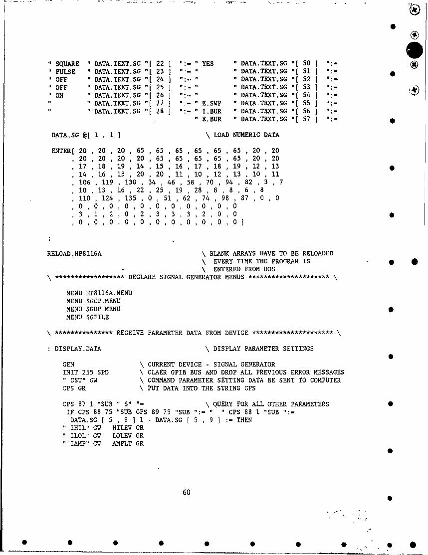
0
" SQUARE " DATA.TEXT.SC "[ 22 ] ":- " YES " DATA.TEXT.SG "[ 50 ] ":-
" PULSE " DATA.TEXT.SG "[ 23 ] "- " " DATA.TEXT.SG "[ 51 ] ":- •" OFF " DATA.TEXT.SG "[ 24 ] ":- " " DATA.TEXT.SG "[ 52 ] ":-" OFF " DATA.TEXT.SG "[ 25 ] ":- " DATA.TEXT.SG "[ 53 "" ON " DATA.TEXT.SG "[ 26 ] ":,- " " DATA.TEXT.SG "[ 54 ] ":-
" DATA.TEXT.SG "[ 27 ] ".- " E.SWP " DATA.TEXT.SG "[ 55 ] ":-" DATA.TEXT.SG "[ 28 ] ":- " I.BUR " DATA.TEXT.SG "[ 56 ] ":-
"E.BUR " DATA.TEXT.SG '[ 57 ] ":-
DATA.SG @[ 1 , 1 ] \ LOAD NUMERIC DATA
ENTER[ 20 , 20 , 20 , 65 , 65 , 65 , 65 , 65 , 65 , 20 , 2020 , 20 , 20 , 20 , 65 , 65 , 65 , 65 , 65 , 20 , 2017 ,18 ,19 ,14 ,15 ,16 ,17 ,18 ,19 ,12 ,1314 , 16 , 15 , 20 , 20 , 11 , 10 , 12 , 13 , 10 , 11106, 119 , 130 , 34 , 46 , 58 , 70 , 94 , 82 , 3 , 710 13 , 16 , 22 , 25 , 19 , 28 , 8 , 8 6 , 8110 124 ,135 , 0 , 51 , 62 , 74 , 98 87 0 , 0
3 ,1, 2, 0, 2 ,3 ,3,3, 2 ,0, 00, ,0, , 0,0 ,0 , O, 0 , O, O]
RELOAD.HP8116A \ BLANK ARRAYS HAVE TO BE RELOADED\ EVERY TIME THE PROGRAM IS * *\ ENTERED FROM DOS.
****************** DECLARE SIGNAL GENERATOR MENUS *********************
MENU HP8116A.MENUMENU SGCP.MENUMENU SGDP.MENUMENU SGFILE
*************** RECEIVE PARAMETER DATA FROM DEVICE *********************
DISPLAY.DATA \ DISPLAY PARAMETER SETTINGS
GEN \ CURRENT DEVICE - SIGNAL GENERATORINIT 255 SPD \ CLAER GPIB BUS AND DROP ALL PREVIOUS ERROR MESSAGES" CST" GW \ COMMAND PARAMETER SETTING DATA BE SENT TO COMPUTERCPS GR \ PUT DATA INTO THE STRING CPS
CPS 87 1 "SUB " S" "- \ QUERY FOR ALL OTHER PARAMETERSIF CPS 88 75 "SUB CPS 89 75 "SUB ":- " " CPS 88 1 "SUB ":-
DATA.SG [ 5 , 9 ] 1 - DATA.SG [ 5 , 9 1 :-THEN
" IHIL" GW HILEV GR" ILOL" GW LOLEV GR" IAMP" GW AMPLT GR
60
• • •• • • • " 60S. . . . .. . . ... . .. . . ... . .. .. . . . . . .. • - . ..
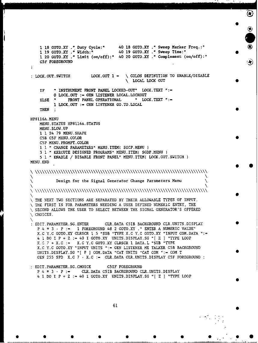
1 18 GOTO.XY ." Duty Cycle:" 40 18 GOTO.XY ." Sweep Marker Freq.:"1 19 GOTO.XY ." Width:" 40 19 GOTO.XY ." Sweep Time:"1 20 GOTO.XY ." Limit (on/off):" 40 20 GOTO.XY ." Complement (on/off):"C5F FOREGROUND
LOCK.OUT.SWITCH LOCK.OUT 1 - \ COLON DEFINITION TO ENABLE/DISABLE\ LOCAL LOCK OUT
IF " INSTRUMENT FRONT PANEL LOCKED-OUT" LOCK.TEXT ":-
0 LOCK.OUT :- GEN LISTENER LOCAL.LOCKOUTELSE " FRONT PANEL OPERATIONAL " LOCK. TEXT ":-
1 LOCK.OUT :- GEN LISTENER GO.TO.LOCALTHEN ;
HP8116A.MENUMENU.STATUS HP8116A. STATUSMENU. BLOW. UP1 1 24 79 MENU.SHAPEC5B C5F MENU.COLOR 0C5P MENU. PROMPT. COLOR1 1 " CHANGE PARAMETERS" MENU.ITEM( SGCP.MENU3 1 " EXECUTE DESIGNED PROGRAMS" MENU.ITEMt SGDP.MENU I5 1 " ENABLE / DISABLE FRONT PANEL" MENU.ITEM( LOCK.OUT.SWITCH
MENU. END
\ \
Design for the Signal Generator Change Parameters Menu
\ THE NEXT TWO SECTIONS ARE SEPARATED BY THEIR ALLOWABLE TYPES OF INPUT.\ THE FIRST IS FOR PARAMETERS NEEDING A USER DEFINED NUMERIC ENTRY, THE\ SECOND ALLOWS THE USER TO SELECT BETWEEN THE SIGNAL GENERATOR'S OFFERED\ CHOICES.
EDIT.PARAMETER.SG.ENTER CLR.DATA C51B BACKGROUND CLR.UNITS.DISPLAY 0P 4 * 3 - P :- 1 FOREGROUND 48 2 GOTO.XY ." ENTER A NUMERIC VALUE"
X.C Y.C GOTO.XY CLRSCR 1 5 "SUB "TYPE X.C Y.C GOTO.XY "INPUT COM.DATA ":=
4 1 DO I P + Z :- 40 1 GOTO.XY UNITS.DISPLAY.SG "[ Z ] "TYPE LOOPX.C 7 + X.C :- X.C Y.C GOTO.XY CLRSCR I DATA.L "SUB "TYPEX.C Y.C GOTO.XY "INPUT UNITS ":- GEN LISTENER ME TALKER C5B BACKGROUNDUNITS.DISPLAY.SG "[ P I COM.DATA "CAT UNITS "CAT COM ":- COM T 0
GEN 255 SPD X.C 7 - X.C :- CLR.DATA CLR.UNITS.DISPLAY C5F FOREGROUND
"EDIT.PARAMETER.SG.CHOICE C51F FOREGROUNDP 4 * 3 - P :- CLR.DATA C51B BACKGROUND CLR.UNITS.DISPLAY
4 1 DO I P + Z :- 40 1 GOTO.XY UNITS.DISPLAY.SG "[ Z ] "TYPE LOOP
61 •
0 0 0 00 S 0" *0

0
X.C Y.,C GOTO.XY CLRSCR 1 DATA.L "SUB "TYPEX.C Y.C GOTO.XY "INPUT COM.DATA ":- GEN LISTENER HE TALKER C5B BACKGROUNDUNITS.DISPLAY.SG "[ P I COM.DATA "CAT UNITS "CAT COM ":- COM T
GEN 255 SPD CLR.DATA CLR.UNITS.DISPLAY " " UNITS ":- C5F FOREGROUND ;
*************************** PARAMETERS ** ****************** /
\ EACH PARAMETER HAS IT'S OWN COLON DEFINITION FOR THE MENU. ITEM SELECTION
\ AND USES THE DEFINITION TO SET X,Y COORDINATES, DATA LENGTH, PLACE IN\ DATA ARRAY AND WHICH PARAMETER CHANGING COLON DEFINITION (ENTER OR CHOICE).
OPMODE \ .. "............. ' \ OPERATING MODE20 X.C :- 12 COLUMN :- 1 P :-
12 Y.C :- 1 DATA.L :- EDIT.PARAMETER.SG.CHOICECTM * \ CONTROL MODE
20 X.C :- 12 COLUMN :- 2 P .-
13 Y.C :- 1 DATA.L :- EDIT.PARAMETER.SG.CHOICETS ** \ TRIGGER SLOPE
20 X.C :- 12 COLUMN :- 3 P :-14 Y.C :- 1 DATA.L :- EDIT.PARAMETER.SG.CHOICE
HAV ** *********\ HAVERSINE20 X.C :- 12 COLUMN :- 4 P :-
15 Y.C :- 1 DATA.L :- EDIT.PARAMETER.SG.CHOICE ;WAVEFORM . .**************************** ***
20 X.C :- 12 COLUMN :- 5 P :- •16 Y.C :- 1 DATA.L :- EDIT.PARAMETER.SG.CHOICE
: LIMIT ******************************** \20 X.C :- 12 COLUMN :- 6 P :-20 Y.C :- 1 DATA.L EDIT.PARAMETER.SG.CHOICE
: COMPL \* * ****** ** \ COMPLIMENT65 X.C :- 12 COLUMN :- 7 P :-20 Y.C :- i DATA.L :- EDIT.PARAMETER.SG.CHOICE ;
: DISABLE * \ DISABLE OUTPUT
65 X.C :- 12 COLUMN :" 8 P "-10 Y.C :- 1 DATA.L EDIT.PARAMETER.SG.CHOICE
: AUTO ************************* \ AUTOVERNIER65 X.C :- 12 COLUMN :- 9 P :-11 Y.C :- 1 DATA.L :- EDIT.PARAMETER.SG.CHOICE
FREQ * \ FREQUENCY20 X.C :- 12 COLUMN :- 10 P :-17 Y.C :- 3 DATA.L :- EDIT.PARAMETER.SG.ENTER
DTY.CYCLE \ ***************************** \ DUTY CYCLE20 X.C :- 12 COLUMN :- 11 P " %" UNITS ": 018 Y.C :- 4 DAK.A.L :- EDIT.PARAMETER.SG.CHOICE
WIDTH ****** \ SIGNAL WIDTH20 X.C :- 12 COLUMN :- 12 P :-19 Y.C :- 2 DATA.L :- EDIT.PARAMETER.SG.ENTER
AMPL ******************************** \ AMPLITUDE
62
00• • •• • • •• •0

0A
20 X.C :- 12 COLUMN :- 13 P :-10 Y.C :- 2 DATA.L :- EDIT.PARAMETER.SG.ENTER ;
OFST * \ OFFSET20 X.C :- 12 COLUMN :- 14 P :-11 Y.C :- 2 DATA.L :- EDIT.PARAMETER.SG.ENTER ; -
HILL ******** --****--********* \ HIGH LEVEL65 X.C :- 12 COLUMN :- 15 P :- " V" UNITS ":-
12 Y.C :- 4 DATA.L :- EDIT.PARAMETER.SG.CHOICE ;LOLL * \ LOW LEVEL
65 X.C :- 12 COLUMN - 16 P :- " V" UNITS ":-13 Y.C :- 4 DATA.L :- EDIT.PARAMETER.SG.CHOICE
BURST# ***** \ BURST NUMBER65 X.C :- 12 COLUMN :- 17 P :- " #" UNITS ":-14 Y.C :- 4 DATA.L : EDIT.PARAMETER.SG.CHOICE ;
REP.RAT *********** \ REPETITION RATE65 X.C :- 12 COLUMN :- 18 P :-
15 Y.C 2 DATA.L :- EDIT.PARAMETER.SG.ENTERSWPST. FREQ \ ***************************** \ SWEEP START FREQUENCY
65 X.C :- 12 COLUMN :- 19 P :-
16 Y.C :- 3 DATA.L "- EDIT.PARAMETER.SG.ENTER ;SWPSTOP.FREQ \ ****** ************* \ SWEEP STOP FREQUENCY
65 X.C :- 12 COLUMN :- 20 P :-
17 Y.C :- 3 DATA.L :- EDIT.PARAMETER.SG.ENTERSWPMRK. FREQ \ ***--********************** \ SWEEP MARKER FREQUENCY
65 X.C :- 12 COLUMN :- 21 P :-18 Y.C :- 3 DATA.L :- EDIT.PARAMETER.SG.ENTER ; * *
SWPTIME \ \ SWEEP TIME65 X.C :- 12 COLUMN 22 P :-19 Y.C :- 2 DATA.L :- EDIT.PARAMETER.SG.ENTER
**************** SIGNAL GENERATOR PARAMETERS MENU ********************* /
SGCP.STAT C5S4 FOREGROUND \ CHANGE PARAMETERS MENU DISPLAY1 1 GOTO.XY ." CHANGE PARAMETERS"1 3 GOTO.XY ." EXECUTE DESIGNED PROGRAMS"1 5 GOTO.XY *" ENABLE / DISABLE FRONT PANEL"26 8 GOTO.XY *" CURRENT PARAMETER SETTINGS"0 8 GOTO.XY " ********************58 8 GOTO.XY ." *********************13 FOREGROUND DISPLAY.DATA 11 FOREGROUND " " UNITS ":-
SGCP. MENU \ CHANGE PARAMETERS MENUMENU.STATUS SGCP. STAT1 1 24 79 MENU.SHAPEC5B C5F MENU.COLORC5P MENU. PROMPT. COLOR10 1 " Amplitude:" MENU.ITEM( AMPL11 1 " Offset:" MENU.ITEM( OFST )12 1 " Operating Mode:" MENU.ITEM( OPMODE
63
0
0 0 0 0 0 0 0! " 0

S
13 1 " Control Mode:" MENU.ITEM( CTM )14 1 " Trigger Slope:" MFNU.ITEM( TS )15 1 " Haversine(-90):" t1ENU.ITEM( HAV16 1 " Waveform:" MENU.ITEM{ WAVEFORM17 1 " Frequency:" MENU.ITEM( FREQ )18 1 " Duty Cycle:" MENU.ITEM{ DTY.CYCLE )19 1 " Width:" MENU.ITEM( WIDTH )20 1 " Limit (on/off):" MENU.ITEM( LIMIT )10 40 " Output Disabled:" MENU. ;TEM{ DISABLE11 40 Autovernier:" MENU.ITEM AUTO12 40 " High Level" MENU.ITEM( LILL13 40 " Low Level:" MENU.ITEK( LOLL14 40 " Burst Number:" MENU.I•.M{ BURST#15 40 " Repetition Rate:" MENU.ITEM( REP.RAT }16 40 " Sweep Start Freq.:" MENU.ITEM{ SWPST.FREQ17 40 " Sweep Stop Freq.:" MENU.ITEM( SWPSTOP.FREQ18 40 " Sweep Marker Freq. :" MENU.ITEM( SWPMRK.FREQ }19 40 " Sweep Time:" MENU.ITEM( ýWPTIME )20 40 " Complement (on/off):" MENU.ITEM( COMPL
MENU. END
Execute Specific Parameter Cbanges
SCS \ SAVE CURRENT SETTINGSSAVE.RESTORE.MENU MENU.EXECUTE \ CHOOSE FILE NAMEFILE.PATH " ' "CAT NAME.FILE "CAT \FILE.NAME ":-CPS CPSI ">ARRAY \ CONVERT STRING TO INTEGER FORMATFILE.TEMPLATE
INTEGER DIM' 164 ] SUBFILE \ CREATE FILEENDFILE.NAME DEFER> FILE.CREATEFILE.NAME DEFER> FILE.OPEN \I SUBFILE CPSI ARRAY>FILE \ INPUT ARRAY DATA INTO FILEFILE.CLOSE MENU.ESCAPE ;
RSS \ RESTORE SAVED SETTINGSSAVE.RESTORE.MENU MENU.EXECUTE \ CHOOSE FILE NAME •FILE.PATH " \" "CAT NAME.FILE "CAT \FILE.NAME ":FILE.NAME DEFER> FILE.OPENI SUBFILE CPSI FILE>ARRAY \ DUMP FILE DATA INTO INTEGER ARRAYFILE.CLOSE
64
• • • •• • •

CPSI CPS ARRAY>" \ CONVERT INTEGER ARRAY INTO STRINGGENCPS 2 164 "SUB GW \ SEND STRING TO SIGNAL GENERATOR255 SPD 5 CUT :- \ TO RESTORE SAVED PARAMETERSMENU.ESCAPE ;
SGDP.MENU \ SAVE & RESTORE PARAMETERS MENU2 50 6 76 MENU.SHAPECSIB CS1F MENU.COLORCSIP MENU. PROMPT. COLOR1 2 " GO TO THE O.K. PROMPT" MENU.ITEM{ OKP )2 2 " SAVE CURRENT SETTINGS" MENU.ITEM( SCS )3 2 " READ SAVED SETTINGS" MENU.ITEM( RSS •
MENU. END
6
* 0
0
65
• • •• • • •• •S
* .. . . . . . . . . . . . . . . . . .. . . .... . .. .. . o - . 0 . 0
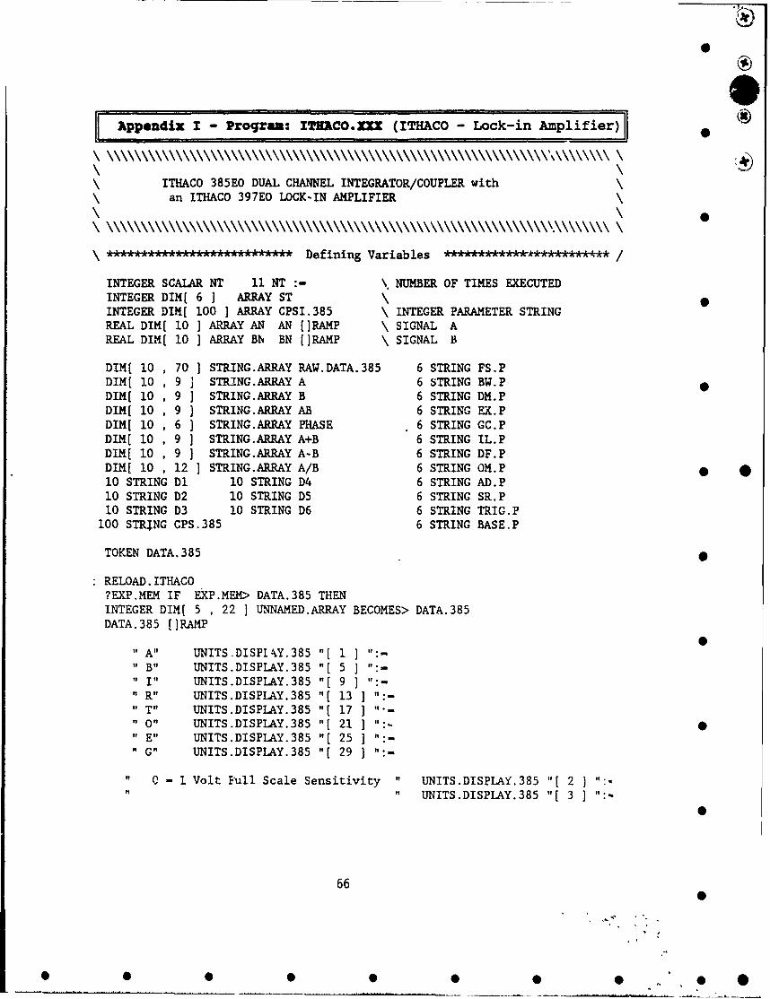
IEK ppendix I - Proqzam: ITRACO.XXx (ITHACO - Lock-in Amplifier) •
ITHACO 385E0 DUAL CHANNEL INTEGRATOR/COUPLER withan ITHACO 397EO LOCK-IN AMPLIFIER
\ kA•h*AA•kAA.I:k•A.L'.A*** Defining Variables *AeA******k*********** /
INTEGER SCALAR NT 11 NT :- \ NUMBER OF TIMES EXECUTEDINTEGER DIM[ 6 ] ARRAY STINTEGER DIM[ 100 ] ARRAY CPSI.385 \ INTEGER PARAMETER STRINGREAL DIM[ 10 ] ARRAY AN AN (]RAMP \ SIGNAL AREAL DIM[ 10 ] ARRAY Bb, BN []RAMP \ SIGNAL B
DIM[ 10 70 ] STRING.ARRAY RAW.DATA. 385 6 STRING FS.PDIM[ 10 9 ] STRING.ARRAY A 6 STRING BW.PDIM[ 10 9 ] STRING.ARRAY B 6 STRING DM.PDIM[ 10 9 ] STRING.ARRAY AB 6 STRING EX.PDIM[ 10 6 ] STRING.ARRAY PHASE 6 STRING GC.PDIM[ 10 9 ] STRING.ARRAY A+B 6 STRING IL.PDIM[ 10 9 ] STRING.ARRAY A-B 6 STRING DF.PDIM[ 10 12 ] STRING.ARRAY A/B 6 STRING OM.P * *10 STRING D1 10 STRING D4 6 STRING AD.P10 STRING D2 10 STRING D5 6 STRING SR.P10 STRING D3 10 STRING D6 6 STRING TRIG.P
100 STRTNG CPS.385 6 STRING BASE.P
TOKEN DATA. 385
RELOAD. ITHACO?EXP.MEM IF EXP.MEM> DATA.385 THENINTEGER DIM[ 5 , 22 ] UNNAMED.ARRAY BECOMES> DATA. 385DATA.385 []RAMP
0" A" UNITS.DISPlkY.385 "1 1 ] ":-" B" UNITS.DISPLAY.385 "[ 5 ] ":-
" I" UNITS.DISPLAY.385 "[ 9 ] ":-" R" UNITS.DISPLAY.385 "[ 13 ] ":-" T" UNITS.DISPLAY.385 "[ 17 ] '-" o" UNITS.DISPLAY.385 "[ 21 ] ":" E" UNITS.DISPLAY.385 "[ 25 1 ":-" G" UNITS.DISPLAY.385 "[ 29 ] ":-
" 0 - 1 Volt Full Scale Sensitivity " UNITS.DISPLAY.385 "[ 2 "
"UNITS.DISPLAY.385 "[ 3 ] ":-
66
S0
S S S S 5 0 0 0 0

-10 Volts Full Scale Sensitivity " UNITS.DISPLAY.385 "[4 ] '
It0 -2 Hertz " UNITS.DISPLAY.385 "(6] '
UNITS.DISPLAY.385 "(7] :
1 - 20 Hertz " tNITS.DISPIAY.385 "(8 I:
" Enter the Integration Length UtINITS.DISPLAY.385 110 ":
ItUNITS.DISPLAY.385 ~[11 ]':in 1/60 second increments UNITS.DISPIAY.385 i[121 :
Enter the Autorange Delay " UITS.DISPIAY.385 S[14] I.
UNITS.DISPLAY.385 "[15 -
in 1/60 second increments It UNITS.DISFLAY,235 "f16] :
n T - TTL Triggering Input " UNITS.DISPLAY.385 "t18]":B - GPIB Triggering " UNITS.DISPI.AY.385 "[19] *
I - INTERNAL :E -EXTERNAL(T & B) UNITS.DISPIAY.385 "[201it UNITS.DISPLAY.385 ":22 ]"
C -Continuous B - Burst " UNITS.DISPLAY.385 "[23 1"UNITS.DISPLAY.385 "[241 *
0 -No Expansion " UNITS.DISPLAY.385 "[261 :
UNITS.DISPLAY.385 "t27] t
1-Expansion x 10 " UNITS.DISPLAY.385 "[28
0 - Off 3 - 1 mV 6 - I V UJNITS.DISPLAY.385 i[30 1:1 -l10uV 4 -l10mV '~UNITS.DISPLAY.385 I[311tt
2 - 100 uV 5 - 100 WV 7 - Off ~' UNITS.DISPLAY.385 "[32] :
DATA.TEXT.385 I[11 :
DATA.TEXT.385 "[2 ":
ItDATA.TEXT.385 ~t31 :* *DATA.TEXT.385 "[41 -
DATA.TEXT.385 "[5] -
DATA.TEXT.385 i[6 "-
DATA.TEXT.385 "[7] :
itDATA.TEXT.385 "t81 :
tisi DK.A.TEXT.385 "[91 :
is DATA.TEXT.385 t- 101 :
it DATA.TEXT.385 '(111 :
itDATA.TEXT.385 "[12 :
it DATA.TEXT.385 t(131":
ItDATA.TEXT.385 i[141 -
DATA.TEXT.385 i[15 ":0
DATA.TEXT.385 "(161 :
DATA.TEXT.385 t[171
it DATA.TEXT.385 "[18 :
DATA.TEXT.38j 19] :
DATA.TEXT.385 '[20 1 ":-
DATA.TEXT.385 '[21] :
DATA.TEXT.385 "t221 :
DATA.TEXT.385 i[23] :
DATA.TEXT.385 i[24 :
DATA.TEXT.385 "t251 :
DATA.TEXT.3E5 i(261 :
67

A
" DATA.TEXT.385 "[ 27 ] ":-" DATA.TEXT.385 "[ 28 ] ":- S
" A " DATA.FORMAT "[ 1 ] -:-" B " DATA.FORMAT "[ 2 ]" VS & PA" DATA.FORMAT "[ 3 ] ":-
" A+B " DATA.FORMAT "[ 4 ] ":-" A-B " DATA.FORMAT "[ 5 ] ":-
" A/B " DATA.FORMAT "[ 6 ] ":-
RELOAD. ITHACO
\*,* * , Defining Menus 0*************** /
MENU ITHACO. MENUMENU ITHACO.MENU2MENU ITHACO.MENU3MENU ITHACO. MENU4MENU ITHACO. MENU5 •MENU ITHACO.MENU6MENU DF.MENU.385
***************** RECEIVE PARAMETER DATA FROM DEVICE ****************** /
RECEIVE.DATA.385 0
ITH385 \ CURRENT DEVICE - ITHACO 385EO50 MSEC.DELAY255 SPD" ?", GW \ SEND PARAMETER SETTING DATA TO COMPUTERCPS.385 GR \ PUT DATA INTO THE PARAMETER STRING
DISPLAY.DATA.385
RECEIVE. DATA. 385
**************************** DISPLAY DATA ***************************** /
CPS.385 2 1 "SUB FS.P ":- \ FULL SCALEFS.P " 0" "- IF 20 14 GOTO.XY ." 1" THEN \ SENSITIVITYFS.P " I" "- IF 20 14 GOTO.XY 1." 0" THEN23 14 GOTO.XY ." Volt Full Scale"
CPS.385 5 1 "SUB BW.P ":- \ BANDWIDTH
BW.P " 0" "- IF 20 15 GOTO.-" 2" THEN x100BW.P " 1" "- IF 20 15 GOTO., 20" THEN27 15 GOTO.XY ." Hertz"
CPS.385 18 4 "SUB 0 "NUMBER \ INTEGRATION LENGTH 0
68 0
0 0 0 0 0 00 0

0
20 16 GOTO.XY\27 16 GOTO.XY " 1/60 SEC" \
CPS.385 30 3 "SUB 0 "NUMBER \ AUTORANGE DELAY20 17 GOTO.XY .27 17 GOTO.XY ." 1/60 SEC"
CPS.385 27 1 "SUB OM.P ":- \ OUTPUT MODE 0OM.P " C" "- IF 55 15 GOTO.XY ." Continuous" THENOM.P " B" "- IF 55 15 GOTO.XY ." Burst" THEN
CPS.385 39 1 "SUB TRIG.P ":- \ TRIGGER MODETRIG.P " I" "- IF 55 14 GOTO.XY ." Trigger Internally" THEN \TRIG.P " T" "- IF 55 14 GOTO.XY ." TTL Trig Input " THEN \ 0TRIG.P " B" "- IF 55 14 GOTO.XY ." GPIB Triggering" THEN \
TRIG.P " E" "- IF 55 14 GOTO.XY ." External TT + TB Mode" THEN \
CPS.385 42 1 "SUB BASE.P ":- \ BASELINE CORRECTIONBASE.P " 0" "- IF 46 20 GOTO.XY .' " THEN \BASE.P " 1" "- IF 46 20 GOTO.XY .' Baseline Corr." THEN \ 0BASE.P " 2" "- IF 46 21 GOTO.XY ." Error " THEN \BASE.P " 3" "- IF 61 20 GOTO.XY ." Read to Host " THEN \BASE.P '. 4" "- IF 61 21 GOTO.XY ." Send from Host" THEN \
CPS.385 12 1 "SUB EX.P ":- \ EXPANSIONEX.P " ""- IF 55 16 GOTO.XY ." No Expansion" THEN * 0EX.P " 1" "- IF 55 16 GOTO.XY .' Expansion xlO" THEN \
CPS.385 15 1 "SUB GC.P ":- \ GAIN CONTROLGC.P " 1" "- IF 55 17 GOTO.XY " 10 u Volts " THEN \GC.P " 2" "- IF 55 17 GOTO.XY " 100 u Volts" THEN \GC.P " 3" "- IF 55 17 GOTO.XY " I m Volts " THEN \GC.P " 4" "- IF 55 17 GOTO.XY " 10 m Volts " THEN \GC.P " 5" .- IF 55 17 GOTO.XY " 100 m Volts" THEN \GC.P " 6"- IF 55 17 GOTO.XY ' 1 Volts " THEN \GC.P " 7" .- IF 55 17 GOTO.XY ' OFF " THEN \GC.P " 0" "- IF 55 17 GOTO.XY 2 OFF " THEN \
CLEAR.DISPLAY.DFCLRSCR "TYPE CLRSCR 1 5 'SUB "TYPE
DISPLAY.DF \ DISPLAY DATA FORMATCPS.385 8 2 "SUB 0 "NUMBER X :- 0X Y :-X 0 <> IF
X 32 >- IF DATA.FORMAT "[ 6 ] D6 ":- X 32 - X :- ELSE " " D6 I:- THENX 16 >- IF DATA.FORMAT "[ 5 ] D5 ":- X 16 - X :- ELSE " " D5 ":- THENX 8 >- IF DATA.FORMAT "( 4 ] D4 ":- X 8 - X :- ELSE " " D4 ":- THEN
0
690
00000 0 0 0 0 0
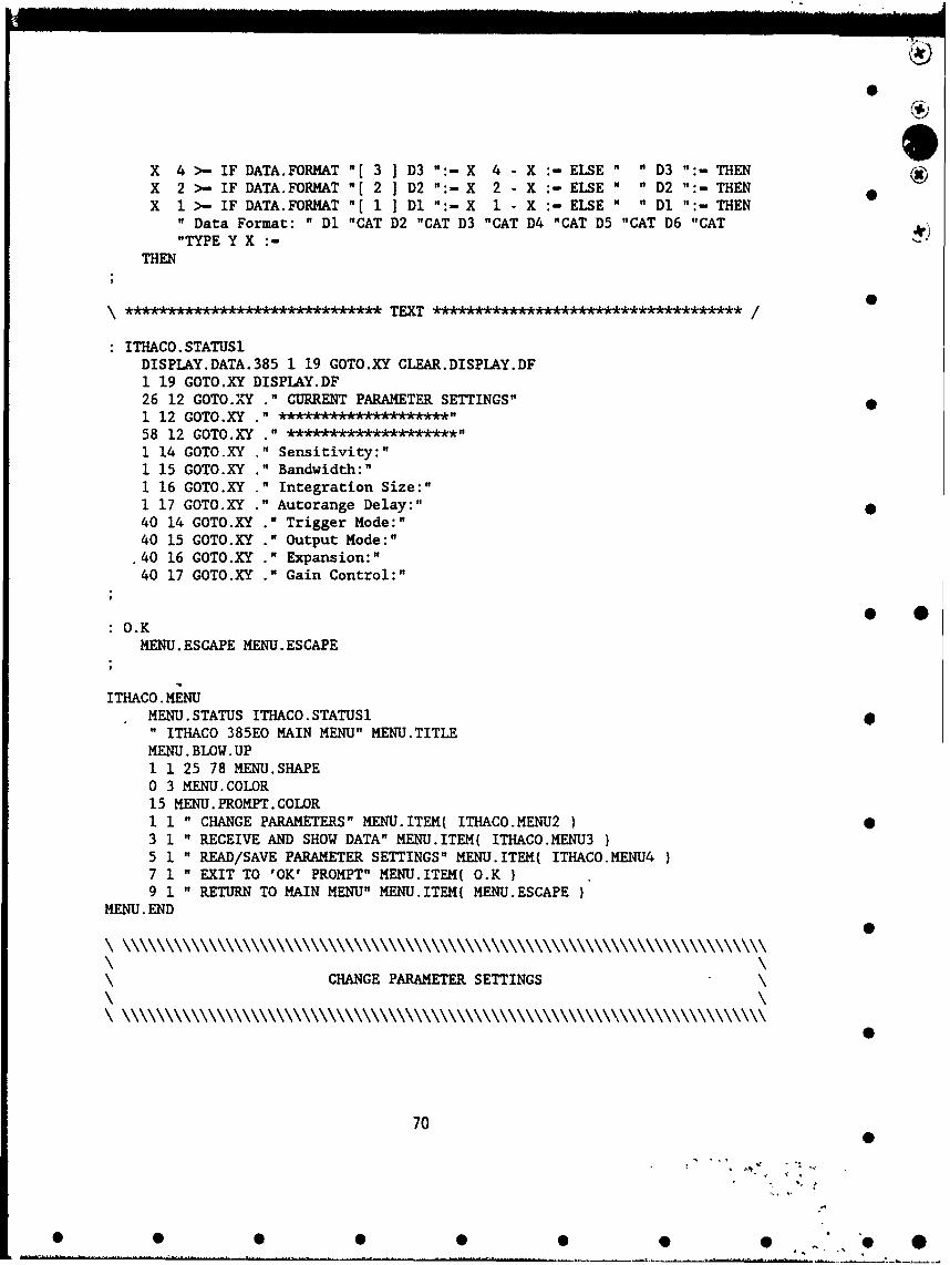
X 4 >- IF DATA.FORMAT "[ 3 ] D3 ":- X 4 - X :- ELSE " " D3 ":- THENX 2 >- IF DATA.FORMAT "[ 2 ] D2 ":- X 2 - X :- ELSE " " D2 ":- THENX 1 >- IF DATA.FORMAT "[ 1 Dl ":- X 1 - X :- ELSE " " Dl ":- THEN
" Data Format: " Dl "CAT D2 "CAT D3 "CAT D4 "CAT D5 "CAT D6 "CAT"TYPE Y X :-
THEN
\ * •� � � �-A TEXT ************** * * ********* /
ITHACO.STATUSIDISPLAY.DATA.385 1 19 GOTO.XY CLEAR.DISPIAY.DF1 19 GOTO.XY DISPLAY.DF26 12 GOTO.XY ." CURRENT PARAMETER SETTINGS"1 12 GOTO.XY ." . .... ***"58 12 GOTO.XY ." ********************"1 14 GOTO.XY ." Sensitivity:"1 15 GOTO.XY ." Bandwidth:"1 16 GOTO.XY ." Integration Size:"1 17 GOTO.XY ." Autorange Delay:"40 14 GOTO.XY ." Trigger Mode:"40 15 GOTO.XY ." Output Mode:"
.40 16 GOTO.XY ." Expansion:"40 17 GOTO.XY ." Gain Control:"
O.KMENU. ESCAPE MENU. ESCAPE
ITHACO. MENUMENU. STATUS ITHACO. STATUS1" ITHACO 385EO MAIN MENU" MENU.TITLEMENU. BLOW. UP1 1 25 78 MENU.SHAPE0 3 MENU.COLOR15 MENU. PROMPT. COLOR1 1 " CHANGE PARAMETERS" MENU.ITEM( ITHACO.MENU2 •3 1 " RECEIVE AND SHOW DATA" MENU.ITEM( ITHACO.MENU35 1 " READ/SAVE PARAMETER SETTINGS" MENU.ITEM{ ITHACO.MENU47 1 " EXIT TO 'OK' PROMPT" MENU.ITEM{ O.K9 1 " RETURN TO MAIN MENU" MENU.ITEM( MENU.ESCAPE
MENU. END
CHANGE PARAMETER SETTINGS
70
70.
• • •• • • • "O

ow
EDIT.PARAMETER.385 P 4 *3 - PCLR.DATA 12 BACKGROUND CLR.UNITS.DISPLAY7 4 DO I P + 3 - Z :- 40 I GOTO.XY UNITS.DISPLAY.385 "[Z ]"TYPE LOOPX.C Y.C GOTO.XY CLRSCR 1 DATA.L "SUB "TYPEK.C Y.C GOTO.XY "INPUT COM.DATA :ITH385 LISTENER ME TALKER 0 BACKGROUNDUNITS.DISPLAY.385 "[ P ] COM.DATA "CAT COM I':- COM. TCLR.DATA CLR.UNITS.DISPLAY;
FS \ CHANGE FULL SCALE SENSITIVITY20 X.C :- 18 COLUMN :- 1 P .-
14 Y.C 1- DATA.L : EDIT.PARAMETER.385;
BW \ CHANGE BANDWIDTH20 X.C := 18 COLUMN := 2 P :
15 Y.C I- DATA.L,: EDIT.PARAMETER.385
IL \ CHANGE INTEGRATION LENGTH20 X.C :- 18 COLUMN :- 3 P :-16 Y.C :- 4 DATA.L :- EDIT.PARAMETER.385
AD \ CHANGE AUTORANGE DELAY20 X.C :- 18 COLUMN :- 4 P :
17 Y.C :- 4 DATA.L EDIT.PARAMETER.385;* *TM CHANGE TRIGGER MODE
55 X.C :- 24 COLUMN :- 5 P :
14 Y.C :- 1 DATA.L :- EDIT.PARAMETER.385
OM \ CHANGE OUTPUT MODE55 X.C :~24 COLUMN 6 P :15 Y.C :- 1 DATA.L EDIT.PARAMETER.385
EX \ EXPANSION MODE55 X.C :- 24 COLUMN :- 7 P16 Y.C := 1 DATA.L :~EDIT.PARAMETER.385;
GC \ CHANGE GAIN CONTROL55 X.C :- 24 COLUMN := 8 P17 Y.C :- 1 DATA.L := EDIT.PARAMETER. 385
EDIT.DATA.FORMAT DF DATA.FORMAT "( D]IF X Z - X :- CLRSCR 1 10 "SUB DF ":-
ELSE X Z + X :-THEN "D" X """CAT COM.DATA "-COM.DATA GW
D1.385 SC 1 Z :-I D :-Dl DF "-EDIT.DATA.FORMAT DF Dl :
71
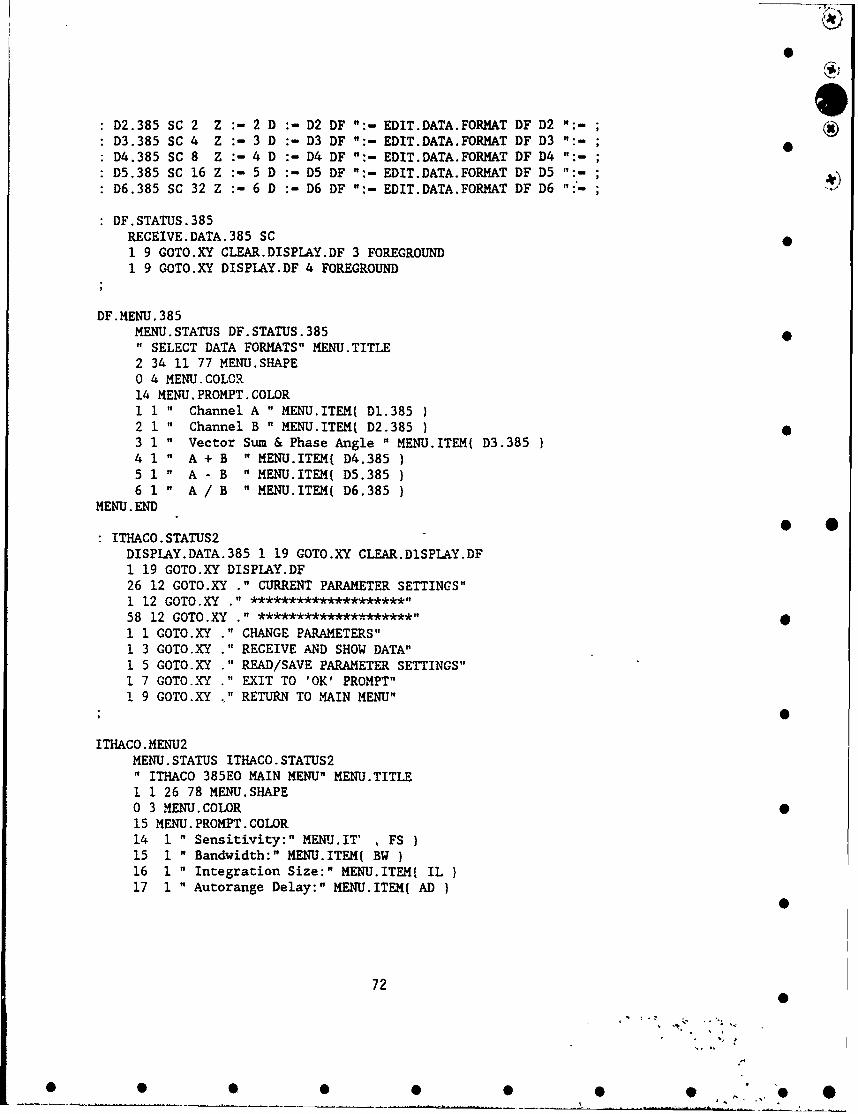
D2.385 SC 2 Z :- 2 D :- D2 DF ":- EDIT.DATA.FORMAT DF D2 ":-D3.385 SC 4 Z :- 3 D :- D3 DF ":- EDIT.DATA.FORMAT DF D3 ":- ;D4.385 SC 8 Z :- 4 D :- D4 DF ":- EDIT.DATA.FORMAT DF D4 ":-D5.385 SC 16 Z :- 5 D :- D5 DF ":- EDIT.DATA.FORMAT DF D5 ":- ,D6.385 SC 32 Z :- 6 D :- D6 DF ":- EDIT.DATA.FORMAT DF D6 ":-
DF.STATUS.385RECEIVE.DATA.385 SC1 9 GOTO.XY CLEAR.DISPLAY.DF 3 FOREGROUND1 9 GOTO.XY DISPLAY.DF 4 FOREGROUND
DF.MENU.385MENU. STATUS DF. STATUS.385 0" SELECT DATA FORMATS" MENU.TITLE2 34 11 77 MENU.SHAPE0 4 MENU.COLOR14 MENU.PROMPT.COLOR1 1 " Channel A " MENU.ITEM( D1.385 I2 1 " Channel B " MENU.ITEM( D2.385 )3 1 " Vector Sum & Phase Angle " MENU.ITEM( D3.385 }4 1 " A + B " MENU.ITEM( D4.385 )5 1 " A - B " MENU.ITEM( D5.385 )6 1 " A / B " MENU.ITEM( D6.385
MENU. END
ITHACO.STATUS2DISPLAY.DATA.385 1 19 GOTO.XY CLEAR.D1SPLAY.DF1 19 GOTO.XY DISPLAY.DF26 12 GOTO.XY ." CURRENT PARAMETER SETTINGS"1 12 GOTO.XY " ********************"58 12 GOTO.XY " *******************"1 1 COTO.XY ." CHANGE PARAMETERS"1 3 GOTO.XY ." RECEIVE AND SHOW DATA"1 5 GOTO.XY ." READ/SAVE PARAMETER SETTINGS"1 7 GOTO.XY ." EXIT TO 'OK' PROMPT"1 9 GOTO.XY .' RETURN TO MAIN MENU"
ITHACO.MENU2MENU. STATUS ITHACO. STATUS2" ITHACO 385EO MAIN MENU" MENU.TITLE1 1 26 78 MENU.SHAPE0 3 MENU.COLOR 015 MENU. PROMPT. COLOR14 1 " Sensitivity:" MENU.IT' , FS15 1 " Bandwidth:" MENU.ITEM( BW }16 1 " Integration Size:" MENU.ITEM( IL17 1 " Autorange Delay:" MENU.ITEM{ AD I
72
"s, *
* S • 0 5 0 0 5 •' " 0

0
19 1 " Data Format:" MENU.ITEM( DF.MENU.38514 40 " Trigger Mode:" MENU.ITEM( TM )15 40 " Output Mode:" MENU.ITEM( OM16 40 " Expansion:" MENU.ITEM( EX )17 40 " Gain Control:" MENU.ITEM( GC )
MENU. END
0\ ~GRAPH DATA FROM THE AMPLIFIER\
CHANGE.NT. 3851 21 GOTO.XY ." INPUT NUMBER OF TEST DATA ( I - 10 ): " "INPUT NTS ":-NTS 32 "NUMBER NT :- 1 NT + NT :-17 NT < IF ."TOO HIGH" 17 NT :- THEN2 NT > IF ."TOO LOW "2 NT :- THEN1 21 GOTO.XY CLRSCR "TYPE CLRSCR "TYPE 0
INIT.TEST.385CPS.385 8 2 "SUB 0 "NUMBER X :-
0 AOD :- X Y :-X 0 lF I
X 32 >- IF 13 AOD :- X 32 - X :l THENX 16 >- IF 10 AOD + AOD :X 16 X :-THENX 8 >- IF 10 AOD + AOD :X X 8 - X -- THENX 4 >- IF 17 AOD + AOD :- X 4 - X THENX 2 >- IF 10 AOD + AOD :- X 2 - X -- THENX 1 >- IF 10 AOD + AOD :- 1 1 - X :- THEN 0
T EN
CLEAR.TEST.DISPLAY.38522 2 DO1 I GOTO.XY CLRSCR "TYPE 037 1 GOTO.XY CLRSCR "TYPE72 1 GOTO.XY CLRSCR 1 4 "SUB "TYPE
LOOP
TEST.385 0
CLEAR.TEST.DISPLAY.235ITH385
" TI" GWNT 1 DO
RAW.DATA.385 "[ I ] GR
73 0
0 0 0 0 0 0 0 S

/
0
LOOPTE" GW 0
CONVERT. 3851 AOD + AOD
7 1 DO100 ST I]:-
LOOPY X :-XO <> IF
X 32 >- IF AOD 13 - AOD :- AOD ST [ 1 ] :- X 32 - X :- THENX 16 >- IF AOD 10 - AOD :- AOD ST 2 ] :- X 16 - X :- THENX 8 >- IF AOD 10 - AOD :-AOD ST 3] X 8 - X :-THEN 0X 4 >- IF AOD 17 - AOD :- AOD ST [ 4 ] :- X 4 - X :- THENX 2 >- IF AOD 10 - AOD :- AOD ST [ 5 ] :- X 2 - X :- THENX 1 >- IF AOD 10 - AOD :- AOD ST [ 6 1 :- X 1 - X :- THEN
THENNT I DO
100 ST [ 1 ] - IF " N A" A/B "f I ] ":- ELSERAW.DATA.385 "( I ] ST [ 1 ] 13 "SUB A/B "[ I ] ":- THEN100 ST [ 2 1 -IF " N A" A-B "[ I ] ":- ELSERAW.DATA.385 "[ I ] ST [ 2 1 10 "SUB A-B "[ I ] ":- THEN100 ST [ 3 1 - IF " N A" A+B "[ I ] ":- ELSERAW.DATA.385 "t I ] ST [ 3 ] 10 "SUB A+B "I I ":-THEN100 ST [ 4 ] - IF " N A" PHASE "[ I I ":- " N A" AB "[ I ] ":- • *ELSE RAW.DATA.395 "[ I ] ST [ 4 1 10 + 7 "SUB PHASE " I ":-
RAW.DATA.385 "[ I ] ST [ 4 1 10 'SUB AB "[ I ] ":-THEN100 ST [ 5 1 - IF " N A" B "[ I ] ":- ELSERAW.DATA.385 "[ I ] ST [ 5 ] 10 "SUB B "[ I ] ":-B "[ I ] 0 "NUMBER REAL BN [ I ] :-STACK.CLEAR THEN100 ST ( 6 ] - IF " N A" A "[ I ] ":- ELSE 0RAW.DATA.385 "[ I I ST [ 6 1 10 "SUB A "t I ] ":-A "[ I ] 0 "NUMBER REAL AN I I ] :- STACK.CLEAR THEN
LOOP
SHOW.DATA.385 5 YC :-NT I DO
1 YC GOTO.XY A "[ I ] "TYPE12 YC'GOTO.XY B "[ I ] "TYPE23 YC GOTO.XY AB "[ I ] "TYPE34 YC GOTO.XY PHASE "[ I ) "TYPE42 YC GOTO.XY A+B "[ I ] "TYPE53 YC GOTO.XY A-B "[ I ] "TYPE64 YC GOTO.XY A/B "t I -"TYPE1 YC + YC
LOOP
74
0
7,.
• • •• • • O ", "O

DISPLAY. TEST. RESULTS4 FOREGROUNDINIT.TEST. 385
TEST.385 4
CONVERT.3853 3 GOTO.XY ."CHAN A" 14 3 GOTO.XY ."CHAN B" 23 3 GOTO.XY ."VECTOR SUM"
35 3 GOTO.XY ."PHASE" 44 3 GOTO.XY ."A +~ B11 54 3 GOTO.XY ."A -B"0
68 3 GOTO.XY ."A/B"
1 FOREGROUNDSHOW.DATA. 3853 FOREGROUND
Execute Specific Parameter Changes
:SCS.385 \SAVE CURRENT SETTINGSSAVE. RESTORE. MENU MENU. EXECUTE IN
CPS.385 CPSI.385 ">ARRAY \ ASYST FORMAT
FILE.TEMPLATEINTEGER DIM[ 100 ] SUBFILE 0
ENDFILE. NAME DEFER> FILE. CREATEFILE. NAME DEFER> FILE. OPEN1 SUBFILE CPSI.385 ARRAY>FILEFILE.CLOSE MENU.ESCAPE;
:RSS.385 \RESTORE SAVED SETTINGS
SAVE.RESTORE.MENU MENU.EXECUTE IN
FILE.NAME DEFER> FILE.OPEN \ ASYST FORMAT
1 SUBFILE CPSI.385 FILE>ARRAYFILE. CLOSECPSI.385 CPS.385 ARRAY>"ITH385CPS.385 1 164 "SUB GW
255 SPD 5CUT:MENU.ESCAPE;
ITHACO .MENU42 50 6 76 MENU.SHAPE3 0 MENU.COLOR14 MENU. PROMPT. COLOR1 2 "GO TO THE O.K. PROMPT" MENU.ITEM( OKP
0
75 0
0 0 0 0 0 0 07.

0
2 2 " SAVE CURRENT SETTINGS" MENU.ITEM( SCS.3853 2 " READ SAVED SETTINGS" MENU.ITEM{ RSS.385
MENU. END
0
0
76
Mt , 0
• • • • •• • • ,, * 0, O•
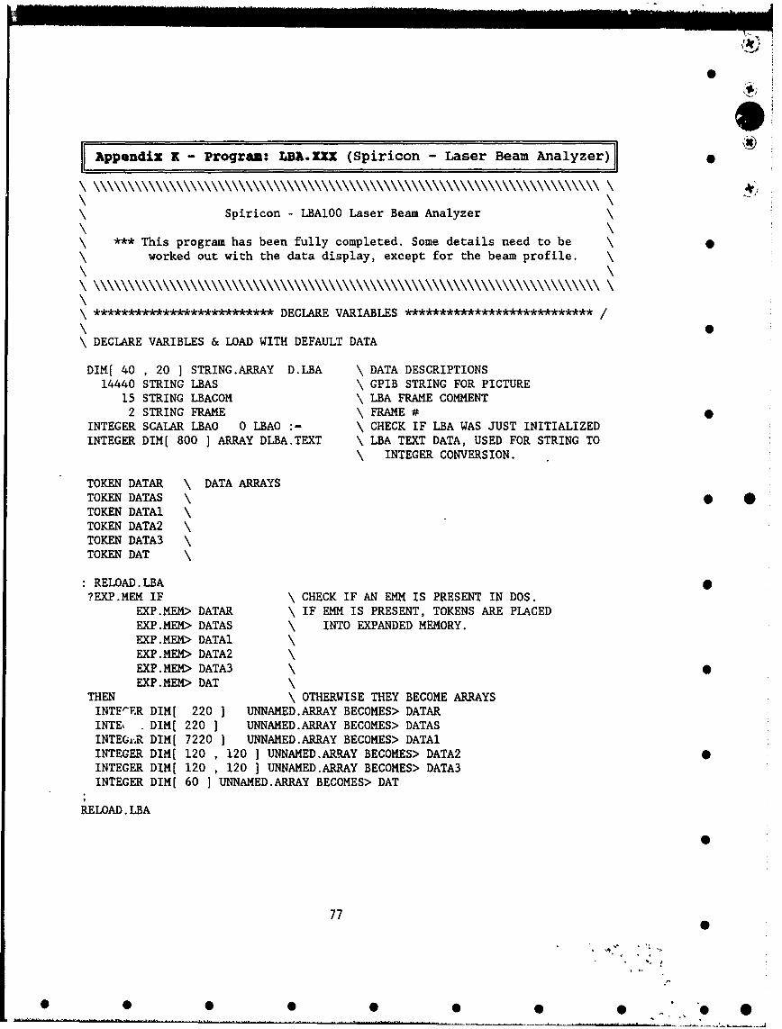
AJ ppendix K- Program: LBA.XhI (Spiricon -Laser Beam Analyzer)
Spiricon - LBA100 Laser Beam Analyzer
*** This program has been fully completed. Some details need to beworked out with the data display, except for the beam profile.
************************** DECLARE VARIABLES ************************ /
\ DECLARE VARIBLES & LOAD WITH DEFAULT DATA
DIM[ 40 , 20 ] STRING.ARRAY D.LBA \ DATA DESCRIPTIONS14440 STRING LBAS \ GPIB STRING FOR PICTURE
15 STRING LBACOM \ LBA FRAME COMMENT2 STRING FRAME \ FRAME #
INTEGER SCALAR LBAO 0 LBAO :- \ CHECK IF LBA WAS JUST INITIALIZEDINTEGER DIM[ 800 ] ARRAY DLBA.TEXT \ LBA TEXT DATA, USED FOR STRING TO
\ INTEGER CONVERSION.
TOKEN DATAR \ DATA ARRAYSTOKEN DATAS \ • OTOKEN DATA1 \TOKEN DATA2 \TOKEN DATA3 \TOKEN DAT
RELOAD. LBA?EXP.MEM IF \ CHECK IF AN EMM IS PRESENT IN DOS.
EXP.MEM> DATAR \ IF EMM IS PRESENT, TOKENS ARE PLACEDEXP.MEM> DATAS \ INTO EXPANDED MEMORY.EXP.MEM> DATAlEXP. MEM> DATA2EXP. MEM> DATA3EXP. MEM> DAT
THEN \ OTHERWISE THEY BECOME ARRAYSINTFE-R DIM[ 220 ] UNNAMED.ARRAY BECOMES> DATARINTE . DIM[ 220 ] UNNAMED.ARRAY BECOMES> DATASINTEG,..R DIM[ 7220 ] UNNAMED.ARRAY BECOMES> DATAMINTEGER DIM[ 120 , 120 ] UNNAMED.ARRAY BECOMES> DATA2 0INTEGER DIM[ 120 , 120 ] UNNAMED.ARRAY BECOMES> DATA3INTEGER DIM[ 60 ] UNNAMED.ARRAY BECOMES> DAT
RELOAD. LBA
77
% 1
* 0 0 0 0 0 0 0 * 0

*
MENU LBA.MENU \ DECLARE MENUSMENU SRLBA \VUPORT LBA.PORT \ DECLARE VUPORT IN GRAPHICS DISPLAY
0 .252 VUPORT.ORIG \ ORIGIN1 .748 VUPORT.SIZE \ SIZE
20 0 25 80 WINDOW LBA.WIN \ DECLARE GRAPHICS WINDOW
************************** COLON DEFINITIONS *********************** /
LBAONE \ IF IT IS FIRST COMMUNICATION, YOU HAVE TO SEND " :REM"0 LBAO - IF LBA-100 " :REM" GW COM GRTHEN 2 LBAO :- ;
RLBAF \ READ A FRAME OF DATA FROM THE LBA" :CAP 1 " "CR.LF" "CAT GW
" :KRS " "CR.LF" "CAT GW":STS? " "CR.LF" "CAT GW
LBAS GRLBAS 44 "NUMBER SS.CLEAR "." FRAME ":-40 20 GOTO.XY ." .... READING FRAME # " FRAME "TYPE" :RDD? " FRAME "CAT "CR.LF" "CAT COM ":- COM GWLBAS GR LBAS 14 14393 "SUB DATAl ">ARRAY" :FST? " FRAME "CAT "CR.LF" "CAT COM ":- COM GWLBAS GR LBAS 5 240 "SUB DATAS ">ARRAY * *" :RDR? " FRAME "CAT "CR.LF" "CAT COM ":- COM GWLBAS GR LBAS 7 200 "SUB DATAR ">ARRAY
GLBAF \ GRAPH LBA PICTURE16 GRAPHICS.DISPLAY.MODE \ GRAPHICS MODEGRAPHICS.DISPIAY \ GO TO GRAPHICS DISPLAYLBA.WIN \ USE GRAPHICS WINDOWLBA.PORT \ USE GRAPHICS VUPORTVUPORT. CLEAR \ CLEAR VUPORTOUTLINE \ OUTLINE THE VUPORT 0(BORDER) \ OUTLINE THE WINDOW
121 1 DO \ REPLOT PICTURE PIXEL BY PIXEL121 1 DO
DATA2 [ J , I ] COLOR1 2 *396 + M -M 1 + Y :- 0J 2 L :-348 L - N :- N 1 - Z :-
M N P! M Z P!Y N P! Y Z P!
LOOP0
78 0
* 0 0 0 0 0 0 0 0 0

LOOP
3 COLOR \ LABEL DATA
.05 .96 POSITION " Total " LABEL
.05 .92 POSITION " Peak " LABEL
.05 .88 POSITION " Peak Loc " LABEL
.05 .84 POSITION " Centroid " LABEL
.05 .80 POSITION " Diameter " LABEL
.05 .72 POSITION " Elliptical Beam LABEL
.05 .68 POSITION Major Axis " LABEL
.05 .64 POSITION " Minor Axis " LABEL
.05 .60 POSITION " Orientation " LABEL
.05 .56 POSITION It Roundness " LABEL
.05 .50 POSITION Gauss fit " LABEL
.05 .44 POSITION " CTR, Width " LABEL
.05 .41 POSITION " Height " LABEL
.05 .38 POSITION " Correlation " LABEL
.05 .33 POSITION " ctr, width " LABEL
.05 .30 POSITION " height " LABEL
.05 .27 POSITION " correlation " LABEL
.35 .96 POSITION " Top Hat " LABEL
.35 .92 POSITION " Mean " LABEL
.35 .88 POSITION Dev " LABEL
.35 .84 POSITION " Min " LABEL
.35 .80 POSITION Max " LABEL * *
.35 .72 POSITION " LABEL
.35 .68 POSITION " Divergeance LABEL
.35 .64 POSITION " I - " LABEL
.35 .60 POSITION " Elliptical L LABEL
.35 .56 POSITION " ELLIPSE " LABEL.35 .50 POSITION " SPIRICON " LABEL.35 .44 POSITION " 1y BKD " LABEL.35 .41 POSITION " " LABEL.35 .38 POSITION "" LABEL.35 .33 POSITION " " LABEL
CURSOR.OFF
LBA.WIN2 2 GOTO.XY ." ENTER PCX FILENAME: "
"INPUT FILE.NAME ":-
500 MSEC.DELAY22 GOTO.XY ." ... NOW SAVING PCX IMAGE TO FILE IFILE.NAME DEFER> VUP>PCX"INPUT SS.CLEARMENU.ESCAPE
79
-* r S
* 0 • 0 0 0 0 ~ "J "O *
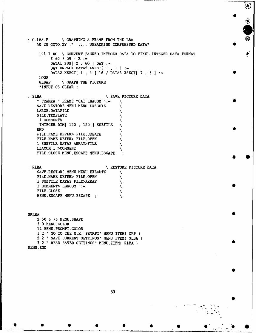
G.LBA.F \ GRAPHING A FRAME FROM THE LBA40 20 GOTO.XY ." ... UNPACKING COMPRESSED DATA"
121 1 DO \ CONVERT PACKED INTEGER DATA TO PIXEL INTEGER DATA FORMAT1 60 *59 - X :-DATAl SUB[ X , 60 1 DATDAT UNPACK DATA2 XSECT[ I , I ] :-DATA2 XSECT[ I,!] 16/ DATA3 XSECT( I,!]:- 0
LOOPGLBAF \ GRAPH THE PICTURE"INPUT SS.CLEAR ;
SLBA \ SAVE PICTURE DATA" FRAME# " FRAME "CAT LBACOM ":- \SAVE.RESTORE.MENU MENU.EXECUTELARGE.DATAFILEFILE.TEMPLATE
1 COMMENTSINTEGER DIM[ 120 , 120 ] SUBFILE \
END \FILE. NAME DEFER> FILE. CREATEFILE.NAME DEFER> FILE.OPEN1 SUBFILE DATA2 ARRAY>FILELBACOM 1 >COMMENTFILE.CLOSE MENU.ESCAPE MENU.ESCAPE
RLBA \ RESTORE PICTURE DATASAVE.RESTJRrL.MENU MENU.EXECUTEFILE.NAME DEFER> FILE.OPEN1 SUBFILE DATA2 FILE>ARRAY1 COMMENT> LBACOM ":-FILE.CLOSEMENU.ESCAPE MENU.ESCAPE ;
SRLBA 02 50 6 76 MENU.SHAPE3 0 MENU.COLOR14 MENU.PROMPT.COLOR1 2 " GO TO THE O.K. PROMPT" MENU.ITEM( OKP2 2 " SAVE CURRENT SETTINGS" MENU.ITEM{ SLBA3 2 " READ SAVED SETTINGS" M2NU.ITEM( RLBA
MENU. END
80
80L
O • • •• •O" ' "O
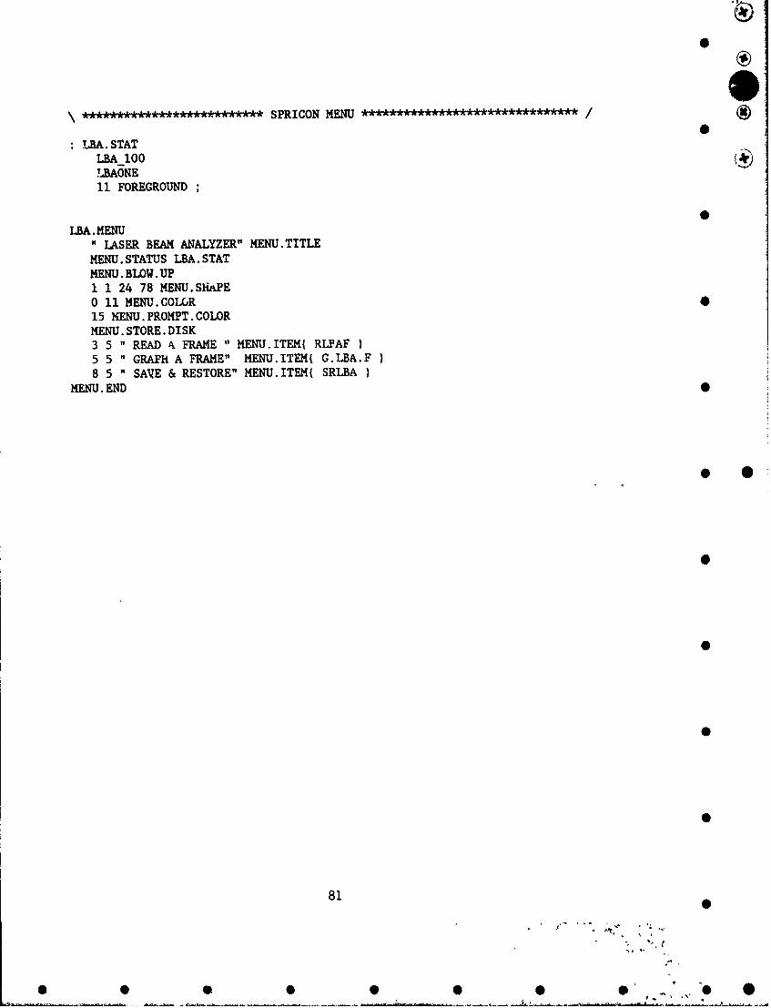
~A~kA*~***A~kA*AAAASPRICON MENU****************/
LBA.STATLBA_100 )TLBAO0NE11 FOREGROUND
LBA. MENU" LASER BEAM ANALYZER" MENU.TITLE
MENU. STATUS LBA. STATMENU. BLOW. UP1 1 24 78 MENU.SkiaPEOi11 MENU. COLCR15 MENU. PROMPT. COLORMENU. STORE .DISK3 5 " READ k~ FRAME " MENU.ITEM{ RLPAF5 5 " GRAPH A FRAME" MENU.ITEMI G.LBA.F8 5 " SAVE & RESTORE" MENU.ITEM( SRLBA
MENU. END
81

B Appendiz L - Program: JOR.Xxx (Non-Linear Optical Switch Test) *
Non-Linear Optical Switch Test Control Program (NLOSTCP)
\ ******************....... DECLARE VARIABLES * * * *********** /
\ DECLARE VARIBLES & LOAD WITH DEFAULT DATA
5 STRING INT \ Number of Intervals20 STRING D.W \ Read W axis Display 0
8 STRING KMD.S \ Klinger Motor String30 STRING FNAME " D:\NLINTSW" FNAME ": \ Default File Name
INTEGER SCALAR CDETEC 2 CDETEC :- \ Change DetectorINTEGER SCALAR KMD.hINTEGER SCALAR OPTIONJ \ Joe's Options
DP.INTEGER SCALAR VDP.INTEGER SCALAR U
REAL SCALAR STRING.NUM \ Convert String to NumberDP.&EAL SCALAR DEGREE \ Substrate Angle of Reflection
DP.REAL DIM( 1000 , 2 ] ARRAY DATA123 0 DATA]23 -
" NO" INT.PAUSE ":-
TOKEN TOTAL TOKEN XCOORTOKEN DEGREES TOKEN YCOORTOKEN PEAK TOKEN ZCOORTOKEN DATA. 123
RELOAD.JOE?EXP.MEM IF
EXP.MEM> TOTAL EXP.MEM> XCOOREXP.MEM> DEGREES EXP.MEM> YCOOREXP. MEM> PEAK EXP. MEM> ZCOOREXP.MEM> DATA.123
THEN1000 DP.REAL RAMP BECOMES> TOTAL1000 DP.REAL RAMP BECOLES> DLJREES1000 DP.REAL RAMP BECOMES> PEAK0 TOTAL :- 0 DEGREES :- 0 PEAK -
RELOAD. JOE
82
° S
• • •• • • o " o
* 0 0 0,0 5-
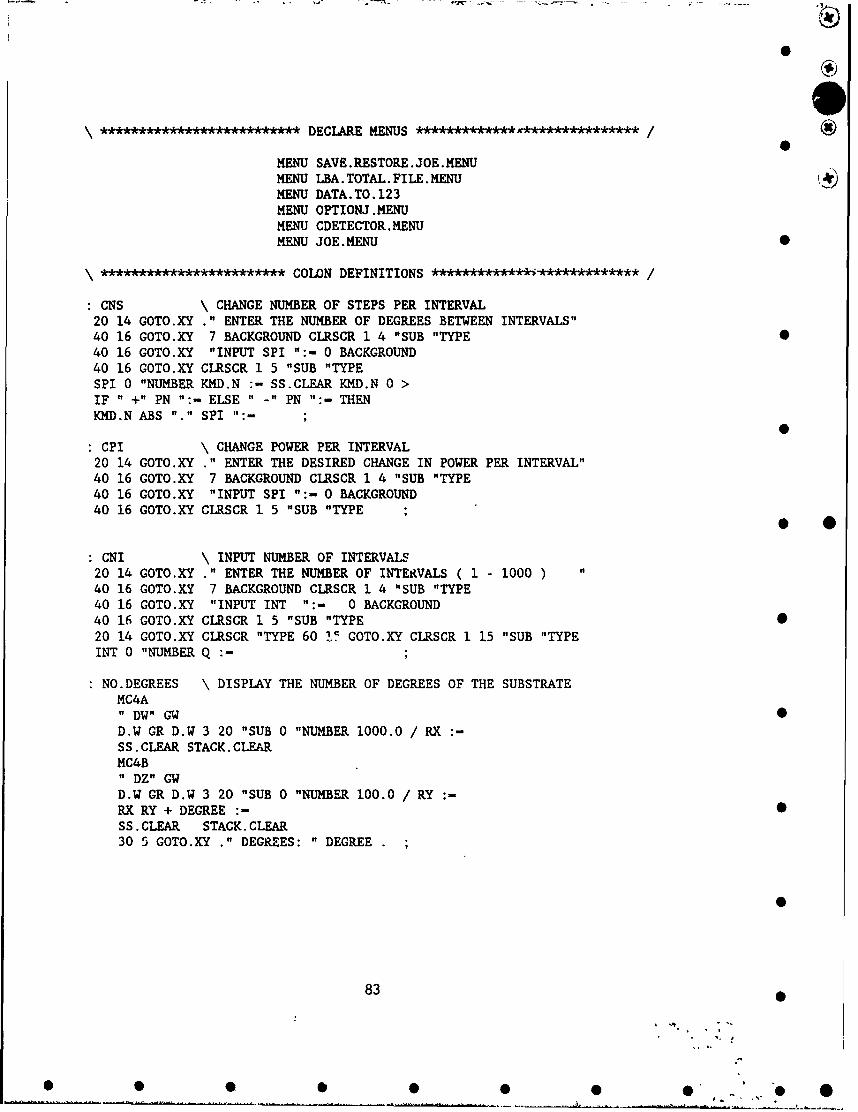
0 ie
\ *� ��� DECLARE MENUS *** /S
MENU SAVE.RESTORE.JOE.MENUMENU LBA. TOTAL.FILE.MENUMENU DATA.TO.123MENU OPTIONJ.MENUMENU CDETECTOR. MENUMENU JOE.MENU 0
************************ COLON DEFINITIONS ************************* /
CNS \ CHANGE NUMBER OF STEPS PER INTERVAL20 14 GOTO.XY ." ENTER THE NUMBER OF DEGREES BETWEEN INTERVALS"40 16 GOTO.XY 7 BACKGROUND CLRSCR 1 4 "SUB "TYPE40 16 GOTO.XY "INPUT SPI ":- 0 BACKGROUND40 16 GOTO.XY CLRSCR 1 5 "SUB "TYPESPI 0 "NUMBER KMD.N -- SS.CLEAR KMD.N 0 >IF " +" PN "'- ELSE -" PN ":- THENKMD.N ABS "." SPI "'-
CPI \ CHANGE POWER PER INTERVAL20 14 GOTO.XY ." ENTER THE DESIRED CHANGE IN POWER PER INTERVAL"40 16 GOTO.XY 7 BACKGROUND CLRSCR 1 4 "SUB "TYPE40 16 GOTO.XY "INPUT SPI ":- 0 BACKGROUND40 16 GOTO.XY CLRSCR 1 5 "SUB "TYPE
CNI \ INPUT NUMBER OF INTERVALS20 14 GOTO.XY " ENTER THE NUMBER OF INTERVALS ( 1 - 1000 ) "
40 16 GOTO.XY 7 BACKGROUND CLRSCR 1 4 "SUB "TYPE40 16 GOTO.XY "INPUT INT ":- 0 BACKGROUND40 16 GOTO.XY CLRSCR 1 5 "SUB "TYPE20 14 GOTO.XY CLRSCR "TYPE 60 17- GOTO.XY CLRSCR 1 15 "SUB "TYPEINT 0 "NUMBER Q :-
NO.DEGREES \ DISPLAY THE NUMBER OF DEGREES OF THE SUBSTRATEMC4A" DW" GW 0D.W GR D.W 3 20 "SUB 0 "NUMBER 1000.0 / RX :-SS.CLEAR STACK.CLEARMC4B" DZ" GWD.W GR D.W 3 20 "SUB 0 "NUMBER 100.0 / RY :-RX RY + DEGREE :- 0SS. CLEAR STACK. CLEAR30 5 GOTO.XY ." DEGREES: " DEGREE
83
• • • • • • • ' O

: IID 1 OPTIONJ - MENU.ESCAPE ; \ OPTION - CHANGE REFLECTION ANGLE: ILP 2 OPTIONJ -MENU.ESCAPE ; \ OPTION - CHANGE LASER POWER: IIDAZ 3 OPTIONJ :- MENU.ESCAPE ; \ OPTION - CHANGE ANGLE THEN HEIGHT
OPTIONJ.MENU \ OPTIONS MENU2 50 4 76 MENU.SHAPEMENU. NO. BORDER3 0 MENU.COLOR14 MENU. PROMPT.COLOR0 2 " INCREMENT IN DEGREES" MENU.ITEM( IID1 2 " INCREMENT LASER POWER" MENU.ITEM( ILP2 2 " DEGREES & Z AXIS" MENU.ITEM( IIDAZ }
MENU. END
JO ************** MAIN PROGRAM ************************** / •
OPTIONJ.MENU MENU.EXECUTE \ FIRST, ASK FOR OPTIONS1 X :- 12 FOREGROUND1 CDETEC - IF I BACKGROUND \ IF YOU ARE USING THE LBA, EACH PICTURE
\ MUST BE STORED IMMEDIATELY DUE TO\ MEMORY CONSTRAINTS.
25 16 GOTO.XY ." LEAVE OFF FILE EXTENSION "20 17 GOTO.XY ." FILENAME MUST BE LESS THAN 6 LETTERS "
SAVE.RESTORE.MENU MENU.EXECUTE FILE.PATH " \V" "CAT NAME.FILE "CATFNAME ":- 0 BACKGROUND25 16 GOTO.XY CLRSCR "TYPE * •20 17 GOTO.XY CLRSCR "TYPE 50 17 GOTO.XY CLRSCR LO "SUB "TYPE
THENOPTIONJ CASE \ ASK FOR PARAMETERS FOR CHOSEN
1 OF CNS CNI ENDOF \ TEST OPTION.2 OF CPI CNI ENDOF3 OF CNS CNI
40 13 GOTO.XY ." ENTER NUMBER OF Z AXIS MOVES"7 BACKGROUND 50 14 GOTO.XY CLRSCR 1 5 "SUB "TYPE50 14 GOTO.XY "INPUT SS ":- SS 0 "NUMBER X :- SS.CLEARX I < IF 1 X :- THEN 0 BACKGROUND40 13 GOTO.XY ." ENTER Z AXIS STEPS PER MOVE7 BACKGROUND 50 14 GOTO.XY CLRSCR 1 5 "SUB "TYPE50 14 GOTO.XY "INPUT SS ":-" NZ" SS "CAT CON ":- COM GW20 FOREGROUND.2 BACKGROUND1 CDETEC <> IF \ LBA MUST SAVE AFTER EACH MOVE20 6 GOTO.XY ." LEAVE OFF FILE EXTENSION " 0 BACKGROUND2 SAVE.RESTORE.MENU MENU.EXECUTE FILE.PATH " \" "CAT NAME.FILE "CATFNAME ":- MENU.ESCAPE THEN ENDOF
ENDCASE
11 FOREGROUNDSPI 0 "NUMBER KMD.N :- SS.CLEAR
84
"".
0 0 0 0 0 0 0 ** "7-

0
2 OPTIONJ 0 IF \ SET THE DIRECTION AND NUMBERMC4A \ OF STEPS FOR THE KLINGER MOTORSPN " +" IF " -W" COM ":- ELSE " +W" CON ":- THEN COM GWKMD.N 1000.0 * Z :- Z "." SS ":-" NW" SS "CAT COM ":- COM GWMC4BPN " Z" "CAT SS ":- 5S GWKMD.N 200.0 * Z :- Z "." SS ":-" NZ " SS "CAT SS ":- SS GWQ 1 + Q :- 12 FOREGROUND
THEN
X 1 DO ***** START PROGRAM LOOPS ******** /QIDO
INT.PAUSE " YES" "-
IF 20 28 GOTO.XY PAK "TYPE PCKEYELSE 2000 MSEC.DELAY THEN
1 CDETEC - IFLBA_100 \ USING SPIRICON LASER BEAM ANALYZERLBAONE \ BECAUSE OF THE SIZE IT MUST BE SAVEDRLBAF \ IMMEDIATELY FOLLOWING BEING RECEIVEDLBAS 12 20 "SUB 44 "NUMBER TOTAL [ I ] :-?DROP 44 "NUMBER PEAK [ I ] :-
FNAME J "." 2 "LEN 2 - "SUB "CAT FILE.NAME ":- * *FILE.NAME " ." ",CAT-I "." 2 "LEN 2 - "SUB "CAT FILE.NAME ":-LARGE. DATAFILEFILE. TEMPLATE
INTEGER DIM[ 7220 1 SUBFILEINTEGER DIM[ 220 ] SUBFILEINTEGER DIM[ 220 ] SUBFILE
ENDFILE. NAME DEFER> FILE. CREATEFILE.NAME DEFER> FILE.OPEN
1 SUBFILE DATAl ARRAY>FILE2 SUBFILE DATAR ARRAY>FILE3 SUBFILE DATAS ARRAY>FILE S
FILE.CLOSE5 21 GOTO.XY ." .... SAVING TO " FILE.NAME "TYPE
ELSENWPM835 \ USING POWER METER FOR BEAM DETECTIONRESULTS.100 GRRESULTS.100 4 20 "SUB 44 "NUMBER TOTAL [ I ]
THEN
SS.CLEAR 14 FOREGROUNDNO.DEGREES \ REDISPLAY THE SUBSTRATE ANGLEDEGREE DEGREES [ I ] :-
85
L.-S0 0 0 7 . ...

30 15 GOTO.XY ." TOTAL POWER: " TOTAL [ I 1 1000 * ." mW
OPTIONJ 2 - IF \ LPC POWER IS RAMPEDLPC"P ? " "CR.LF" "CAT GWCOM GR COM 32 "NUMBER STRING.NUM :- SS.CLEARSTRING.NUM KMD.N + STRING.NUM :-STRING.NUM "." COM ":-" W" UNITS ":-
" P "COM "CAT UNITS "CAT COM COM GW-ELSE \ OTHERWISE THE KLINGER MOTORS MOVE
MC4B " MZ" GWMC4A " MW" GW " BW" SS "CAT COM ":- COM GW
THENSS.CLEAR 65 9 GOTO.XY ." INCREMENT #" V12 FOREGROUND 65 10 GOTO.XY I ." OF " Q
LOOP
3 OPTIONJ - IF \ AUTOMATICALLY SAVE DATA AFTER EACHJ "." SS ":- \ CHANGE IN THE Z AXISFNAME " ." "CAT SS "CAT FILE.NAME ":-LARGE. DATAFILEFILE. TEMPLATE
1 COMMENTSDP.REAL DIM[ 1000 ] SUBFILEDP.REAL DIM[ 1000 ] SUBFILEDP.REAL DIM[-1 ] SUBFILE1 CDETEC - IF DP.REAL DIM( 1000 ] SUBFILE THEN
ENDFILE. NAME DEFER> FILE. CREATEFILE. NAME DEFER> FILE. OPEN
1 SUBFILE TOTAL ARRAY>FILE2 SUBFILE DEGREES ARRAY>FILE3 SUBFILE C.FACTOR ARRAY>FILEC.FACTOR.UNIT 1 >COMMENT
FILE.CLOSEMC4A " MZ" GW
THENQ 1- Q
LOOP2000 440 TUNE1000 220 TUNE2000 880 TUNE11 FOREGROUND ;
. o AAA..A ....... A.tA END OF LOOP PROGRAM: JOE ....E.OO G O... /
MOVE.SETUP \ THIS ROUTINE CALCULATES THE CURRENT SUBSTRATE ANGLEMC4, " DW" GW \ FROM THE COUNTERS OF THE TWO ROTATIONAL STAGES,
86
S
0 0 • S 0 0 0 O" " "O

D.W GR D.W 3 20 "SUB 0 "NUMBER V :- SS.CLEAR \ THEN CALCULATES THEMC4B " DZ" GW \ NEEDED POSITIONS FOR AD.W GR D.W 3 20 "SUB 0 "NUMBER X - SS.CLEAR \ DESIRED ANGLE.X 5 * V + 1000/ RX :- \ ax- CURRENT ANGLE
\ MC4B "Z" IS THE DETECTOR AND MUST BE POSITIONED AT\ AN ANGLE TWICE THE SIZE OF MC4A "W" ( THE SUBSTRATE).\ THE MC4B "Z" AXIS STAGE IS 100 COUNTS PER DEGREE\ THE MC4A "W" AXIS STAGE IS 1000 COUNTS PER DEGREE\ THEREFORE THE COUNT DIFFERENCE IS 1/5.
13 FOREGROUND25 21 GOTO.XY ." INPUT THE NUMBER OF DEGREES FOR THE SETUP"11 FOREGROUND 7 BACKGROUND50 5 GOTO.XY CLRSCR 1 10 "SUB "TYPE50 5 GOTO.XY "INPUT SS ":- SS 0 "NUMBER KMD.N :- SS.CLEARMC4A \ CALCULATE FROM PREVIOUS POSITION THE NEW POSITIONRX 2 * KMD.N - 1000 * V :- V "." SS ":- " PW" SS "CAT SS ":- SS GWMC4B KMD.N RX < IF RX KMD.N :- THENKMD.N RX - 200 * U :- U "." SS ":- " PZ" SS "CAT SS ":- SS GWSTACK. CLEAR SS. CLEAR13 FOREGROUND 0 BACKGROUND25 21 GOTO.XY ." WAIT FOR THIS MESSAGE TO DISSAPEAR11 FOREGROUND
GTOTAL \ GRAPH THE DATA PREVIOUSLY TAKENGRAPHICS. DISPLAY * ODEGREES SUB[ 1 , Q I BECOMES> XCOORTOTAL SUB[ 1 , Q ] BECOMES> YCOORPEAK SUB[ 1 , Q ] BECOMES> ZCOORXCOOR YCOORXY.AUTO. PLOT1 CDETEC - IF ZCOOR Y.DATA.PLOT THEN 0"INPUT SS.CLEAR
STOP.AE.INT \ CHOOSE WHETHER TO STOP BETWEEN TAKING DATAINT.PAUSE " YES" "- IF " NO " INT.PAUSE ":-ELSE " YES" INT.PAUSE ":- THEN ;
87• w •0
S 5 • 5 0 0 0 O" " " O

AA~AAA*A*SAVE & RESTORE IN ASYST FORMAT
SLBA. TOTAL \SAVE CURRENT SETTINGSSAVE.RESTORE.MENU M ENU.EXECUTE INFILE.PATH - \" "CATNAME.FILE "CAT FILE.NAME :
LARGE.DATAFILE \ ASYST FORMATFILE.TEMPLATE
I COMMENTSDP.REAL DIM[ 10003 SUBFILEDtr.REAL DIM[ 1000 ]SUBFILEDP.REAL DIM[ 1 ] SUBFILE1 CDETEC - IFDP.REAL DIM[ 1000 ] SUBFILE THEN \
END)FILE.NAME DEFER> FILE.CREATEFILE.NAME DEFER> FILE.OPEN1 SUBFILE TOTAL ARRAY>FILE2 SUBFILE DEGREES ARRAY>FILE3 SUBFILE C.FACTOR ARRAY>FILE1 ODETEC - IF
4 SUBFILE PEAK ARRAY>FILE THEN\C.FACTOR.UNIT 1 >COMMENTFILE.CLOSE MENU.ESCAPE MENU.ESCAPE
RLBA. TOTAL \RESTORE SAVED SETTINGS* *SAVE.RESTORE.MENU MENU.EXECUTEFILE.PATH - \- -CAT IN ASYST FORMATNAME.FILE "CAT FILE.NAME ":-FILE.NAME DEFER> FILE.OPEN1 SUBFILE TOTAL FILE>ARRAY2 SUBFILE DEGREES FILE>ARRAY3 SUBFILE C.FACTOR FILE>ARRAY1 CDETEC - IF
4 SUBFILE PEAK FILE>ARRAY THEN\1 COMMENT> C.FACTOR.UNIT :
FILE.CLOSEMENU.ESCAPE MENU.ESCAPE ;
LBA. TOTAL. FILE. MENU2 50 6 76 MENU.SHAPE3 0 MENU.COLOR14 MENU. PROMPT. COLOR1 2 " GO TO THE O.K. PROMPT" MENU.ITEM( OKP )2 2 " SAVE CURRENT SETTINGS" MENU.ITEM{ SLBA.TOTAL3 2 " READ SAVED SETTINGS" MENU.ITEM( RLBA.TOTAL
MENU. END
0
880
0~ 0

AAAAAAA.AASAVE & RESTORE IN LOTUS 1-2-3 FORMAT
S123TOTAL DATA123 XSECT[ !,1 ] :
DEGREES DATA123 XSECT[ !,2 ] :
DATA123 SUB[ 1 , Q ; 1 , 2 ]EQUIV> DATA.123SAVE. RESTORE. MENU MENU. EXECUTEFILE.PATH - \- -CATNAME.FILE "CAT FILE.NAMI :
FILE. NAME DEFER> 123n ILE. CREATEFILE.NAME DEFER> 123FILE.OPEN1 1 123WRITE.ACROSS1 1 Q 2 123READ.RANGEDATA.123 ARRAY>123FILE123FILE.CLOSE MENU.ESCAPE MENU.ESCAPE\
R123 \RESTORE SAVED SETTINGSSAVE.RESTORE.MENU MENU.EXEGUTE \FILE.PATH - \- -CAT \ IN LOTUS 1-2-3NAME.FILE "CAT FILE.NAME ":-\FILE.NAME DEFER> 123FI LE.OPEN\WKS.INFO (4 ,IIQ :-DATA123 SUB[ 1 , Q ; 1 , 2 ] EQUIV> DATA.1231 1 Q 2 123READ.RANGE* *DATA.123 123FILE>ARRAY123FILE. CLOSEQ I. + Z :
Z 1 DODATA123 [1 1 ]TOTAL [ IDATA123 1 2 1DEGREES [ I I:
0
89
0 0 0 000 7 0 *

C123 \CONVERT DATA SAVED IN ASYST FORMAT TO LOTUS FORMATCLRSCR FILE.NAME :- \ AND PLACE ON DISK IN DRIVE A:SAVE. RESTORE. MENU MENU. EXECUTEFILE.PATH " ""CATNAME.FILE "CAT FILE.NAME":FILE.NAME SS ":- FILE.NAME " .DAT" "CAT FILE.NAME :
FILE.NAME DEFER> FILE.OPEN1 SUBFILE TOTAL FILE>ARRAY2 SUBFILE DEGREES FILE>ARRAY3 SUBFI"E C.FACTOR FILE>ARRAY1 COMMENT> C.FACTOR.UNIT ":-FILE.CLOSE SS FILE.NAME ":-" AA\- FILE.NAME "CAT " WKI" "CAT FILE.NAME":Q 1 + Q :- Q 1 DOTOTAL,[I ] DATA123 I ,1]DEGREES (I] DATA123 1I 2]:LOOP Q 1 - Q :-DATA123 SUB[ 1 , Q ; 1 ,2 ]BECOMES> DATA.123FILE.NAME DEFER> 123FILE.CREATEFILE.NAI4E DEFER> 123FILE.OPEN1 1 123WRITE.ACROSSDATA. 123 ARRAY>123FILE123FILE.CLOSE SS FILE.NAME ":- MENU.ESCAPE MENU.ESCAPE
DATA. TO.1232 50 7 76 MENU.SHAPE* *3 0 MENU.COLOR14 MENU. PROMPT. COLOR1 2 n GO TO THE O.K. PROMPT" MENU.ITEM{ 0KB2 2 n SAVE CURRENT SETTINGS" MENU.ITEM4( S1233 2 " READ SAVED SETTINGS" MENU.ITEMI R123 )4 2 " CONVERT FROM C: TO A:" MENU.ITEM{ C123
MENU. END
SAVE .RESTORE.JOE.MENUMENU. NO .BORDERMENU .BLOW .UP19 50 21 68 MENU.SHAPE3 0 MENU.COLOR14 MENU.PROMPT.COLORMENU. STORE.DISK1 5 "LOTUS 1-2-3" MENU.ITEM( DATA.TO.1231 21 "ASYST FORMAT" MENU.ITEM( LBA.TOTAL.FILE.MENU)
MENU. END
:CDETECI 1 CDETEC :-MENU.ESCAPE:CDETEC2 2 CDETEC :- ENU.ESCAPE
900
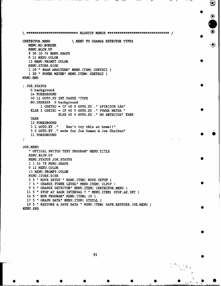
AA°AAAAA.°L'AAAAAAAAAAAAA NLOSTCP MENUS *********A .**********/
CDETECTOR.MENU \ MENU TO CHANGE DETECTOR TYPESMENU.NO.BORDERMENU. BLOW. UP9 30 10 76 MENU.SHAPE0 11 MENU.COLOR13 MENU. PROMPT. COLORMENU. STORE. DISK1 10 " BEAM ANALYZER" MENU.ITEM( CDETEC11 30 " POWER METER" MENU.ITEM( CDETEC2
MENU. END
JOE.STATUS •0 background14 FOREGROUND50 11 GOTO.XY INT.PAUSE "TYPENO. DEGREES 0 background
1 CDETEC - IF 40 9 GOTO.XY ." SPIRICON LBA"ELSE 2 CDETEC - IF 40 9 GOTO.XY ." POWER METER "
ELSE 40 9 GOTO.XY ." NO DETECTOR" THENTHEN13 FOREGROUND5 1 GOTO.XY ." Don't try this at home!!"5 2 GOTO.XY ." made for Joe Osman & Joe Chaiken"1i FOREGROUND 0 •
JOE .MENU" OPTICAL SWITCH TEST PROGRAM" MENU.TITLEMENU. BLOW. UPMENU. STATUS JOE. STATUS •1 1 24 78 MENU.SHAPE0 11 MENU.COLOR15 MENU. PROMPT. COLORMENU. STORE. DISK5 5 " MOVE SETUP " MENU.ITEM( MOVE.SETUP )7 5 " CHANGE POWER LEVEL" MENU.ITEM( CLPCP } •9 5 " CHANGE DETECTOR" MENU.ITEM[ CDETECTOR.MENU
11 5 " STOP AT EACH INTERVAL ? " MENU.ITEM( STOP.AE.INT14 5 " RUN PROGRAM" MENU.ITEM( JO )17 5 " GRAPH DATA" MENU.ITEM{ GTOTAL19 5 " RESTORE & SAVE DATA " MENU.ITEM( SAVE.RESTORE.JOE.MENU }
MENU.END 0
91
0 0 0 0 0 0 0 .0 " 0

Reprinted from The Journal of Physicil Chemistry, 1992. 96.Copyright Oc 1992 by the American Chemtical Society and reprinted by permission of the copyright owner.
Laser Chemistry of Organometallics as a General Synthetic Route to Metal Clusters
J. Chaikem. A. J. Casey, a&d M. VMauica* 0Deparimen, of Chemistry. Syracue Universay. Syracue. New York 13244-4100'Received: November 18. 1991: In Final Form~ January 13. 1992)
We show that gas-phase oraometaiics can be photolyzed us"n pulled UV-Visible Waers to initiate synthesis of metal. clusters.We use tne log-normal distribution function to compare this new method of cluster formation to other meuiods. Cluster=iecaistnibutionsw rouced using this new method bear a remarkable similarity, to those prOauom using nacl beami expansion
metnods. Although theme as ceViatuof from this distribution. thate growth methods would seem to invotve costesosnot growthmnccanisnis as coposeu to Citwald ripening. Possible reasons for the deviation from a log-natural distribution are suggSwed.Lser chemistry allows synthesis of gas-phase metal clusters because of the very high pressures of metal atoms attainableusing muttitihoton dissociation of organometallics.
Introduction produced using the nozzle beam expansion methods. AlthoughClusters- of atoms and molecules span the transition from there is some devation from this distribuuion. both methods would
quantum mechanical to classical objects and have been syn. seew to involve coalescence growth' as opposed to Ostwald ri-thesized;' using sintering and heated wire evaporation, laser pe-- LawU chemistry allows synthesis of gas-phase metalvaporization combined with a supersonic expansion.4 and related clusters because of the very high pressures of metal atoms at-methods$ which utilize ovens. We show that gas-phas orgaren tamnable using multiphoton dissociation of organometallcs.0metallics can be photolyzea using pulsed UV-visible lasers to Multiphoton dissociation of organometallics is widely known"-2
initiate synthesis of metal clusters. We use the log-normal dis to produce free meta atoms, ions. and other fragmentatuontribution function:"'~ to compare this new method of cluster products which coalesce to produce LCVD films.J.14 Becauseformation to the other methods. Cluster size distributions pro-duced using this new method bear a remarkable similarity to those
(7) Machlin. E_ S. 7thermodi'aamwzend Xarnetict Rielevaitt to Hat~enalsSciem. Giro Presr Croaon-oii-iudson. 1991.11) Pool. R. Science 1996. 24.!.1186-1183s. (1) Houeatopp. J.; Raomey. D_. Samoriski. B.: Chaikcn. J. Chint. Ph's.~21 Granovist. C. G.. Buhrinan. R. A. Solid State Com~mun. 1974. 15. Lett. I91. 116. 380-386.
Z3-126. (9) Hosniogpp. J1.; Rcamey' D.; Samortski. B.; Chaiken. J. 1. Chein. Phjyi.:3) Granovii:. C. G. Buknnan. R. A. J. Caie!. 1976. 42. 477-479. 1914.85. 333 1-3337.141 EISva MI. A J. Phys. Chein. 19"1. 95. 3599-3906. (10) Homeabaom J.;Rooney. D..:SaronaskiS.B.,Ch~likmJ. J. Chem..PAm
15) Klots. T. D.: Winier. 11. J.: Parks. E. K.. Riley. S. IJ.1 Chemn. Phi's. 191G.55. 3326-3330.19".9O.9Z!:0. (11) Samoeaski. B.: Chaken I. J. Chemn. Phvis. 1919. 90. 4079-A09.
t6) Siano. l0 S. J. Chem". Edaw. 1972. 49. 755-757 92(12) Sattonsik. B.: Chatikan. J1. Pkn's. Rev. At 1958. 35. 3498-3503.
)022-36S4l9212096.3'133S03.00IO V 1992 American Chemical Society

TeJunlo hsctChemisrv Vol. 96 No. 3. :99 Letters
Tigu e 1.oSannngaetron Phicrotavi of Vrnorn maiu 3 92
on Qart Siostate.Augr mtarn stectoscvy nowstrit te oign
FFigure 2. Traasnssio erectron micrograonh of transparentin ovarnum jiMr. flunts auostrate aiufer onetro speirocop sridws Nodule are Oflic t
these films are cominosea of clusters. it is reasonatile to suaspc fimannroiecyonooprgis.Nuesrencalon,hat they could have unusual ooticai ana eiectricat orotieries.-PluretSKy and Dem~vanen.Ko- ren~ortea over a vcar ago triat na- Ut9**%
nosecono excirner laser Poui5se couita tie usea to coratice cioucsof metal clusters ana uitrafine particles from 2as-onase netaicaroonvis. Their estimate on tne size ana snapre oxtintiution was-=as on moomiitv measurements in wnicn tne numoer Ocnsitvesa-ria tempe'*-,tures (,, me ooouiauions orcocucca couic not oc Knownmcoeoenntentiv. Nevertneiess. trneir eviaence :or tne -existence ofiAciusters ania uitrafine varticles was convincing Similar exmcri-:nents were reoortea mucri earlier ny Tam ano. co-wor~c.rý-- ariaomners.11 The Smaile': laser vaporization~suoersonic exnansion
eniu.antia oven oasco versions. nroatuce coinsion-free 2as-coase samnies flaying cluster tiensities of ==i0- cm~ - The new,ecrnniaue promises to allow orooauction 01 eas-onase numoeraensitic-s excedalng ==i0 ciustersicm- using even tne most re-*ractorv ma-tals.
Experimental Section0
Although our Dasic metnod for LCVD has ceen =c-e Figure 3. Transmussion' ciectron micrograph of one of time nonuies atearlier, an extensive cescription 01 our new app~aratus is in m~e magniittimon Orne ciuster is circled to inoicate one orarrneter uselanreparation. Films are aeriosited ov nirecunig a sen .es or masKen. to prolauce une iog-normai poit.unifocusea. ==i0-mJl. :oG-ns. 308-nm .aser wuises iLamnota IKA~iC temperature vapor pressure of >30 ann '=44 mTor-. :les-ec~tivem,.E.MG 10I11 into a cnamocr containingz an or~arnometailrc '.atoor The iiilms usen : in -,--s szuaoý .Acre acoeositeca o~er -W nt:n usingzana Dmoossv otner gases. The laser entrance wintiow ana,~ 20 ae uss .integrni otc ~t n ae erA~inniow are ine suostrates. or otner coiects can. oe pracec in ,,nc
.;-u t seve s sostate Ir laer av~r m,, o, ontct ,. ann witri a staenanm - Torr total Dressure. TEM anc =tctron,.e tosere a sustrtes~fl laer ay ? m' nt cntat tt ff-acuon nata. -,kas coctainen usiniz a jEOL iJEM i insimruc.n:
;umstrt ana tue 2as vnase may oc fiowing or stagnan:, -%itouz Z. -n E -a oana sn e~nErrl6.ne rate of' film 2roat is maximizea wner n suostraes ar-, Scnntins!AulerM Aavrotanausn c -. t~?
plenninrg on connitions. can oc net~ele :n stagnant ccoosition ce::s Resultsover long perions of tmme. Figure ,snows a SEM of a film necolsitena on a ýua,-: -'.rnoo
The orianometailc :recursors emvoloea-n :n ne cueritt sit1~c\ hs lm aene ecicni eal. n ;%
were ailvicyclooentopaievntinum. a-- orenro r :~nas a root; transpiarent metal =:ctroties. -Free-stancning LCV.D -iatinr~uncvcovcta~eny~patium. Eao pecrso na a oom fims ancnioreta onto a stannarn coopier TEM irria can xc seerin______________________________________ Figure 2 at xl1500 magnification. One of those Cflims :s stiown
(1 3) For an overview oi LCI). see !or example Baucr:c. D C'!emical at higher magnification 1X 149 0001 in Figure 3The em-ecirconProctssrni with la~serr. Sprmnsier Beriin. 1986. Spirineer.:lenes in Niatenals diffraction p~attern cn-aracter-istic of that uarticuiar flin containsScience. Voi. 1. For a oavilxam oi our sunoje LC\ D atioaratus see Roone-, reflections-- from onru oiatinum. manifesting a oistrioution o:D; Nexotti. D.. Bvasse. T. Mactro. D. 'vastai . B. Chaimcn. J .ec- pianes ano, cluster sizes. The coexistence or .certain moeroencuiar:Pocnem Soc. 1990. 137 !162-1166 See also Czaikcn. i ýS Patent pae eurstltttcutr o aemc,:tro oz4 971.853. oae eursta .,, lsesntnv unitnrv;
(14) Kopiatz. L. V. SbuL. D K. Chen. Y J Willams R S . Z:,-A. VoueA Dpi. Phi's. L-ell. 198S. ý(3 !"05 At hignest magnification in the TEM. darx regions nan,-ngtn
1IS) Porter. J. D. Heilier. A. Asones. D E. .'aturr 1985. :5.3. appearance of glocutlar clusters can Dc seen with onutrm regionsHeiler. A. Science 1984. ::. '. 141-1148
16) as. .: enu.H JPhvsCne 198 ~ n oetween. As suggestea by tne examnic in tne picture. tnese-117) Dem, van~o. A V . PUMetix -% -k .Szeccrocnmmzca .4cia 1990 . ~~darK regions can De aporoximatea as circuiar ana a cisnroution
509-5 16 of cluster niameters ootainen. The distnbution cor-cstionaine oaiI &I Tam. A.. Mot. G. Harcrr %V Pklts RevLen~I 19"S 2ý pb articular ffru in r-:gure 3 is snown in a ioz-nortnai Dlot i
'19) Yalouzalti. T, Sato. 7Oeawa. 7JCnem rie1980 -: Figure 4 To ooitain mne nrstograrn snown in Figure ~.all .%c,30-27783
01 O Mann. B. E. Shaw. L.Snaw C .1 Chem .(,c -i 1971. :5 :usters wnicn couic --e cicarlv niscernen r-.za wert'I) Xue. 71- Sirous. M i Snuri. D 1., oor . B.CS. nciuneo.
Hficks. R. F: Williams. R F 1 Aim Chem Soc 1989 'zontaciturem Coerrtcais. inc. - \luijmcn ixav uctier irlcustnai t'al,-Box l08. Newourv~oor. NIA. 0!950 Irclcvnone -,S.S. 2 X7\1 X-Ra' . -cer uata.. r.:e No mt(
93

~atrsTeJournat qt Physiwai (.emistrv. sVol. 96. No. 8. 1992 T
'094~musSWU 1 CiiUW rn *nt proauced using a supersonic expansion of Xe:6 are snown(Sw11A IISb P065mg111111 1:V aUnima mzotted togetner in Figture 4. These distributions span a consid-
trabie range of diameters wnitch we oclieve is a measure of theI. number ciensity of atoms present before coaiescence ana their
I-' propensity. i.e.. cross section. to coalesce- All distributions takento from the literature wnitch were orociucco using supersonic ex-
pansions. as well as all those we nave proauced to date using14 AtLCVD. reveal nonlinear iog-normai plots for large cluster sizes.I a ndicaung a deficiencyv oi larger ciusters compared to what is/ expectea based on the log-normai distribution. Since the log-
*~, normat distribution results from a statistical analysis of the ev-olution of the cluster size cistribution. the observed deviation could
* be a consequence of at least a few oeterminisuic factors.* First. we must point out that all of the gas-phase. cluster dis-
0 N qtributions were obtained usingt time-of-flight mass spectrometry(TOF). Since TOF gives only the number of atoms diectly, a
S cluster diameter was obtained bv adding the volumes of the in-dividual atoms and then calculating the diameter corre ponding
A to a single sphere havingt this total volume. The individual atom0 *O 0 op- volumcs-ý* used corresponded to radii obtained from X-ray dif-
.00aA N rcio tdeso uk ytli eas.ads packing artifacts*A A A s* *.* should bemiriumuzed..Weareimnplicitly assuming that the clusters
* 4 * :*are essentiallv filled, but more worx neeas to be done to establish& thils assumptiton as a definite fact. Regardless of this. if the
per centagte of void volume is i ndetiendent of the number of atomsin the cluster, the shape of the plots will be unaffected. In actual7 .act, Using these assumptions ano aotirooriate scaling, a carefiii
0 IQ*o statistical comparison oi the distrioutions produced by expansionsand laser chemistry of oreanometailics snows that they are
A~A~fV% , W ~denucal within exuenmentai error.FigM4 -via otnra iuoclseditiuin rcuab Mass spectrometric determinations of c' ster distributions 0
no t K owcn imetnodarm ann iols uf cluseree idistibtionsX ordisucab always present the possibility tnat a systematic artifact exists..on" :noancmeuoosimare azmen from rexerencs ion.ao Hg distributin because clusters can fraement ourinst ionization. A variety of.roaucca ov nyond oven, excansion method. Pt clusts oroducea usin shmsnvgeneiivot iiieteefc fti o.2mC Cnflsftrv ti 01of pfometathcs.- Al clusters produced by cvaporatioz telitial artifact including reiflectlion TOP mass specumromtry,; andmethod- and also typtcal of sintering method results. Nb. Cu. and Al - threshold photolionization with vacuum UV lasers. Nevertheless'tower, clusters" -.roaucec using laser vaoionzation/expansion method. the possibility always exists that some artifact could exist whichFor the piot correoonoing to ciusters produced usting the evaporation would incorrectly estimate the numoer of clusters present. In our * *methou. a fitted line from thnclierature' is also shown, case. the opmoitec possibility exists. Since the clusters comic into
PtC~Se09INto physical contact before we estimate the distribution, the clustersuw ssw t.4W on o c restse es could copalescie thus overestimating the number of larger clusters
present compared to the nascent stas-ohase distribution produced.The observed deviation from a perfect log-normal distributionsuggests that just the opposite is true. A variety of reasons in-volving; the stability of larger ciusters are also plausible. Forexample. the particular LCVD films used in this study wereproduced such that the laser contacts the substrate during de-position. Thus the distribution of cluster sizes could be a measureof the propensity of certain ciuster sizes to survive repeated ex-posure to the laser.
:2 2 S U 4 A AN1= is V 37 se se IN 41811§Al We also note that the artifact cao, to our LCVO and the2211 21 $2 As id46 4=l S"7gIB.IW3 "a. (¶166 14Weyepaso prouce dinS col b aue b h
Fipmr S. Histogram snowint typical platinum cluster size distribution relatively short period of time during which coalescence growthpronuctit usine laser cneritstry of organometailics for one t free-stanoing could take place. This would lean to a deficiency in larger clusterfilm Lsing voiume of -ahere consistent with diameters shown and sizes relative to proomses which are not kinetically quenched. The
ensitv of ouilt platinum, the approximate number of atoms in eacn organometallic pressure is at least several orders of magnitudeciuster is mien. greater than the room-temperature vapor pressure of bulk plat-
inum. When the lase pulse passes through, the vapr- is convertedDiscussion to atoms and fragmented moiecules. Since the c't..ctive tem.-
Granovist and Buhr-nan;.-3 originally applied the log-normal perature of the laser produced cloud is in the range of 101 K. ifdistribution to differentiate between cluster size distributions only because that would be the temperature needed to produceproduced by a coalescence growth mechnmism and those piroduced ant equivalent pressure of platinum atoms starting from bulkby other mechanisms sucn as Ostwald ripening. One cluste'r platin um, and the coalescence occurs in the 10- 1-0-'s time scale.distribution typclothsprdcdboumehontyia the cooling rate associated with LCVD is in the range 10O-109of those obtained using standard sintering and evaporation K/s. Because of the similarity between our LCVD log-normalmethods.: one typical of all those:4-1 produced using the Smalley plots anti all the others, the data no support the idea that the clustermnethod.-' one p roduced usinst an exoansion/oven method.-- andti__________________________
_________________________________ (25) Haberland. H.. Kornmncier. H.. Lanitosn. H.: Oseliwaid. M.: Tanner.G. J. Chein. Soc.. Faraday' rrans. 1990. f6. 2473-2491.,23) In addition to 'nose in ret 4 see: Martin. T. P.. Bergmann. T.. t 26) liaberland. H4.. Kolar. T. Retners. T Phsrs. Rev. Lett. 1989. 63.
Gohlich. H . Lanste. T I Phvs Chem. 1991. 93. 6421-6429. ',219--122:..:4) Dietz. T. G . Ouncan.m A .. Powers. D. E.: Smalley. R. E. J. Chem 1271 Mahan. B. Unwenits Chring sirt: -no ed . Addison-Wesley: London.
P'v.1981.7-9.0. 1S 969: p 564
94
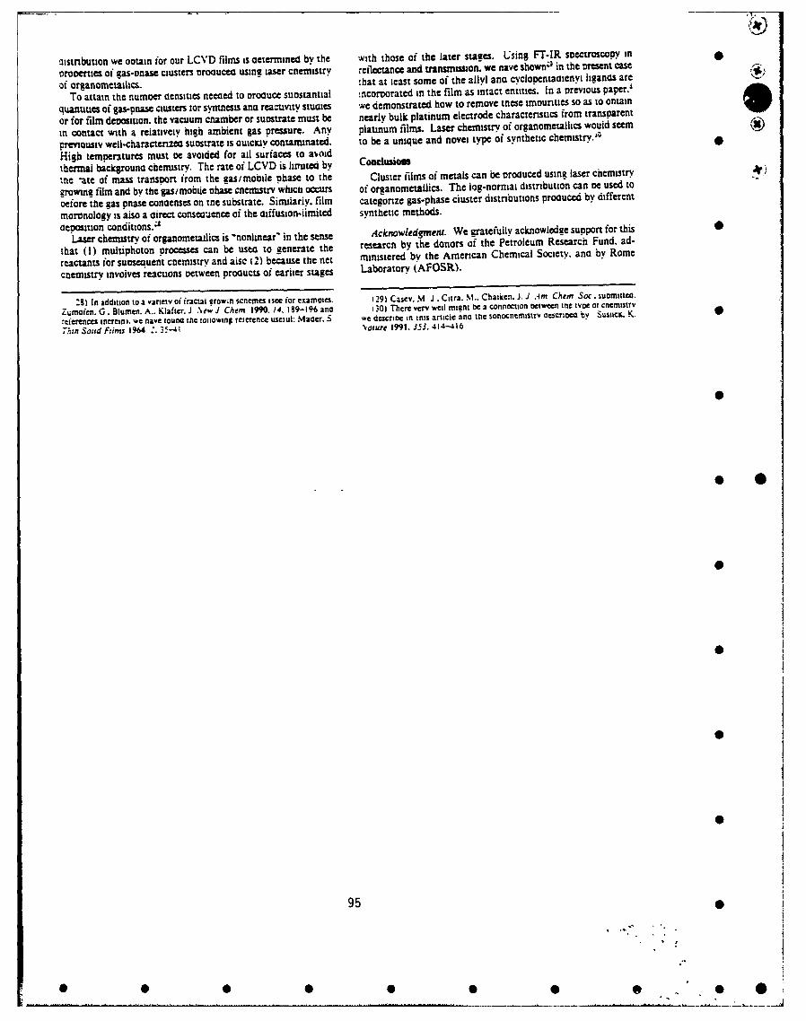
.3istribution we ootain for our LCNVD films is cetermined by the with those oi the later stages. Using FT-IR spectroscopy in
oroverties oi gas-onase clusters nrociucea. using taser cnemistry reflectaric and transmilssion. we nave showwi in the present case
of arganameitailics. -hat at least some of the allyl ana cyclapentatiienyt liganas are
To attain ttie numoer tiensiues neeced to orcouce suastantial mncorvorated in the film as intact entities. In a previouis paper.'
quantities of gas-poa~s ciusters tar syntnests ana reactivity stuaies we demonstrated how to remove inese impurities so as to ontain
or for film deposition. the vacuum cnamber or suostrate must be nearly bulk platinum electrode characteristics from transparent
in contact with a relatively high ambient gas pressure. Any platinum films. Laser chemistry af arganomemaillcs would seem
Previousiv well-charactenzea suoistrate is auicKiv contaminated. to be a unique and novel tyPe at synthetic chemistrY.3
High temoeratures must oe avoided for ail surfaces to aiaidthermal backgrouna chemistry. The rate of LCVD is limiuted by CoDclsii~Ow
ute -ate of mass transport friom the gasimobile phase to the Clus~er films of metals can be Droauced usine laser chemistry
growing ijim and by the gas/mobtie phase cnemitrv which occurs of organometallics. The lag-norniai distribution can oe used to
oefore the gas pnase conaenses on tne substrate. Similarly, film categorize gas-phase cluster distributions proatuced by different
moranology is also a airect conscuence oi the aiffusion-ii~mited synthetic methods.aeposition conditions.:
Laser chemistry of arganonietaiics is -nonlinear" in the sense AcknowledgwMci. We gratefully acknowlodge support for this
that (1) multiphoton processes can be usec to generate the researcn by the donors of the Petroleum Research Fund. ad-
reactants for suoiscotent, cnemnistry and aise (2) because the net ministered by the American Chemical Society. ana by Rome
ctiemistry, invoives reactions oetw .een proaucts of earlier stages Laboratory (AFOSR).
:91 In addition to a variety of fractai erow~h scenems i see for czamovies. (29) Casev. NI J . Citra..M.Chaiken. J1. J Am Chem Soc. suomittea.
Zumnoien. G. Biumten. A.. Kiafter. J N\ew J Chem 1990. 14,1I89-i196 and 1 301 There very weil migmi oc a connectionl Ociween Inc tvoe at cncmistrv
?tereinces toereini. we rave biona ine ioiaowing reterenct usetui: Mader. S we descrioc in tnis article ano Mec sonocntmisirv escnoe bv Sust=e K. 0
'h:n .Soud Ftims 1964 3 3-1 Naur 199. .3j3.414-416
950
0 0 0 0 41

',onlinear interface optical switches based on pnotofr3CUv0 thin films
M. J. Casey and 1. Chaiken
Department of Chemistry, Syracuse UniversitySyracuse. New York 13244-4100
J. M. Osman
Rome Laboratory/OPBGriffiss Air Forct Base
Rome. New York, 13441-5700
Sftj S.ASC
We present the nonfiincar interface optical switch in the context of digital optical compuung applications. ImpIicatlons
with recara to materials destgn and development and switch evaluation arc discussed. A specific class of materials synthesized
usina iaser cncmnisry of oreanometallics is presented. Embodiments of this type of switch have considerable potenual for meeunga
many of the required desien cnrcna for practical implementation of digital opucal computing devices.
INTROD.UCTION
We are dcveioming and evaluating opucal switches for optical computing appiicauons which must meet a broad range ot
destin criteria. Optical switching based on the so-called "nonlinear interface' was reported years ago, however finding an 0
,,mboaiment of that phenomenon which fullfills design criteria for acttal devices remains unreported. We describe recent work on
the evaiuation of nonlinear interface optical switches(NIOS) based on thin films. First we give some background concerning thephenomenology of these switches and films and the concept of a nonlinear interface switch in the context of digital optical
computing. We then describe the embodiment we are striving to fabricate which involves a slight digression into materials
chemistry. Finally, we briefly dcscribe current efforts toward physical evaluation of the films as switches.
BACKGROUND-NO!-
Fi•rure I ,yives the basic idea of an NOIS. Light impinging on an interface between two media having different indices of
refracuon is partly reflected and partly transmitted by the interface. The percentages of the incident which are reflected and
transtmtttea arc determined by the difference in index of the refractions present at the interface. If one of the media is
photorefractive. i.e. its index of refraction depends on the amount light which is present. It then becomes possible opucally, to
equaiizc the indices of refraction on either side of the interface and thereby control optical switching by controlling the amount oi
haiht rctzcctcd at the interface. A switch could be composed of a film of a photorefractive material on a ransparcnt substrate.
Stanoard Fresnci coefficients adequately model the observed optical performance of such films provided one knows the opucal
properties of the substrate. film. and air.
The optical properties of the film and substrate have to be appropriate to allow equalizauon of their indices of refraction
bv incident ivht. Such a dev:cc will never be a bistable device2 regardless of the properties of available materials. The speed of the
switch would depend of the temporal properties of the material(s) nonlinearity. If this were a nonresonant response, the response
could be subpicosecond in both nsc and fall. Similarly, the power. spectral, spa"al and other switch propertues would all depend
on the material properties. Archetectural considerauon of this type of switch has been thoroughly discussed by others3 with the
general conclusion being that the NOIS has considerable potential for digital optical computing appiicauons. Using light from
one source to control the amount of light from a different source being reflected at the interface, it is possible to construct any
kind of logical function.
Since the original proposal of the NOIS by Kaplan. and the later proof of principle work by Tomlinson and coworkers.
the underlying phenomenon of the NIOS has been used in a variety of other applications. Aspnes and colleagues4 have used a
phenomenon they dubbed "rcflectance-dtfference" spectroscopy to monitor monolayer deposition of gallium and arsenic in MBE
appiicauons. Henon and coworkers 5 have used a technique they call "Brewster Angle Microscopy". Yamamoto and others have
used rc:lection-absorption spectrometry for similar applications.
"0194077.2-092154 00 SPIE Vol. 1626 Nonlinear Optics III (19921
9600.-8 9d-O72"G92154O0 9
0 0"0 .. .' 0
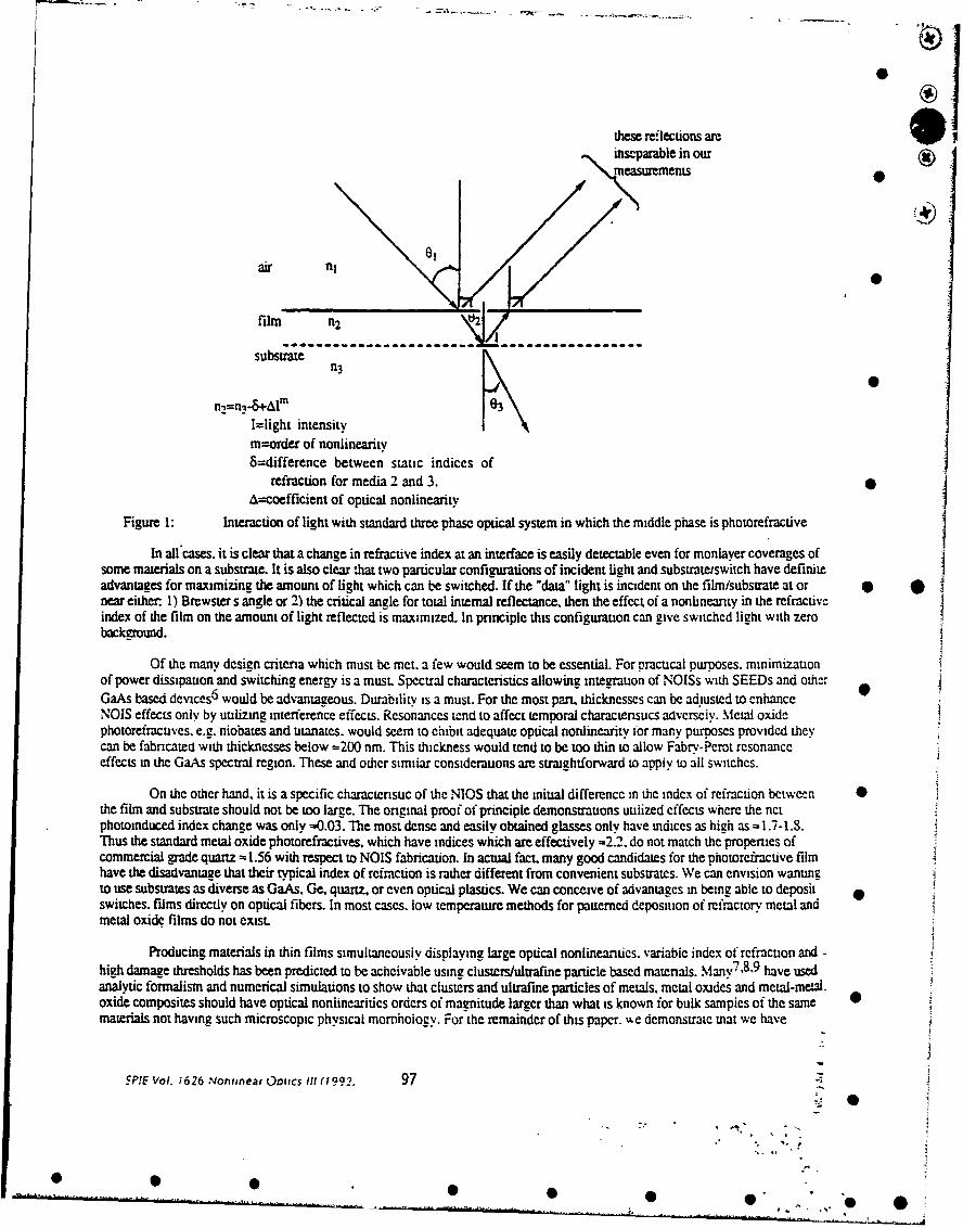
-•-@--
*
these reflections are 4 1ins-parable in our ()measurements
air flj
film n2 \ 2
substraten3
n)=n-&-Al\0K
I=light intensitym=order of nonlinearity8=difference between static indices of
refraction for media 2 and 3.A=coefficient of optical nonlinearity
Figure 1: Interaction of light with standard three phase optical system in which the middle phase is photorefractive
In all cases, it is clear that a change in refractive index at an interface is easily detectable even for monlayer coverages ofsome materials on a substrate. It is also clear that two particular configurations of incident light and substrateiswitch have definiteadvantages for maximizing the amount of light which can be switched. If the "data" light is incident on the film/substrate at or *near either. 1) Brewster s angle or 2) the critical angle for total internal reflectance, then the effect of a nonlineanty in the refractiveindex of the film on the amount of light reflected is maximized. In pnnciple this configuration can give switched light with zerobackground.
Of the many design criteria which must be met. a few would seem to be essential. For pracucal purposes. minimizauonof power dissipation and switching energy is a must Spectral characteristics allowing integration of NOISs with SEEDs and otherGaAs based devices 6 would be advantageous. Durability is a must. For the most part, thicknesses can be adiusted to enhanceNOIS effects only by utilizing interference effects. Resonances tend to affect temporal charactensucs aavcrsciv. Metal oxidephotorefractuves. e.g. niobates and utanates. would seem to ehibit adequate optical nonlinearity for many purposes provided theycan be fabricated with thicknesses below =200 nm. This thickness would tend to be too thin to allow Fabrv-Perot resonanceeffects in the GaAs spectral region. These and other similar considerauons ame straightforward to appiy to all switches.
On the other hand, it is a specific characteristic of the NIOS that the initial difference in the index of refraction betweenthe film and substrate should not be too large. The original proof of principle demonstrations uuilized effects where the netphotoinduced index change was only =0.03. The most dense and easily obtained glasses only have indices as high as =1.-1.8.Thus the standard metal oxide photorefractives. which have indices which are effectively -2.2. do not match the properties ofcommercial grade quartz - 1.56 with respect to NOIS fabrication. In actual fact. many good candidates for the photorefractive filmhave the disadvantage that their typical index of refraction is rather different from convenient substrates. We can envision wantingto use substrates as diverse as GaAs. Ge, quartz, or even optical plastics. We can conceive of advantages in being able to deposit .switches. films directly on optical fibers. In most cases. low temperature methods for patterned deposition of refractory metal andmetal oxide films do not exist.
Producing materials in thin films simultaneously displaying large optical nonlinearities. variable index of refraction and -high damage thresholds has been predicted to be acheivable using clusters/ulrafine particle based materials. Many 7 ,8'9 have usedanalytic formalism and numerical simulations to show that clusters and ultrafine particles of metals, metal oxides and metal-meWa.oxide composites should have optical nonlinearitics orders of magnitude larger than what is known for bulk sampies of the samematerials not having such microscopic physical momhoiogy. For the remainder of this paper. %%e demonstrate mat we have
SPIE Vol. 1626 Nonitnear Ootecs III (1992, 97
'-

= rdcdfilms of metal and metal oxide clusters. These films also have considerable flexibility' in the bulk indices of refraction* whih the display. 'We then describe our earliest efforts at evaluating these films as optical switches.
LASER CHEMISTRY OF ORGANOMETALLICS• Metal/platinum cluster films
Clusters 0 of atoms and molecules span the transition from quantum mechanical to classical objects. Clusters andultafine parucles have been synthesized1 1,12 using sintering and heated wire evaporation, laser vaporization combined with asupersonic expansion 13 . and related methods 14 which utilize ovens. We show that gas phase organomnetallics can be photolyz"dusing pulsed UV-visible lasers to initiate synthesis of metal c'usters. We use the log-normal distribution function1 1,12.15 tocompare this new method of cluster formaton to the other methods. Cluster size distributions produced using this new methodbear a remarkable similarity to those produced using the nozzle beam expansion methods. Although there is some deviation fromthis distrbuuon. both methods would seem to involve coalescence growth 1 6 as opposed to Ostwald ripening16 . Laser chemistyallows synthesis of gas phase metal clusters because of the very high pressures of metal atoms anainable using multiphotondissociauon of organometallics. O
-% diagram of the basic apparatus used to perform LCVD has been presented elsewhere1 7 . As can be seen in Figure 2,platinum fiims >550A thick and exhibiting >70% transmittance across the enture UV-visible spectrum can be synthesiz-ed usinglaser chcmical vapor deposition(LCVD) 17 . Such platinum films have been called "transparent' metals18 because theysimuitaneously exnibit metallic conducuvity and optical transparency. The transparency is thought to be a direct consequence of102 nanomcter scale morphology shown using scanning electron microscopy(SEM) in Figure 3. Because of the presence of the 0clusters. and the uiffusion controlled deposition conditions, voids are present in the films through which incident light ischannelcd. Smoom contiguous platinum films become opaque18 at ,310 A average thickness. The clusters are thought to behighly polarizable 9 thus forcing incident electric ficlds into the voids.
4% N
Figeure ?Potograph of "'Lransparcnt" platinum film on a quartz substrate which is resting on a book page
0
0O. 2,gin
Figure 3: SEM of platinum film on quartz substrate. Dark regions are voids which extend to substrate.Light regions are nearly pure platinum.
98 SPIE Vol. 1626 Nonlinear Optics 1ll (1992)
0
0 0 0
0 000 0 "0

PuretsKy and Demnyanenko 20 rr,)ored over a year ago that nanosecond excimer laser pulses could be used to produceclouds of metal clusters and uliafine p.-. idCes from gas phase metal carbonyLs. Their estimate on the size and shape distributionwas based on mobility measurements in which the number densities and temperatures of the populations produced could not beknown independently. Nevertheless. their evidence for the existence of clusters and ulirafine particles was convincing. Similarexperiments were reported much earlier by Tam and coworkers 21 and others2 2. The Smalley laser vaporizauonisupersonicexpansion technique. and oven based versions. produce coliision-free gas phase samples having cluster densities of =010 cm- 3 .The new techmque promises to allow production of gas phase number densities exceeding - 1015 clus-rs/cm3 using even the mostrefractory metals.
The organometallic precursors employed in the current study were allyl cyclopentadienyl platmum2 3 and trimethylmethylcyclopentadienyl platinum24 . Free standing platinum films anchored onto a standard copper TEM grid c,, be seen inFigure 4 at high magndicsuon(x 149,000). The electron diffraction paemtn characteristic of that particular film containsreflections 25 from only platinum manifesting a broad distribution of planes. At highest magnification. dark regions having theappearance of globular cluswi-z an be seen with bnrghtcr regions in between. These dark regions can be approximated as circularand a distribution of cluster diarneters obtained. The distrbuuon corresponding to the particular film is shown in Figure 5. Wecannot say yet whether the clusters are hollow or solid.
0
- .i
Figure -1: TEM of platinum cluster film showing diameter used to construct histogram of cluster stzc-s
00
32 42 53 53 74 85 95 'OF 1'16 27 '37 '48 158 169 "S* oiametenAlZS 52 88 1- 22;2 : =2 I= SC 7- o 1400 1 "CC 2-= atoms (Xl00' •
Figure 54: Histogam of cluster sizes produced in transparent plaunum film.
Granqvist and Buhrman 11. 12 orginaily appiicd the iog-normal distribution to differenuate bctwecn ciustcr sizedistributions Droduced by a coalescence growtr, mechanism and those produced by other mechanisms such as Obtwald npening.One cluster aistnbution tvpi.ai of those produced by our mcmnoo. one typical of those obtaincd using standarc sintering andevaporation metnodsl,. cnetypical of afllthosV _6 rocuc,-, using the Smalley method. one oroducco us,:n an cxpansicn, ovcn
SPIE Voi. ;626 .Nonjinear Ootics III (1992. 99
0 0 S 0.-.
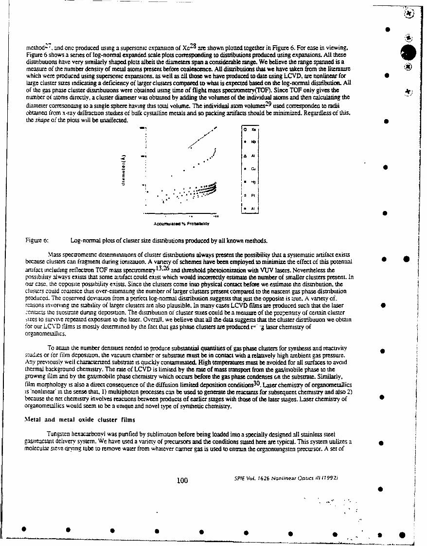
method'-. and onc produced using a supersonic expansion of Xe 2 8 are shown plotted together in Figure 6. For ease in viewing,Figure 6 shows a series of log-normal expanded scale plots corresponding to distributions produced using expansions. All thesedistributions have very similarly shaped plots albeit the diameters span a considerable range. We believe the range spanned is ameasure of the number density of metal atoms present before coalescence. All distributions that we have taken from the literaturewhich were produced using supersonic expansions. as well as all those we have produced to date using LCVD, are nonlinear for 0large cluster sizes indicating a deficiency of larger clusters compared to what is expected based on the log-normal distribution. Allof the gas phase cluster distribuuons were obtained using time of flight mass spectrometry(TOF). Since TOF only gives the 4number of atoms directly, a cluster diameter was obtained by adding the volumes of the individual atoms and then calculating thediameter corresonaing to a single sphere having this total volume. The individual atom volumes2-9 used corresponden to radiiobtainea from x-ray diffracuon studies of bulk cystalline metals and so packing artifacts should be minimized. Regardless of this,the shape of the piots will be unaffected.
0 iX@- ." AM
A A]
E
* * ' - - ~Pt 1
& j AI ]
Accmuwated % Probahl~t¥
Figure 6: Log-normal plots of cluster size distributions produced by all known methods.
Mass spectrometric dcterminauons of cluster distributions always present the possibility that a systematic artifact existsbecause clusters can fragment during ionizauon. A variety of schemes have been employed to minimize the effect of this potential •artifact including reflectron TOF mass spectrometry 13 .2 6 and threshold photoionization with VUV lasers. Nevertheless thepossibility always exists that some atifact could exist which would incorrectly estimate the number of smaller clusters present. Inour case. the opposite possibility exists. Since the clusters come into physical contact before we estimate the distribution, theclustcrs could coalesce thus over-esumaung the number of larger clusters present compared to the nascent gas phase distributionproduced. The ooserved deviation from a perfect log-normal distribution suggests that iust the opposite is true. A variety of.reasons invoiving the stability of larger clusters are also plausible. In many cases LCVD films are produced such that the laser •.:ucntas uwe sutostrate during depositaon. The distribution of cluster sizes could be a measure of the proensity of certain cluster,izcs to survive repeated exposure to the laser. Overall. we believe that all the data suggests that the cluster disiributuon we obtain.or our LCVD fidms is mostly determined by the fact that gas phase clusters are produced . '-g laser chemistry oforganometallics.
To auain the number densities needed to produce substantial quantities of gas phase clusters for synthesis and reacuvity 0stud;es or for film deposition. the vacuum chamber or substrate must be in contact with a relauvely high ambient gas pressure.Any previousiy well characterized substrate is quickly contaminated. High temperatures must be avoided for all surfaces to avoidthermal background chemistry. The rate of LCVD is limited by the rate of mass transport from the gas/mobile phase to thegrowing film and by the gas/mobile phase chemistry which occurs before the gas phase condenses on the substrate. Similarly,film morphology is also a direct consequence of the diffusion limited deposition conditions 30 . Laser chemistry of organometailicsis nonlinear' in the sense that. 1) multiphoton processes can be used to generate the reactams for subsequent chemistry and also 2)because the net chemistry involves reactions between products of earlier stages with those of the later stages. Laser chemistry of 0organometallics would seem to be a unique and novel type of synthetic chemistry.
Metal and metal oxide cluster films
Tungsten hexacarbonyl was purified by sublimation before being loaded into a specially designed all stainless steelgas/reactant delivery system. We have used a variety of precursors and the conditions stated here are typical. This system utilizes a 0molecular steve dring tube to remove water from whatever carrier gas is used to entrain the orgaontungsten precwsor. A set of
100 SPIE Vol. 1626 Noniinear Otics ill (0992j
0
*000 0 0 0 0 0

MKS capacitance manometers and isolable chambers of known volume were used to measure pamral and total pressures and flowrates in the delivery system and in the deposition cell. Although this apparatus will be described in greater detail later3 1, forpresent purposes it suffices to point out that. utilizing a series of micrometer valves and lengths of tubing with various internaldiameters. the total pressure, flow rate. gas stream composition and temperature could each be independently adjusted.
Figure 7a shows a TEM of a free standing tungsten film deposited by LCVD directly onto a TEM grid at x 113,000magnification: globular clusters are clearly visible. Figurt, 7b shows an electron diffraction pattern obtained from th: 4)conglomeration of clusters imaged in 7a). As is typical for diffracuon patterns obtained from many such conglomerations, the nearcoaiescence of the diffracuon rings into spots presents an interesting comparison with the results of Mader' 2 and Aspnes. 3
Observation of "implied" rngs is consistent with the idea that our films are composed by cond nsauon of clusters of varyingsizes. The spacings between the rings were analyzed and only interplanar spacings of tungsten are evidentE3. These spacings wouldseem to be characteristic of the environment inside the clusters. The tungsten clusters are produced using 20 millitorr of tungstenhexacarbonyl at 621C with argon added to produce a total pressure of 70 mtort in the deposition cell. This pressure is lower thanthe vapor pressure of bulk tungsten hexacarbonyl at the same temperature because we are working in a flowing cell. Figures 7cand 7d show essentially the same data obtained for tungsten oxide clusters. These clusters were deposited using the same partialpressure of tungster, hexacarbonyl but with the rest of the total pressure being composed using 02. For the oxide clusters, thediffuse quality of the rings suggests less order within the clusters as well as a distribution of sizes. Raman spectra of films 0comnosed of these clusters have extensive structure below =-400 cm-1 but absolutely no hint of the well known, and extrcmelystiong 700-900 cm- 1 features indicative of the presence of W0 6 octahedra. Auger analysis internally calibrated against authenticW. WOO2 and WO3) of these oxide films reveals an average W:O stoichiometry 1:1.5 which is a factor of -10 below the gas pnaseratio present during LCVD. The film W:O ratio vanes widely from spot to spot on the film and can range from = i:2.5 to neariy1: 1. Measurements of the temperature dependence of the resistivity of 200 nm thick films on quartz in air reveals irreversiblechanges occumng at temperatures as low as = 100'C. The resistivity of nascent films. which are semiconductors, exceeds that oi •poivcrystalline tungstate films although the inmived band gap(.15 eV) is typicai3 5 .
The single most important aspect of all the materials describe above is that the bulk indices of refraction can be chosenby deposition condiuons. The platinum films typically have low power indices of refraction(6328A) in the range of =2.0 comparecto a value for bulk plaunum of =3.8. Similarly, the index of refraction obtained for the laser deposited tungsten and tungsten oxidefilms using a CW HeNe laser range from nearly 1.0 to 2.2. The bulk refracuve index for sputtered pclycrvstalline tungsuate films • *is in tne range of 2.3 to 2.5. In all cases. the variation in index of refracuon in easily rationalized" 8 on toe basis of the effectivemenium theory and the void volume of the films. Since deposition of the films is entirely diffusion controlled, depositionconditions determine the void volume which in turn affects the bulk index of refraction. As detailed above, this sititation isextremely useful for engieenng film for NOIS appitcations.
C0
Fietire 7 TEM and electron dlffracuon cnaracterizauon of tungstenta b) and tungsten oxidcc.J) cluster fiims
"_PIE Vol. 1626 Nonlinear Ootics, it 992 101
F0 0 0 00 0 0 @

Ontical Switch Evalu2tion
Evaluation of potential !witches fabricated using films of the above materials is currently in progress and so only thegenerai ideas will be presented here. Two configurations arc used as embodiments of switches. The light can impinge on the filmand then tne suostrate as suggested by Figure 1. in all cases, the reflections from the air-film interface cannot be separated fmom thereflecuon at the film-substrate interface. However, careful nearly zero background measurements can be made when the angle ofincidence is adiusted to be near the effective Brewster angle for the film-air system. Alternatively, it is possible to proceed with anlexacuy reversed situauon. In this case the fight enters the switch from the uncoated side of the substrate and is propagated until itý.ncounters the film-subsrate interface. The angle of incidence of the light with the substrate is varied until the critical angle fortoal internai reflection for the iight at the film-substte interface is acheived. In this case the percentage of Light transmittedacross ue substrate-film-air interface is measured as a function of incident power. This latter configuration is also a nearly zerobackgmuna measurement and in practice is less sensitive to photorefractive effects at the film-air interface.
In either configuration, the starting point for switch evaluation is contained in Figure 8 which shows results of ameasurement of the percent reflectance of the film-substrate combination as a function of incident angle. The film is composed ofthe tungsten oxide clusters shown above. The simplest point to make is that if the shape of such a curve is a function of thepower oi Le incident light, then one of the materials in the three phase system is photorefractive and switching is possible. Wehave ocen engaged in measureing the power dependence of the shapes of such curves at a variety of wavelengths. We have beenusing moae-iocked 5 14 nim pulses of - 100 psec durauon obtained from an argon ion although measurements at different.%avcicr.tns wril be conducted soon. Once a photorefracuve effect is detected, then the switch can be evaluated in the typical pumprDOc mcnoa in wnich a purse of light is used to set-upo e photorefractuve effect and a later pulse. ,he probe/dama arrives delayed
to manitest we oreseance of the earlier pulse. These measurements are the starting point for complete spectral, spatial. temporaiana encrzeuc evaiuatuon of NOIS devices.
2000
'800 U
800- m U a
i400
* 0
120 25 30 35 40 5 50 55 60 - '0
~e~IF 114111 A"91000
Figure 's Typical power reflected from a tungs~en oxide cluster film as a function of angle of incidence.
Optical switches b-,sed on nonlinear interfaces have considerable promise towards meeting the myriad of design criteria forproducmge devices relevant to digital opticda compuung applications. Novel materials which can only be synthesized using la=echemist., of oreanometallics have a number of unique advantages for the design and fabrication of such switches. Switch•,-valuation is proceeding using metal and metal oxide cluster films which have been predicted to be highly photorefractive.
Acknowledgements
Wegatefully acknowledge that this researc was supported by Rome Labs. Syracuse University ad by the Donors tothe Pe,.-, eurn Research Fund as Administered by ,.he American Chemical Society•
"102 5PIE Vol. 1626 Nonlinear Optics III (1992)
800
600
• • • •• •• ' •

6
P. W. Smith. W. J. Tomlinson, P. J. Maloney, J. P. Hermann, IEEE J. Quant. Elec., QE-17, 340-347(1981) andreferences therein
2 D. R. Andersen and J. J. Reg;n. J. Opt. Soc. Am.. A, 6. 1484(1989) and references therein
3 R. Cuykendall and D. R. Andersen, Opt. Commun. 62, 232(1987) j
4 D. E. Aspnes, IEEE J. Quant. Elec. 25, 1056-1063(1989)
5 S. Henon, J. Meunier, Rev. Sci. Instrum.62. 936-939(1991)
6 Nicholas C. Craft. M. E. Prise, La."r Focus .Vorld. May 1990 pp. 191-200 and references therein, see also H. Dammannand K. Gorer. Opt. Commun. 3 31`(1971)
see Eichi Hanamura. Ph,',. Rev. B.. 37. 1273-1279(1988-I)
8. A. E. Neeves. M. H. Biimboim. Opt. Lett. 13, 1087-1089(1988)
g H. Chew. M. Kerker, I. Opt. Sci. Am. B., :. 1025-1027(1985), M. Kerkcr. J. Colloid and Interface Sci. 118, 417-421(19,), )M. -,Z kcr. J. Opt. Sci. Am. B.. 2. 1327. '329(1985) see also reference 19 below.
10 Rober.i' ,. Scic-,ce24. 1186-11W,1990)
11 C.G. ":. :':it and R. A. "1uhrm:an. So".| State Cor:-mtin. 18, 123-126(1976)
12 C.G.Grl"ovistanaR ' i,%" an Journal of Citalysis 42, 477.479(1976)
13 EI-Sayed, M. A. J. Phy" Z2..m. 95, 3898-3906(1991)
14 Klots, T. D., Winter. B. J.. Parks. E. K., Riley, S. J. J. Caem. Phys. 92. 2110(1990)0
15 Siano. Donald &. ' Chem. Ed. 49.'755-757(1972)
16 Machlm. E. S. "Thermodynamics and Kinetics Relevant to Materials Science.'. Giro Press. Croton-on-Hudson. 1991)
17 for an overview of LCVT'1 see for example D. Bauerle. "Chemical Processing With Lasers'. Springer Senes in MaterialsScience. Vol. I(Spnnger, Berlin, 1986) and for a diagram of our simple LCVD apparatus see Dan Rooney. D. Negroti.T. Byassee. D. Maccro. B. Vastag and J. Chaikcn. J. Electrochem. Soc.. 137. pp. 1162-1166(1990). see also J.Chaiken, US Patent 4,971,853
18 Porter. J. D.. Heller, A.. Aspnes. D. E., Nature, 313. 664.666(19E5), Heller, A.. Science 223, 11 1-1148(1984)
19 Das, P., Metiu, H., 1. Phys. Chem. 89, 4580-4687(1985) •
20 A. V. Dem'vanenko, A. A. Puretsky, Spectrochimica Actu., 4,.A, pp. 509-516(19"0)
21 A. Tam. G. Moe, W. Happer. Phys. Rev. Lett. 35. 1630(1975)
22 T. Yabuzaki. T. Sato. T. Ogawa. J. Chem. Phys., 73. pp. 2780-2783(1980) 0
SPIE Vol. 1626 Noninear Owzics III (1992) 103
0 0 0 0 9 0 0 O" ,.," .O 0

23 Mann. B.E.. Shaw. B. L.. Shaw, C. J. Chem. Soc.(A) 3536(19171)
"24 Ziling Xue. M. Jane Strous. David K. Shuh. Carolyn B. Knobler. Herbert D. Kaesz. Robert F. Hicks. R. StanelyWilliams. 1. Am. Chem. Soc. 111, pp. 8779-8784(1989) or contact Strem Chemicals, Inc.. 7 Mulliken Way, DexterIndustrial Park. P. 0. Box 108. Newburyport. MA. 01950 USA (telephone:508-462-3191)
25 ASTM X-Ray Powder Dama. File # 4-0802
26 :n addition to those in reference 4 see Martin. T. P., Bergmann T., Gohlich. H., Lange, T., J. Phys. Chem. 95, 6421-6429(1991)
27 Haberland. H., Kommeter, H., Langosch, H., Oschwald. M., Tanner, G., J. Chem. Soc. Faraday Trans.. 86, 24 73-:481(1990)
28 Haberland. H.. Kolar. T.. Reiners, T., Phys. Rev. Lett. 63. 1219-1222(1989) S
29 \lahan. B. "U'niversity Chcmistry'* page 564.2nd editioniAddison-Wesley, London. 1969)
:n auditon to a variety ot fractal growth schemes, we have found the following reference useful: Mader. S., Thin SolidFilms 2. 35-41(1964)
1 Casey. M. L.. Chaiken. J.. in preparation
32 S. Mader, Thin Solid Films 2. pp. 35-41(1964), S. Mader, H. Widmer. F. M. d'Heurle and A. S. Nowick. Appl. Phys.Lett. 3. 201(1963)
33 D. E. Aspncs. Thin Solid Films 89. pp. 249-262(1982) * 03-4 ASTM x-ray powder diffracuon data f'des( 1967) #5-3086, 5-3087, 5-0431, 5-0392, 5-0393, 2-1138. 4-0806, 5-0364, 5-
0363
Berak. James. M.. Sienko. M. I.. J. Solid State Chem. 2. 109-133(1970)
0
0
1 04 SPIE Vol. 1626 Nonlinear Oolics /1/1 (0 992)
4. ,
0 5 0 0 0 • O *,-.. "O 0

1992 IEEEE
Mohawk Valley Section
M4OHAWK vALL~EY swrm,"$.3Aw-.- -<.- N Command, Control,
Communications,and Intelligence (C31) .
Technology & ApplicationsConference
* '1
ConferenceProceedings
June 1 - 4, 1992
Hosted by:0
h4 lnstitute ofTer.hnolojatutdca/Roie 0
105 0
S, , 0
* O 0 0 0 O 5 0 " "O 0
Session 16 - Photonlcs(Part 3 - Optical Processor Elements)
Chaiman: Mi. James W. Cusa&cOo-Chairinan: Ms. Bud Hiopiaiey
An Optical Nor Gate Basd on Gas-AIGQAs H.tertostlucture Laseirs )
MA Parker and S. Libby. Rome LabororyP. 0. Swanson, Corned UnLvhlsity
PAPER INCLUDED 0
NonlUnear Inerf•ac Optlel Swh•ches Based on Photortsractive Thin Pilms
M.J. Casey, Josean Chaiken, Syracuse UrsiePsityJ'oseph Osman. Rom& Labomloy
0PAPER INCLUDED
Optical •ntarconnecst for High Speed 3.D Signal Processors
Davd Honey ano Franz Haas. Rome LaboratoryCavwo Mdoas arc Harold Craighead, Corned Univ4wily 0
Processing focal plane dataviaop•.ricayireroonnocted 3.- computersaff5Mpotfil for meeting high l•edCcompluattonfl
tequirements without a large power oudget. DOsign, fabrication and tas resuls of one such optical bus, based on reflective
binary optca elements etched in siiicon aria supporting a stacked water 3-0 desin, are discussed.
Massive Holographic lnterconnections for Use Ins Low Energy Optical Procssor 0
David R. Chrisie. Rome Labo'•aorySaphen A, Kupiac. Unive•sity of Alabama at Huntsvile
An N" t!o.og.ao~ic free siace optical interconnection scheme in a special purpose pfocessot architeimure allows ma:ýiv
paraller €a;culatons at very iow energy cost. Intal testing of resolution, error resliency, and diffraction efficiency for a syswm
emcioYinc a 256 x 256 pixei Spatial Lignt Moculator (SLM) and incorpoating noise and crisitalk.minimization techniques 0Is discusuaO.
A Reprogrammable Digital Optical Coptocessior
.anes daL Baita. Pebse=a J. Sussiager and Joseph, M. Osman, Rome Laboraory
A hybr.a elecuo-optical digital computer incorporaing a fully digital free space Optical Programmable Logic Array (C-PLA)as a coorocessor ar oan electronic host is descried. OPLA arch•i•ters are evaluated and compared zo electrical PLAs.Fabrication ccnsiceratirris and applications are discusseca.
0
1060
0 0 0 0 0 0 7*0, •
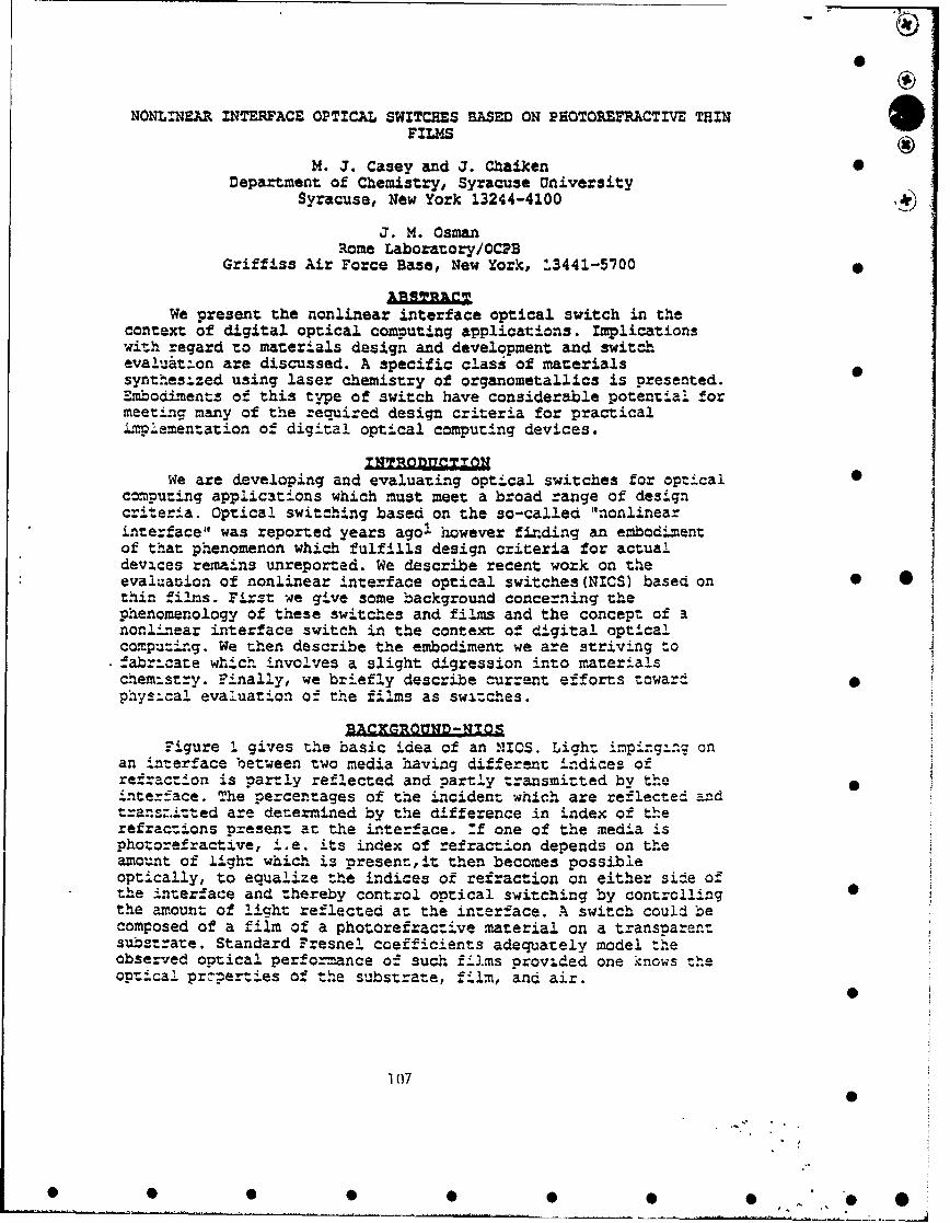
NONLINMAR INTERFACE OPTICAL SWITCHES BASED ON P90TOREFPACTIVE THINFILMS
M. J. Casey and J. Chaiken 0Department of Chemistry, Syracuse University
Syracuse, New York 13244-4100 ,4
J. M. OsmanRome Laboratory/OCPB
Griffiss Air Force Base, New York, 13441-5700
We present the nonlinear interface optical switch in thecontext of digital optical computing applications. Implicationswith regard to materials design and development and switchevaluat:on are discussed. A specific class of materialssynthesized using laser chemistry of organometallics is presented.zmbodiments of this type of switch have considerable potential formeeting many of the required design criteria for practicalLmplementation of digital optical computing devices.
INTRQAMQTT•NWe are developing and evaluating optical switches for optical 0
computing applications which must meet a broad range of designcriteria. Optical switching based on the so-called "nonlinearinterface" was reported years agoI however finding an embodimentof that phenomenon which fulfills design criteria for actualdevices remains unreported. We describe recent work on theevaluation of nonlinear interface optical switches (NICS) based on 0 0thin films. First we give some background concerning thephenomenology of these switches and films and the concept of anonlýnear interface switch in the context of digital opticalcompu=ing. We then describe the embodiment we are striving tofabr:c;te which involves a slight digression into materialschemistry. Finally, we briefly describe current efforts towardphysical evaluation of the films as switches.
EACXGROUND-W!OS
Figure 1 gives the basic idea of an NIOS. Light inpinging onan interface between two media having different indices ofrefraction is partly reflected and partly transmitted by the`nterface. The percentages of the incident which are reflected an-dtransz.i:ted are determined by the difference in index of therefractions present at the interface. :f one of the media isphozorefractive, i.e. its index of refraction depends on theamount of light which is present,it then becomes possibleoptically, to equalize the indices of refraction on either side ofthe interface and thereby control optical switching by controlling 0the amount of light reflected az the interface. A switch could becomposed of a film of a photorefractive material on a transparentsubs2trate. Standard Fresnel coefficients adequately model theobserved optical performance of such films provided one knows theoptica! przperties of the substrate, film, and air.
1(07 ] (]0
0 0 0 0 0 0 0 • 7 O@ 0
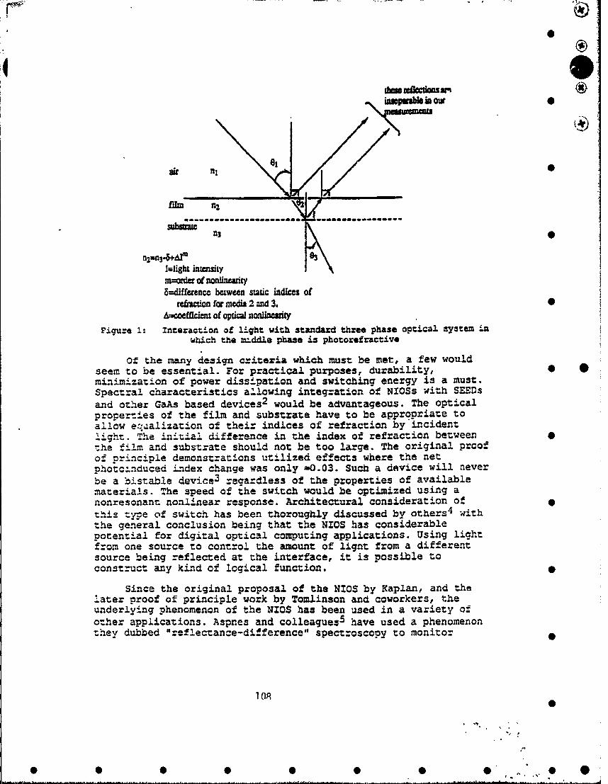
0
iopprab in out
ni
n2=an3-&4hI0ImligbL intensitymoner of nonliniary8-difference between static indices of
rebcion for media 2 and 3. •Azeoeiflclet of opticl noWlnemy
Fi•u"e 1: Interaction of light with standard three phase optical system i-nwhich the =.ddle phase is photorefractive
Of the many design criteria which must be met, a few wouldseem to be essential. For practical purposes, durability, 0 *minimization of power dissipation and switching energy is a must.Spectral characteristics allowing integration of NIOSS with SEEDsand other GaAs based devices 2 would be advantageous. The opticalproperties of the film and substrate have to be appropriate toallow e:.:4alization of their indices of refraction by incidentlight. The initial difference in the index of refraction between 0the film and substrate should not be too large. The original proofof principle demonstrations utilized effects where the netphotc-nduced index change was only -0.03. Such a device will neverbe a bistable device 3 regardless of the properties of availablematerials. The speed of the switch would be optimized using anonresonant nonlinear response. Architectural consideration of •this type of switch has been thoroughly discussed by others 4 withthe general conclusion being that the NIOS has considerablepotential for digital optical computing applications. Using lightfrom one source to control the amount of lignt from a differentsource being reflected at the interface, it is possible toconstruct any kind of logical function.
Since the original proposal of the NIOS by Kaplan, and thelater proof of principle work by Tomlinson and coworkers, theunderlying phenomenon of the NIOS has been used in a variety ofother applications. Aspnes and colleagues 5 have used a phenomenontnhey dubbed "reflectance-difference" spectroscopy to monitor
•08

monolayer deposition of gallium and arsenic in MBE applications.Henon and coworkers 6 have used a technique they call "BrewsterAngle .Microscopy". Yamamoto and others have used reflection- (absorption spectrometry for similar applications. 0
In all cases, it is clear that a change in refractive index 4at an interface is easily detectable even for monolayer coveragesof some materials on a substrate. It is also clear that twoparticular configurations of incident light and substrate/switchhave definite advantages for maximizing the amount of light which 0can be switched. "" the "°data" light is incident on thef4lm/substrate at or near either: 1) Brewster's angle or 2) thecritical angle for total internal reflectance, then the effect ofa nonlinearity in the refxactive index of the film on the amountof light reflected is maximized. In principle this configurationcan give switched light with zero background.
Producing materials in thin films simultaneously displayinglarge optical nonlinearitles, variable index of refraction andhigh damage thresholds has been predicted to be achievable usingclusters/ultrafine particle based materials. Many 7 , 8 , 9 have usedanalytic formalism and numerical simulations to show that clustersand ultraf-ne particles of metals, metal oxides and metal-m.etaloxide composites should have optical nonlinearities orders ofmagnitude larger than what is known for bulk samples of the samematerials not having such microscopic physical morphology. For theremainder of this paper, we demonstrate that we have producedfilms of metal and metal oxide clusters. These films also have-considerable flexibility i= the bulk indices of refraction which 0 0they display. We then describe our earliest efforts at evaluatingthese films as optical switches.
LASER C TEM9STRY O' ORGA ONETALLICSA diagram of the basic apparatus used to perform Laser
"Chemical Vapor Deposition (LCVD) has been presented elsewhere- 0 . 0Details concerning the cluster size distribution and underlyingchemical considerations are given in refereed publications1 1 . Forpresent purposes, tungsten hexacarbonyl was purified bysublimation before being loaded into a specially designed allstainless steel gas/reactant delivery system. We have used avariety of orecursors and the conditions stated here are typica- .-. is system utilizes a molecular sieve d--ying tube to remove waterfrom whatever carrier cas is used to entrain the organotungstenprecursor. A set of MKS capacitance manometers and isolablecr.ambers of known volume were used to measure partial and totalpressures and flow rates in the delivery system and in thedep6sition cell. Although this apparatus will be described ingreater detail later! 2 , for present purposes it suffices to pointout that, utilizing a series of micrometer valves and lengths oftubing with various internal diameters, the total pressure, flowrate, gas stream conpositcicn and temperature could each beindependently adjusted.
N
_1 0
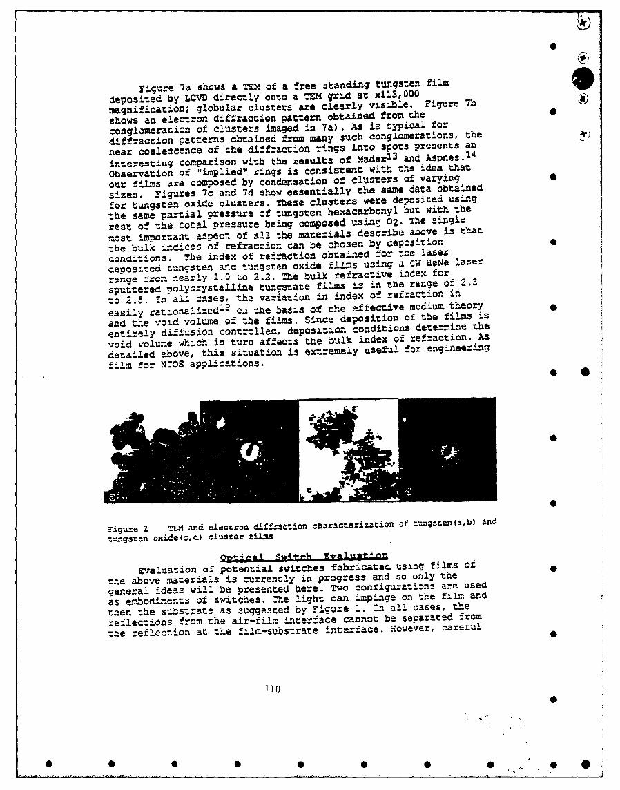
0
Figure 7a shows a TEM of a free standing tungster film
deposited by LCVD directly onto a TEM grid at x113,000magnification; globular clusters are clearly visible. Figure 7b
shows an electron diffraction pattern obtained from theconglomeration of clusters imaged in 7a). As iz typical for
diffraction patterns obtained from many such conglomerations, the
near coalescence of the diffraction rings into spots presents an
interesting comparzlSon with the results of Mader 1 3 and Aspnes. 1 4
Observation of "implied" rings is consistent with the idea that
our films are composed by condensation of clusters of varying
sizes. FigTres 7c and 7d show essentially the same data obtained
for tungsten oxide clusters. These clusters were deposited using
the same partial pressure of t=gsten hexacarbolyl but with the
rest of the total pressure being composed using 02. The single
most ipor:ant aspect of all the materials describe above is ttat
the bulk indices of refraction can be ciosen by depositionf
conditions. The index of refraction obtained for the laser
Qeoosited tungsten and t-angsten oxide films using a CW HeNe laser
range frcm nearly 1.0 to 2.2. The bulk refractive index for
sputtered polycrystalline tungstate films is in the range of 2.3
to 2.5. In all cases, the variation in index of refraction in
easily rationalized' 3 ca the basis of the effective medium theory
and the void volume of the films. Since deposition of the films is
entirely diffusion controlled, deposition conditions determine the
void volume which in turn affects the bulk index of refraction.
detailed above, this situation is extremely useful for engineering
film for N:OS applications. * 0
C0
Figue 2 TVM and electron diffac:ion characterization of :,=gseen(a,b) and
=gs3ten oxide(c,d) cluster fzs
Evaluauion of potential switches fabricated using films of
the above materia1s is current-ly in progress and so only the
general ideas will be presented here. Two confiurations are used
as embodieiets of switches. The light can impinge on the film and
then the substrate as suggested by Figuze 1. In all cases, the
re-flecions from the air-f-lm interface cannot be separated from"the .e2..ec-ion at the film-substrate interface. iowever, careful
]]0
• • • •• • , •,1•0
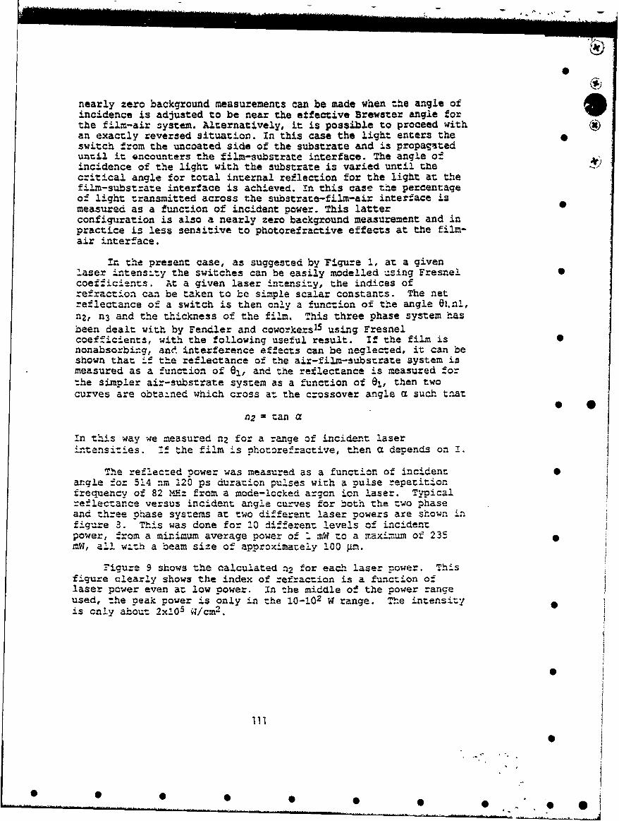
nearly zero background measurements can be made when the angle ofincidence is adjusted to be near the etfective Brewster angle forthe film-air system. Alternatively, it is possible to proceed withan exactly reversed situation. In this case the light enters the 0switch from the uncoated side of the substrate and is propagateduntil it encounters the film-substrate interface. The angle ofincidence of the light with the substrate is varied until tXecritical angle for total internal reflection for the light at thefilm-substrate interface is achieved. in this case the percentageof light transmitted across the substrate-film-air interface ismeasured as a func:ion of incident power. This latterconfiguration is also a nearly zero background measurement and inpractice is less sensitive to photorefractive effects at the film-air interface.
in the present case, as suggested by Figure 1, at a givenlaser in.tens:ry the switches can be easily modelled using Fresne! 0coefficients. At a given laser intensity, the indices ofrefraction can be taken to be simple scalar constants. The netreflectance of a switch is then only a function of the angle Oi.n!,nZ, n3 and the thIckness of the film. This three phase system hasbeen dealt with by Fendler and coworkers1 5 using Fresnelcoefficients, with the following useful result. If the film is 0nonabsorbing, and interference effects can be neglected, it can beshown that if the reflectance of the air-film-substrate system ismeasured as a function of 0I, and the reflectance is measured forthe simpler air-substrate system as a function of 81, then twocurves are obtained which cross a: the crossover angle a such trat
n2 = tan a
In this way we measured n2 for a range of incident laseri-.tensities. _ the film is Photorefractive, then a depends on I.
The reflected power was measured as a function of incidentangle for 514 nm 120 ps duration pulses with a pulse repetitionfrequency of 82 MHz from a mode-locked argon ion laser. Typicalreflectance versus incident angle curves for both the two phaseand three phase systems at two different laser powers are shown infigure 3. This was done for 10 different levels of incidentpower, from a minimum average power of 1 mW to a maaximum of 235mW, all w&th a beam size of approximately 100 Pm.
Figure 9 shows the calculated a2 for each laser mower. Thisfigure clearly shows the index of refraction is a function oflaser power even a; low power. In the middle of the power rangeused, the peak power is only in the 10-102 W range. The intensityis only about 2x10⁵ W/cm2 .
Ill
111
S• • •"O •
*X Misurate 4'!ii 2=5 AW 43iliia I &V &3ibetmg I
* 0.08S0.07
I1 0.06a 0.050a 0.04t 0.03" 0.02.." 0.01
S 0* 20 30 40 so 60 70 80 0
"g511c oa umia e (d4qeileF!•gi:e 8. Reflectance from a tungsten oxide cJluster film as a function of
angle of incidence and incident power.
1.82 T'
1.781
u2 1.76 -- .1.74 T
1.72
1.7 .
50 100 150 200 250
"is dant Pow=z [~IFigure 9. :ndex of :of:action as a !unction of incident power f-d "i-m-subs:rate c-o03over angle data.
Now cham a nonlinear effect has been detected, the next step 0is to determine the time scale of the nonlinearity at differentwavelengths. This will be accomplished by using a "pump" pulse toinitiate the nonlinearity, then following the "pump" pulse with aprcbe pulse to investigate the changes in the film due to the"pump" pulse. We plan to examine the nonlinear response using oursingle shot to kHz pulse selection capability. To examine the 0source and order of the nonlinearity we can measure in greaterpreci-sion and detail the power dependence of n2. The high speedlaser facility at Rome Laboratory has a system capable of 0.6 fsresolution in the pump-probe delay, and a femtosecond pulsecapability of < 100 fs at 620 nm and fram 700-900 nm. It also h-sa < 10 ps capability from 200-1100 nr. 0
112
0
0, * S 0 0 0 0 0 ." 0 0

0
These measurements will be the starting point for completespectral, spatial, temporal and switching energy evaluation ofNTOS devices. Considering that we are only in the earliest stages •of materials development, the admittedly preliminary results areextremely encouraging.
Optical switches based on nonlinear interfaces haveconsiderable promise towards meeting the myriad of design criteria 0for producing devices relevant to digital optical computingapplications. Novel materials which can only be synthesized usinglaser chemistry of organometallics have a number of uniqueadvantages for the design and fabrication of such switches. Xnagreement with theoretical predictions metal oxide cluster filmswould seem to be highly photorefractive. 9
We gratefully acknowledge that this research was supported byRome Laboratory, Syracuse University and by the Donors to the?etuoleum Research Fund as Administered by the American ChemicalSociety 0
1 P. W. Smith, W. J. Tomilnson, P. J. Maloney, J. P. Hemann, ZEE= J.Quant. Elec., OR-17, 340-347(1981) and references therein
2 Nicholas C. Craft, M. E. Prise, Zaser Focus World, May 1990 pp. 191-200and references therein. see also H. Danann and K. Gortler, Opt. •Commun., 3, 312(19-1)
3 D. R. Andersen and a. J. Regan, J. Opt. So*. Am. A, 6, 1484 (1989) andreferences therein
4 R. Cuykendall and D. R. Andersen, Opt. Commun., 62, 232 (1987)5 D.- . AsPnOs, FEXE J. Quant. E=ec., 25, 1056-1063(1989)6 S. Henon, J. Meunier, Rev. Sci. Instrum., 62, 936-939(1991) 0I see Eicbhi Hanamuza, Phys. Rev. a., 37, 1273-1279(1988-1:)8 A. E. Neeves, M. H. Biznboim, Opr. Lect., 13, 1087-1089("988)9 .H. Chew, M. Kerker, J. Opt. Sci. Am. B., 2, !02S-1027(1985), M. Kerker,
3. Collooid and nt~erface Sca., 118, 417-421(1987), 4. Ke:ker, J. Opt.Sci. .•m. a., 2, 1327-!329(:985), Das, P., Metiu, H., J. Phys. C.2em.,89, 4680-4687 (1985).
10 for an overview of LC=D see for example D. Bauerle, "Chem.cal ProcessingWith Lasers', Springer Series in Materials Science, Vol.I(Springer,Berlin, 1986) and for a diagram of our simple LC0D apparatus Zee DanRooney, D. Negro~ti, T. Byassee, D. Macero, B. Vastag and J. Chaiken,J7. Zlecrochsm. Soc., 137, pp. 1162-1166(!990), see also J. Chaiken, USPatent 4,971,853
11 Casey, H.J., Villarica, M., and C.haiken, J., J. Phys. Chem., in press,Apr 92.
12 Casey, M. J., Chaiken, J., in preparation13 S. Mader, Thin Solid Films, 2, 35-41(1964), S. Mader, H. Wid.er, 2t. N.
d'Heurle and A. $. Nowick, Appl. Phys. LZet., 3, 201(1963)14 D. E. Aspnes, Thin Solid Films, 89, pp. 249-202(1982)I1 Zhao, X., Herve, P., Fendler, T., J. Phys. Chem., 93, 908-916(1989)
113
X)
MISSION
OF
ROME LABORATORY
Rome Laboratory plans and executes an interdisciplinary program in re-
search, development, test, and technology transition in support of Air
Force Command, Control, Communications and Intelligence (C31) activities
for all Air Force platforms. It also executes selected acquisition programs
in several areas of expertise. Technical and engineering support within
areas of competence is provided to ESD Program Offices (POs) and other
ESD elements to perform effective acquisition Ct; C31 systems. In addition,
Rome Laboratory's technology supports other AFSC Product Divisions, the
Air Force user community, and other DOD and non-DOD agencies. Rome
Laboratory maintains technical competence and research programs in areas
including, but not limited to, communications, command and control, battle
management, intelligence information processing, computational sciences
and software producibility, wide area surveillance/sensors, signal proces-
sing, solid state sciences, )hotonics, electromagnetic technology, super-
conductivity, and electronic reliability/maintainability and testability.
• • • •• • •