Embed Size (px)
Citation preview
1
1
TO BE REALLYSURE
WWW.VAF.NL
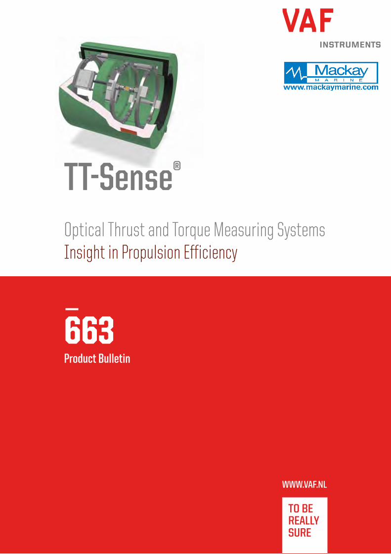
663Product Bulletin
TT-Sense®
Optical Thrust and Torque Measuring SystemsInsight in Propulsion Efficiency

Introduction
Since 1938 VAF Instruments is an established name in the world of marine measuring
equipment. The need for increased energy performance and necessity to comply to rules
and regulations, inspired us to develop the next step in our successful line of sensors:
the TT-Sense®. The use of a TT-Sense® means getting more insight in your propeller
efficiency, hull resistance and vessel trim optimization. Managing propeller thrust and
hull resistance at full scale enable savings up to 20% and in some cases even more. This
real thrust measurement is performed by highly accurate optical sensor technology.
Why a thrust and torque measuring system? Thrust measurement provides you with precise information on propulsion efficiency
related to consumed energy. By giving instantaneous read-out of real thrust, torque,
speed and power, the effects of operational changes can be monitored. When these
effects are visible, you can use your propulsion system in the most efficient way. This will
considerably reduce your fuel costs, and beside that it will indicate malfunctions in the
propulsion system as early as possible, both being primary cost drivers.
Where is the TT-Sense® thrust and torque measuring system used? TT-Sense® thrust and torque measuring systems can be used for propulsion installations
of all kind. For example for continuous measurement of propeller efficiency or continuous
power measurement, as well as continuous trending of thrust, torque, shaft speed
and power. Giving direct visual control of changes in resistance or performance due to
trimming and hull and propeller fouling of the vessel.
System output The standard output of the TT-Sense® thrust and torque measuring system consists of a
thrust, torque, shaft speed and power signal. The system can be extended with VAF fuel
consumption Flowmeters, speedlog/GPS input and a range of nautical and navigational data.
Advantages Due to a robust design, TT-Sense® thrust and torque measuring systems have a high
durability and are able to withstand the typical harsh environmental conditions onboard
ships, dredgers and in engine rooms, etc. Innovative optical sensor technology results in
a high accuracy. TT-Sense® thrust and torque measuring systems are maintenance free as
a result of non-contact power and signal transmission.
Principle of operation
The TT-Sense® thrust and torque measuring system can be mounted on intermediate
shafts after the thrust bearing. When a shaft is subject to thrust and torque this results
in a small strain at the shaft surface.
LEDs and extremely accurate optical sensors can detect these small displacements,
in both axial and radial directions. The measured values are transferred continuously
from the rotating shaft to the stator part through wireless data connection. Power
transmission from the stator to the rotating shaft is performed by means of induction.
The stator part consists of a power transmission coil, a data signal receiver and a control
box equipped with digital or analogue output connections. These outputs can be linked
directly to the vessels data network, monitoring- or control system.
Mounting ringPower transmission foil
Torque
∆x
LED armDetecter arm
∆y
Thrust
Sectional view
∆y and ∆x are small movements of the propeller shaft surface due to strain.
∆y is the movement in torque direction and ∆x is the movement
in thrust direction.
Optical displacement measurement
Detector
zy
x

3
3
LED armDetecter arm
Typical system arrangement
Fault detection
SPU3
Speed log/GPS 12x PT2 Flowmeter(flow + temp)For max. 6 consumers
TT-Sense®
Typical TT-Sense® thrust and torque measuring system with optional fuel consumption measurement
Ships monitoring

Applications of thrust and torque measurement
By using the TT-Sense® propeller thrust measuring possibilities, the
performance of the propeller and hull can be measured separately
providing an important input to fuel saving and maintenance
investment decisions. Customers have reported savings of up to 20%
on fuel and maintenance costs by managing propeller performance
and hull resistance at full scale.
In combination with a monitoring or management system, such
as VAF Instruments PEM2, PEM4 or IVY®, the TT-Sense® measuring
system can be used in a variety of applications.
The benefits of measuring torque:
- Determines the total ship resistance change over time.
- Provides insight into engine performance related to
consumed fuel.
- Enables optimisation of the efficiency of engine-driven
installations to reduce fuel costs.
- Visualisation of engine load margin. Avoiding engine overload.
- Monitoring of torque, speed, power and, when combined with
Flowmeters, fuel consumption.
- Direct visual control of the effects of operational changes.
- Torsional vibration analysis for frequencies up to 50 Hz.
The benefits of measuring propeller thrust in addition to torque:
- Enables optimisation of ship’s propulsion performance.
- Provides detailed insight in separated performance of
propeller and hull.
- Determines the proper individual timing for a hull or
propeller cleaning based on the actual hull resistance or
propeller performance.
- Direct detailed visualisation of the effects of
operational changes.
- Measures hull cleaning and/or new hull coating effects on
the ship’s resistance.
- Measures propeller cleaning and/or repair effects.
- Determines the optimal settings for propeller efficiency at
actual conditions for a controllable pitch propeller.
- Measures new propeller designs, and/or hull designs or
modifications (like for instance a new bulbous bow design).
- Measures the effect of Energy Saving Devices
- Detects cavitation.
- Prevents from negative thrust during deceleration, thus
avoiding energy waste.
- Continuous, long term trending and analysis of detailed
propulsion KPIs.
- Beneficial to compliance with ISO 14001 and/or ISO 19030
Energy conversions & efficiencies
Only by measuring propeller thrust you are able to separate the propeller efficiency from the hull resistance
FUEL >
FUEL >
FUEL >
> SHIP SPEED
> SHIP SPEED
> SHIP SPEED> THRUST >
> TORQUE >
> TORQUE >
ENGINE + PROPELLER + SHIP HULL
PROPELLER + SHIP HULLENGINE
ENGINE PROPELLER SHIP HULL
PROPELLER FUEL HULL EFFICIENCY EFFICIENCY EFFICIENCY
‘S
‘S
‘S
fuel speedthrust torque hull resistance

Monitoring and management solutions
The TT-Sense® thrust and torque measuring system can be combined with the PEM4 Propulsion Efficiency Monitor, the vessel’s monitoring
system and/or IVY® propulsion performance management solution to use TT-Sense® to its full potential.
PEM4 Propulsion Efficiency Monitor
The PEM4 instantly shows thrust, torque, speed, shaft power, propeller performance and other
selected measuring data. Additional Flowmeter signals and temperature sensor signals enable
calculation of the engines fuel consumption including temperature compensation. In combination
with input signals from speedlog or GPS, the PEM4 will display the specific fuel consumption per kW
and/or per nautical mile.
IVY® Propulsion Performance Management Solution
IVY®, VAF Instruments’ solution for Propulsion Performance
Management, brings you the fleet at your fingertips.
From ship to shore, IVY® enriches big data for powerful
analysis. The web application of IVY® provides fleet and ship
performance visualisation and insight into the relevant data
and more than 30 KPIs. IVY® can be combined with a range of
sensors on board, including TT-Sense®. IVY® brings Big Data
back to the essence.
PEM2 Touch screenFor monitoring TT-Sense® thrust, torque, shaft speed and power output only, we supply the PEM2 touch screen as a standalone unit.
PEM2 PEM4 IVY®
User interface Touch screen
on ship
Touch screen
on ship
Web application on any device
Visualisation of torque, shaft rpm, power, thrust and propeller quotient x x x
Fuel consumption, SFOC, FOC - x x
Ship speed (STW / SOG) - x x
Zoom in on individual sensor signals - x x
Visualisation of KPIs 4 7 > 30
Data enrichment - - x
Hull resistance (over time) - - x
Propeller performance (over time) - - x
Quantified additional FOC in $ due to performance decrease - - x
Integrated voyage reporting (eg. MRV) - - x
Ship locations, track and heading - - x
Compare sensor data - - x
Compare ship’s KPIs / sensor data - - x
Fleet overview and performace - - x
Below table is a concise overview of the functionality of the various system solutions. For detailed information about each solution, we refer to
the specific documentation.
5
TT-Sense®
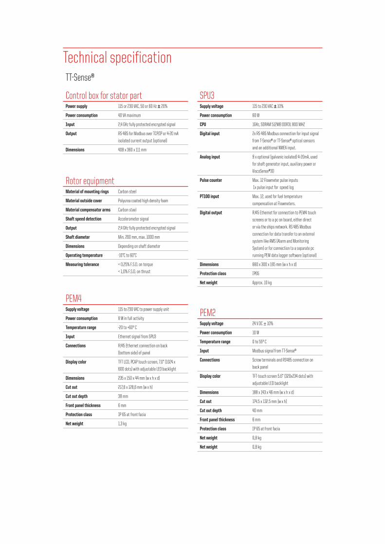
Control box for stator partPower supply 115 or 230 VAC, 50 or 60 Hz ± 20%
Power consumption 40 VA maximum
Input 2,4 GHz fully protected encrypted signal
Output RS 485 for Modbus over TCP/IP or 4-20 mA
isolated current output (optional)
Dimensions 408 x 360 x 111 mm
Rotor equipmentMaterial of mounting rings Carbon steel
Material outside cover Polyurea coated high density foam
Material compensator arms Carbon steel
Shaft speed detection Accelerometer signal
Output 2,4 GHz fully protected encrypted signal
Shaft diameter Min. 200 mm, max. 1000 mm
Dimensions Depending on shaft diameter
Operating temperature -10°C to 60°C
Measuring tolerance < 0,25% F.S.D. on torque
< 1,0% F.S.D. on thrust
PEM4Supply voltage 115 to 230 VAC to power supply unit
Power consumption 8 W in full activity
Temperature range -20 to +60º C
Input Ethernet signal from SPU3
Connections RJ45 Ethernet connection on back
(bottom side) of panel
Display color TFT LCD, PCAP touch screen, 7.0” (1024 x
600 dots) with adjustable LED backlight
Dimensions 235 x 150 x 44 mm (w x h x d)
Cut out 217,6 x 128,6 mm (w x h)
Cut out depth 38 mm
Front panel thickness 6 mm
Protection class IP 65 at front facia
Net weight 1,3 kg
SPU3 Supply voltage 115 to 230 VAC ± 10%
Power consumption 60 W
CPU 1GHz, SDRAM 512MB DDR3L 800 MHZ
Digital input 2x RS 485 Modbus connection for input signal
from T-Sense® or TT-Sense® optical sensors
and an additional NMEA input.
Analog input 9 x optional (galvanic isolated) 4-20mA, used
for shaft generator input, auxiliary power or
ViscoSense®3D
Pulse counter Max. 12 Flowmeter pulse inputs
1x pulse input for speed log
PT100 input Max. 12, used for fuel temperature
compensation at Flowmeters.
Digital output RJ45 Ethernet for connection to PEM4 touch
screens or to a pc on board, either direct
or via the ships network. RS 485 Modbus
connection for data transfer to an external
system like AMS (Alarm and Monitoring
System) or for connection to a separate pc
running PEM data logger software (optional)
Dimensions 660 x 300 x 165 mm (w x h x d)
Protection class IP65
Net weight Approx. 10 kg
PEM2Supply voltage 24 V DC ± 10%
Power consumption 10 W
Temperature range 0 to 55º C
Input Modbus signal from TT-Sense®
Connections Screw terminals and RS485 connection on
back panel
Display color TFT-touch screen 5.6” (320x234 dots) with
adjustable LED backlight
Dimensions 188 x 143 x 46 mm (w x h x d)
Cut out 174.5 x 132.5 mm (w x h)
Cut out depth 40 mm
Front panel thickness 6 mm
Protection class IP 65 at front facia
Net weight 0,8 kg
Net weight 0,8 kg
Technical specification
7
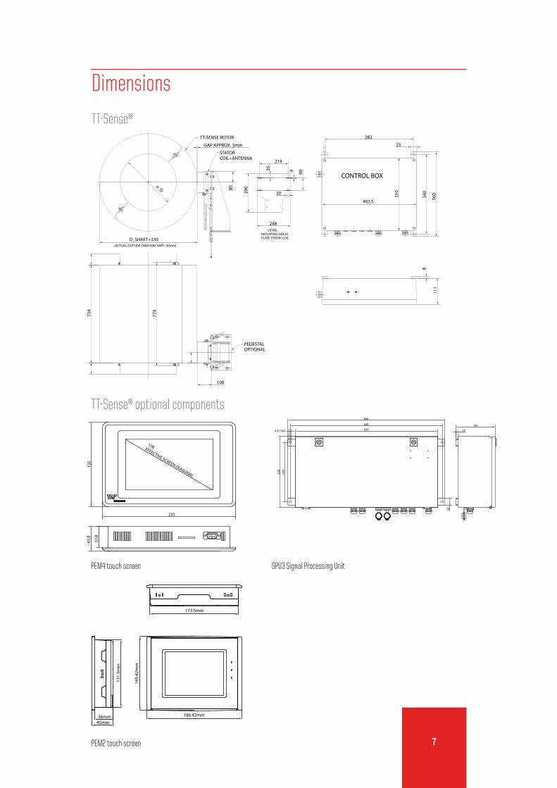
Dimensions
TT-Sense®
SPU3 Signal Processing Unit
PEM2 touch screen
165
10
640
660
250
300
n 8,7(4x)
30
600
186.42mm
145.
42m
m
173.5mm
36mm45mm
131.
5mm
cut out
174.5±0.5
132.
5mm
±0.5
PEM4 touch screen
178EFFECTIVE SCREEN DIAGONAL
150
235
37,8
43,9
TT-Sense® optional components
CONTROL BOX
STATORCOIL+ANTENNA
PEDESTALOPTIONAL
DETAILMOUNTING HOLESPLATE STATOR COIL
(ACTUAL OUTSIDE DIAM MAY VARY -30mm)
402,5
310
360
25
382
340
111
8
774
734
D_SHAFT+330
GAP APPROX. 3mm
80248
214
20
935
90
290
108
n D
TT-SENSE ROTOR

1
Quotation and ordering information1. Number of units:
2. Available shaft length [mm]:
3. Ship’s name / hull:
4. Please provide shaft line drawing for information:
õ new building õ retrofitting
5. Design conditions:
power [kW]: thrust [kN]:
speed [rpm]:
shaft material: shear modulus G [N/mm2]: young’s modulus E [N/mm2]:
shaft diameter (+tolerance) [mm]: (min 200 mm)
inside (bore) diameter [mm]:
duty õ propeller shaft õ other:
6. System:
required output thrust õ RS 485/Modbus
õ range 4 - 20 mA = kN
torque õ RS 485/Modbus
õ range 4 - 20 mA = kNm
speed õ RS 485/Modbus
õ range 4 - 20 mA = rpm
power õ RS 485/Modbus
õ range 4 - 20 mA = kW
õ other:
options õ Propulsion Performance Management by IVY®
õ PEM4 for Fuel Consumption Measurement, thrust, torque, shaft speed and power read-out
õ touch screen display (PEM2) for thrust, torque, shaft speed and power read-out
All c
opyr
ight
s res
erve
d PB-
663-
GB-0
517 S
uper
sede
s PB-
663-
GB-0
217
VAF Instruments B.V.
Vierlinghstraat 24, 3316 EL Dordrecht, The Netherlands
P.O. Box 40, 3300 AA Dordrecht, The Netherlands
T +31 (0) 78 618 3100, [email protected]
Specifications subject to change without notice.
Agents and distributors in more than 50 countries.
Name:
Place and date:
For further information see relevant Product Bulletins
or www.vaf.nl
Represented by