Embed Size (px)
Citation preview

Optical/Electrical Components
Needed for iKAGRA IMC Servo
Yuta Michimura Ando Group
Department of Physics, University of Tokyo
Aug 4, 2014

• Start discussion on listing up what we need for iKAGRA IMC
(and PSL) servo
• Focus mainly on optical and electrical components
• References:
- JGW-T1402349 (iKAGRA PMC study)
- JGW-G1402302 (FSS modeling)
- JGW-G1402520 (GWADW2014 IOO poster by Nakano)
- JGW-D1402507 (IOO 3D drawing)
- JGW-T1302068 (layout around IMMT)
- JGW-D1402492 (IMC suspension cabling)
- JGW-D1402516 (anchor, floor mortar, floor cutting lines)
- Wiki/SmallOptics (list of small optics)
- Wiki/OutputTables (list of output optical tables)
Scope
2

Optical Configuration
3
NPRO
2W FI EOM EOM EOM EOM
temp PZT
PZT
pico
pico
PZT
IFI
pico
pico
pico
pico for MIF
MCe
MCo MCi
STM1
STM2
IMMT1
IMMT2
OSEM OSEM
OSEM
f_PMC
51.75MHz
(QND lab)
f_1
39.39MHz
(Ando lab)
f_IMC
15MHz
(Mio lab)
wideband
(Somiya lab)
Faraday
(Ando lab)
PSL table
periscope PMCREFL
(DC,RF)
PMCTRANS
(DC)
IMCTRANS
(DC,QPD)
IMCREFL
(DC, RF,QPD)
ISS1
(DC)
ISS2
(DC,QPD)
REFL
(DC,RF,QPD)
oplev
oplev
oplev
pico pico
pico
current
FRC
AO
M

Suspension Local Damping
4
NPRO
2W FI EOM
temp PZT
PZT
pico
pico
PZT
IFI
pico
pico
pico
pico for MIF
MCe
MCo MCi
STM1
STM2
IMMT1
IMMT2
OSEM OSEM
OSEM
f_PMC
51.75MHz
(QND lab)
Faraday
(Ando lab)
PSL table
periscope
oplev
oplev
oplev
digital system
coil drivers (12)
(4 for each mirror)
pico pico
pico
picomotor driver (6)
(2 for each mirror)
current
EOM EOM EOM
f_1
39.39MHz
(Ando lab)
f_IMC
15MHz
(Mio lab)
wideband
(Somiya lab) PMCREFL
(DC,RF)
PMCTRANS
(DC)
IMCTRANS
(DC,QPD)
IMCREFL
(DC, RF,QPD)
ISS1
(DC)
ISS2
(DC,QPD)
REFL
(DC,RF,QPD)
FRC
AO
M
Initial Alignment
5
NPRO
2W FI EOM
temp PZT
PZT
pico
pico
PZT
IFI
pico
pico
pico
pico for MIF
MCe
MCo MCi
STM1
STM2
IMMT1
IMMT2
OSEM OSEM
OSEM
f_PMC
51.75MHz
(QND lab)
Faraday
(Ando lab)
PSL table
periscope
oplev
oplev
oplev
pico pico
pico
digital system picomotor driver (12)
(2 for each mirror)
current
EOM EOM EOM
f_1
39.39MHz
(Ando lab)
f_IMC
15MHz
(Mio lab)
wideband
(Somiya lab) PMCREFL
(DC,RF)
PMCTRANS
(DC)
IMCTRANS
(DC,QPD)
IMCREFL
(DC, RF,QPD)
ISS1
(DC)
ISS2
(DC,QPD)
REFL
(DC,RF,QPD)
FRC
AO
M

PMCREFL
(DC,RF)
PMCTRANS
(DC)
IMCTRANS
(DC,QPD)
IMCREFL
(DC, RF,QPD)
ISS1
(DC)
ISS2
(DC,QPD)
REFL
(DC,RF,QPD)
Intensity Stabilization
6
NPRO
2W FI EOM
temp PZT
PZT
pico
pico
PZT
IFI
pico
pico
pico
pico for MIF
MCe
MCo MCi
STM1
STM2
IMMT1
IMMT2
OSEM OSEM
OSEM
f_PMC
51.75MHz
(QND lab)
Faraday
(Ando lab)
PSL table
periscope
oplev
oplev
oplev
pico pico
pico
digital system
current
ISS servo board
binary output(BO)
EOM EOM EOM
f_1
39.39MHz
(Ando lab)
f_IMC
15MHz
(Mio lab)
wideband
(Somiya lab)
ISS is not a default plan in iKAGRA
FRC
AO
M

PMC Servo
7
NPRO
2W FI EOM
temp PZT
PZT
pico
pico
PZT
IFI
pico
pico
pico
pico for MIF
MCe
MCo MCi
STM1
STM2
IMMT1
IMMT2
OSEM OSEM
OSEM
f_PMC
51.75MHz
(QND lab)
Faraday
(Ando lab)
PSL table
periscope
oplev
oplev
oplev
pico pico
pico
current
digital system
PMC servo board
~ 51.75MHz IQ dmd
PZT driver (1)
binary output(BO)
EOM EOM EOM
f_1
39.39MHz
(Ando lab)
f_IMC
15MHz
(Mio lab)
wideband
(Somiya lab) PMCREFL
(DC,RF)
PMCTRANS
(DC)
IMCTRANS
(DC,QPD)
IMCREFL
(DC, RF,QPD)
ISS1
(DC)
ISS2
(DC,QPD)
REFL
(DC,RF,QPD)
FRC
AO
M

Frequency Stabilization
8
NPRO
2W FI EOM
temp PZT
PZT
pico
pico
PZT
IFI
pico
pico
pico
pico for MIF
MCe
MCo MCi
STM1
STM2
IMMT1
IMMT2
OSEM OSEM
OSEM
f_PMC
51.75MHz
(QND lab)
Faraday
(Ando lab)
PSL table
periscope
oplev
oplev
oplev
pico pico
pico
current
digital system
coil drivers (12)
(4 for each mirror)
~ 15MHz IQ dmd
FSS servo board
IMC servo board
binary output
(BO)
PZT driver (1)
EOM EOM EOM
f_1
39.39MHz
(Ando lab)
f_IMC
15MHz
(Mio lab)
wideband
(Somiya lab)
HV amp
PMCREFL
(DC,RF)
IMCTRANS
(DC,QPD)
IMCREFL
(DC, RF,QPD)
ISS1
(DC)
ISS2
(DC,QPD)
REFL
(DC,RF,QPD)
FRC
AO
M
AOM driver
PMCTRANS
(DC)

Alignment Sensing and Control
9
NPRO
2W FI EOM
temp PZT
PZT
pico
pico
PZT
IFI
pico
pico
pico
pico for MIF
MCe
MCo MCi
STM1
STM2
IMMT1
IMMT2
OSEM OSEM
OSEM
f_PMC
51.75MHz
(QND lab)
Faraday
(Ando lab)
PSL table
periscope
oplev
oplev
oplev
pico pico
pico
current
digital system
coil drivers (12)
(4 for each mirror)
~ 15MHz IQ dmd
PZT driver (2)
EOM EOM EOM
f_1
39.39MHz
(Ando lab)
f_IMC
15MHz
(Mio lab)
wideband
(Somiya lab) PMCREFL
(DC,RF)
PMCTRANS
(DC)
IMCTRANS
(DC,QPD)
IMCREFL
(DC, RF,QPD)
ISS1
(DC)
ISS2
(DC,QPD)
REFL
(DC,RF,QPD)
FRC
AO
M

Cameras
10
NPRO
2W FI EOM
temp PZT
PZT
pico
pico
PZT
IFI
pico
pico
pico
pico for MIF
MCe
MCo MCi
STM1
STM2
IMMT1
IMMT2
OSEM OSEM
OSEM
f_PMC
51.75MHz
(QND lab)
Faraday
(Ando lab)
PSL table
periscope
oplev
oplev
oplev
pico pico
pico
current
digital system
PMCTRANS
MCeF
IFIF
PMCREFL
IMCREFL
6 cameras?
How do we put their signals in the digital system?
IMCTRANS
EOM EOM EOM
f_1
39.39MHz
(Ando lab)
f_IMC
15MHz
(Mio lab)
wideband
(Somiya lab) PMCREFL
(DC,RF)
PMCTRANS
(DC)
IMCTRANS
(DC,QPD)
IMCREFL
(DC, RF,QPD)
ISS1
(DC)
ISS2
(DC,QPD)
REFL
(DC,RF,QPD)
FRC
AO
M

• We need two QPDs for each port we want to monitor the
beam alignment
• It would be nice to have standardized Gouy phase
telescopes for each port
• Below is an example aLIGO
one (~ 15 cm x 55 cm)
LIGO-T1000247
Gouy Phase Telescopes
11

• PSL periscope
- we have dumped rods available in Ando Lab
Newport 45
Newport M-340-RC already delivered to Ohshima-san
• Gouy phase telescopes and other optical components for
each port
- we can buy flat mirrors and mounts with a rough
estimate of numbers, but what do we do for lenses?
• High voltage amplifier for broadband EOM
Newport 3211 (0.5 MHz bandwidth)
already included in TTFSS servo board
• AOM for FRC?
was already there at ICRR (including a driver)
• I suppose there are much more……
Optical Components Missing
12

• IMC servo (2 MHz/rtHz @ 0.1 Hz, 0.1 Hz/rtHz @ 10 Hz)
- AOM (common mode board; DC – 100 kHz)
efficiency: 5.3 MHz/V, range: 90-130 MHz
- MCe (digital system; DC – 1 Hz; optional)
• FRC servo (with rough estimate, 170 Hz/rtHz @ 1kHz)
- laser temp (digital system; DC – 0.1 Hz)
efficiency: 3 GHz/V, range: 30 GHz
- laser PZT (FSS board; DC – 1 kHz)
efficiency: 1 MHz/V, range: 100 MHz
- EOM (FSS board; 1 kHz – 1 MHz)
efficiency: 0.01 * (f/1 Hz) Hz/V, range: 0.6 MHz
FSS Topology (rough idea)
13
Actuation efficiency and range?
Numbers to remember:
- Kamioka seismic noise 2e-7 m/rtHz @ 0.1 Hz, 1e-11 m/rtHz @ 10 Hz, 1e-13 m/rtHz @ 100 Hz
- IMC suspension vibration isolation ratio: 0 dB @ 0.1 Hz, -60 dB @ 10 Hz, -140 dB @ 100 Hz
- IMC round-trip length: 2*26.65 m
- laser frequency: 2.8e14 Hz
- NPRO free-run frequency noise: 10 kHz/f Hz/rtHz
AOM: 3110-197
driver: 1110AF-AEFO-1.5
(Crystal Technology )
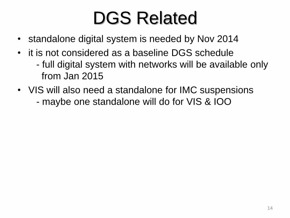
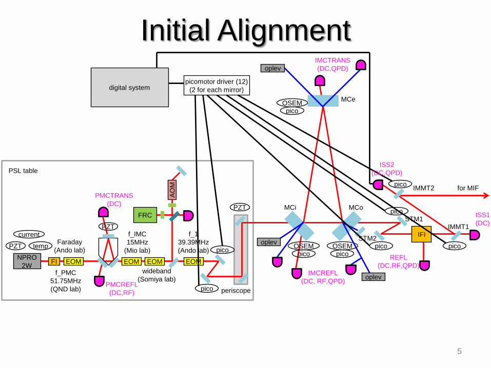
• standalone digital system is needed by Nov 2014
• it is not considered as a baseline DGS schedule
- full digital system with networks will be available only
from Jan 2015
• VIS will also need a standalone for IMC suspensions
- maybe one standalone will do for VIS & IOO
DGS Related
14
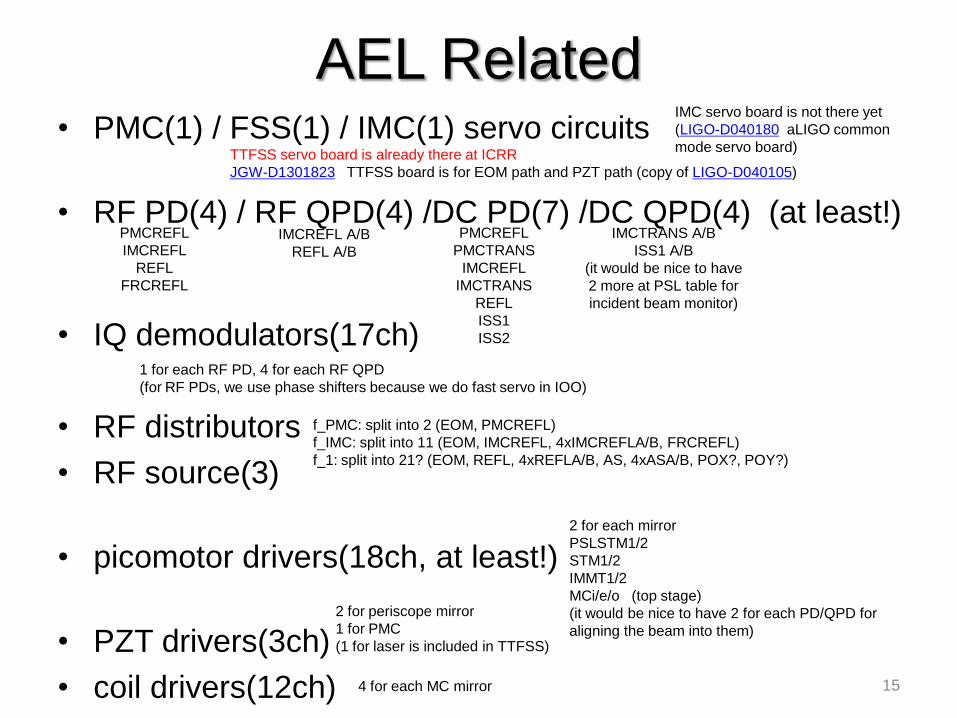
• PMC(1) / FSS(1) / IMC(1) servo circuits
• RF PD(4) / RF QPD(4) /DC PD(7) /DC QPD(4) (at least!)
• IQ demodulators(17ch)
• RF distributors
• RF source(3)
• picomotor drivers(18ch, at least!)
• PZT drivers(3ch)
• coil drivers(12ch)
AEL Related
15
PMCREFL
PMCTRANS
IMCREFL
IMCTRANS
REFL
ISS1
ISS2
IMCTRANS A/B
ISS1 A/B
(it would be nice to have
2 more at PSL table for
incident beam monitor)
TTFSS servo board is already there at ICRR
JGW-D1301823 TTFSS board is for EOM path and PZT path (copy of LIGO-D040105)
PMCREFL
IMCREFL
REFL
FRCREFL
IMCREFL A/B
REFL A/B
1 for each RF PD, 4 for each RF QPD
(for RF PDs, we use phase shifters because we do fast servo in IOO)
f_PMC: split into 2 (EOM, PMCREFL)
f_IMC: split into 11 (EOM, IMCREFL, 4xIMCREFLA/B, FRCREFL)
f_1: split into 21? (EOM, REFL, 4xREFLA/B, AS, 4xASA/B, POX?, POY?)
2 for each mirror
PSLSTM1/2
STM1/2
IMMT1/2
MCi/e/o (top stage)
(it would be nice to have 2 for each PD/QPD for
aligning the beam into them)
2 for periscope mirror
1 for PMC
(1 for laser is included in TTFSS)
4 for each MC mirror
IMC servo board is not there yet
(LIGO-D040180 aLIGO common
mode servo board)

By Schedule (DGS, AEL)
16
Month To Do VIS/AOS IOO
2014/10 install PSL table
2014/11 PMC
FRC
SR560
RF PD x 2, DC PD x 2
TTFSS servo board
RF source x 2 & splitter / mixer
PZT driver x 1ch
2014/12 align beam to IMC
install IMC sus
oplev QPD x 3 picomotor driver x 4 ch
2015/1 digital system installed
IMC LSC
coil drivers x 12ch
picomotor driver x 6 ch
SR560
RF PD, DC PD x 2
RF source x 1 & splitter / mixer
2015/2 IMC ASC RF QPD x 2, DC QPD x 2
IQ demod x 8ch (in fabrication)
RF distributors x 16ch
PZT driver x 1ch
2015/3 improve IMC
install REFL/AS table
PMC servo board
IMC servo board
DC PD x 2, DC QPD x 2
•Blue things are already there (might need modification or soldering)
•Red things are temporary Oplev QPD: JGW-D1402411 (S5981)
• For CLIO, NewFocus drivers below were used
PICOMOTOR EHTERNET CONTROLLER 8752
INTELLIGENT PICOMOTOR DRIVER 8753
Now, they are discontinued and replaced with
Four-Axis Picomotor Controller/Driver Kit 8742-4-KIT
• Picomotor control with EPICS and Python
http://gwwiki.icrr.u-
tokyo.ac.jp/JGWwiki/CLIO/Technicals/PMEPICS
http://gwclio.icrr.u-
tokyo.ac.jp/lcgtsubgroup/digitalsystem/2012/03/new-focus-
picomotor-controlled-at-stda.html
• No special interface circuit is needed for controlling
picomotor from digital system
Picomotor Driver
17
• TBD
• JGW-D1402492 (IMC suspension cabling)
Cables
18

Beams around MCe
19
IMC TRANS
(MCT table)
MCe oplev in
(pylon) MCe oplev out
(pylon)
JGW-D1402507

Beams around MCi and MCo
20
IMC REFL
(IMC REFL table) MCi oplev
in/out
(pylon)
MCe oplev
in/out
(pylon)
dump
dump
dump?
JGW-D1402507

Beams around IMMT1/2
21
JGW-D1402507
ISS2
(pylon->IMMT2 table)
ISS1
(pylon)
REFL
(REFL table)
IFI not included in the drawing yet
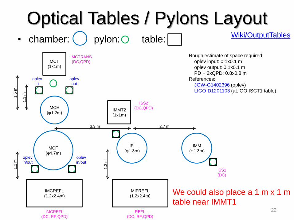
• chamber: pylon: table:
Optical Tables / Pylons Layout
22
MCF
(φ1.7m)
IMCREFL
(1.2x2.4m)
1.2
m
3.3 m
IFI
(φ1.3m)
2.7 m
IMM
(φ1.3m)
1.3
m
MCE
(φ1.2m)
1.1
m
1.5
m
MCT
(1x1m)
MIFREFL
(1.2x2.4m)
IMMT2
(1x1m)
IMCTRANS
(DC,QPD)
ISS1
(DC)
ISS2
(DC,QPD)
IMCREFL
(DC, RF,QPD)
oplev
in
oplev
out
oplev
in/out
oplev
in/out
Rough estimate of space required
oplev input: 0.1x0.1 m
oplev output: 0.1x0.1 m
PD + 2xQPD: 0.8x0.8 m
References:
JGW-G1402396 (oplev)
LIGO-D1201103 (aLIGO ISCT1 table)
Wiki/OutputTables
REFL
(DC, RF,QPD)
We could also place a 1 m x 1 m
table near IMMT1

• port with DC PD + RF PD + 2 x QPD needs at least
periscope, beam shutter, 2 x lens, 4 x mirror, 3 x BS, 4 x beam dump
• optionally
HWP, PBS, CCD, +1 x BS
• some ports needs more
+2 x mirror, +4 x lens
• 2 picomotors/QPD for beam centering
• there are
[before IMMT]
IMCREFL: DC PD + RF PD + 2 x QPD
IMCTRANS: DC PD + 2 x QPD
REFL: DC PD + RF PD + 2 x QPD
ISS1: DC PD
ISS2: DC PD + 2 x QPD
[after IMMT]
AS(SR2): DC PD + RF PD + 2 x QPD
ETMX: DC PD + 2 x QPD
ETMY: DC PD + 2 x QPD
Small Optics for Output Tables
23
Wiki/SmallOptics
LIGO-D1201103 (aLIGO ISCT1 table)
* one grid is 1inch x 1 inch
cf. LIGO-D1201210
(aLIGO ISCT6 table)

• My estimation for iKAGRA is;
• 8 periscope: for adjusting the height
including 2 mirrors (may have to be 2 inch) and a post
mirrors on periscopes are not included in numbers below
• 8 beam shutter: for zeroing the PD offsets and so
• 8 lens (2 inch): for reducing the beam size
• 8-40 lens (1 inch): for Gouy phase telescope, focusing on RF PD
• 16 mirror (2 inch): for steering before reducing the beam size
• 32-48 mirror (1 inch): for steering, folding
• 8 PBS (1inch): for adjusting power
• 24-32 NPBS (1inch): for splitting the beam to PDs, cameras
• 8 HWP (1inch): for adjusting power
• 32 beam dump: for dumping PD reflection
• 8 CCD: for monitoring the beam
• 28 picomotors: for centering the beam on QPDs
Small Optics for Output Tables
24
Wiki/SmallOptics
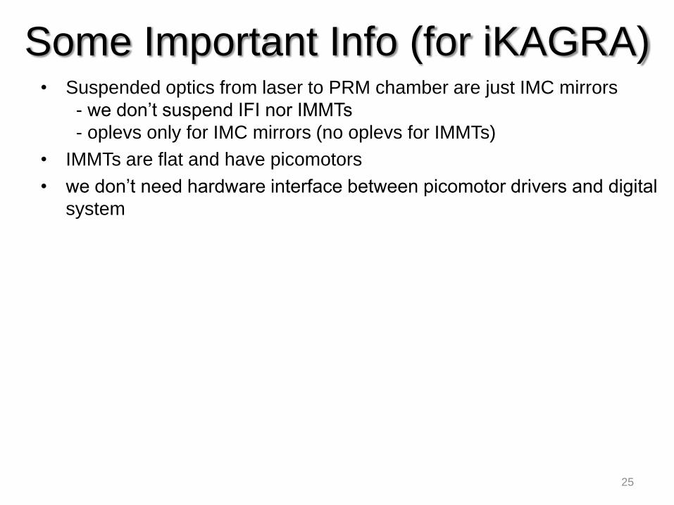
• Suspended optics from laser to PRM chamber are just IMC mirrors
- we don’t suspend IFI nor IMMTs
- oplevs only for IMC mirrors (no oplevs for IMMTs)
• IMMTs are flat and have picomotors
• we don’t need hardware interface between picomotor drivers and digital
system
Some Important Info (for iKAGRA)
25
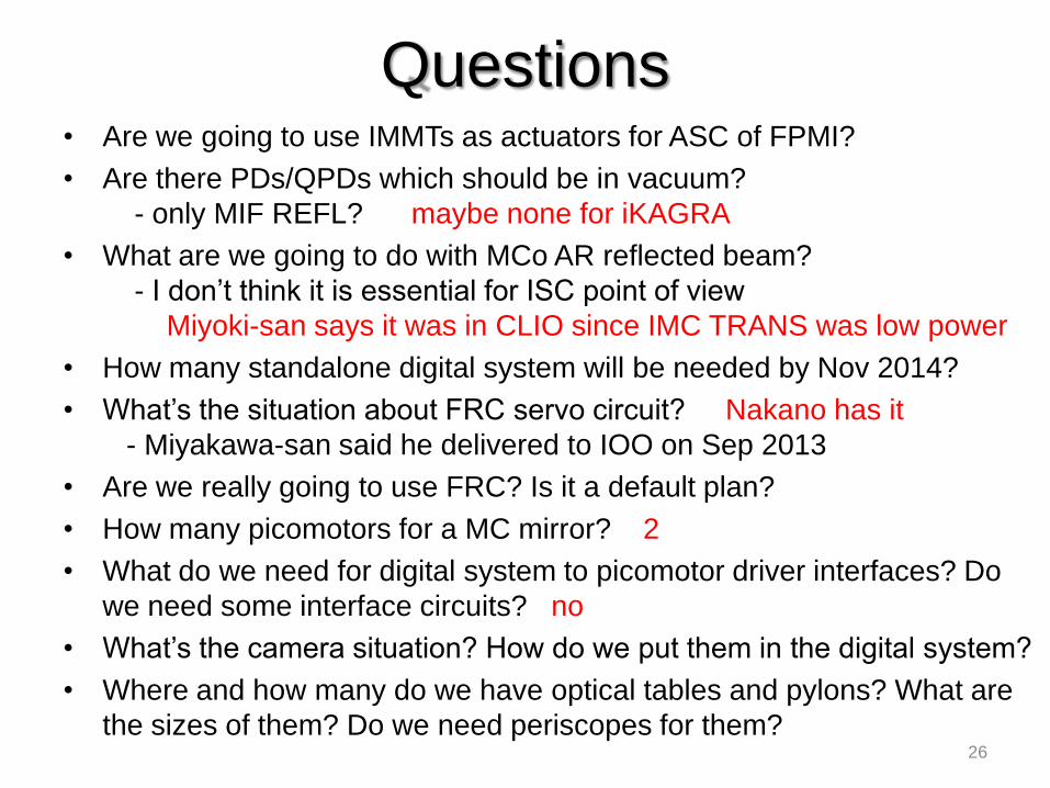
• Are we going to use IMMTs as actuators for ASC of FPMI?
• Are there PDs/QPDs which should be in vacuum?
- only MIF REFL? maybe none for iKAGRA
• What are we going to do with MCo AR reflected beam?
- I don’t think it is essential for ISC point of view
Miyoki-san says it was in CLIO since IMC TRANS was low power
• How many standalone digital system will be needed by Nov 2014?
• What’s the situation about FRC servo circuit? Nakano has it
- Miyakawa-san said he delivered to IOO on Sep 2013
• Are we really going to use FRC? Is it a default plan?
• How many picomotors for a MC mirror? 2
• What do we need for digital system to picomotor driver interfaces? Do
we need some interface circuits? no
• What’s the camera situation? How do we put them in the digital system?
• Where and how many do we have optical tables and pylons? What are
the sizes of them? Do we need periscopes for them?
Questions
26