Embed Size (px)
Citation preview

Optics and Lens Image Optics and Lens Image IntensifierIntensifier
2004.1.92004.1.9 Ashra Meeting @ UHAshra Meeting @ UHAshra-1 Collaboration
Y.Y.AsaokaAsaoka, @ ICRR, @ ICRR

ContentsContents
1. Optical system- Design- Performance
2. Optical Component- R&D status
1. Segment mirrors2. Collector lens3. Lens image intensifier4. Sub-telescope
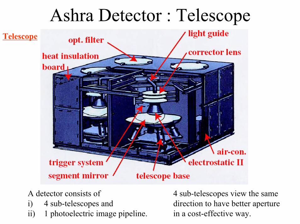
Ashra Detector : TelescopeTelescope
A detector consists of i) 4 sub-telescopes andii) 1 photoelectric image pipeline.
4 sub-telescopes view the same direction to have better aperture in a cost-effective way.

Ashra Detector : Image Pipeline
patent pending
patent pending
Photoelectric Image Pipeline
1. Amplification w/ pipelined I.I.’s2. Self triggering w/ light splitting & phosphor delay
- Signal time scale : ns~µs- Shuttering is important to have higher S/N ratio
3. Fine imaging w/ CMOS sensor
Functions:
Sasaki-san’s Talk
Distinctive features:High precision, high S/N ratio, and self triggering capability

Ashra Optics : Design
• Schmidt-type optics• Spherical segment mirror• Spherical focal surface• 3-element corrector lens
Advantage: a large degree of freedom for optimization of lens surface shape to cancel1. spherical aberration2. chromatic aberration.
pupil : 1m
Modified Baker-Nunn
F/0.74Details can be found inM.Sasaki et al, NIM A492 (2002) 49

Ashra Optics : Performance (1)
NIM A492(2002) 49
wavelength
inci
dent
ang
le
incidentangle
Spot diagram after optimization 4 largest filtered fluorescence peak after propagation in the air

Ashra Optics : Performance (2)
Spot size = 0.0167°(1 arcmin)
using ZEMAX by A.Okumura
NIM A492(2002) 49
incidentangle
from weighted sum of several wavelength
Ashra Optics has a capability to achieve 1 arcmin resolution within the whole FOV of ± 25.

Optical Components
• modification from commercial X-ray II
• UV-transparent acrylic resin
• normal lens• direct cutting w/
or w/o polishing
• Tempax glass• segmented• mold + polish
Material and Method
• spot size < 0.16mmLens I.I.(I.I.= Image Intensifier)
• surface roughness < 20nm• slope accuracy < 1 arcmin
Corrector Lens
• surface roughness < 20nm• spot size < 0.1mm• curvature radius ± 0.1%
Mirror
RequirementsComponents
small sag because of corrector lens (no focusing)
R&D status of each component
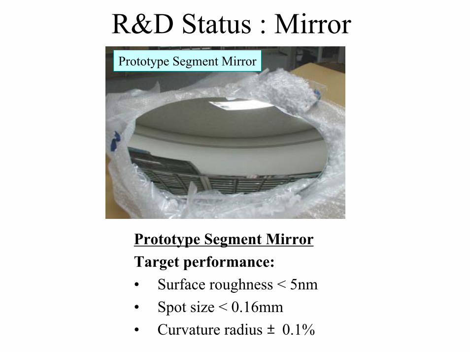
R&D Status : MirrorPrototype Segment Mirror
Prototype Segment MirrorTarget performance:• Surface roughness < 5nm• Spot size < 0.16mm• Curvature radius ±0.1%

Mirror: Surface Roughness Surface Roughness was measured with interferometerRs=R0・exp[–(4πσ/λ)2]
σ:surface roughness (rms) λ:wavelength
⇒ Very important to keep high reflectivityResults: σ~1nm < 5nm ⇒ OK
Ex.) σ=5nm, λ=350nmRs = R0 ・ 0.97 ⇒ 3% loss
σ=1nm, λ=350nm ⇒ 0.1% loss

Mirror: Spot Size
RMS=0.20mm RMS=0.11mm
RMS=0.15mmRMS=0.08mm
mirror
Focus image w/ CCD
diffuse light
~radius of mirror’s curvature
Setup of spot size measurementsSpot images of 4 prototype segment mirrors
3 of 4 mirrors meats the spot size requirement, and the cause of bad spot size has already been fixed.
LED

Mirror: Curvature RadiusCurvature radius was measured with Newton standard.R discrepancies between segment mirrors should smaller than 0.1%R discrepancies ≦ 0.7% ⇒ OK
Newton Standard
Setup of mirrors curvature measurement Newton’s ring

R&D Status : MirrorPrototype Segment Mirror
Prototype Segment MirrorTarget performance:• Surface roughness < 5nm• Spot size < 0.18mm• Curvature radius ±0.1%
Prototype mirrors showed excellent performance.Thus production method for segment mirrors has been fixed.

R&D Status : Acrylic Corrector Lensφ200mm Corrector Lens Sampling
Surface roughness
Slope accuracy
Measured by UA3P (ultra-high accuracy 3Dprofilometer)
Direct measurements of lens surface show:• surface roughness < 10nm• slope accuracy < 1 arcminSmall prototype is OK!
Next Step:much larger lens sampling

Lens: φ630mm Prototype
Prototype lens
Φ630mm lensSurface roughness:
Ra=10nm

R&D Status : Lens I.I.Modification from Commercial X-ray I.I.
200mm
photocathode
phosphorscreen
vacuum tube
electrodes
electron tracks
φ400mm φ25mmFocal sphere CMOS sensor
Patent Pending
The lens I.I. works as the focal sphere detector which reduces the image size into solid state imaging devices.

Astigmatism in Electric LensSource: energy and angular distribution
of photoelectron
cos θ distribution
Peak at ~0.5 eV Input screen
Electron path
Output screen
This is astigmatism
Photoelectron has angular distribution
This width means astigmatism to minimize

Lens I.I. : Resolution of Electrostatic LensPosition and supplied voltage of electrodes have been optimized, and the resolution was estimated.
(mm) (mm)
(mm)(mm)
Using electron-ray trace simulation
requirement= matched w/ spot size
0°
Optimized electric lens meets the resolution requirement
matched with the spot size of the optical system.
25°

Lens I.I. : Designing the Input WindowModification from X-ray II• Material: Al+CsI phosphor UV-transparent glass• Shape: Partial sphere to match focal surface of the telescope
Pressure endurance: one of the most critical issue of the input glass
FEM Stress AnalysisAxisymmetric 2d model
crack origin
wavefront
Burst Test
wavefront
To keep tensile stress below 10MPa crack origin = the weakest point
Design of input window was fixed.

Lens I.I.: How to Make Input Window (1)
Only his part will be used as a “input window”.
A “seed” is blowed into a mold, and then took out from the mold.
“Seed” of input glass

Lens I.I.: How to Make Input Window (2)Kovar ringwelded to I.I. tube.
Final fire polishing
Melting and bonding the input glass window and the Kovar-ring part.
Chucking of a input window
Lathe

Lens I.I.: Current Status of Input Window
Finished Sample (Polished)
Setup of the pressure endurance test: Pressurizing after pumping the inside.
Evaluation of pressure endurance:Maintain 5 minutes under the pressure of 3 atm.⇒ ~50-years endurance
Sufficient Pressure Endurance
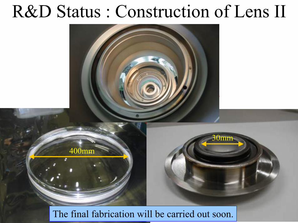
R&D Status : Construction of Lens II
Input Photocathode Window
200mm
Phosphor Kovar flange
SUS flange
FOP
Output Phosphor Screen
400mm30mm
The final fabrication will be carried out soon.

R&D Status : Sub-TelescopeIntegration test of optical system• Achieve 1 arcmin resolution• Develop fabrication processes
Lens mount adjuster
Mirror adjuster
frame
mirror
lens
I.I.

Sub-Telescope: Mirror Arrangement
All mirrors will be mounted within a few days.
1. Cut to mount 4 segment mirrors2. No deterioration after cut
S.Yamada

Sub-Telescope: φ630mm Lens MountLens holding
Lens mounting
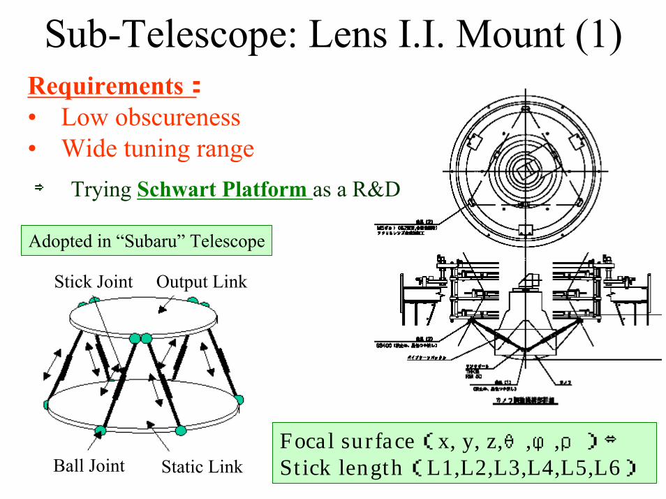
Sub-Telescope: Lens I.I. Mount (1)
Focal surface(x, y, z,θ,φ,ρ)⇔ Stick length(L1,L2,L3,L4,L5,L6)
Stick Joint
Ball Joint Static Link
Output Link
⇒ Trying Schwart Platform as a R&D
Requirements:• Low obscureness• Wide tuning range
Adopted in “Subaru” Telescope

Sub-Telescope: Lens I.I. Mount (2)Utilizes commercial parts:Ball and stick joints
Lens I.I. mounting test:Schwart Platform works well.

SummaryOptical System
We have adopted the modified Baker-Nunn optics which has the capability to achieve 1 arcmin resolution within the whole FOV of 50o x 50o.
R&D Status• Mirror : prototyping OK. Mass production preparation• Corrector lens : small prototype is OK. Φ630 mm lens
has been produced.• Lens II : components design is fixed, and the fabrication
will be carried out soon. • Sub-telescope : integration test and final estimate of
resolution of Ashra optics.


Ashra CollaborationY. Aita1, T. Aoki1, Y. Arai2, Y. Asaoka1, T. Browder3,T. Hayashino5, W. S. Hou6, Y. B. Hsiung6,M. Ieiri2, M. Jobashi1, C. Jui8, J. Learned3, E. Loh8, N. Manago1, S. Matsuno3,J. Matthew8, K. Nakai10, S. Nakamura12, S. Ogawa13, A. Okumura1,S. Olsen3, K. Sakurazawa14, M. Sasaki1, N. Sugiyama15, Y. Tanaka16,N.Ujiie2,V. Vladimir8, M. Z. Wang6, Y. Watanabe14, S. Yamada1, and K. Yoshimura2
(1) Institute for Cosmic Ray Research, Univ.Tokyo, Japan, (2) High Energy Accelerator Research Organization, Japan, (3) University of Hawaii, USA, (5) Tohoku University, Japan, (6) National Tai-wan University, Taiwan, (8) University of Utah, USA, (10) Tokyo University of Science, Japan, (11) Dept. of Physics, Univ.Tokyo, Japan, (12) Yokohama National University, Japan, (13) Toho University, Japan, (14) Tokyo Institute of Technology, Japan, (15) National Astronomical Observatory, Japan, (16) Nagasaki Institute of Applied Science, Japan

Ashra Project PlanAshra-1 PI
M.Sasaki
Expected Event Rate for VHEν• GRB : 2 /yr• AGN : 26 /yr• GZK : 2 /yr

Earth and Mountain Skimming ντUltra Long Baseline
Neutrino Oscillationνe : νµ: ντ = 1:1:1search for δm2>10-17eV2
pseudo-Dirac-ν? (Beacom et al.)
Tau DominantTau range ~10km
Muon range ~1km
1200ντ ⇒ 1τ (>1/10Εν)Maunaloa Mass >1000Km3weq
ν Arrival Direction Conservation High Lorentz boost
Accuracy <1arcmin(Εν >10PeV)
AshraStation
Mt. Maunaloa
Mt. Hualalai
Interaction with Earth or Mountain

Ashra EHEν Sensitivity
curve:differential flux corresponding 1event/yr/energy decadeline:90% CL for E-2 flux

Comparison
Excellent cost-performance and originality

Earth-skimming tau ν
MC performance for EHEν
1.925.95.41.60.31.3
GZK νAGN-jet
AGN-coreGRBTD
Z-burst
Events/yrModel

MC performance: EHECR
Auger×10
p 1017eV
Stereo analysis
Stereo Event Rate (duty10%)
341020eV2591019.5eV13241019eV
Events/yrThreshold

Advantages of Fine Imaging
1分角分解能
空気シャワー蛍光
1度角の分解能
従来の大気蛍光望遠鏡
Virgo Cluster
1分角の分解能
Virgo Cluster
Ashra望遠鏡
Distant shower
1 arcmin resolution
1 degree resolution
1 arcmin resolutionEquivalent to human “eye”
resolution
Observation of GRB optical flash (Ioka’s suggestion)
Accurate estimation of arrival directionIdentification of appearance from earth or mountain
Sensitivity up!
trigger S/N
imaging of distant shower


Very High Energy NeutrinosGamma Ray BurstGamma Ray Burst
加速された陽子
ppγ
π0γγ
np
νμπ+γ
μ+ e+
νe _νμ
Active Galactic NucleiActive Galactic Nuclei
n
Ashra-1 PIM.Sasaki
(VHE ν’s)
Proton Acceleration in AGN
CMBRCR CR
Earth
GZK GZK MechanismMechanism
Studying origin and propagation of VHE cosmic raysStudying origin and propagation of VHE cosmic rays

Ashra-1 PIM.SasakiDetection of VHE ν’s
gamma proton
atmosphere
neutrino
earth
Air-shower emitting lights (fluorescence/Cherenkov)
ν-ID : upward/horizontal air-shower
Imaging w/ I.I.+ CMOS sensor
Ashra Project PurposeAshra-1 PI
M.Sasaki

Direct Detection of VHE νProton Acceleration in AGN
ppγ
π0γγ
np
νμπ+γ
μ+ e+
νe_νμ
To identify proton acceleration, detection of VHE neutrinos plays the key role.

Detection Technique of EHECR p, Fe,γ,νinteraction
25 km
6 kmXmax=800g/cm21018eV proton
Fluorescence Telescope
Fluorescence
~5 UV γ/e/m
Ground sampling
1~2km
Cherenkov Telescope
Cherenkov
Air 1000g/cm2
= 28 rad. len.
= 11 int. len. ⇒
⇒
⇒
⇒
EHECRs
interacting at the upper atmosphere
Air shower
emitting fluorescence and Cherenkov photons
gathering lights w/ telescope

Advantages of Fluorescence Technique1. Measuring AS
longitudinal development2. Stereo Observation
ステレオ再構成
Clear identification of VHEν
Geometrical reconstructiongamma proton
atmosphere
neutrino
earth
⇒ 1st Observation of VHE-ν ⇒High-resolution Telescope

Ashra Optics : Components
NIM A492 (2002) 49Lens II Segmented mirrors
Telescope frame= mount & adjust
structure
Acrylic corrector lenses
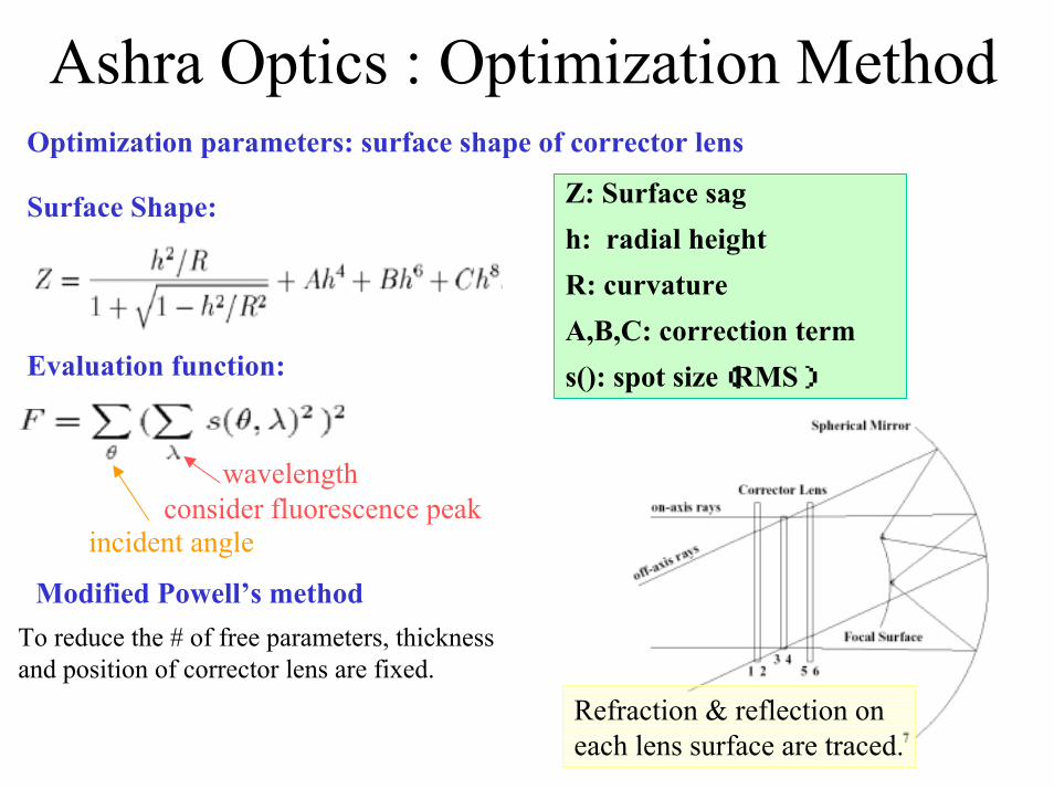
Ashra Optics : Optimization MethodOptimization parameters: surface shape of corrector lens
Z: Surface sagh: radial heightR: curvatureA,B,C: correction terms(): spot size(RMS)
Surface Shape:
Evaluation function:
wavelengthconsider fluorescence peak
incident angle
Refraction & reflection on each lens surface are traced.
Modified Powell’s methodTo reduce the # of free parameters, thickness and position of corrector lens are fixed.

Region obscured by the focal surface25° 0°
Permeability:Region not obscured by the focal surface
> 50%

R&D Status : MirrorStructure Analysis:Estimate surface sag caused by self weight using finite element method ⇒design mounting system and determine thickness of the mirror
Material: Tempax glass (Schott corp.)Shape: segmented spherical mirrorProcess: heating a planar glass on a
ceramic mold plate
Sampling of segmented mirror

Prototype of Segment MirrorThe segment mirror is shaped by heating a planar glass on a ceramic mold plate in the temperature controlled electric oven.
To improve spot size:• A support disk is glued before polishing• Support disk itself is made of glass• Polishing time: 16 hr

Prototype Mirror : Spot Size Measurements
CCD&LED
Mirror
Stage
mirror
L
LED
Spot image in CCD
diffuse light
~ radius of mirror curvature

200mm
photocathode
phosphorscreen
vacuum tube
electrodes
electron tracks
R&D Status : Lens II
Focal sphere ⇒ CMOS sensorφ400mm φ25mm
Modification from Commercial X-ray II
1. Input window: Al+CsI phosphor ⇒UV-transparent glass2. Electric lens: Design new field configuration3. Output window: Plane glass ⇒ Spherical FOP ⇒Patent Pending

Resolution Matching1 arcmin resolution ⇒ σ=0.16 mm @focal surface=I.I. input surface
2.8 Lp/mm ⇒σ= 0.12 mm
(along one axis)
16 inch X-ray I.I. (commercial):4.6Lp/mm @ input surface (magnification factor~10)
Requirement: 3 Lp/mm @ I.I. Input surface
Line pair (Line pair (LpLp) ) ⇔σ⇔σ

UA3PUltra-high Accuracy 3D Profilometer
UA3P uses a nondestructive laser and atomic force probe to measureaspherical surfaces with an accuracy from 0.01 to 0.05 µm. It features the finest stylus, with a tip radius of curvature measuring just 2 micron. The stylus, which is diamond, is key to obtaining the high precision accuracy of 10nm.

Adjustment Precision
0.1[arcmin]0.03 [arcmin]θ
0.05 [mm]0.02 [mm]ZXY 0.05 [mm]0.02 [mm]Mirror
0.8[arcmin]1[arcmin]θ
0.05[mm]0.3 [mm]Z
0.2[arcmin]0.2[arcmin]θ
0.1[mm]0.2 [mm]Z
XY
XY 0.1[mm]
0.1[mm]0.7 [mm] I.I.
0.6[mm]Lens
RequiredMounting Precision
1st Adjustment Precision
Components

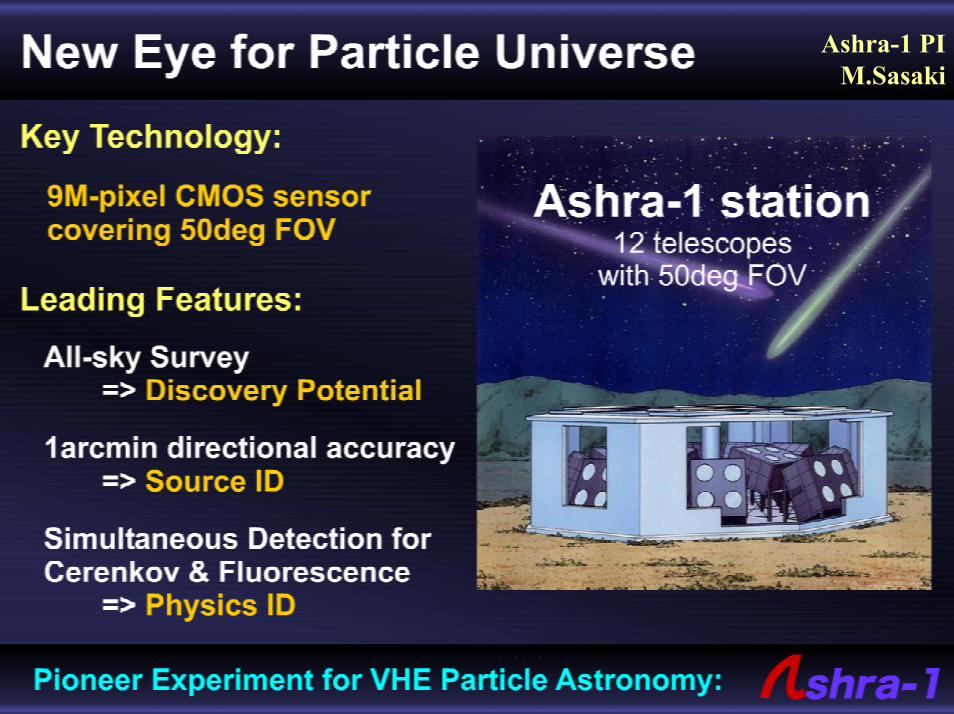
Ashra DetectorAshra is a new air Cherenkov & fluorescence detector.
Distinctive Features:• All-sky Survey ⇒ 2πsr• Higher resolution ⇒ 1 arcmin• Simultaneous observation
• TeVγ, • EHE p/γ, • VHEν⇒ Sugiyama-san’s and
Kohri-san’s talks(OG2.5-14 Aug.5, HE3.4-5 Aug.6)
Ashra station:• 12 telescopes / station
• All-sky (2πsr) / 80M pixels