Embed Size (px)
Citation preview
IEEE TRANSACTIONS ON CIRCUITS AND SYSTEMS—I: FUNDAMENTAL THEORY AND APPLICATIONS, VOL. 50, NO. 4, APRIL 2003 557
Optimal Design of Frequency-Response-MaskingFilters Using Semidefinite Programming
Wu-Sheng Lu, Fellow, IEEE,and Takao Hinamoto, Fellow, IEEE
Abstract—Since Lim’s 1986 paper on the frequency-response-masking (FRM) technique for the design of finite-impulse responsedigital filters with very small transition widths, the analysis anddesign of FRM filters has been a subject of study. In this paper,a new optimization technique for the design of various FRM fil-ters is proposed. Central to the new design method is a sequence oflinear updates for the design variables, with each update carriedout by semidefinite programming. Algorithmic details for the de-sign of basic and multistage FRM filters are presented to show thatthe proposed method offers a unified design framework for a va-riety of FRM filters. Design simulations are included to illustratethe proposed algorithms and to evaluate the design performance incomparison with that of several existing methods.
Index Terms—Frequency-response-masking filters, optimal de-sign, semidefinite programming.
I. INTRODUCTION
SINCE the publication of [1], the frequency-response-masking (FRM) technique for the design of finite-impulse
response (FIR) digital filters with very narrow transition bandshas been a subject of study [2]–[9]. As a result, in many cases,it has become the method of choice primarily because of theconsiderably reduced realization complexity it offers comparedwith other available options [5], [8].
As illustrated in Fig. 1(a), abasicFRM filter involves a linear-phase prototype filter up-sampled by , a pair of linear-phase masking filters , and a delay line that,together with the prototype filter, helps form a linear-phase com-plementary pair [1]. For additional reduction of re-alization complexity, the prototype filter itself may be realizedwith a basic FRM filter, yielding amultistageFRM filter [1],[5], see Fig. 1(b) for a two-stage FRM filter structure. Given anup-sampling factor, lengths of the subfilters involved, and pass-band/stopband edges, the design of a basic or multistage FRMfilter is usually carried out byseparatelydesigning the subfil-ters [1], [5], [6]. As such, the FRM filter obtained is only subop-timal. In [9], a two-step optimization technique for the optimaldesign of basic FRM filters is proposed. In the first step of themethod, an initial FRM filter is designed by alternately opti-mizing the prototype filter and masking filters. The second step
Manuscript received February 20, 2002; revised October 30, 2002. This paperwas recommended by Associate Editor N. Ling.
W.-S. Lu is with the Department of Electrical and Computer Engi-neering, University of Victoria, Victoria, BC V8W 3P6, Canada, (e-mail:[email protected]).
T. Hinamoto is with the Graduate School of Engineering, HiroshimaUniversity, Higashi-Hiroshima 739-8527, Japan (e-mail: [email protected]).
Digital Object Identifier 10.1109/TCSI.2003.809809
then refines the design using an algorithm in [10]. Although theoptimal design of multistage FRM filters was not addressed in[9], the method in [9] appears to be, at least in principle, appli-cable to such a design. However, as the number of filter stagesincreases, a great many of the subfilters need to be optimizedalternately in the first step of the method, making the designprocess increasingly involved. In this paper, we present a ratherdifferent optimization technique in which the set of filter coef-ficients ofall subfilters is treated as a single design vector andan optimal basic FRM filter is designed through a sequence oflinear updates for the design variables, with each update carriedout in a semidefinite programming (SDP) framework. As willbe demonstrated by design examples, starting with a reasonableinitial design, the proposed algorithm converges to an optimizeddesign with performance considerably better than that of [1] andcomparable with that of [9]. An advantage of the proposed de-sign methodology is that with straightforward modifications itcan be readily extended to multistage FRM filters. We shall elab-orate on this point in Sections IV and V with algorithmic detailsfor the class of two-stage FRM filters and simulation results.
The second issue to be addressed in this paper is the op-timal design of FRM filters withreduced passband group delay.Linear-phase FIR filters have constant group delay in the en-tire frequency band, but for a filter with very narrow transitionwidth, the group delay can be exceedingly large, a property notdesirable in many applications. Note that although linear-phaseFRM filters have been successful in reducing realization com-plexity, its group delay is even larger than that of the direct-formFIR filter with the same approximation accuracy. For a linear-phase FRM filter with a large up-sampling factor, its largegroup delay is dominantly contributed by the prototype filter.Therefore, if the prototype filter has a nonlinear phase responsewith a reduced passband group delay, say, and if the delayline [the lower-left block in Fig. 1(a)] is accordingly modifiedto , then the filter is expected to have its passband groupdelay reduced by where is the length ofthe prototype filter. Hence, the reduction in group delay can besignificant especially when is large. In this paper, we pursuethis idea and show that, by a joint optimization of the entire setof subfilters, the prototype as well as masking filters all con-tribute to minimizing the fluctuation in the reduced passbandgroup delay. Furthermore, we extend the design method to themultistage FRM filters with reduced group delay.
The paper is organized as follows. Section II gives a briefoverview of the FRM filtering and some basic elements of SDPthat we need in the rest of the paper. Section III describes thecore of the design methodology based on which our algorithmsare developed in Sections IV and V, respectively. Illustrative
1057-7122/03$17.00 © 2003 IEEE
558 IEEE TRANSACTIONS ON CIRCUITS AND SYSTEMS—I: FUNDAMENTAL THEORY AND APPLICATIONS, VOL. 50, NO. 4, APRIL 2003
(a)
(b)
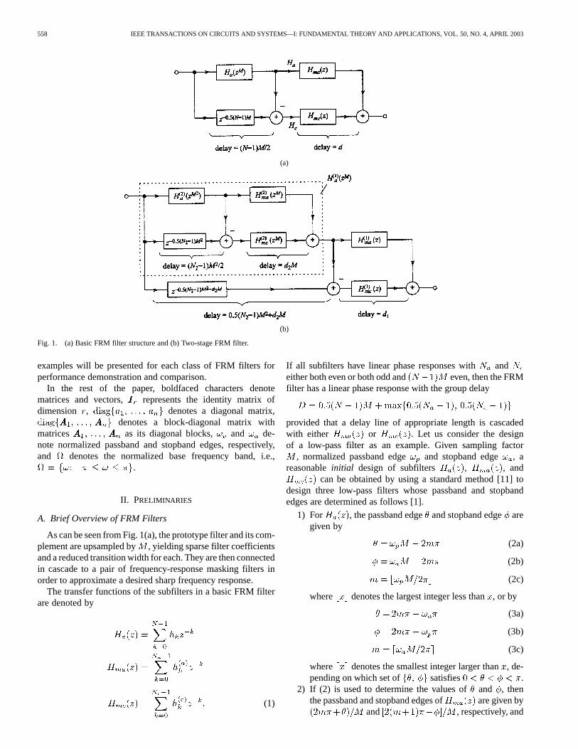
Fig. 1. (a) Basic FRM filter structure and (b) Two-stage FRM filter.
examples will be presented for each class of FRM filters forperformance demonstration and comparison.
In the rest of the paper, boldfaced characters denotematrices and vectors, represents the identity matrix ofdimension , denotes a diagonal matrix,
denotes a block-diagonal matrix withmatrices as its diagonal blocks, and de-note normalized passband and stopband edges, respectively,and denotes the normalized base frequency band, i.e.,
.
II. PRELIMINARIES
A. Brief Overview of FRM Filters
As can be seen from Fig. 1(a), the prototype filter and its com-plement are upsampled by , yielding sparse filter coefficientsand a reduced transition width for each. They are then connectedin cascade to a pair of frequency-response masking filters inorder to approximate a desired sharp frequency response.
The transfer functions of the subfilters in a basic FRM filterare denoted by
(1)
If all subfilters have linear phase responses with andeither both even or both odd and even, then the FRMfilter has a linear phase response with the group delay
provided that a delay line of appropriate length is cascadedwith either or . Let us consider the designof a low-pass filter as an example. Given sampling factor
, normalized passband edge and stopband edge , areasonableinitial design of subfilters , , and
can be obtained by using a standard method [11] todesign three low-pass filters whose passband and stopbandedges are determined as follows [1].
1) For , the passband edgeand stopband edgearegiven by
(2a)
(2b)
(2c)
where denotes the largest integer less than, or by
(3a)
(3b)
(3c)
where denotes the smallest integer larger than, de-pending on which set of satisfies .
2) If (2) is used to determine the values ofand , thenthe passband and stopband edges of are given by
and , respectively, and
LU AND HINAMOTO: OPTIMAL DESIGN OF FRM FILTERS USING SDP 559
the passband and stopband edges of are given byand , respectively.
3) If (3) is used to determine the values ofand , thenthe passband and stopband edges of are given by
and , respectively, andthe passband and stopband edges of are given by
and , respectively.
B. SDP
SDP is a relatively new optimization methodology whichis primarily concerned with minimizing a linear or convexquadratic objective function subject to linear-matrix inequality(LMI) type constraints that depend on the design variablesaffinely [12]. The class of SDP problems most relevant to thedesign problems of interest is expressed as
minimize (4a)
subject to: (4b)
(4c)
where , for areknown symmetric matrices and denotes thatis positive semidefinite at . Note that the constraint matrix
in (4) isaffinewith respect to . SDP includes both linearand quadratic programming as its special cases and representsa subclass of convex programming that covers many optimiza-tion problems encountered in various engineering disciplines.Many interior-point methods which have proven efficient forlinear programming have recently been extended to SDP [12],[13] and efficient software implementation of various SDP algo-rithms are available. In particular we mention the LMI ControlToolbox [14], SeDuMi [15], and SDPT3 Toolbox [16], all ofwhich work with MATLAB.
III. OPTIMIZATION METHODOLOGY
In this section, we describe the core of the optimization tech-nique based on which the design algorithms for various FRMfilters will be developed in the subsequent sections. As such,our description will be given in a setting more general than eachindividual algorithm in Sections IV and V.
Let be a desired real-valued or complex-valued func-tion of frequency variable , and be a real-valued orcomplex-valued function of , which depends on a real-valuedparameter vector . We seek to find a vector thatsolves the weighted minimax optimization problem
minimize maximize (5)
where is a weighting function. With different inter-pretations for and , the problem in (5) coversmany minimax design problems for digital filters, includingthose to be addressed in Sections IV and V.
Let be an upper bound of on. As the first step of the optimization we convert the problem
in (5) into a constrained minimization problem
minimize (6a)
subject to: for
(6b)
Suppose we have a reasonable initial pointto start the design,and we are now in theth iteration. For a nonlinear and smooth
in a vicinity of , we can write
where is the gradient of with respect to andevaluated at . Hence, provided that is small, with
we have
(7)
where and are the real and imaginary parts of, respectively, and
with , , , and being thereal and imaginary parts of and , respectively.From (6) and (7), it follows that an approximate solution of (6)in the th iteration can be obtained by solving the followingproblem:
minimize (8a)
subject to: for
(8b)
(8c)
where is a prescribed bound to control the magnitude of, andfor notation simplicity, the dependence of , andon has been omitted.
By using linear algebraic arguments, it can be readily shownthat the constraint in (8b) holds if and only if
for (9)
and that the constraint in (8c) holds if and only if
(10)
If we treat the upper bound as an additional design variableand define an augmented vector as , then theobjective function in (8a) can be expressed as with
560 IEEE TRANSACTIONS ON CIRCUITS AND SYSTEMS—I: FUNDAMENTAL THEORY AND APPLICATIONS, VOL. 50, NO. 4, APRIL 2003
, and the problem in (8) can be formulatedas
minimize (11a)
subject to: (11b)
where
and is a set of dense grid pointsin the frequency bands of interest. Note that matrix in(11b) is affine with respect to vectorand the problem in (11)is, therefore, an SDP problem.
Having solved the problem in (11) for a minimizer
vector is used to update as
The iteration continues until becomes insignificant com-pared to a prescribed tolerance.
The original problem in (5) and, equivalently, the problemin (6) are highly nonlinear and nonconvex optimization prob-lems. As such, the above method, if it converges, only providesa local minimizer for the problem. Among other things, the per-formance of such a local solution depends largely on how theinitial point is chosen. Fortunately, for FRM filter designs, atechnique that generates a reasonably good initial point is avail-able, see [1] and Section II-A. Concerning the convergence ofthe method, although a rigorous proof is presently not available,in our simulations when the method was applied to design avariety of FRM filters, we had not detected a single failure ofconvergence. One might attribute the success of the proposedmethod to three factors: 1) the global convergence of each sub-problem in (11) when an interior-point convex programming al-gorithm is applied; 2) the use of constraint (8c) that validates thekey approximation in (7); and 3) the use of a good initial point.
Another related issue is the convergence rate or, in a moregeneral term, the computational efficiency. From the abovedescription of the method, it is quite clear that the computa-tional efficiency is determined by how efficient each individualSDP problem in (11) is solved and how many linear updatesare needed to reach a minimizer of (6). For the former, mostof the algorithms that are presently available for solving theSDP problem (11) are so-called polynomial-time algorithms,meaning that the amount of computations required is boundedby a polynomial of the data size [13]. Consequently, thecomputational complexity for problem (11) is affordable fortoday’s computing devices even for designing high-order FRMfilters, and it will increase only moderately when the size ofthe problem increases. For the latter, with a given boundin constraint (8c), the number of updates needed depends onhow far the initial point is from the minimizer. In the context
of FRM filter design, with an initial point generated by themethod in [1], the number of updates required is typically inthe range of 10 to 30.
It should also be pointed out that although (11) is merelyan approximationof (6), as the iteration continues and thelocal minimizer gets closer, the increment vectorobtainedby solving (11) gradually shrinks in magnitude and within alimited number of iterations it eventually becomes such a valuethat the updated solution point is practically the same as thetrue minimizer.
In summary, we have described a method for minimaxoptimization of an objective function that is frequently en-countered in filter design problems and is allowed to behighly nonlinear. The method proposed here accomplishes theoptimization through a sequence of linear updates where eachupdate is solvable in an SDP setting. The usefulness of thismethodology will be demonstrated in the next two sectionswhere various FRM filter design problems are addressed.
We conclude this section with a remark on the scale of theSDP problem in (11). In the general case, as addressed abovewhere both and are complex-valued functions,the dimension of the LMI constraint in (11b) is where
is the number of design variables andis the total number ofgrid points in . If, however, both and are real-valued functions (which is indeed the case encountered in thedesign oflinear-phaseFRM filters), then the gradientis also real-valued and the matrix in (9) becomes a
matrix and the constraint in (9) becomes
for
(12)where . The size of matrix
in (11b) in this case is reduced to . In atypical FRM filter design problem, the “do-not-care” region isvery small, hence the grid points in set need to be distributedover almost the entire base bandand is likely in the rangeof 5 10 to 10 . Thus, for an FRM filter of moderate order, thenumber of constraints can be in the range of 1.510 to 310 (in a variety of FRM filter designs that we have conducted,it was found that as long as is in the above range, changingfrom one value to another does not lead to significant changes inthe performance of the FRM filter). Fortunately, a robust SDPsolver (such as those available in the MATLAB LMI ControlToolbox [14]) today can easily handle a SDP problem with thesize of in the range of several thousand on a Pentium PCwithout numerical difficulties.
IV. OPTIMIZATION OF FRM FILTERS: BASIC AND
MULTISTAGE STRUCTURES
Throughout the section, all subfilters are assumed to havelinear-phase responses, and the lengths of the masking filtersat any given stage are either both even or both odd.
A. Basic FRM Filters
1) Frequency Response and Its Gradient:The reader is re-ferred to the structure in Fig. 1 and (1). Without loss of gener-
LU AND HINAMOTO: OPTIMAL DESIGN OF FRM FILTERS USING SDP 561
ality, the FRM filter can be treated as a zero-phase FIR filter,and the frequency response of the FRM filter is then given by
(13)where
if odd
if even
if odd
if even
if odd
if even
if odd
if even
if odd
if even
if odd
if even
and the design variables are put together as parameter vector
The group delay of the FRM filter is given by
(14)
where , and the gradient ofwith respect to is given by
(15)
where .2) Desired Frequency Response and Weighting Func-
tion: For the sake of presentation clarity, we consider the caseof designing a low-pass FRM filter with up-sampling factor
, normalized passband edge and stopband edge . Thedesired in this case becomes
for
for(16)
and a staircase weighting function
for
for
elsewhere
(17)
is chosen, where is a positive scalar to weigh the stopbandrelative to the passband.
3) Initial Design: Given parameters , , , , ,and , a reasonable initial design can be obtained by de-signing low-pass , , and as discussed inSection II-A. It is important to stress that although (as will bedemonstrated by simulations shortly) the optimized doesnot at all look like a low-pass filter, the initial design preparedhere worked flawlessly in a variety of FRM designs we haveattempted.
4) Placement of Grid Points and Bound: Our designpractice has indicated that relatively denser grid points should beplaced in the regions near the band edges in both passband andstopband so as to avoid using unnecessarily large number of totalgrid points. We recommend that about 25% of the grid points beplaced in the 10% of that band nearest to the band edge.
As expected, the value of boundin constraint (8c) is takento be proportional to the dimension of vector, namely,
where denotes the dimension of and is a constantfactor. It was found in our simulations that the norm constraint(8c) worked effectively when the value ofwas in the range of[0.005, 0.05].
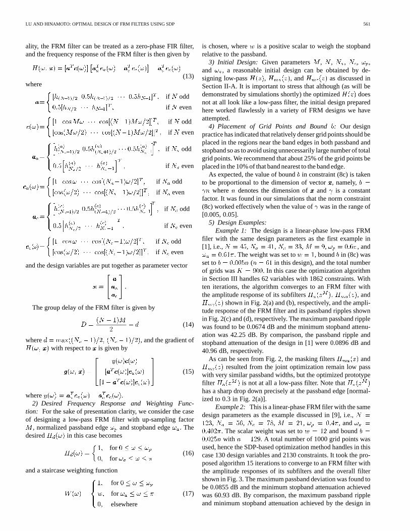
5) Design Examples:Example 1: The design is a linear-phase low-pass FRM
filer with the same design parameters as the first example in[1], i.e., , , , , , and
. The weight was set to , bound in (8c) wasset to ( in this design), and the total numberof grids was . In this case the optimization algorithmin Section III handles 62 variables with 1862 constraints. Withten iterations, the algorithm converges to an FRM filter withthe amplitude response of its subfilters , and
shown in Fig. 2(a) and (b), respectively, and the ampli-tude response of the FRM filter and its passband ripples shownin Fig. 2(c) and (d), respectively. The maximum passband ripplewas found to be 0.0674 dB and the minimum stopband attenu-ation was 42.25 dB. By comparison, the passband ripple andstopband attenuation of the design in [1] were 0.0896 dB and40.96 dB, respectively.
As can be seen from Fig. 2, the masking filters andresulted from the joint optimization remain low pass
with very similar passband widths, but the optimized prototypefilter is not at all a low-pass filter. Note thathas a sharp drop down precisely at the passband edge [normal-ized to 0.3 in Fig. 2(a)].
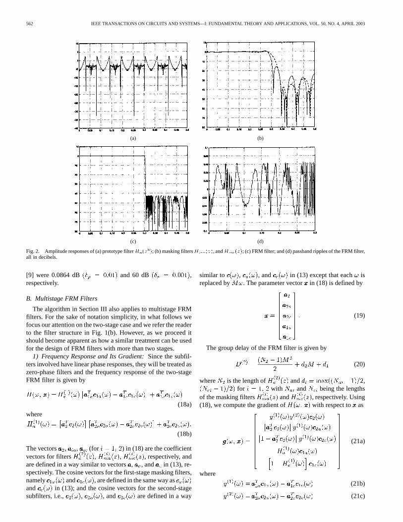
Example 2: This is a linear-phase FRM filer with the samedesign parameters as the example discussed in [9], i.e.,
, , , , , and. The scalar weight was set to and boundwith . A total number of 1000 grid points was
used, hence the SDP-based optimization method handles in thiscase 130 design variables and 2130 constraints. It took the pro-posed algorithm 15 iterations to converge to an FRM filter withthe amplitude responses of its subfilters and the overall filtershown in Fig. 3. The maximum passband deviation was found tobe 0.0855 dB and the minimum stopband attenuation achievedwas 60.93 dB. By comparison, the maximum passband rippleand minimum stopband attenuation achieved by the design in
562 IEEE TRANSACTIONS ON CIRCUITS AND SYSTEMS—I: FUNDAMENTAL THEORY AND APPLICATIONS, VOL. 50, NO. 4, APRIL 2003
(a) (b)
(c) (d)
Fig. 2. Amplitude responses of (a) prototype filterH (z ); (b) masking filtersH (z), andH (z); (c) FRM filter; and (d) passband ripples of the FRM filter,all in decibels.
[9] were 0.0864 dB and 60 dB ,respectively.
B. Multistage FRM Filters
The algorithm in Section III also applies to multistage FRMfilters. For the sake of notation simplicity, in what follows wefocus our attention on the two-stage case and we refer the readerto the filter structure in Fig. 1(b). However, as we proceed itshould become apparent as how a similar treatment can be usedfor the design of FRM filters with more than two stages.
1) Frequency Response and Its Gradient:Since the subfil-ters involved have linear phase responses, they will be treated aszero-phase filters and the frequency response of the two-stageFRM filter is given by
(18a)
where
(18b)
The vectors , , (for ) in (18) are the coefficientvectors for filters , , , respectively, andare defined in a way similar to vectors, , and in (13), re-spectively. The cosine vectors for the first-stage masking filters,namely and , are defined in the same way asand in (13); and the cosine vectors for the second-stagesubfilters, i.e., , , and are defined in a way
similar to , , and in (13) except that each isreplaced by . The parameter vector in (18) is defined by
(19)
The group delay of the FRM filter is given by
(20)
where is the length of and ,for with and being the lengths
of the masking filters and , respectively. Using(18), we compute the gradient of with respect to as
(21a)
where
(21b)
(21c)
LU AND HINAMOTO: OPTIMAL DESIGN OF FRM FILTERS USING SDP 563
(a) (b)
(c) (d)
Fig. 3. Amplitude responses of (a) prototype filterH (z ); (b) masking filtersH (z), andH (z); (c) FRM filter; and (d) passband ripples of the FRMfilter, all in decibels.
and is defined in (18b).2) Initial Design: Again, we consider a low-pass filter de-
sign. Given parameters , and, an initial design for a two-stage FRM filter can be readily
obtained in a two-stage manner as follows.
i) Use parameters , and , whereis an arbitrary positive integer for the reason that
will become apparent shortly, to obtain an initial designof , , and by the method inSection II-A. In doing so, we also obtain the values ofand as the passband and stopband edges for .
ii) Now, denote and and use parameters, and to obtain an initial design
of , , and by the same method(in Section II-A). The coefficients of , ,
, , and are now used to form theinitial parameter vector as in (19). As we can see, filter
was not involved in , but just used as an en-tity to which the values of and become meaningfulparameters, and this is why parametercan be chosenarbitrarily.
As can be expected in an-stage FRM filter design, an initialdesign can be generated by repeatedly applying the method inSection II-A times and extract the coefficients of the subfiltersobtained to form vector .
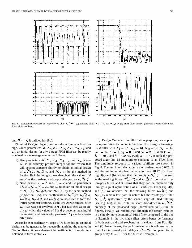
3) Design Example:For illustration purposes, we appliedthe optimization technique in Section III to design a two-stageFRM filter with , , , ,
, , , and . With ,, and (with ), it took the pro-
posed algorithm 18 iterations to converge to an FRM filter.The amplitude response of various subfilters are shown inFig. 4. The maximum deviation in the passband was 0.032 dBand the minimum stopband attenuation was 48.77 dB. FromFig. 4(a) and (b), we see that the prototype as wellas the masking filters and do not act likelow-pass filters and it seems that they can be obtained onlythrough a joint optimization of all subfilters. From Fig. 4(c)and (d), we observe that the masking filters and
remain low pass in nature but the “prototype” filtersynthesized by the second stage of FRM filtering
[see Fig. 1(b)] is not. Note the sharp drop-down inprecisely at the passband edge (normalized to 0.3 in thefigure). Finally, we remark that although the design resultedin a slightly more economical FRM filter compared to the onein Example 1, the two-stage filter offers better performancein both passband and stopband as is evident from Fig. 4(e)and (f). Nevertheless, the performance gain is achieved at thecost of an increased group delay compared to thegroup delay for the filter in Example 1.
564 IEEE TRANSACTIONS ON CIRCUITS AND SYSTEMS—I: FUNDAMENTAL THEORY AND APPLICATIONS, VOL. 50, NO. 4, APRIL 2003
(a) (b)
(c) (d)
(e) (f)
Fig. 4. Amplitude responses of (a) prototype filterH (z ); (b) masking filtersH (z ), andH (z ); (c) “prototype”H (z ); (d) masking filtersH (z) andH (z); (e) FRM filter; and (f) passband ripples of the FRM filter, all in decibels.
V. OPTIMIZATION OF FRM FILTERS WITH
REDUCED GROUPDELAY
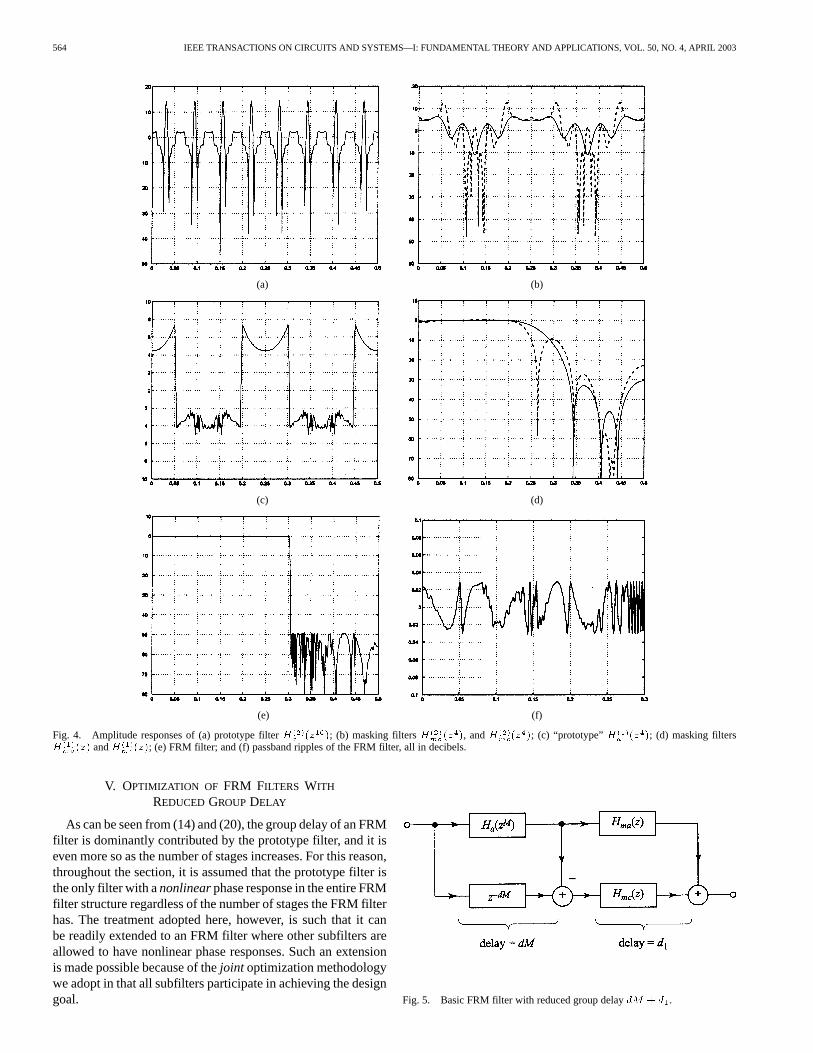
As can be seen from (14) and (20), the group delay of an FRMfilter is dominantly contributed by the prototype filter, and it iseven more so as the number of stages increases. For this reason,throughout the section, it is assumed that the prototype filter isthe only filter with anonlinearphase response in the entire FRMfilter structure regardless of the number of stages the FRM filterhas. The treatment adopted here, however, is such that it canbe readily extended to an FRM filter where other subfilters areallowed to have nonlinear phase responses. Such an extensionis made possible because of thejoint optimization methodologywe adopt in that all subfilters participate in achieving the designgoal. Fig. 5. Basic FRM filter with reduced group delaydM + d .
LU AND HINAMOTO: OPTIMAL DESIGN OF FRM FILTERS USING SDP 565
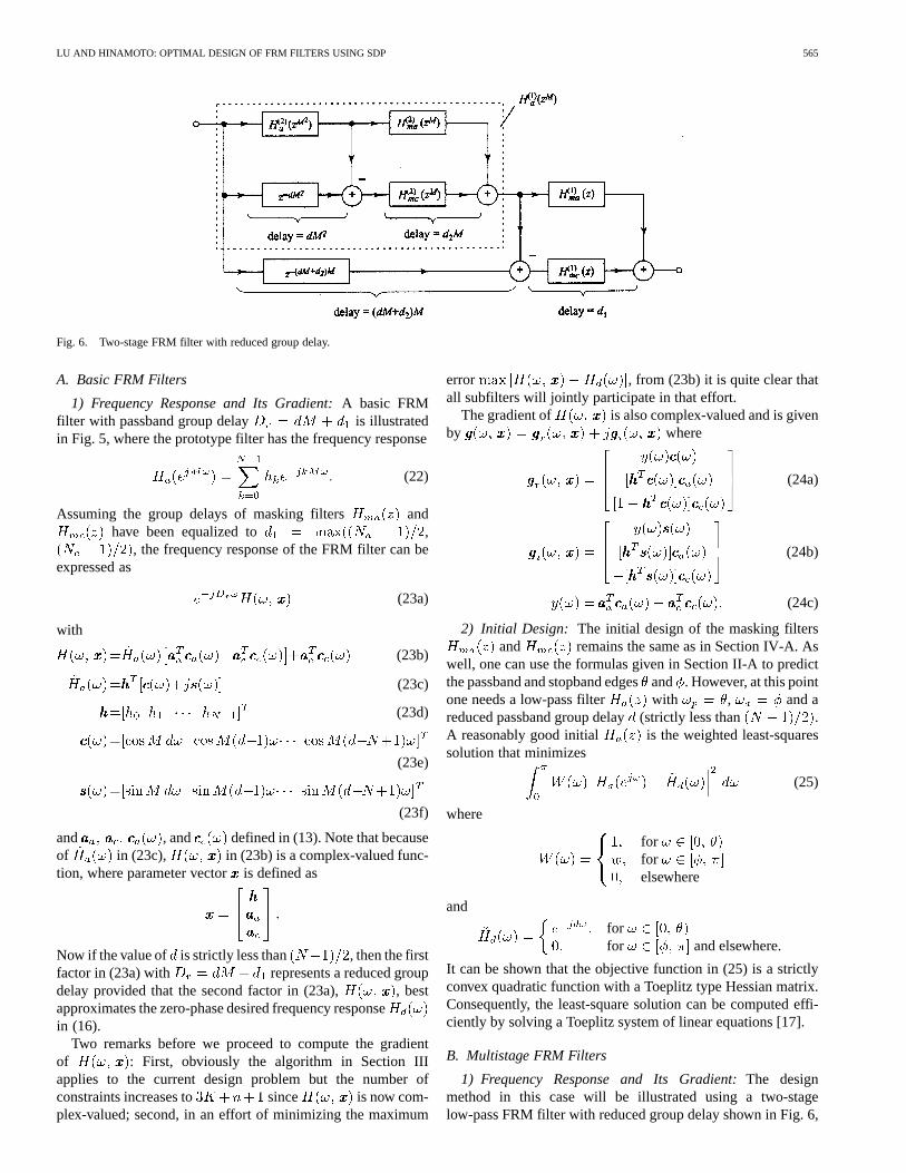
Fig. 6. Two-stage FRM filter with reduced group delay.
A. Basic FRM Filters
1) Frequency Response and Its Gradient:A basic FRMfilter with passband group delay is illustratedin Fig. 5, where the prototype filter has the frequency response
(22)
Assuming the group delays of masking filters andhave been equalized to ,
, the frequency response of the FRM filter can beexpressed as
(23a)
with
(23b)
(23c)
(23d)
(23e)
(23f)
and , and defined in (13). Note that becauseof in (23c), in (23b) is a complex-valued func-tion, where parameter vectoris defined as
Now if the value of is strictly less than , then the firstfactor in (23a) with represents a reduced groupdelay provided that the second factor in (23a), , bestapproximates the zero-phase desired frequency responsein (16).
Two remarks before we proceed to compute the gradientof : First, obviously the algorithm in Section IIIapplies to the current design problem but the number ofconstraints increases to since is now com-plex-valued; second, in an effort of minimizing the maximum
error , from (23b) it is quite clear thatall subfilters will jointly participate in that effort.
The gradient of is also complex-valued and is givenby where
(24a)
(24b)
(24c)
2) Initial Design: The initial design of the masking filtersand remains the same as in Section IV-A. As
well, one can use the formulas given in Section II-A to predictthe passband and stopband edgesand . However, at this pointone needs a low-pass filter with , and areduced passband group delay(strictly less than .A reasonably good initial is the weighted least-squaressolution that minimizes
(25)
where
forforelsewhere
and
forfor and elsewhere.
It can be shown that the objective function in (25) is a strictlyconvex quadratic function with a Toeplitz type Hessian matrix.Consequently, the least-square solution can be computed effi-ciently by solving a Toeplitz system of linear equations [17].
B. Multistage FRM Filters
1) Frequency Response and Its Gradient:The designmethod in this case will be illustrated using a two-stagelow-pass FRM filter with reduced group delay shown in Fig. 6,
566 IEEE TRANSACTIONS ON CIRCUITS AND SYSTEMS—I: FUNDAMENTAL THEORY AND APPLICATIONS, VOL. 50, NO. 4, APRIL 2003
where only prototype filter has a nonlinear phaseresponse and its frequency response is given by
(26)
The frequency response of the two-stage FRM filter can be ex-pressed as
(27a)
where
(27b)
(27c)
(27d)
(27e)
(27f)
(27g)
(27h)
vectors , , , and for are the same asin (18), and vector is defined by
With a value of strictly less than , (27a) rep-resents a frequency response with reduced group delayprovided that in (27c) approximates the zero-phasedesired frequency response in (16). To proceed, we com-pute the gradient of aswhere
(28a)
(28b)
(28c)
and , are defined by (21b) and (21c).2) Initial Design: Initial designs of the two pairs of masking
filters , and , can be ob-tained in the same way as described in Section IV-B-2. Duringthat process, the passband and stopband edges of prototype filter
can also be identified. One can then perform a least-square design of with passband group delayby min-imizing the convex quadratic objective function in (25), see thediscussion in Section V-A-2.
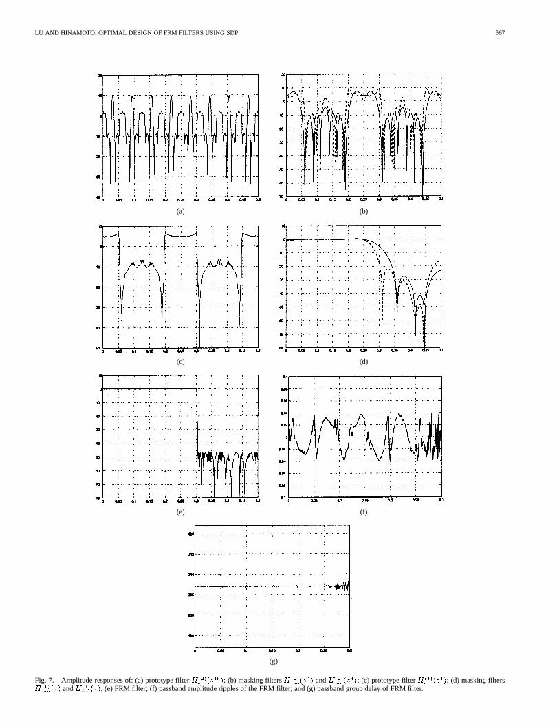
3) Design Example:To illustrate the design method, weapply the optimization method in Section III to design a two-stage FRM filter with , , ,
, , , , , and. The use of represents a group delay reduction of
, a 24% reduction in group delayfrom its linear-phase counterpart. With (with
), and , it took the proposed algorithm 24 it-erations to converge to a two-stage FRM filter. The amplituderesponses of the subfilters as well as the overall FRM filter, andits passband ripples in magnitude and group delay are depictedin Fig. 7. The maximum passband amplitude ripple was 0.04 dBand the minimum stopband attenuation was 46.01 dB. The rel-ative deviation in passband delay was 0.0132. Compared withits linear-phase counterpart which was the design discussed inSection IV-B, slight performance degradation in terms of pass-band ripple and stopband attenuation were observed, a cost forhaving a considerable reduction in group delay.
VI. CONCLUDING REMARKS
In this paper, we have attempted to lay out a methodology foroptimal design of various FRM filters. To conclude, we high-light several features of the design method as follows: a) it isan optimization method that treats the coefficients of all subfil-ters as a single set of design variables regardless of the numberof stages the FRM filter has. As a result, the joint optimizationof all participating subfilters leads to improved design perfor-mance; b) it is a method based on SDP which is a special classof convex programming equipped with efficient interior-pointsolvers for large scale problems, and as such the proposed de-sign algorithms are able to handle designs of high order, mul-tistage FRM filters with linear or nonlinear phase responses;c) it is a method in which various types of FRM filters canbe designed in a unified manner. Consequently, the coding ofthe design algorithms is substantially simplified, with a set ofcore codes in common plus small size routines to fit the set ofcore codes into a specific class of FRM filters; and d) it is amethod that works well as long as it starts with a reasonable ini-tial point. Finally, we stress that the class of FRM filters withreduced group delay offers the designer an additional option forthe tradeoff between realization complexity, performance, andsystem delay.
LU AND HINAMOTO: OPTIMAL DESIGN OF FRM FILTERS USING SDP 567
(a) (b)
(c) (d)
(e) (f)
(g)
Fig. 7. Amplitude responses of: (a) prototype filterH (z ); (b) masking filtersH (z ) andH (z ); (c) prototype filterH (z ); (d) masking filtersH (z) andH (z); (e) FRM filter; (f) passband amplitude ripples of the FRM filter; and (g) passband group delay of FRM filter.
568 IEEE TRANSACTIONS ON CIRCUITS AND SYSTEMS—I: FUNDAMENTAL THEORY AND APPLICATIONS, VOL. 50, NO. 4, APRIL 2003
REFERENCES
[1] Y. C. Lim, “Frequency-response masking approach for the synthesis ofsharp linear phase digital filters,”IEEE Trans. Circuits Syst., vol. 33, pp.357–364, Apr. 1986.
[2] R. Yang, B. Liu, and Y. C. Lim, “A new structure of sharp transition FIRfilters using frequency-response masking,”IEEE Trans. Circuits Syst.,vol. 35, pp. 955–966, Aug. 1988.
[3] G. Rajan, Y. Neuvo, and S. K. Mitra, “On the design of sharp cutoffwide-band FIR filters with reduced arithmetic complexity,”IEEE Trans.Circuits Syst., vol. 35, pp. 1447–1454, Nov. 1988.
[4] T. Saramaki and A. T. Fam, “Subfilter approach for designing efficientFIR filters,” in Proc. 1988 ISCAS, pp. 2903–2915.
[5] Y. C. Lim and Y. Lian, “The optimum design of one- and two-dimen-sional FIR filters using the frequency response masking technique,”IEEE Trans. Circuits Syst. II, vol. 40, pp. 88–95, Feb. 1993.
[6] Y. C. Lim and Y. Lian, “Frequency-response masking approach for dig-ital filter design: Complexity reduction via masking filter factorization,”IEEE Trans. Circuits Syst. II, vol. 41, pp. 518–525, Aug. 1994.
[7] T. Saramaki, Y. C. Lim, and R. Yang, “The synthesis of half-band filterusing frequency-response marking technique,”IEEE Trans. CircuitsSyst. II, vol. 42, pp. 58–60, Jan. 1995.
[8] M. G. Bellanger, “Improved design of long FIR filters using the fre-quency masking technique,” inProc. 1996 ICASSP, pp. 1272–1275.
[9] T. Saramaki and H. Johansson, “Optimization of FIR filters using fre-quency-response masking approach,” inProc. 2001 ISCAS, vol. II, pp.177–180.
[10] S. R. K. Dutta and M. Vidyasagar, “New algorithms for constrained min-imax optimization,”Math. Progr., vol. 13, pp. 140–155, 1977.
[11] A. Antoniou, Digital Filters: Analysis, Design, and Applications, 2nded. New York: McGraw-Hill, 1993.
[12] L. Vanderberghe and S. Boyd, “Semidefinite programming,”SIAM Rev.,vol. 38, pp. 49–95, 1996.
[13] H. Wolkowicz, R. Saigal, and L. Vanderberghe, Eds.,Handbook onSemidefinite Programming. Norwell, MA: Kluwer Academic, 2000.
[14] P. Gahinet, A. Nemirovski, A. J. Laub, and M. Chilali,Manual of LMIControl Toolbox. Natick, MA: The MathWorks, Inc., 1995.
[15] J. F. Sturm, “Using SeDuMi 1.02, a MATLAB toolbox for optimizationover symmetric cones,”Optimization Methods and Software, vol. 11–12,pp. 625–653, 1999. [Online]. Available: http://fewcal.kub.nl/sturm/soft-ware/sedumi.html.
[16] R. H. Tütüncü, K. C. Toh, and M. J. Todd. (2001, Aug.) SDPT3—AMATLAB software package for semidefinite–quadratic-linearprogramming, version 3.0. [Online]. Available: http://www.math.nus.edu.sg/~mattohkc/.
[17] G. H. Golub and C. F. Van Loan,Matrix Computations, 2nded. Baltimore, MD: The Johns Hopkins Univ. Press, 1989.
Wu-Shen Lu (F’99) received the undergraduatedegree in mathematics from Fudan University,Shanghai, China, in 1964, and the M.S. degree inelectrical engineering, and Ph.D. degree in controlscience from University of Minnesota, Minnesota,in 1983 and 1984, respectively.
He was a Post-Doctoral Fellow at the University ofVictoria, Victoria, BC, Canada in 1985 and a VisitingAssistant Professor at the University of Minnesota,in 1986. Since 1987, he has been with the Univer-sity of Victoria, where he is currently a Professor. His
teaching and research interests are in the areas of digital signal processing andapplication of optimization methods. He is the coauthor ofTwo-DimensionalDigital Filters (New York: Marcel Dekker, 1992). He was an Associate Editorof theCanadian Journal of Electrical and Computer Engineeringin 1989, andits Editor from 1990 to 1992. He is presently an Associate Editor for theInter-national Journal of Multidimensional Systems and Signal Processing.
Dr. Lu served as an Associate Editor for IEEE TRANSACTIONS ONCIRCUITS
AND SYSTEMSII from 1993 to 1995, and for IEEE TRANSACTIONS ONCIRCUITS
AND SYSTEMSI from 1999 to 2001. He is a Fellow of the Engineering Instituteof Canada.
Takao Hinamoto (M’77–SM’84–F’01) received theB.E. degree from Okayama University, Okayama,Japan, in 1969, the M.E. degree from Kobe Univer-sity, Kobe, Japan, in 1971, and the Dr. Eng. degreefrom Osaka University, Osaka, Japan, in 1977, allin electrical engineering.
From 1972 to 1988, he was with the Faculty ofEngineering, Kobe University. From 1979 to 1981,he was on leave from Kobe University as visitingmember of staff in the Department of ElectricalEngineering, Queen’s University, Kingston, ON,
Canada. During 1988–1991, he was Professor of electronic circuits in theFaculty of Engineering, Tottori University, Tottori, Japan. Since January 1992,he has been Professor of electronic control in the Department of ElectricalEngineering, Hiroshima University, Hiroshima, Japan. His research interestsinclude digital signal Processing, system theory, and control engineering. Hehas published more than 270 papers in these areas and is the co-editor andco-author ofTwo-Dimensional Signal and Image Processing(Tokyo, Japan:SICE, 1996).
Dr. Hinamoto served as an Associate Editor of the IEEE TRANSACTIONS ON
CIRCUITS AND SYSTEMSII from 1993 to 1995, and presently serves as an Asso-ciate Editor of the IEEE TRANSACTIONS ONCIRCUITS AND SYSTEMSI. He alsoserved as Chair of the 12th Digital Signal Processing (DSP) Symposium heldin Hiroshima in November 1997, sponsored by the DSP Technical Committeeof IEICE. He was the Guest Editor of the special section of DSP in the August1998 issue of theIEICE Transactions on Fundamentals. Since 1995, he has beena member of the steering committee of the IEEE Midwest Symposium on Cir-cuits and Systems, and since 1998, a member of the Digital Signal ProcessingTechnical Committee in the IEEE Circuits and Systems Society. He served asa member of the Technical Program Committee for ISCAS’99. From 1993 to2000, he served as a senator or member of the Board of Directors in the Societyof Instrument and Control Engineers (SICE), and from 1999 to 2001, he wasChair of the Chugoku Chapter of SICE. He played a leading role in establishingthe Hiroshima Section of IEEE, and served as the Interim Chair of the section.He is a recipient of the IEEE Third Millennium Medal.