Embed Size (px)
Citation preview
Xin Zhang, Gang-Len Chang 1
Optimal Guidance of Pedestrian-Vehicle Mixed Flows in Urban Evacuation
Network
Xin Zhang (Corresponding Author) Department of Civil and Environmental Engineering
University of Maryland, College Park, MD 20742 Phone: (301)-405-2638 Fax: (301) 405-2585
Email: [email protected]
Gang-Len Chang Department of Civil and Environmental Engineering
University of Maryland, College Park, MD 20742 Phone: (301)-405-2638 Fax: (301) 405-2585
Email: [email protected]
Submission Date: 7/31/2010 Word Count: 5698 + 25 (15 figures + 10 tables) × 250 = 11948
Paper submitted for the 90th annual meeting of the Transportation Research Board January 2011, Washington D.C.
Xin Zhang, Gang-Len Chang 2
ABSTRACT In metropolitan areas, a potentially large number of pedestrians depend either on transit or other
modes for evacuation, or need to walk a distance to access their passenger cars. In the process of approaching some designated pick-up points for evacuation, the massive number of pedestrians may incur tremendous burden to the vehicles on the roadway network. Thus, an effective coordination between the vehicle and pedestrian flow during the multi-modal evacuation process shall be devised. This paper presents an integrated linear model for design of routing plans for massive mixed pedestrian-vehicle flows within the evacuation zone. The proposed model integrating the pedestrian and vehicle networks can effectively take into their potential conflicts during the evacuation, and generate the optimal routing strategies for guiding evacuees moving toward either the pick-up locations or their parking areas. An illustrating example concerning the evacuation around the M&T stadium area has been presented and seems to indicate promising properties to address the complex interactions between vehicle and pedestrian flows within the evacuation zone. Results of simulation experiments clearly indicate that the failure to account for the conflict movement will yield unrealistic plans that can’t be implemented during the actual evacuation process.
Xin Zhang, Gang-Len Chang 3
1. INTRODUCTION During the emergency evacuation planning and operations, responsible agencies often need to
make the following decisions: (1) choosing the possible shelters and safe destinations; (2) determining the departure rates of each evacuation zone; (3) proposing the routing strategy for evacuees; (4) optimizing the signal timings on major intersections and ramps. Most pioneering studies or programs such as NETVAC [1], DYNEV [2], MASSVAC [3, 4], OREMS [5, 6], and EITS [7] were based on the “trial-and-error” method, resorting to both macro- and micro- simulation tools for performance evaluation. To optimize the vehicle flow distribution during the evacuation, some researchers [8-10] proposed the use of static network flow models. In recent years, it becomes increasingly popular to use dynamic models by applying either dynamic traffic assignment techniques [11, 19-21] or the cell transmission model [12-18]. The heuristic framework [22] and methods have also been proposed, especially in solving multi-objective models [23, 24] for evacuation planning.
Some existing studies on optimization of pedestrian evacuation problems deal mostly with building evacuations [25-27]. For example, Francis etal [28-31] proposed an application, EVACNET, to generate the optimal evacuation plans and estimate the evacuation times for the in-building evacuees. Some researchers explored multi-objective formulations [32-37] to model the building evacuation. Recently, Lin et al. offered a staged evacuation mode [38] for pedestrian flows in the capacity drop environment [39]. Aside from the deterministic models, stochastic properties of the network and the evacuation process have also been studied [40-43].
Note that most existing studies on evacuation focus either on optimizing the vehicle or pedestrian flows during the emergency. However, in metropolitan areas, a potentially large number of pedestrians depend either on transit or other modes for evacuation, or need to walk a distance to access their passenger cars. In the process of approaching some designated pick-up points for evacuation, the massive number of pedestrians may incur tremendous burden to the vehicles on the roadway network. Thus, preventing the formation of bottlenecks due to conflicts between vehicle and pedestrian flows is one of the most critical issues during the entire stage of evacuation.
An effective coordination between the vehicle and pedestrian flow during the multi-modal evacuation process shall take into account the following issues:
1) How to guide pedestrians to their intended destinations when there are several available paths and to determine the optimal departure rate for each stream of pedestrian path;
2) How to direct vehicles from the parking areas out of the evacuation zone under extremely congested vehicle-pedestrian flows and compute the optimal departure rate for each stream of vehicle flow
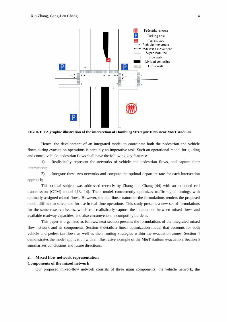
For example, if an evacuation operation for the M&T football stadium in the Baltimore downtown area is taking place (see Figure 1), the pedestrian will have to cross the streets to get to their parking lots or transit stops. Consequently, some conflicts between pedestrians and vehicle flows may incur in the evacuation zones. To minimize such potential conflicts, one firstly needs to identify the possible paths between each pedestrian O-D or vehicle O-D pair, and then provide the guidance for them to distribute among the possible paths. Since there are a large number of pedestrians to be evacuated, the conflict between these two types of flows needs to be properly guided during the evacuation process.
Xin Zhang, Gang-Len Chang 4
FIGURE 1 A graphic illustration of the intersection of Hamburg Street@MD295 near M&T stadium.
Hence, the development of an integrated model to coordinate both the pedestrian and vehicle
flows during evacuation operations is certainly an imperative task. Such an operational model for guiding and control vehicle-pedestrian flows shall have the following key features:
1) Realistically represent the networks of vehicle and pedestrian flows, and capture their interactions;
2) Integrate these two networks and compute the optimal departure rate for each intersection approach;
This critical subject was addressed recently by Zhang and Chang [44] with an extended cell transmission (CTM) model [13, 14]. Their model concurrently optimizes traffic signal timings with optimally assigned mixed flows. However, the non-linear nature of the formulations renders the proposed model difficult to solve, and for use in real-time operations. This study presents a new set of formulations for the same research issues, which can realistically capture the interactions between mixed flows and available roadway capacities, and also circumvents the computing burdens.
This paper is organized as follows: next section presents the formulations of the integrated mixed flow network and its components. Section 3 details a linear optimization model that accounts for both vehicle and pedestrian flows as well as their routing strategies within the evacuation zones. Section 4 demonstrates the model application with an illustrative example of the M&T stadium evacuation. Section 5 summarizes conclusions and future directions.
2. Mixed flow network representation Components of the mixed network Our proposed mixed-flow network consists of three main components: the vehicle network, the
Xin Zhang, Gang-Len Chang 5
pedestrian network, and interactions between them. For the vehicle network, we adopt the common unidirectional node-link concept, but use the bi-direction link-node notion for the pedestrian network. The flows in these two networks will interact via the connection and conflict nodes. The connection between the two networks is to convert the pedestrian flows to the vehicle flows. In reality, the connection usually takes place at parking areas and pick-up locations. The conflicts between these two flows usually occur at intersections or crossing areas.
Representation of the Vehicle Network
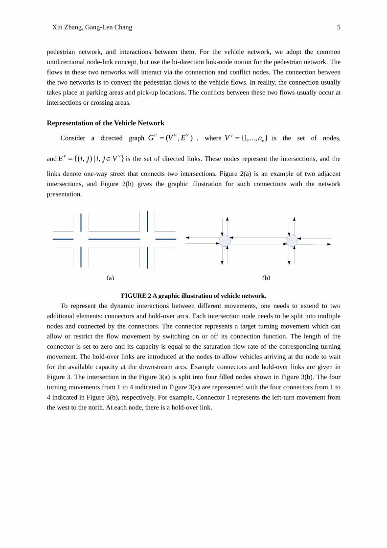
Consider a directed graph ( , )V V VG V E= , where {1,..., }vvV n= is the set of nodes,
and {( , ) | , }v vE i j i j V= ∈ is the set of directed links. These nodes represent the intersections, and the
links denote one-way street that connects two intersections. Figure 2(a) is an example of two adjacent intersections, and Figure 2(b) gives the graphic illustration for such connections with the network presentation.
FIGURE 2 A graphic illustration of vehicle network.
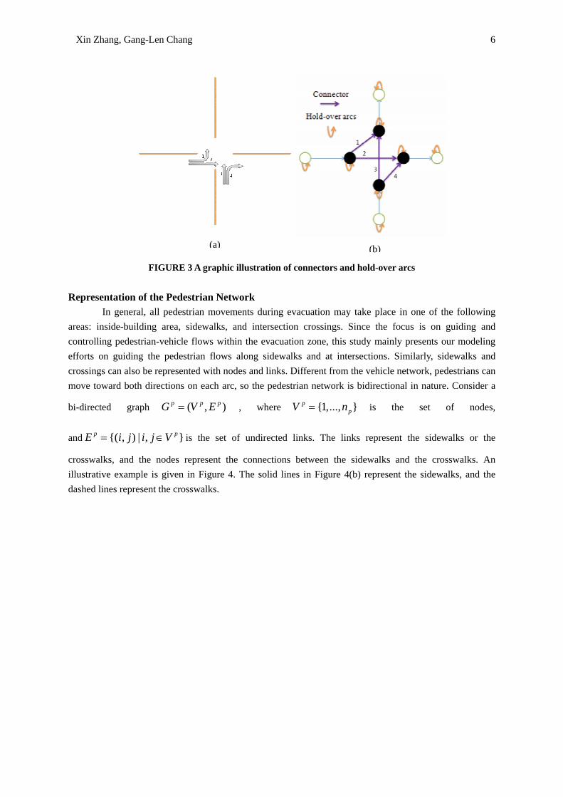
To represent the dynamic interactions between different movements, one needs to extend to two additional elements: connectors and hold-over arcs. Each intersection node needs to be split into multiple nodes and connected by the connectors. The connector represents a target turning movement which can allow or restrict the flow movement by switching on or off its connection function. The length of the connector is set to zero and its capacity is equal to the saturation flow rate of the corresponding turning movement. The hold-over links are introduced at the nodes to allow vehicles arriving at the node to wait for the available capacity at the downstream arcs. Example connectors and hold-over links are given in Figure 3. The intersection in the Figure 3(a) is split into four filled nodes shown in Figure 3(b). The four turning movements from 1 to 4 indicated in Figure 3(a) are represented with the four connectors from 1 to 4 indicated in Figure 3(b), respectively. For example, Connector 1 represents the left-turn movement from the west to the north. At each node, there is a hold-over link.
(a) (b)
Xin Zhang, Gang-Len Chang 6
FIGURE 3 A graphic illustration of connectors and hold-over arcs
Representation of the Pedestrian Network
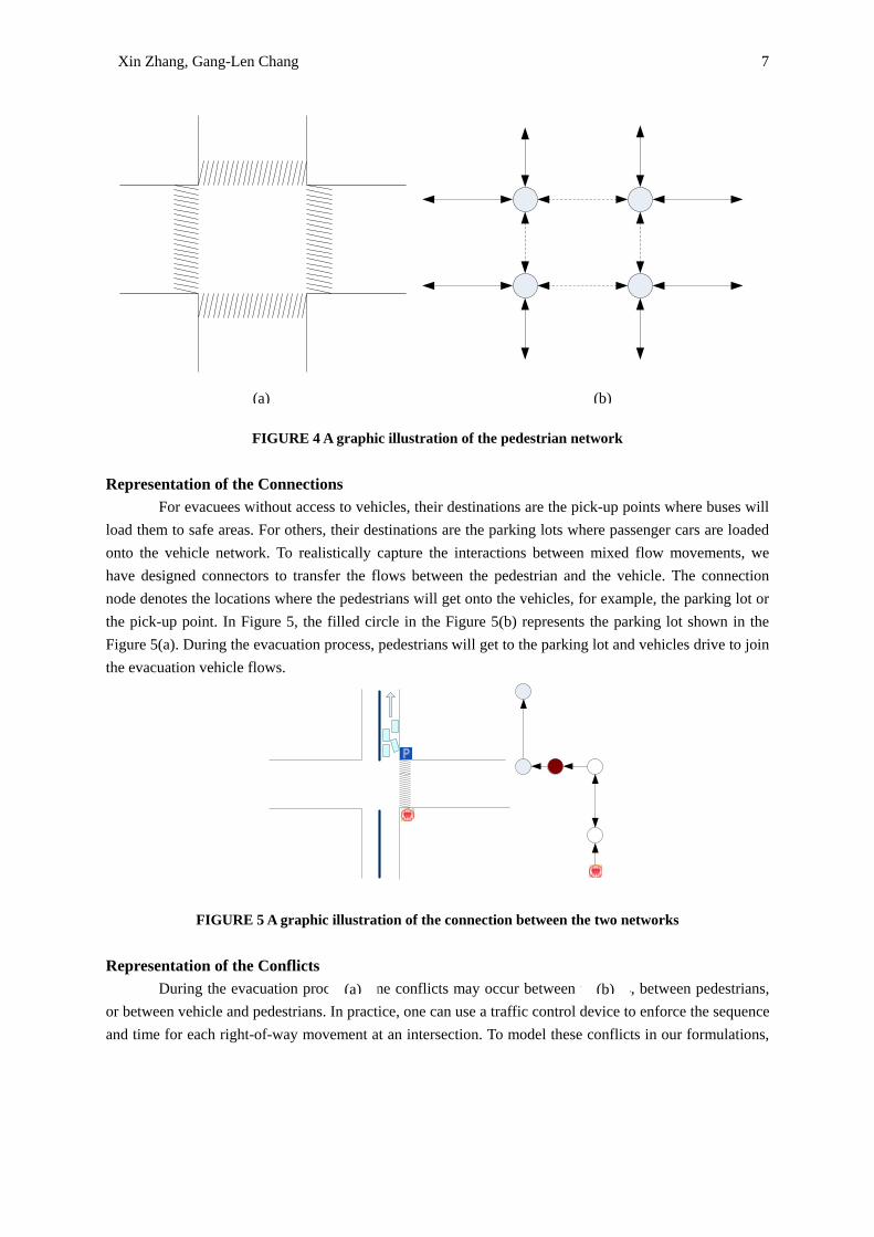
In general, all pedestrian movements during evacuation may take place in one of the following areas: inside-building area, sidewalks, and intersection crossings. Since the focus is on guiding and controlling pedestrian-vehicle flows within the evacuation zone, this study mainly presents our modeling efforts on guiding the pedestrian flows along sidewalks and at intersections. Similarly, sidewalks and crossings can also be represented with nodes and links. Different from the vehicle network, pedestrians can move toward both directions on each arc, so the pedestrian network is bidirectional in nature. Consider a
bi-directed graph ( , )p p pG V E= , where {1,..., }ppV n= is the set of nodes,
and {( , ) | , }p pE i j i j V= ∈ is the set of undirected links. The links represent the sidewalks or the
crosswalks, and the nodes represent the connections between the sidewalks and the crosswalks. An illustrative example is given in Figure 4. The solid lines in Figure 4(b) represent the sidewalks, and the dashed lines represent the crosswalks.
(a) (b)
Xin Zhang, Gang-Len Chang 7
FIGURE 4 A graphic illustration of the pedestrian network Representation of the Connections
For evacuees without access to vehicles, their destinations are the pick-up points where buses will load them to safe areas. For others, their destinations are the parking lots where passenger cars are loaded onto the vehicle network. To realistically capture the interactions between mixed flow movements, we have designed connectors to transfer the flows between the pedestrian and the vehicle. The connection node denotes the locations where the pedestrians will get onto the vehicles, for example, the parking lot or the pick-up point. In Figure 5, the filled circle in the Figure 5(b) represents the parking lot shown in the Figure 5(a). During the evacuation process, pedestrians will get to the parking lot and vehicles drive to join the evacuation vehicle flows.
FIGURE 5 A graphic illustration of the connection between the two networks Representation of the Conflicts
During the evacuation process, some conflicts may occur between vehicles, between pedestrians, or between vehicle and pedestrians. In practice, one can use a traffic control device to enforce the sequence and time for each right-of-way movement at an intersection. To model these conflicts in our formulations,
(a) (b)
(a) (b)
Xin Zhang, Gang-Len Chang 8
we define the following variable sets:
,p
i jC : The j -th pedestrian conflict set, consisting of conflicting pedestrian links at intersection i .
,vi jC : The j th vehicle conflict set, consisting of conflicting vehicle connectors at intersection i .
,i jC : The j -th conflict set, consisting of conflicting pedestrian links and vehicle connectors at
intersection i .
The pedestrian conflict set ,p
i jC is composed of pedestrian links representing crosswalks; and the
vehicle conflict set is composed of vehicle connectors representing turning movements at the i -th
intersection. The conflict set ,i jC is the union of sets ,p
i jC and ,vi jC . Any element in a valid set ,i jC , whether
it is a pedestrian link or a vehicle connector, is in conflict with any other elements in ,i jC . The same
property holds for ,p
i jC and ,vi jC .
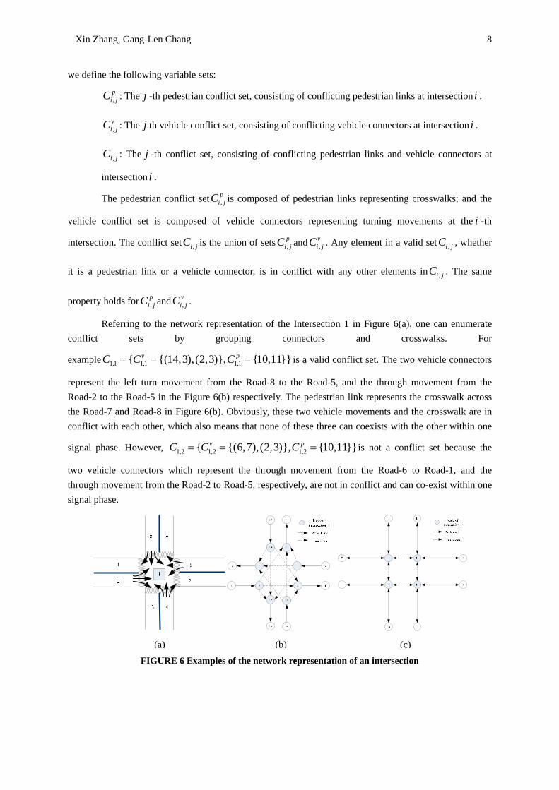
Referring to the network representation of the Intersection 1 in Figure 6(a), one can enumerate conflict sets by grouping connectors and crosswalks. For
example 1,1 1,1 1,1{ {(14,3),(2,3)}, {10,11}}v pC C C= = = is a valid conflict set. The two vehicle connectors
represent the left turn movement from the Road-8 to the Road-5, and the through movement from the Road-2 to the Road-5 in the Figure 6(b) respectively. The pedestrian link represents the crosswalk across the Road-7 and Road-8 in Figure 6(b). Obviously, these two vehicle movements and the crosswalk are in conflict with each other, which also means that none of these three can coexists with the other within one
signal phase. However, 1,2 1,2 1,2{ {(6,7),(2,3)}, {10,11}}v pC C C= = = is not a conflict set because the
two vehicle connectors which represent the through movement from the Road-6 to Road-1, and the through movement from the Road-2 to Road-5, respectively, are not in conflict and can co-exist within one signal phase.
FIGURE 6 Examples of the network representation of an intersection
(a) (b) (c)
Xin Zhang, Gang-Len Chang 9
3. Network-wide Mixed Flow Optimization Formulations
To maximize the evacuation flows during the response period, this study employs the maximum flow notion [45] to formulate the system-optimum flow distributions for the mixed traffic flows. The decision variables and given variables used are listed in the formulations below:
Decision variables:
,vi jx : The rate of vehicle flow that moves from node i to node j in the vehicle network
,pi jx : The rate of pedestrian flow that moves from node i to node j in the pedestrian network.
Known variables:
( ) :v i−Γ The set of vehicle nodes directed to a node i
( )v i+Γ : The set of vehicle nodes directed from a node i
( ) :p i−Γ The set of pedestrian nodes directed to a node i
( )p i+Γ : The set of pedestrian nodes directed from a node i
,vi jS : The saturation flow rate of the vehicle link ( , )i j
,p
i jS : The saturation flow rate of the pedestrian link ( , )i j
vE : The set of vehicle links in the vehicle network pE : The set of pedestrian links in the pedestrian network
vO : The set of origin nodes for vehicles
pO : The set of origin nodes for pedestrians
vD : The set of destination nodes for vehicles pD : The set of destination nodes for pedestrians
iλ : The carpooling rate for the connection node i
,p
i jC : The j th pedestrian conflict set consisting of conflicting pedestrian edges at intersection i .
,vi jC : The j th vehicle conflict set consisting of conflicting vehicle connectors at intersection i .
We can then formulate the entire network-wide mixed flow optimization problem as follows:
(P) Maximize: ,( )ppi ji O j i
x+∈ ∈Γ∑ ∑ ……………………………………………. (1)
Subject to:
Xin Zhang, Gang-Len Chang 10
, ,v vi j i jx S≤ , ( , ) vi j E∀ ∈ ……………………………………………………….. (2)
, , ,p p pi j j i i jx x S+ ≤ , ( , ) pi j E∀ ∈ ………………………………………………… (3)
, , 0v vi j j ij j
x x− =∑ ∑ , ( )v vi O D∀ ∉ ∪ …………………………………… (4)
, , 0p pi j j ij j
x x− =∑ ∑ , ( )p pi O D∀ ∉ ∪ …………………………………… (5)
,,
pj ijv
i jji
xx
λ=∑∑ , v pi O D∀ ∈ ∪ ………………………………………… (6)
, ,
, , ,
( , ) ( , ), ,
1v pk l k l
v p pi j i j j iv p
i j C i j Ci j i j
x x xS S∈ ∈
++ ≤∑ ∑ , k∀ ……………………………………… (7)
In our model, the objective is to evacuate as many evacuees as possible during a given time window, which is also the total pedestrian flow that reaches the final destinations. However, since it is a mixed-flow network, one can only acquire the total vehicle flow reaching the final. The objective function (1) seeks to maximize the total pedestrian flow that can be loaded onto the network. Constraints (2) and (3)
give the upper-bound of the vehicle and pedestrian flows, respectively. Since any pedestrian link ( , )i j is
bidirectional, the sum of the flows from both directions should not exceed the total capacity of that link. Constraints (4) and (5) are the flow conservation functions for the intermediate vehicle and pedestrian links, respectively. The constraint (6) converts the pedestrian flow to the vehicle flow. For different connection locations, i.e. parking garages or transit stops, the carpooling rate can vary with the vehicle type. The
constraint (7) deals with the conflicting movements. ,
,
vi jvi j
xS
or , ,
,
p pi j j i
pi j
x xS+
can be interpreted as the ratio of
time that the vehicle movement or the pedestrian crossing is allowed to have right-of-way or allowed to cross, which is similar to the concept of using green ratios for the signal controllers. Since at a given time point, any two vehicle movements or pedestrian links in a given conflict set can have only at most one allowed movement, the sum of the ratios should be no more than 1.
In the recent research by Zhang and Chang [50], the capacity reduction phenomenon caused by the frictions of oppositely moving pedestrians was modeled by introducing a capacity reduction parameter. In our model, the capacity drop phenomenon is not considered for the following two reasons:
(1) In emergency evacuation management process, uni-directional flows are more favored than bi-directional flows for maintaining the order and reducing the jamming possibility.
(2) Assuming pedestrians are subject to instructions during the evacuation process, the optimal routing strategy generated by our model will always be unidirectional
4. ILLUSTRATIVE EXAMPLE
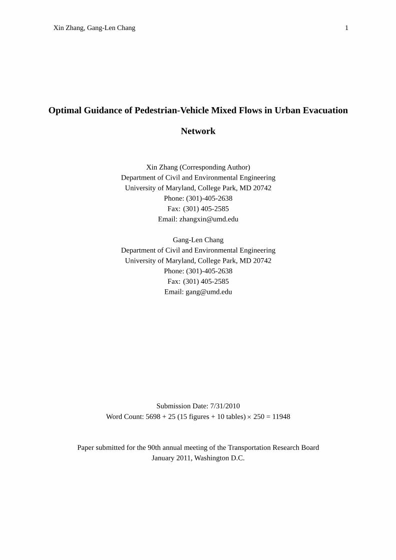
This section presents an illustrative case with the proposed model, using the M&T stadium in
Xin Zhang, Gang-Len Chang 11
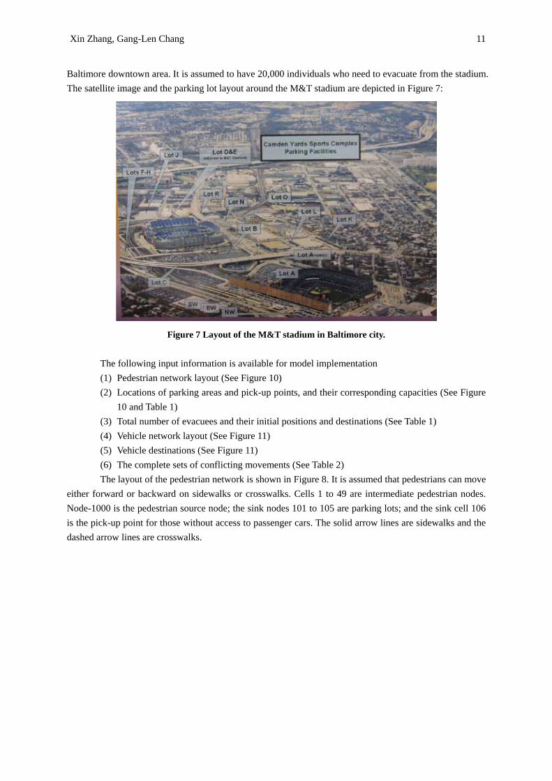
Baltimore downtown area. It is assumed to have 20,000 individuals who need to evacuate from the stadium. The satellite image and the parking lot layout around the M&T stadium are depicted in Figure 7:
Figure 7 Layout of the M&T stadium in Baltimore city.
The following input information is available for model implementation (1) Pedestrian network layout (See Figure 10) (2) Locations of parking areas and pick-up points, and their corresponding capacities (See Figure
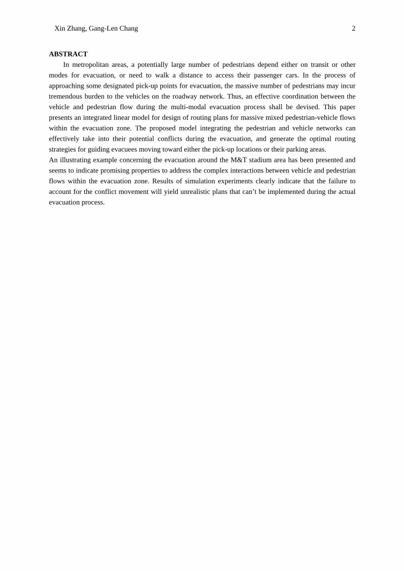
10 and Table 1) (3) Total number of evacuees and their initial positions and destinations (See Table 1) (4) Vehicle network layout (See Figure 11) (5) Vehicle destinations (See Figure 11) (6) The complete sets of conflicting movements (See Table 2) The layout of the pedestrian network is shown in Figure 8. It is assumed that pedestrians can move
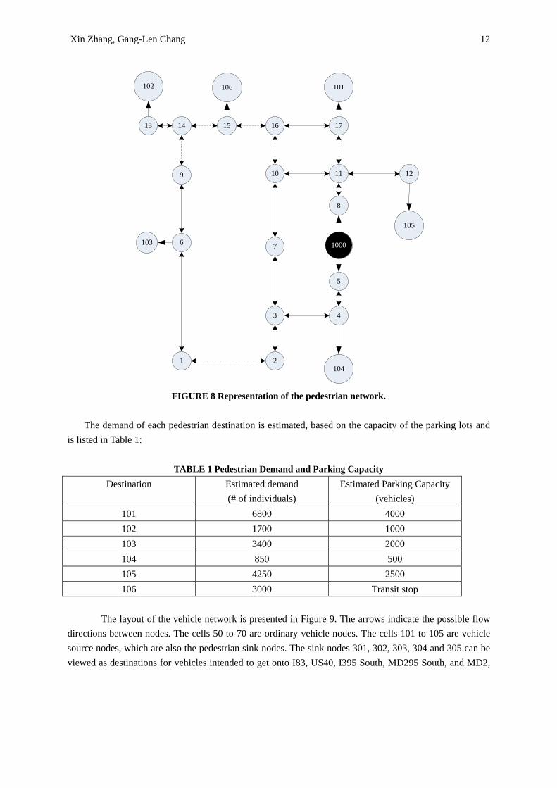
either forward or backward on sidewalks or crosswalks. Cells 1 to 49 are intermediate pedestrian nodes. Node-1000 is the pedestrian source node; the sink nodes 101 to 105 are parking lots; and the sink cell 106 is the pick-up point for those without access to passenger cars. The solid arrow lines are sidewalks and the dashed arrow lines are crosswalks.
Xin Zhang, Gang-Len Chang 12
1000
1041
103
2
3 4
5
6 7
8
9 10 11 12
105
101106102
13 14 15 16 17
FIGURE 8 Representation of the pedestrian network.
The demand of each pedestrian destination is estimated, based on the capacity of the parking lots and
is listed in Table 1:
TABLE 1 Pedestrian Demand and Parking Capacity Destination Estimated demand
(# of individuals) Estimated Parking Capacity
(vehicles) 101 6800 4000 102 1700 1000 103 3400 2000 104 850 500 105 4250 2500 106 3000 Transit stop
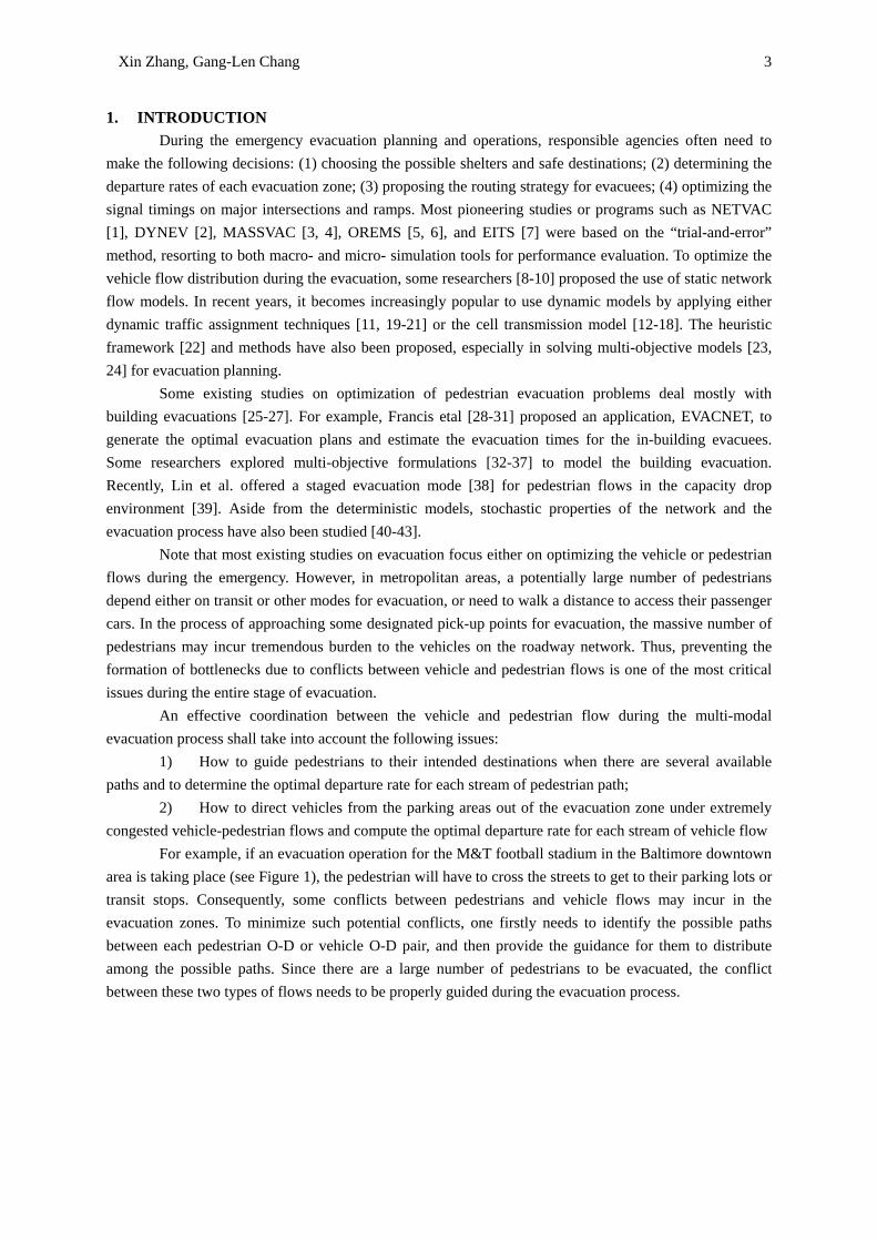
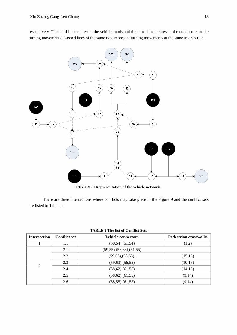
The layout of the vehicle network is presented in Figure 9. The arrows indicate the possible flow directions between nodes. The cells 50 to 70 are ordinary vehicle nodes. The cells 101 to 105 are vehicle source nodes, which are also the pedestrian sink nodes. The sink nodes 301, 302, 303, 304 and 305 can be viewed as destinations for vehicles intended to get onto I83, US40, I395 South, MD295 South, and MD2,
Xin Zhang, Gang-Len Chang 13
respectively. The solid lines represent the vehicle roads and the other lines represent the connectors or the turning movements. Dashed lines of the same type represent turning movements at the same intersection.
FIGURE 9 Representation of the vehicle network.
There are three intersections where conflicts may take place in the Figure 9 and the conflict sets
are listed in Table 2:
TABLE 2 The list of Conflict Sets
Intersection Conflict set Vehicle connectors Pedestrian crosswalks 1 1.1 (50,54),(51,54) (1,2)
2
2.1 (59,55),(56,63),(61,55) 2.2 (59,63),(56,63), (15,16) 2.3 (59,63),(56,55) (10,16) 2.4 (58,62),(61,55) (14,15) 2.5 (58,62),(61,55) (9,14) 2.6 (58,55),(61,55) (9,14)
Xin Zhang, Gang-Len Chang 14
3 3.1 (68,70), (65,70) 3.2 (68,64), (65,70)
The output of interest from implementing our model includes:
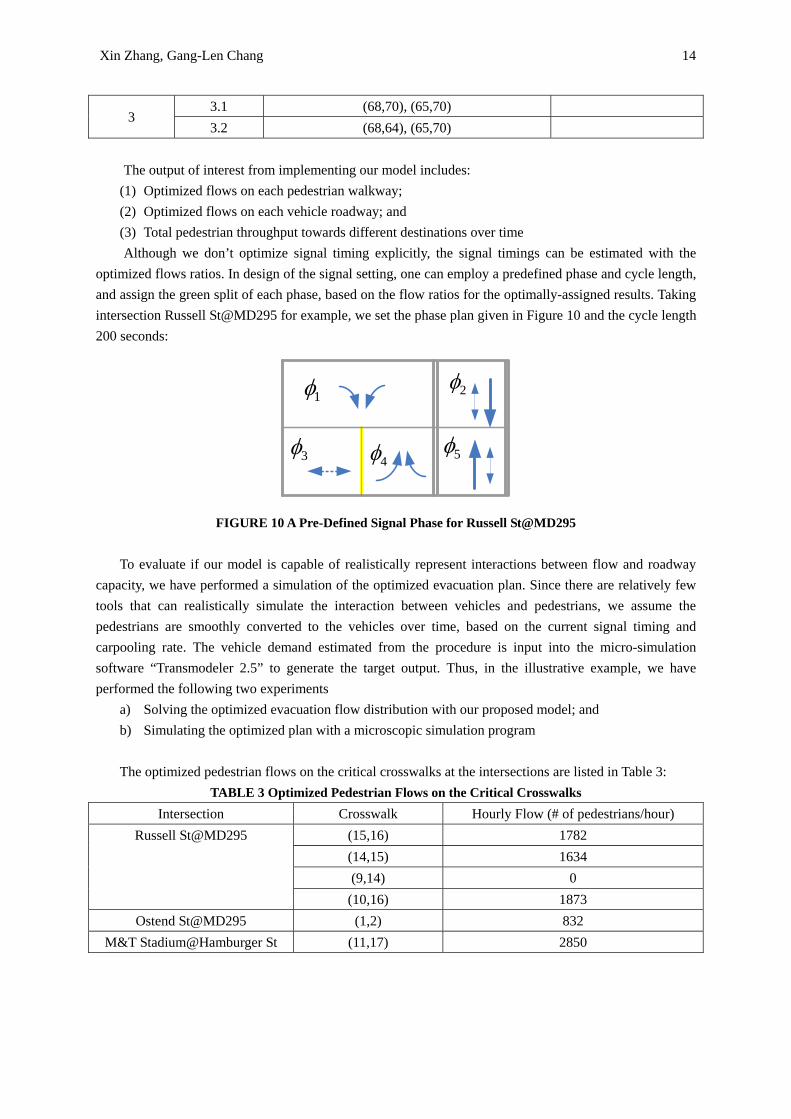
(1) Optimized flows on each pedestrian walkway; (2) Optimized flows on each vehicle roadway; and (3) Total pedestrian throughput towards different destinations over time Although we don’t optimize signal timing explicitly, the signal timings can be estimated with the
optimized flows ratios. In design of the signal setting, one can employ a predefined phase and cycle length, and assign the green split of each phase, based on the flow ratios for the optimally-assigned results. Taking intersection Russell St@MD295 for example, we set the phase plan given in Figure 10 and the cycle length 200 seconds:
1φ
3φ
2φ
4φ 5φ
FIGURE 10 A Pre-Defined Signal Phase for Russell St@MD295
To evaluate if our model is capable of realistically represent interactions between flow and roadway capacity, we have performed a simulation of the optimized evacuation plan. Since there are relatively few tools that can realistically simulate the interaction between vehicles and pedestrians, we assume the pedestrians are smoothly converted to the vehicles over time, based on the current signal timing and carpooling rate. The vehicle demand estimated from the procedure is input into the micro-simulation software “Transmodeler 2.5” to generate the target output. Thus, in the illustrative example, we have performed the following two experiments
a) Solving the optimized evacuation flow distribution with our proposed model; and b) Simulating the optimized plan with a microscopic simulation program
The optimized pedestrian flows on the critical crosswalks at the intersections are listed in Table 3:
TABLE 3 Optimized Pedestrian Flows on the Critical Crosswalks Intersection Crosswalk Hourly Flow (# of pedestrians/hour)
Russell St@MD295 (15,16) 1782 (14,15) 1634 (9,14) 0
(10,16) 1873 Ostend St@MD295 (1,2) 832
M&T Stadium@Hamburger St (11,17) 2850
Xin Zhang, Gang-Len Chang 15
The optimized vehicle flows on the critical roads are listed in Table 4:
TABLE 4 Optimized Vehicle Flows on the Critical Roads Road Name Vehicle Link Hourly Flow (# of vehicles/hour)
MD295 North (62,65) 596
(70,301) 1174
MD295 South (64,61) 654
(55,304) 1124 N MLK Blvd (66,302) 878 S MLK Blvd (67,303) 859
W Lee St (69,68) 1209 Hamburg St West (60,59) 1011 Hamburg St East (57,58) 1012 Ostend St East (103,50) 597
Ostend St West (52,51) 604
(53,305) 1200
The pedestrian flows obtained from the simulation output are listed in Table 5 below: TABLE 5 Simulated Pedestrian Flows on the Critical Crosswalks
Intersection Crosswalk Hourly Flow (# of pedestrians/hour) Russell St@MD295 (15,16) 1721
(14,15) 1670 (9,14) 0
(10,16) 1782 Ostend St@MD295 (1,2) 789
M&T Stadium@Hamburger St (11,17) 2711
The vehicle flows obtained from the simulation output are listed in Table 6 below: TABLE 6 Simulated Vehicle Flows on the Critical Roads
Road Name Vehicle Link Hourly Flow (# of vehicles/hour)
MD295 North (62,65) 581
(70,301) 1123
MD295 South (64,61) 601
(55,304) 1089 N MLK Blvd (66,302) 821 S MLK Blvd (67,303) 860
W Lee St (69,68) 1101 Hamburg St West (60,59) 992 Hamburg St East (57,58) 1003 Ostend St East (103,50) 530
Xin Zhang, Gang-Len Chang 16
Ostend St West (52,51) 593
(53,305) 1187
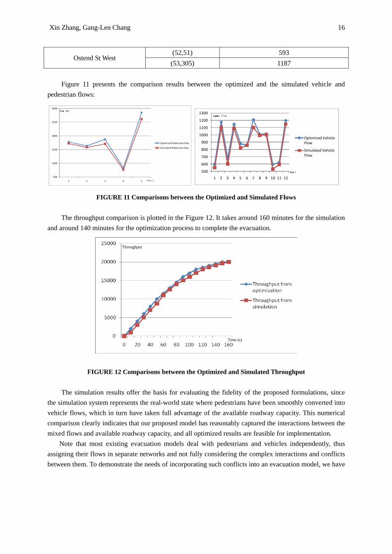
Figure 11 presents the comparison results between the optimized and the simulated vehicle and pedestrian flows:
500
1000
1500
2000
2500
3000
1 2 3 4 5
Optimized Pedestrian Flow
Simulated Pedestrian Flow
500
600
700
800
900
1000
1100
1200
1300
1 2 3 4 5 6 7 8 9 10 11 12
Optimized Vehicle Flow
Simulated Vehicle Flow
FIGURE 11 Comparisons between the Optimized and Simulated Flows
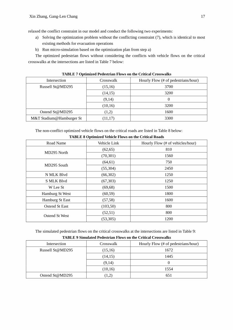
The throughput comparison is plotted in the Figure 12. It takes around 160 minutes for the simulation and around 140 minutes for the optimization process to complete the evacuation.
Time (s)
Throughput
FIGURE 12 Comparisons between the Optimized and Simulated Throughput
The simulation results offer the basis for evaluating the fidelity of the proposed formulations, since
the simulation system represents the real-world state where pedestrians have been smoothly converted into vehicle flows, which in turn have taken full advantage of the available roadway capacity. This numerical comparison clearly indicates that our proposed model has reasonably captured the interactions between the mixed flows and available roadway capacity, and all optimized results are feasible for implementation.
Note that most existing evacuation models deal with pedestrians and vehicles independently, thus assigning their flows in separate networks and not fully considering the complex interactions and conflicts between them. To demonstrate the needs of incorporating such conflicts into an evacuation model, we have
Xin Zhang, Gang-Len Chang 17
relaxed the conflict constraint in our model and conduct the following two experiments: a) Solving the optimization problem without the conflicting constraint (7), which is identical to most
existing methods for evacuation operations b) Run micro-simulation based on the optimization plan from step a) The optimized pedestrian flows without considering the conflicts with vehicle flows on the critical
crosswalks at the intersections are listed in Table 7 below:
TABLE 7 Optimized Pedestrian Flows on the Critical Crosswalks Intersection Crosswalk Hourly Flow (# of pedestrians/hour)
Russell St@MD295 (15,16) 3700 (14,15) 3200 (9,14) 0
(10,16) 3200 Ostend St@MD295 (1,2) 1600
M&T Stadium@Hamburger St (11,17) 3300
The non-conflict optimized vehicle flows on the critical roads are listed in Table 8 below: TABLE 8 Optimized Vehicle Flows on the Critical Roads
Road Name Vehicle Link Hourly Flow (# of vehicles/hour)
MD295 North (62,65) 810
(70,301) 1560
MD295 South (64,61) 750
(55,304) 2450 N MLK Blvd (66,302) 1250 S MLK Blvd (67,303) 1250
W Lee St (69,68) 1500 Hamburg St West (60,59) 1800 Hamburg St East (57,58) 1600 Ostend St East (103,50) 800
Ostend St West (52,51) 800
(53,305) 1200
The simulated pedestrian flows on the critical crosswalks at the intersections are listed in Table 9: TABLE 9 Simulated Pedestrian Flows on the Critical Crosswalks
Intersection Crosswalk Hourly Flow (# of pedestrians/hour) Russell St@MD295 (15,16) 1672
(14,15) 1445 (9,14) 0
(10,16) 1554 Ostend St@MD295 (1,2) 651
Xin Zhang, Gang-Len Chang 18
M&T Stadium@Hamburger St (11,17) 3276
The simulated vehicle flows on the critical are listed in Table 10 below: TABLE 10 Simulated Vehicle Flows on the Critical Roads
Road Name Vehicle Link Hourly Flow (# of vehicles/hour)
MD295 North (62,65) 632
(70,301) 1031
MD295 South (64,61) 521
(55,304) 1314 N MLK Blvd (66,302) 863 S MLK Blvd (67,303) 821
W Lee St (69,68) 1439 Hamburg St West (60,59) 972 Hamburg St East (57,58) 984 Ostend St East (103,50) 531
Ostend St West (52,51) 549
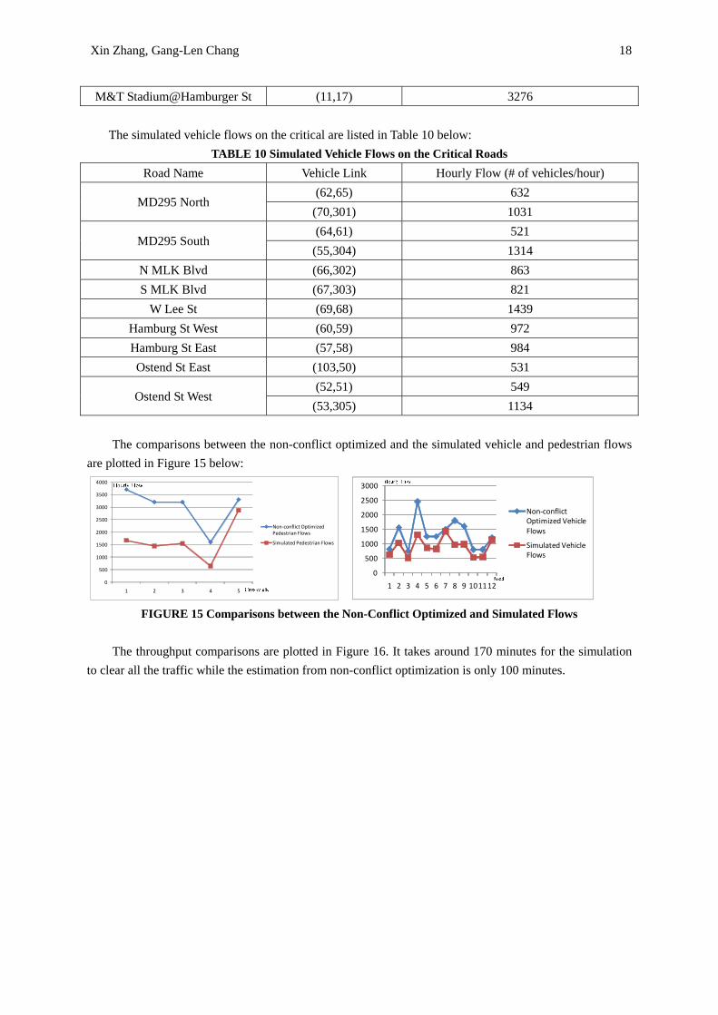
(53,305) 1134 The comparisons between the non-conflict optimized and the simulated vehicle and pedestrian flows
are plotted in Figure 15 below:
0
500
1000
1500
2000
2500
3000
3500
4000
1 2 3 4 5
Non‐conflict Optimized Pedestrian Flows
Simulated Pedestrian Flows
0
500
1000
1500
2000
2500
3000
1 2 3 4 5 6 7 8 9 101112
Non‐conflict Optimized Vehicle Flows
Simulated Vehicle Flows
FIGURE 15 Comparisons between the Non-Conflict Optimized and Simulated Flows
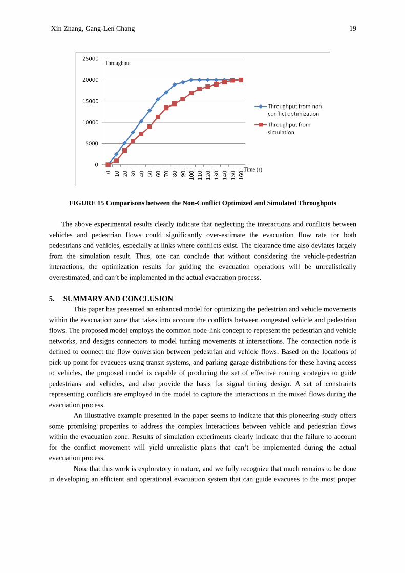
The throughput comparisons are plotted in Figure 16. It takes around 170 minutes for the simulation
to clear all the traffic while the estimation from non-conflict optimization is only 100 minutes.
Xin Zhang, Gang-Len Chang 19
Time (s)
Throughput
FIGURE 15 Comparisons between the Non-Conflict Optimized and Simulated Throughputs
The above experimental results clearly indicate that neglecting the interactions and conflicts between
vehicles and pedestrian flows could significantly over-estimate the evacuation flow rate for both pedestrians and vehicles, especially at links where conflicts exist. The clearance time also deviates largely from the simulation result. Thus, one can conclude that without considering the vehicle-pedestrian interactions, the optimization results for guiding the evacuation operations will be unrealistically overestimated, and can’t be implemented in the actual evacuation process. 5. SUMMARY AND CONCLUSION
This paper has presented an enhanced model for optimizing the pedestrian and vehicle movements within the evacuation zone that takes into account the conflicts between congested vehicle and pedestrian flows. The proposed model employs the common node-link concept to represent the pedestrian and vehicle networks, and designs connectors to model turning movements at intersections. The connection node is defined to connect the flow conversion between pedestrian and vehicle flows. Based on the locations of pick-up point for evacuees using transit systems, and parking garage distributions for these having access to vehicles, the proposed model is capable of producing the set of effective routing strategies to guide pedestrians and vehicles, and also provide the basis for signal timing design. A set of constraints representing conflicts are employed in the model to capture the interactions in the mixed flows during the evacuation process.
An illustrative example presented in the paper seems to indicate that this pioneering study offers some promising properties to address the complex interactions between vehicle and pedestrian flows within the evacuation zone. Results of simulation experiments clearly indicate that the failure to account for the conflict movement will yield unrealistic plans that can’t be implemented during the actual evacuation process.
Note that this work is exploratory in nature, and we fully recognize that much remains to be done in developing an efficient and operational evacuation system that can guide evacuees to the most proper
Xin Zhang, Gang-Len Chang 20
mode and direct various types of traffic flows to the most efficient routes. Our ongoing research along this line is to explore the dynamic nature of the evacuation process, and develop a dynamic model for generating routing strategies, based on the time-varying demand. Optimized signal designs along with pedestrian phases under emergencies scenarios are also our on-going research subjects. 6. References [1]. Sheffi, Y., H. Mahmassani, and W. B. Powell, A Transportation Network Evacuation Model, Transportation Research A, Volume 16, No. 3, 1982, pp. 209-218 [2]. Anon (1984) Formulations of the DYNEV and I-DYNEV Traffic Simulation Models Used in ESF, Federal Emergency Management Agency, Washington DC. [3]. Hobeika, A. G. and Jamei B. (1985) MASSVAC: A Model for Calculating Evacuation Time Under Natural Disasters, in Computer Simulation in Emergency Planning, Society of Computer Simulation, La Jolla, CA, [4]. Hobeika, A. G., Radwan, A. E., Jamei B. and Sivasailam, D. Transportation Actions to Reduce Evacuation Times Under Hurricane/Flood Conditions: A Case Study of Virginia Beach City. Presented at the Annual Meeting of the Transportation Research Board, January 2005 [5]. Anon (1999) Oak Ridge Evacuation Modeling System (OREMS) User Guide. Oak Ridge National Laboratory, Oak Ridge, TN. [6]. Anon (2000) Southeast United States Hurricane Evacuation Traffic Study: Evacuation Travel Demand Forecasting System. Technical Memorandum 2, Final Report, PBS&J, Tallahassee, FL. [7]. Evacuation Travel Demand Forecasting System. In Southeast United States Hurricane Evacuation Traffic Study, Technical Memorandum 2 PBS&J, Feb. 2000 [8]. Dunn, C.E., Newton, D., 1992, Optimal Routes in GIS and Emergency Planning Applications, Area 24, 259-267 [9] Campos, V. B. G., da Silva, P.A.L., Netto, P.O.B., 2000. Evacuation Transportation Planning, A Method of Identifying Optimal Independent Routes. In: Surcharov, L.J. (Ed.), Proceedings of Urban Transport V: Urban Transport and the Environment for the 21st Century. WIT Press, Southampton, pp. 555-564 [10] Thomas J. Cova, Justin P. Johnson, A Network Flow Model for Lane-based Evacuation Routing, Transportation Research Part A 37 (2003) 579-604 [11] Sattayhatewa, P., and B. Ran. Developing a Dynamic Traffic Management Model for Nuclear Power Plan Evacuation. Presented at 79th Annual Meeting of the Transportation Research Board, Washington, D.C., 2000 [12] Athanasios K. Ziliaskopoulos, A Linear Programming Model for the Single Destination System Optimum Dynamic Traffic Assignment Problem, Transportation Science, Volume 34, No. 1, February 2000, pp37-49 [13] C. F. Daganzo, The Cell Transmission Model: A Simple Dynamic Representation of Highway Traffic Consistent with the Hydrodynamic Theory, Transportation Research Part B, Volume 28, pp269-287, 1994 [14] C. F. Daganzo, The Cell Transmission Model. II. Network Traffic, Transportation Research Part B, Volume 29, pp79-93, 1995 [15] Yi-Chang Chiu, Hong Zheng, Modeling No-Notice Mass Evacuation Using a Dynamic Traffic Flow Optimization Model, IIE Transactions 39, pp83-94, 2007 [16] Wei Shen, Yu Nie and H. M. Zhang, Dynamic Network Simplex Method for Designing Emergency
Xin Zhang, Gang-Len Chang 21
Evacuation Plans, Transportation Research Record: Journal of the Transportation Research Board, No. 2022, Transportation Research Board of the National Academies, Washington, D.C., 2007, pp. 83-93 [17] Liu, Y., X. Lai, and G.L.Chang, Two-level Integrated Optimization Model for Planning of Emergency Evacuation: Case Study of Ocean City, Maryland, Under Hurricane Evacuation, Presented at 84th Annual Meeting of the Transportation Research Board, Washington, D.C., 2006 [18] Ying Liu, Xiaorong Lai, Gang-Len Chang, Cell-based Network Optimization Model for Staged Evacuation Planning Under Emergencies, Transportation Research Record: Journal of the Transportation Research Board, No. 1964, Transportation Research Board of the National Academies, Washington, D.C., 2006, pp. 127-135 [19] Hayssam Sbayti, Hani. S. Mahmassani, Optimal Scheduling of Evacuation Operations, Transportation Research Record: Journal of the Transportation Research Board, No. 1964, Transportation Research Board of the National Academies, Washington, D.C., 2006, pp. 238-246 [20] Chen Yueming, Xiao Deyun, Emergency Evacuation Model and Algorithms, Journal of Transportation Systems Engineering and Information Technology, Volume 8, Issue 6, December 2008, pp 96-100 [21] Chen Yueming, Xiao Deyun, Real-time Traffic Management under Emergency Evacuation Based on Dynamic Traffic Assignment, Proceedings of the IEEE International Conference on Automation and Logistics, Qingdao, China, September 2008. [22] Abbas Mohasel Afshar, Ali Haghani, Heuristic Framework for Optimizing Hurricane Evacuation Operations, Transportation Research Record: Journal of the Transportation Research Board, No. 2089, Transportation Research Board of the National Academies, Washington, D.C., 2008, pp.9-17 [23] Yuanyuan, Dingwei Wang, Multi-Objective Path Selection Model and Algorithm for Emergency Evacuation, Proceedings of the IEEE, International Conference on Automation and Logistics, August 18-21, 2007, Jinan, China [24] Mohammad Saadatseresht, Ali mansourian, Mohammad Taleai, Evacuation Planning Using Multi-objective Evolutionary Optimization Approach, European Journal of Operational Research 198 (2009) 305-314 [25] R. L. Francis, A Simple Graphical Procedure to Estimate the Minimum Time to Evacuate a Building, Society of Fire Protection Engineers, Technology Report 1979-5, 1979, 14p [26] R. L. Francis, A ‘Uniformity Principle’ for Evacuation Route Allocation, Journal of Research of National Bureau of Standards 86 (September-October) (1981) 509-513 [27] L. G. Chalmet, R. L. Francis, Network Models for Building Evacuation, Management Science, Volume 28, No 1, January 1982, pp86-104 [28] R. L. Francis, A Negative Exponential Solution to An Evacuation Problem, Research Report, No. 84-86, National Bureau of Standards, Center for Fire Research, October 1984 [29] R. L. Francis, T. M. Kisko, Network Models for Building Evacuation: Development of Software System, Grant No. NB81NADA2057, 1984, 62p [30] R. L. Francis, T. M. Kisko, EVACNET+: A Computer Program to Determine Optimal Building Evacuation Plans, Fire Safety Journal 9 (1985) 211-220 [31] T. Kiosko, R. Francis, C. Nobel, EVACNET4 User’s Guide, University of Florida, http://www.ise.ufl.edu/kisko/files/evacnet/, 1998 [32] M. M. Kostreva, T. Getachew, Optimization models in fire egress analysis for residential buildings, in:
Xin Zhang, Gang-Len Chang 22
Fire Safety Science: Proceedings of the Third, International Symposium 1991, Elsevier Applied Science, 1991, pp. 805-814 [33] T. Getachew, An Algorithm for Multiple-Objective Path Optimization with Time Dependent Links, in: Proceedings of the 10th International Conference on Multi-criteria Decision Making, July 1992, p. 319-330 [34] T. Getachew, M. Kostreva, L. Lancaster, A Generalization of Dynamic Programming for Pareto Optimization in Dynamic Networks, RAIRO Operation Research 34 (2000) 27-47 [35] M. Wiecek, Multi-criteria Decision Making in Fire Egress Analysis, IFAC/IFORS Workshop on Support Systems for Decision and Negotiation (June) (1992) 285-290 [36] T. Wiecek, Approximation in Time-Dependent Multi-objective Path Planning, in: Proceedings of the 1992 IEEE International Conference on Systems, Man and Cybernetics, October 1992, pp. 861-866 [37] T. Wiecek, Time Dependency in Multiple-Objective Dynamic Programming, Journal of Mathematical Analysis and Applications 173 (1993) 289-307 [38] P. Lin, S. M. Lo, H. C. Huang, On the use of Multi-stage Time-varying Quickest Time Approach for Optimization of Evacuation Planning, Fire Safety Journal 43 (2008) 282-290 [39] Elvezia M. Cepolina, Phased Evacuation: An Optimization Model which Takes into Account the Capacity Drop Phenomenon in Pedestrian Flows. [40] J. M. Smith, D. Towsley, The use of Queuing Networks in the Evaluation of Egress From Buildings, Environment and Planning B 8 (1981) 125-139 [41] J. M. Smith, C. J. Karbowics, A K-Shortest Paths Routing Heuristic for Stochastic Network Evacuation Models, Engineering Optimization 7 (1984) 253-280 [42] J. M. Smith, K. Talebi, Stochastic Network Evacuation Models, Computers & Operations Research 12 (6) (1985) 559-577 [43] J. M. Smith, D. Bakuli, Resource Allocation in State Dependent Emergency Evacuation Networks, European Journal of Operation Research 89 (1996) 543-555 [44] Xin Zhang, G. L. Chang, Optimal control strategies for massive vehicular-pedestrian mixed flows in the evacuation zone, presented at the 89th transportation annual meeting of the Transportation Research Board, January 2010, Washington D.C. [45] Ford, L. R., Fulkerson, D. R., 1962, Flows in Networks, Princeton University Press, Princeton.