Embed Size (px)
Citation preview

International Journal of Electrical, Electronics and Data Communication, ISSN: 2320-2084 Volume-3, Issue-8, Aug.-2015
Optimal Voltage And Frequency Control Of A Microgrid System Using A Teaching-Learning Based Optimization (Tlbo)Algorithm 5
OPTIMAL VOLTAGE AND FREQUENCY CONTROL OF A MICROGRID SYSTEM USING A TEACHING-LEARNING BASED
OPTIMIZATION (TLBO) ALGORITHM
1MAHDI HEDAYATI, 2HOSSEIN ABBASI
1,2Department of Electrical & Electronic Engineering, Faculty of Mechatronics, Islamic Azad University, Karaj Branch, Karaj, Iran
E-mail: [email protected], [email protected] Abstract- The stability is an important topic to plan and manage the energy in the microgrids as the same as the conventional power systems. The voltage and frequency stability is one of the most important issues recently studied in microgrids. The objectives of this paper are the modelling and designing of the components and optimal controllers for the voltage and frequency control of the AC/DC hybrid microgrid under the different disturbances. Since the PI controllers have the advantages of simple structure and easy implementation, so they were designed and modeled in this paper. The teaching-learning based optimization (TLBO) algorithm is used to optimize the controllers’ parameters. According to the achieved results, the optimal PI controllers have a good performance in voltage and frequency control of the microgrid. IndexTerms- Frequency Control, Tlbo Algorithm, Microgrid, Pi Controller, Voltage Control. I. INTRODUCTION Nowadays most of electrical power is generated by the centralized power plants usually including large water turbines, fossil fuel combustion engines or nuclear reactors. Then, the generated power is transferred to the load centers through the most economic and effective way by the transmission lines. The centralized power generation has been used for several decades. However, there are defects in such systems, the reliability and power supply availability are the most important among them and also the long transmission lines make huge economic losses. Furthermore, given the fact that the infrastructure of the many power systems, has been used for a long time and their life is often the end, therefore they may not response to increasing electrical power requirements and their maintenance needs large financial budgets. As a result, the current power systems are usually operated around their full capacity. A blackout occurred in north east USA on August 2003 due to the overload made in a main transmission area, is a typical example for the above problems. Also, in many cases, from an environmental perspective, the construction of a new large-scale power plant may not be the suitable option and even if construction is decided, selection and preparation of its location will be introduced as real challenges. To solve these inevitable problems of the concentrated power systems, application of distributed generation (DG) units in distribution systems can be considered as one of several practical and effective solutions. This application will lead to the emergence of smaller distribution networks, called microgids [1]. In general, a microgrid is a collection of micro sources and loads often providing both electricity and heat to the local area [2]. In a microgrid, a customary requirement is installing an energy storage system.
Micro-generation and loads are controlled with energy storage and sophisticated control, so that at the point of coupling to the network, they appear as a single aggregate load or generator [2,3]. Microgrids can be operated in a parallel or standalone mode. In the parallel mode, micrgrid can absorb electrical power from the main grid or it can be fed depending on energy consumption and generation in microgridas well as its interactions with the electricity market. When the power supply quality is threatened due to the occurrence of any abnormality in the main grid, microgrid may be separated from the main grid and operated in island mode [4]. The loads can be divided into two categories: AC and DC loads. DC loads such as residential loads (hybrid electric vehicles (HEVs), light emitting diodes (LEDs) and ...) can be connected directly to the DC bus, while AC loads are connected to the AC bus. In an AC microgrid, DC loads are connected to the AC bus by AC/DC rectifiers and also DC resources must be converted to AC. While, in the DC microgrids, AC sources should be converted to DC and AC loads must also be connected to the DC bus by DC/AC inverters. Thus, because of the need to multiple reverse conversions, the efficiency is dramatically reduced in AC and DC microgrids. Therefore, to reduce energy losses due to remove the reverse conversions, the concept of an AC/DC hybrid microgrid is recommended. Briefly, the reasons for the importance of the voltage and frequency stability issues in microgrids can be stated as follows: 1. Most DG units are not suitable for direct feeding, so it must be connected to the grid by power electronic devices. The use of power electronics devices are led to problems in the design and operation of the microgrids, which make it necessary for the design of suitable controllers and suitable operation of microgrids in parallel mode, island and
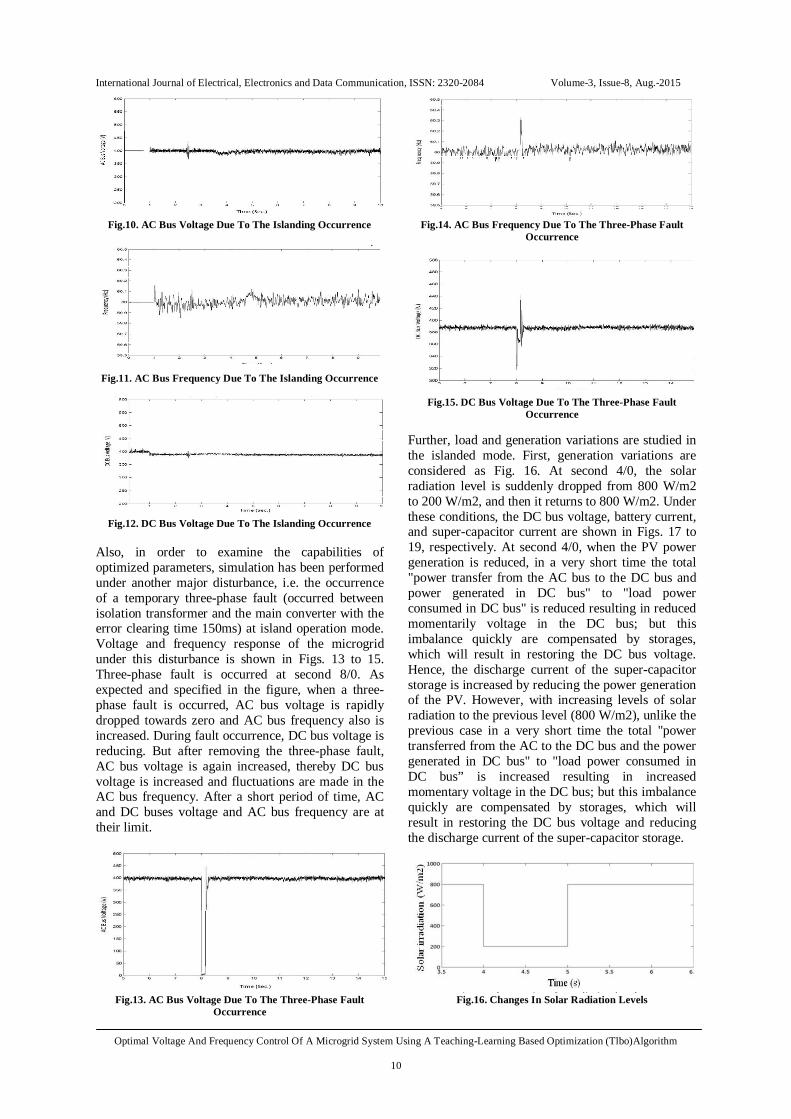
International Journal of Electrical, Electronics and Data Communication, ISSN: 2320-2084 Volume-3, Issue-8, Aug.-2015
Optimal Voltage And Frequency Control Of A Microgrid System Using A Teaching-Learning Based Optimization (Tlbo)Algorithm 6
state transition between these two modes of operation [5]. 2. Renewable energy sources such as wind and PV resources can be easily affected by environmental changes, which causes their output as varied and unpredictable. On the other hand, microgrids have a low inertia and small resources have small time constants, so that changes in wind speed, sunlight or consumed power in load can lead to reduce the stability or even make an islanded microgrid instable. 3. In addition to the above, other major factors affecting the microgrid stability include: control strategies of the distributed energy recourses (DERs), location of fault occurrence and inertia of the rotary motors and generators [5]. 4. Reduction in the efficiency and life of the equipment, such as residential loads, are other problems due to reduced or increased voltage in microgrids. Proportional-Integral (PI) controller is the most common controller used in industry and has been universally accepted in industrial control. The popularity of PI controllers can be attributed partly to their robust performance in a wide range of operating conditions and partly to their functional simplicity, which allows engineers to operate them in a simple, straightforward manner. This paper will introduce a teaching-learning based optimization (TLBO) algorithm to optimize parameters of PI controllers. TLBO algorithm is a global optimization method originally developed by Rao et al. [6-10]. It is a population- based iterative learning algorithm that exhibits some common characteristics with other evolutionary computation (EC) algorithms. However, TLBO searches for an optimum through each learner trying to achieve the experience of the teacher, which is treated as the most learned person in the society, thereby obtaining the optimum results, rather than through learners undergoing genetic operations like selection, crossover, and mutation [11]. Due to its simple concept and high efficiency, TLBO has become a very attractive optimization technique and has been successfully applied to many real world problems [6-10] and [12,13]. The main targets in this paper are: 1. In this paper, the focus will be on the control voltage of the microgrid and frequency control will be considered as one of the constraints on the problem. 2. Design and modeling of controllers are done to control the loads bus voltage. 3. Small disturbances (such as changes in power of the loads and generators) and large disturbances (such as a short circuit occurring on the network and transient state between two parallel and islanded operation modes) are considered to study the voltage stability of the proposed microgrid. 4. Optimization algorithm to optimize the parameters of (PI) controllers in the microgrid (in both parallel
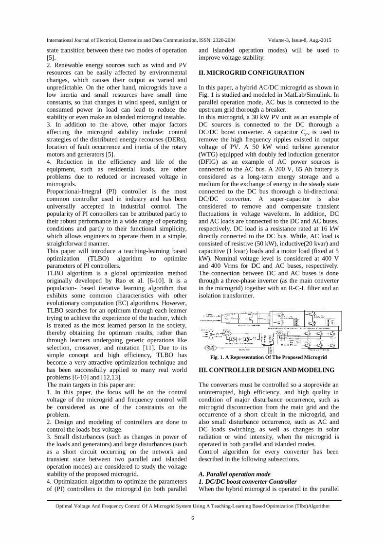
and islanded operation modes) will be used to improve voltage stability. II. MICROGRID CONFIGURATION In this paper, a hybrid AC/DC microgrid as shown in Fig. 1 is studied and modeled in MatLab/Simulink. In parallel operation mode, AC bus is connected to the upstream grid thorough a breaker. In this microgrid, a 30 kW PV unit as an example of DC sources is connected to the DC thorough a DC/DC boost converter. A capacitor Cpv is used to remove the high frequency ripples existed in output voltage of PV. A 50 kW wind turbine generator (WTG) equipped with doubly fed induction generator (DFIG) as an example of AC power sources is connected to the AC bus. A 200 V, 65 Ah battery is considered as a long-term energy storage and a medium for the exchange of energy in the steady state connected to the DC bus thorough a bi-directional DC/DC converter. A super-capacitor is also considered to remove and compensate transient fluctuations in voltage waveform. In addition, DC and AC loads are connected to the DC and AC buses, respectively. DC load is a resistance rated at 16 kW directly connected to the DC bus. While, AC load is consisted of resistive (50 kW), inductive(20 kvar) and capacitive (1 kvar) loads and a motor load (fixed at 5 kW). Nominal voltage level is considered at 400 V and 400 Vrms for DC and AC buses, respectively. The connection between DC and AC buses is done through a three-phase inverter (as the main converter in the microgrid) together with an R-C-L filter and an isolation transformer.
Fig. 1. A Representation Of The Proposed Microgrid
III. CONTROLLER DESIGN AND MODELING The converters must be controlled so a stoprovide an uninterrupted, high efficiency, and high quality in condition of major disturbance occurrence, such as microgrid disconnection from the main grid and the occurrence of a short circuit in the microgrid, and also small disturbance occurrence, such as AC and DC loads switching, as well as changes in solar radiation or wind intensity, when the microgrid is operated in both parallel and islanded modes. Control algorithm for every converter has been described in the following subsections. A. Parallel operation mode 1. DC/DC boost converter Controller When the hybrid microgrid is operated in the parallel

International Journal of Electrical, Electronics and Data Communication, ISSN: 2320-2084 Volume-3, Issue-8, Aug.-2015
Optimal Voltage And Frequency Control Of A Microgrid System Using A Teaching-Learning Based Optimization (Tlbo)Algorithm 7
mode, the objective of the PV boost converter control is maximum power point tracking(MPPT)by adjusting the terminal voltage. Here, the reference value for the terminal voltage of the solar panel Vpv
*is obtained by chaos algorithm(P & O),as shown in Fig.2[14,15]. Two-loop control for the DC/DC boost converter is described in [16]in which the control scheme objective is to provide a DC voltage with high quality and good dynamic response. This control scheme has been applied for PV systems to track the optimal terminal voltage through a MPPT algorithm with minor modifications, as shown in Fig.3. The outer voltage loop can track the reference voltage with zero steady-state error and internal control loop can improve the dynamic response[17]. One-cycle delay and saturation limiter in Fig. 3canhelpthe controller in tracking faster Vpv
*[17]. In steady state, i1-pre
*is in the linear region of the saturation limiter and is equal toi1
*. It can be seen that a step increase in Vpv
*will result in negativei1-pre
*, which in turn will lead i1*to zero
during the first transient period of the switching process. This reducesd1for pushing the average voltage Vd(1-d1) and Vpv to the reference value Vpv
*. 2. Battery and super-capacitor storage converter controller Storage battery has a high energy density, while the charging and discharging speed is relatively slow. But, super-capacitor storage has ability to quickly charge and discharge and consequently quickly compensate the voltage and frequency fluctuations. Therefore, super-capacitor is used to compensate high frequency fluctuations. Based on the characteristics of the battery and super-capacitor storages , a control scheme is used as shown in Fig. 4.
Fig. 2.MPPT Algorithm For PV Array
Fig.3. Block Diagram Of The Boost Converter Controller In
Parallel Operation Mode
Fig.4.Control Scheme Of The Hybrid Battery And Super-
Capacitor Storages In Parallel Operation Mode
In this scheme, the DC bus voltage is controlled by the battery and super-capacitor storages. Initially , DC bus voltage(vdc) is measured and compared to the reference voltage value (vdc_ref), then the result is sent to a PI controller to achieve a reference current iref. iref
is specified to twp parts: one part after passing through a low pass filter (LPF) and a coefficient y (now, ibatt
* is generated) is compared with ibatt and then sent to the PI controller to provide the PWM switching signal of battery converter. Also, another part after comparing iref, ibatt
*and isc is sent to the PI controllers to provide the PWM switching signal of super-capacitor converter. in this study, y and LPF cut-off frequency are selected in 0.95 and 50 Hz, respectively. 3. Main converter controller The aim of the main converter control scheme in a parallel mode is are active power generation predefined. Block diagram of the control scheme[17]has been proposed and shown in Fig.5. In addition, the active power transferred between DC and AC buses can be controlled by defining a specific value for the ifd
*. In this paper, the ifd*is equal to zero,
i.e.it is assumed that there are only reactive power exchange between DC and AC buses, but there is no active power exchange.
Fig.5.Blockdiagram Of The Main Converter Controller In The
Parallel Mode

International Journal of Electrical, Electronics and Data Communication, ISSN: 2320-2084 Volume-3, Issue-8, Aug.-2015
Optimal Voltage And Frequency Control Of A Microgrid System Using A Teaching-Learning Based Optimization (Tlbo)Algorithm 8
4. The DFIG converters controller A. Rotor-side converter controller The control process in DFIG uses this fact that the rotor current variation is reflected in stator current variation and hence, stator active and reactive power scan be controlled through the rotor current control. The rotor-side converter control objectives are MPPT in WTG and stator side reactive power management. Different control schemes such as direct torque control(DTC)and direct power control(DPC)for a DFIG in[18] and [19] have been proposed. In this paper, the proposed DTC scheme[17], shown in Fig.6, has been chosen as a control scheme for the rotor-side converter. B. Grid-side converter controller The task of the grid-side converter is to maintain a constant DC link voltage, regardless of the direction of power flow in the rotor. In this paper, the control scheme proposed in [20] was chosen for the grid-side converter shown in Fig. 7. In Fig.7, the symbol ε represents the variable in the reference system aligned with microgrid voltage.
Fig. 6.Dtccontrol Scheme For The Rotor-Side Converter Of DFIG In The Parallel Operation Mode
Fig.7. The Control Scheme Of The Grid-Side Converter In The
Parallel Operation Mode
C. Standal one operation mode In the standard one operation mode, the hybrid microgrid was isolated from the upstream network and is independently operated. In this mode, most controllers defined for the power electronic converters are the same as them in parallel operation mode, except that the main converter control scheme is changed which will be described later. In the standalone mode, the main converter is working as a voltage source to provide a stable voltage and frequency for the AC bus and soft transfer of the power between DC and AC buses. Multi-loop voltage control for a DC/AC inverter has been described in[21], in which the control scheme aims are to
provide a high quality AC voltage with good dynamic response at different load conditions. This control scheme can also be used in the standalone mode to control the main converter to provide a high quality AC voltage, with minor modifications as shown in Fig.8.
Fig.8. Control Block Diagram Of The Main Converter For The
Standalone
IV. TEACHING-LEARNING-BASED- OPTIMIZATION (TLBO) ALGORITHM One of the most recently developed metaheuristics is teaching-learning-based- optimization (TLBO) algorithm [22]. TLBO has many similarities to evolutionary algorithms (EAs): an initial population is randomly selected, moving on the way to the teacher and classmates is comparable to mutation operator in EA, and selection is based on comparing two solutions in which the better one always survives [23]. Similar to most other evolutionary optimization methods, TLBO is a population-based algorithm inspired by learning process in a classroom. The searching process consists of two phases, i.e. Teacher Phase and Learner Phase. In teacher phase, learners first get knowledge from a teacher and then from classmates in learner phase. In the entire population, the best solution is considered as the teacher (Xteacher). On the other hand, learners learn from the teacher in the teacher phase. In this phase, the teacher tries to enhance the results of other individuals (Xi) by increasing the mean result of the classroom (Xmean) towards his/her position Xteacher. In order to maintain stochastic features of the search, two randomly-generated parameters r and TF are applied in update formula for the solution Xi as: 푋 = 푋 + 푟. (푋 − 푇 .푋 ) (1) where is a randomly selected number in the range of 0 and 1 and TFis a teaching factor which can be either 1 or 2: 푇 = 푟표푢푛푑[1 + 푟푎푛푑(0,1){2− 1}] (2) Moreover, Xnew and Xi are the new and existing solution of i, [22 , 24]. In the second phase, i.e. the learner phase, the learners attempt to increase their information by interacting with others. Therefore, an individual learns new knowledge if the other individuals have more knowledge than him/her. Throughout this
International Journal of Electrical, Electronics and Data Communication, ISSN: 2320-2084 Volume-3, Issue-8, Aug.-2015
Optimal Voltage And Frequency Control Of A Microgrid System Using A Teaching-Learning Based Optimization (Tlbo)Algorithm 9
phase, the student Xi interacts randomly with another student Xj (i≠j) in order to improve his/her knowledge. In the case that Xj is better than Xi (i.e. f (Xj) <f(Xi) for minimization problems), Xi is moved toward Xj. Otherwise it is moved away from Xj:
푋 = 푋 + 푟. 푋 − 푋 푖푓푓(푋 ) > 푓 푋 푋 = 푋 + 푟. 푋 − 푋 푖푓푓(푋 ) < 푓 푋 (3)
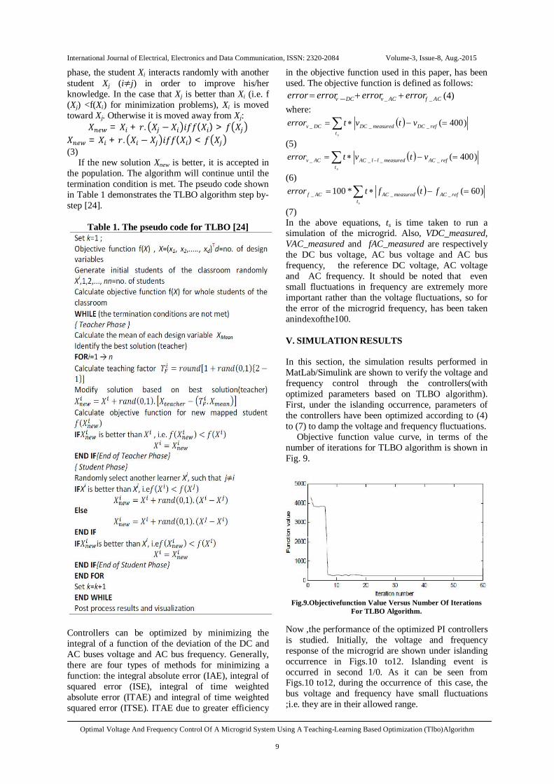
If the new solution Xnew is better, it is accepted in the population. The algorithm will continue until the termination condition is met. The pseudo code shown in Table 1 demonstrates the TLBO algorithm step by-step [24].
Table 1. The pseudo code for TLBO [24]
Controllers can be optimized by minimizing the integral of a function of the deviation of the DC and AC buses voltage and AC bus frequency. Generally, there are four types of methods for minimizing a function: the integral absolute error (IAE), integral of squared error (ISE), integral of time weighted absolute error (ITAE) and integral of time weighted squared error (ITSE). ITAE due to greater efficiency
in the objective function used in this paper, has been used. The objective function is defined as follows:
ACfACvDCv errorerrorerrorerror ___ (4) where:
st
refDCmeasuredDCDCv vtvterror )400(___
(5)
strefACmeasuredllACACv vtvterror )400(____
(6)
strefACmeasuredACACf ftfterror )60(*100 ___
(7) In the above equations, ts is time taken to run a simulation of the microgrid. Also, VDC_measured, VAC_measured and fAC_measured are respectively the DC bus voltage, AC bus voltage and AC bus frequency, the reference DC voltage, AC voltage and AC frequency. It should be noted that even small fluctuations in frequency are extremely more important rather than the voltage fluctuations, so for the error of the microgrid frequency, has been taken anindexofthe100. V. SIMULATION RESULTS In this section, the simulation results performed in MatLab/Simulink are shown to verify the voltage and frequency control through the controllers(with optimized parameters based on TLBO algorithm). First, under the islanding occurrence, parameters of the controllers have been optimized according to (4) to (7) to damp the voltage and frequency fluctuations.
Objective function value curve, in terms of the number of iterations for TLBO algorithm is shown in Fig. 9.
Fig.9.Objectivefunction Value Versus Number Of Iterations
For TLBO Algorithm. Now ,the performance of the optimized PI controllers is studied. Initially, the voltage and frequency response of the microgrid are shown under islanding occurrence in Figs.10 to12. Islanding event is occurred in second 1/0. As it can be seen from Figs.10 to12, during the occurrence of this case, the bus voltage and frequency have small fluctuations ;i.e. they are in their allowed range.
International Journal of Electrical, Electronics and Data Communication, ISSN: 2320-2084 Volume-3, Issue-8, Aug.-2015
Optimal Voltage And Frequency Control Of A Microgrid System Using A Teaching-Learning Based Optimization (Tlbo)Algorithm
10
Fig.10. AC Bus Voltage Due To The Islanding Occurrence
Fig.11. AC Bus Frequency Due To The Islanding Occurrence
Fig.12. DC Bus Voltage Due To The Islanding Occurrence
Also, in order to examine the capabilities of optimized parameters, simulation has been performed under another major disturbance, i.e. the occurrence of a temporary three-phase fault (occurred between isolation transformer and the main converter with the error clearing time 150ms) at island operation mode. Voltage and frequency response of the microgrid under this disturbance is shown in Figs. 13 to 15. Three-phase fault is occurred at second 8/0. As expected and specified in the figure, when a three-phase fault is occurred, AC bus voltage is rapidly dropped towards zero and AC bus frequency also is increased. During fault occurrence, DC bus voltage is reducing. But after removing the three-phase fault, AC bus voltage is again increased, thereby DC bus voltage is increased and fluctuations are made in the AC bus frequency. After a short period of time, AC and DC buses voltage and AC bus frequency are at their limit.
Fig.13. AC Bus Voltage Due To The Three-Phase Fault
Occurrence
Fig.14. AC Bus Frequency Due To The Three-Phase Fault
Occurrence
Fig.15. DC Bus Voltage Due To The Three-Phase Fault
Occurrence Further, load and generation variations are studied in the islanded mode. First, generation variations are considered as Fig. 16. At second 4/0, the solar radiation level is suddenly dropped from 800 W/m2 to 200 W/m2, and then it returns to 800 W/m2. Under these conditions, the DC bus voltage, battery current, and super-capacitor current are shown in Figs. 17 to 19, respectively. At second 4/0, when the PV power generation is reduced, in a very short time the total "power transfer from the AC bus to the DC bus and power generated in DC bus" to "load power consumed in DC bus" is reduced resulting in reduced momentarily voltage in the DC bus; but this imbalance quickly are compensated by storages, which will result in restoring the DC bus voltage. Hence, the discharge current of the super-capacitor storage is increased by reducing the power generation of the PV. However, with increasing levels of solar radiation to the previous level (800 W/m2), unlike the previous case in a very short time the total "power transferred from the AC to the DC bus and the power generated in DC bus" to "load power consumed in DC bus” is increased resulting in increased momentary voltage in the DC bus; but this imbalance quickly are compensated by storages, which will result in restoring the DC bus voltage and reducing the discharge current of the super-capacitor storage.
Fig.16. Changes In Solar Radiation Levels

International Journal of Electrical, Electronics and Data Communication, ISSN: 2320-2084 Volume-3, Issue-8, Aug.-2015
Optimal Voltage And Frequency Control Of A Microgrid System Using A Teaching-Learning Based Optimization (Tlbo)Algorithm
11
Fig.17. DC Bus Voltage During Changes In Solar Radiation
Levels
Fig.18. Battery Current During Changes In Solar Radiation
Levels
Fig.19. Super-Capacitor Current During Changes In Solar
Radiation Levels Then, change in the value of the DC load is considered. In second 5/0, the DC load value has changed to the half (i.e. from 8 kW to 4 kW) and it returns to their initial value in second 7/0. Under these changes, the DC bus voltage, battery and super-capacitor currents are shown in Figs. 20 to 22, respectively. Due to the increased load "power transferred from the AC to the DC bus and power generated in DC bus" to "power consumed in DC bus" is reduced in a very short time which results in the reduced DC bus voltage. But soon this imbalance was compensated by storages. But when load power is decreased in second 7/0, the amount of "generated and transmitted power in DC bus" to "power consumed in DC bus" is momentarily increased. This imbalance will quickly be compensated and DC bus voltage will also be restored.
Fig.20. DC Bus Voltage Due To The DC Load Variation
Fig.21. Battery current due to the DC load
variation
Fig.22. Super-Capacitor Current Due To The DC Load
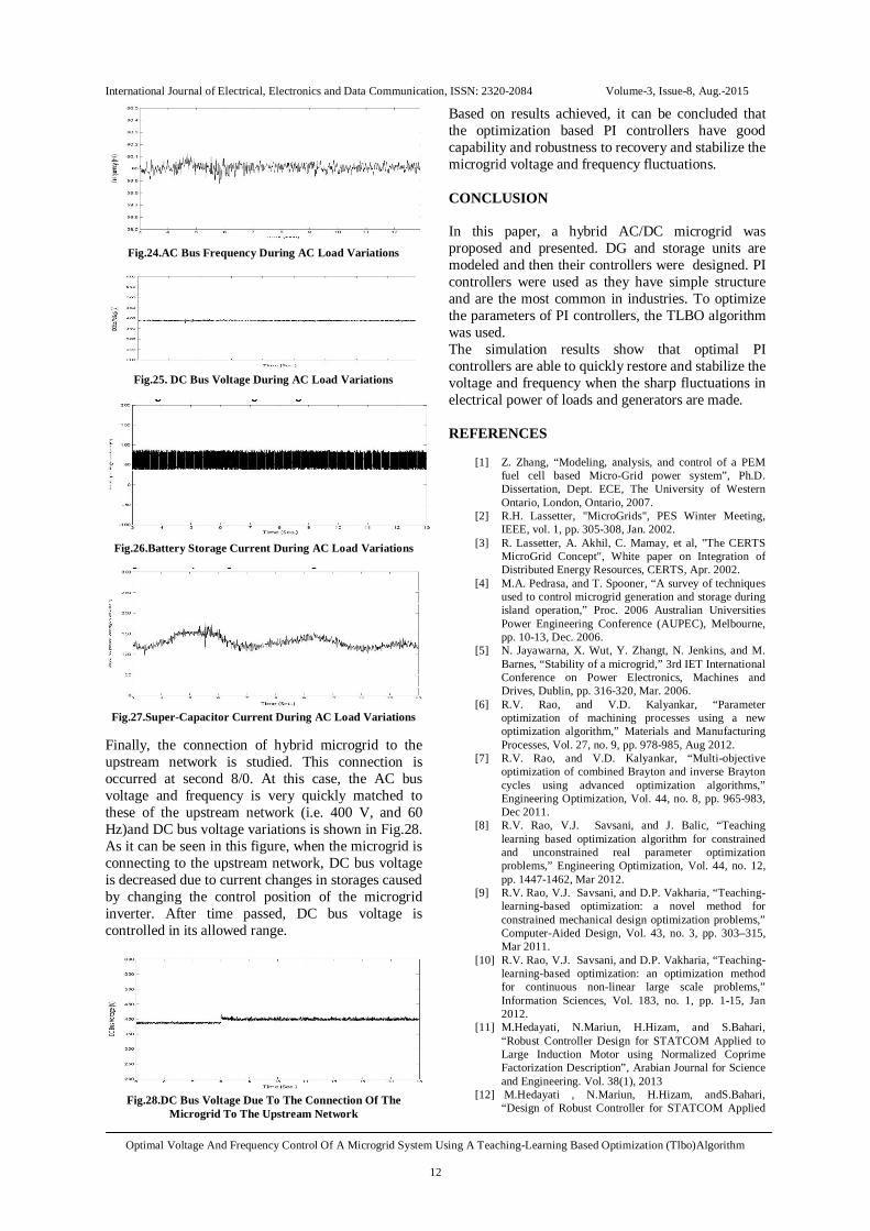
Variation In continue, the AC load variation is studied. In second 5/5, the AC load value is decreased from 50 kW to 25 kW and in second 6/5 it is returned to its initial value 50 kW. Under these variations, AC bus voltage, AC bus frequency, DC bus voltage, battery and super-capacitor storages current are shown in Figs. 23 to 27, respectively. As it can be seen, when AC load is reduced to the value 25 kW the "generated and transmitted power in the AC bus" to "load power consumed in AC bus" is increased and thereby the AC bus voltage and frequency is increased and DC bus voltage is also slightly increased. However, these changes also can be covered quickly by reducing the power generation of storages. Besides, when the load power is increased to 50 kW in AC bus, in a short time "total power transferred from the DC to AC bus and power generated in the AC bus" to "load power consumed at the AC bus" is reduced which in turn results in reducing the AC bus voltage and frequency. It should be noted that the reduction of AC voltage will affect on the DC bus voltage and slightly reduce it. But these fluctuations are quickly compensated by the storage generation.
Fig. 23.AC Bus Voltage During AC Load Variations
International Journal of Electrical, Electronics and Data Communication, ISSN: 2320-2084 Volume-3, Issue-8, Aug.-2015
Optimal Voltage And Frequency Control Of A Microgrid System Using A Teaching-Learning Based Optimization (Tlbo)Algorithm
12
Fig.24.AC Bus Frequency During AC Load Variations
Fig.25. DC Bus Voltage During AC Load Variations
Fig.26.Battery Storage Current During AC Load Variations
Fig.27.Super-Capacitor Current During AC Load Variations
Finally, the connection of hybrid microgrid to the upstream network is studied. This connection is occurred at second 8/0. At this case, the AC bus voltage and frequency is very quickly matched to these of the upstream network (i.e. 400 V, and 60 Hz)and DC bus voltage variations is shown in Fig.28. As it can be seen in this figure, when the microgrid is connecting to the upstream network, DC bus voltage is decreased due to current changes in storages caused by changing the control position of the microgrid inverter. After time passed, DC bus voltage is controlled in its allowed range.
Fig.28.DC Bus Voltage Due To The Connection Of The
Microgrid To The Upstream Network
Based on results achieved, it can be concluded that the optimization based PI controllers have good capability and robustness to recovery and stabilize the microgrid voltage and frequency fluctuations. CONCLUSION In this paper, a hybrid AC/DC microgrid was proposed and presented. DG and storage units are modeled and then their controllers were designed. PI controllers were used as they have simple structure and are the most common in industries. To optimize the parameters of PI controllers, the TLBO algorithm was used. The simulation results show that optimal PI controllers are able to quickly restore and stabilize the voltage and frequency when the sharp fluctuations in electrical power of loads and generators are made. REFERENCES
[1] Z. Zhang, “Modeling, analysis, and control of a PEM fuel cell based Micro-Grid power system”, Ph.D. Dissertation, Dept. ECE, The University of Western Ontario, London, Ontario, 2007.
[2] R.H. Lassetter, "MicroGrids", PES Winter Meeting, IEEE, vol. 1, pp. 305-308, Jan. 2002.
[3] R. Lassetter, A. Akhil, C. Mamay, et al, "The CERTS MicroGrid Concept", White paper on Integration of Distributed Energy Resources, CERTS, Apr. 2002.
[4] M.A. Pedrasa, and T. Spooner, “A survey of techniques used to control microgrid generation and storage during island operation,” Proc. 2006 Australian Universities Power Engineering Conference (AUPEC), Melbourne, pp. 10-13, Dec. 2006.
[5] N. Jayawarna, X. Wut, Y. Zhangt, N. Jenkins, and M. Barnes, “Stability of a microgrid,” 3rd IET International Conference on Power Electronics, Machines and Drives, Dublin, pp. 316-320, Mar. 2006.
[6] R.V. Rao, and V.D. Kalyankar, “Parameter optimization of machining processes using a new optimization algorithm,” Materials and Manufacturing Processes, Vol. 27, no. 9, pp. 978-985, Aug 2012.
[7] R.V. Rao, and V.D. Kalyankar, “Multi-objective optimization of combined Brayton and inverse Brayton cycles using advanced optimization algorithms,” Engineering Optimization, Vol. 44, no. 8, pp. 965-983, Dec 2011.
[8] R.V. Rao, V.J. Savsani, and J. Balic, “Teaching learning based optimization algorithm for constrained and unconstrained real parameter optimization problems,” Engineering Optimization, Vol. 44, no. 12, pp. 1447-1462, Mar 2012.
[9] R.V. Rao, V.J. Savsani, and D.P. Vakharia, “Teaching-learning-based optimization: a novel method for constrained mechanical design optimization problems,” Computer-Aided Design, Vol. 43, no. 3, pp. 303–315, Mar 2011.
[10] R.V. Rao, V.J. Savsani, and D.P. Vakharia, “Teaching-learning-based optimization: an optimization method for continuous non-linear large scale problems,” Information Sciences, Vol. 183, no. 1, pp. 1-15, Jan 2012.
[11] M.Hedayati, N.Mariun, H.Hizam, and S.Bahari, “Robust Controller Design for STATCOM Applied to Large Induction Motor using Normalized Coprime Factorization Description”, Arabian Journal for Science and Engineering. Vol. 38(1), 2013
[12] M.Hedayati , N.Mariun, H.Hizam, andS.Bahari, “Design of Robust Controller for STATCOM Applied

International Journal of Electrical, Electronics and Data Communication, ISSN: 2320-2084 Volume-3, Issue-8, Aug.-2015
Optimal Voltage And Frequency Control Of A Microgrid System Using A Teaching-Learning Based Optimization (Tlbo)Algorithm
13
to Large Induction Motor using Graphical Loop Shaping Method”, Journal of Electrical Engineering. Vol. 12(2), June 2012, pp. 192-200.
[13] Mahdi Hedayati, Norman Mariun," Assessment of Different Voltage Sags on Performance of Induction Motors operated with Shunt FACTS", 3rd IEEE Power Electrionics, Drive Systems and Technologies Conference (PEDSTC), Tehran, Iran, Feb 2012.
[14] Mahdi Hedayati, Norman Mariun, Hasim Hizam, Senan Mahmod Bashi, “Performance Study of Drive System and Shunt FACTS for the Operation of Induction Motors,” IEEE Symposium on Industrial Electronic and Applications (ISIEA), Penang, Malaysia, October 2010.
[15] C. Eberhart, and Yuhui Shi “Comparison between genetic algorithms and particle swarm optimization” in Proc. 7th Int. Conf. Evol. Program, LNCS 1447, pp 611–616, 1998.
[16] T. Vedat, “Design of planar steel frames using Teaching–Learning Based Optimization,” Engineering Structures,” vol 34, pp 225–232, 2011.
[17] S.C. Satapathy, and Anima Naik, “Data Clustering Based on Teaching-Learning Based Optimization,” Swarm, Evolutionary, and Memetic Computing, Lecture Notes in Computer Science, Vol. 7077, pp. 148-156, 2011.
[18] L.N. Khanh, J.-J. Seo, Y.-S. Kim, and D.-J. Won, “Power-management strategies for a grid-connected PV-FC hybrid system,” IEEE Transactions on Power Delivery, vol. 25, no. 3, pp. 1874-1882, Jul. 2010.
[19] R. Majumder, F. Shahnia, A. Ghosh, G. Ledwich, M. Wishart, and F. Zare, “Operation and control of a microgrid containing inertial and non-inertial micro sources,” IEEE Region 10 Conference (TENCON), Singapore, pp. 1-6, Jan. 2009.
[20] B. Bryantand, and M.K. Kazimierczuk, “Voltage loop of boost PWM DC-DC converters with peak current-mode control,” IEEE Transactions on Circuits Systems I, Reg. Papers, vol. 53, no. 1, pp. 99-105, Jan. 2006.
[21] X. Liu, P. Wang, and P.C. Loh, “A hybrid AC/DC microgrid and its coordination control,” IEEE Transactions on Smart Grid, vol. 2, no. 2, pp. 278-286, Jun. 2011.
[22] B. Dong, Y. Li, Z. Zheng, and L.Xu, “Control Strategies of Microgrid with Hybrid DC and AC Buses” Proceedings of the 2011-14th European Conference on Power Electronics and Applications (EPE 2011), Birmingham, pp. 1-8, Aug. 2011.
[23] S. Arnalte, J.C. Burgos, and J.L.R.-amenedo, “Direct torque control of a doubly-fed induction generator for variable speed wind turbines,” Journal of Electrical Power Components & Systems, vol. 30, no. 2, pp. 199–216, Feb. 2002.
[24] D.W. Zhiand, and L. Xu, “Direct power control of DFIG with constant switching frequency and improved transient performance,” IEEE Transactions on Energy Conversion, vol. 22, no. 1, pp. 110-118, Mar. 2007.
[25] L. Yang, Z. Xu, J. Østergaard, Z.Y. Dong, K.P. Wong, and X. Ma, “Oscillatory stability and eigenvalue sensitivity analysis of a DFIG wind turbine system,” IEEE Transactions on Energy Conversion, vol. 26, no. 1, pp. 328-339, Mar. 2011.
[26] M.N. Marwali, and A. Keyhani, “Control of distributed generation systems-Part I: Voltages and currents control,” IEEE Transactions on Power Electronics, vol. 19, no. 6, pp. 1541-1550, Nov. 2004.
[27] R. V.Rao, Savsani, V. J. &Vakharia, D. P., Teaching-learning-based optimization: An optimization method for continuous non-linear large scale problems. Information Sciences, Vol. 183, pp. 1-15, 2012.
[28] M.Crespinsek,., Liu, S. H. &Mernik, L., “A note on teaching-learning-based optimization algorithm. Information Sciences”, Vol. 212, pp. 79-93, 2012.
[29] A. Baghlani, and M.H. Makiabadi, “Teaching-Learning-Based Optimization Algorithm for Shape and Size Optimization of Truss Structures with Dynamic Frequency Constraints” IJST, Transactions of Civil Engineering, Vol. 37, No. C+, pp. 409-421, 2013.