Embed Size (px)
Citation preview

Optimisation of Reed Valves Dynamics by Means of Fluid Structure Interaction Modelling A. Angeletti, M.E. Biancolini *, E. Costa, M. Urbinati University of Rome Tor Vergata, Mechanical Engineering Department, Roma, Italy *corresponding author [email protected] ABSTRACT In this study the dynamic of a six petals reed valves pack is simulated accounting the complex fluid interaction phenomena occurring during transient flow of a typical working cycle of a two-stroke engines for go-kart competition. Starting from previous works on FSI (Fluid Structure Interaction) simulation for 2D cases and after the optimization of valve material considering only the structural 3D dynamic, this new step has been carried out thanks to a further development of a dedicated approach. Technically speaking, the proposed methodology consists in the use of FLUENT coupled with an embedded FSI tool based on a suite of UDF (User Defined Functions). This tool allows to generate a FEM structural model consistent with fluid mesh boundaries, to exchange information between FEM and CFD model (pressure and displacements through a weak approach on a time step basis or within the non-linear iteration), to solve the structural part adopting a general shell element type, and to account for contact non linearity. The coupled case definition is fully integrated in FLUENT by means of an user-friendly GUI and a TUI written in scheme language. The analysis of reed valve opening under steady boundary condition, considering the transient of fluid during valve opening, is presented. INTRODUCTION Although a reed valve seems to be a straightforward object, it is a complex component and the prediction of its behaviour represents a tricky task. For this reason, during last years, several investigations have been conducted and published in the scientific literature. Considering its basic function, the valve is a simple one-way system used to control the mass flow exchanged between two volumes characterised by a different pressure condition. The pressure gradient, acting on the surfaces of valve petals, promotes valve deformation and then the opening towards a prescribed direction with the consequent variation of the cross section. Because of this simple working principle, such type of automatic valve has become very attractive for several technical applications and, considering the peculiar objective of the present paper, it is widely used for fresh air charge in the crank case of two strokes engines. In fact, two strokes engines need a pressure charging during scavenging that can be obtained filling the volume of the crank-case with fresh fuel-air mixture during the compression strokes, and moving this charge in the cylinder thanks to the opening of inlet ports.
EASC 20094th European Automotive Simulation Conference
Munich, Germany6-7 July 2009
Copyright ANSYS, Inc.

The carter filling can be managed by means of a set of automatic reed valves that allow the entry of the fresh mixture only when the crankcase creates a precise suction. The high speed of the engine affects the dynamic of the opening and the closure of the valve; different valve opening profile is observed varying engine RPM and inlet conditions (usually controlled by means of a throttle valve). A typical configuration of the reed valves pack with six petals is shown in Figure 1. A rigid housing, usually wedge shaped, offers the support for the petals that are connected by means of bolts. The housing presents also six windows (usually of rectangular section with smooth edges) that are opened by the petals. The shape of the stop plate can be tuned to limit the opening of the petals or to promote a special shape of the open channel so as to optimise for crossing flow motion.
Fig. 1: Exploded view of a reed valves pack.
The shape of the assembly can be varied to optimise the air flow, changing the number of petals and the number of wedges. Typical solutions are shown in the picture sequence of Figure 2 that starts with the simpler one-petal solution and includes solution with up to eight petals. It is worthwhile to notice that asymmetric solutions can be used to deflect the flow to better fill the carter.
Fig. 2 A-B-C-D-E-F: Reed valves packs.
Building materials used for petals affect the dynamic response because of their great influence on reed flexibility and mass thus numerous materials have been adopted including composites made with glass or carbon fibres. The use of non metallic petals has a further benefit because limits the damage inflicted to the engine in the case of petal failure. In some applications, for instance, metallic stoppers are replaced with a reinforcement of the constraint region of petal by means of triangular component, as shown in Figure 3.
EASC 20094th European Automotive Simulation Conference
Munich, Germany6-7 July 2009
Copyright ANSYS, Inc.

Fig. 3: stiffeners used at the constraint point of petal. Several scientific contributions are present in the literature about fluid structure interaction and reed valve analysis. A short review can be found in [7]. A brief history of FSI in our research group is subsequently reported considering the most relevant steps. Our first interest in fluid structure modelling methods was born in 2002 with uncoupled dynamic study of a reed valve [1]. A FEM model has been proposed using the natural coordinates that, with respect to the modal ones, allow to easily account for contact non linearity. This simple model has been first coupled with a 1D gas-dynamic engine simulator [4] to successfully predict the performances of a secondary air injection system. Subsequently it was decided to couple the dynamic model with FLUENT for 2D analysis. An excellent agreement with experimental data has been observed and such FSI approach demonstrated to be feasible and very attractive for practical problems solution [2,3]. Meanwhile, it was decided to extend the approach to 3D cases developing a stand alone 3D code based on the theory of plates [5] which could take into account the effects of non isotropic materials orientation as well as the contact. In [6] others considerable results have been presented: a 3D coupled analysis has been tested to study the load response of a F1 front wing; the FEM solver Nastran has been used to generate stiffness and mass matrixes for the mesh extracted from FLUENT. All results related to 2D cases as well as the description of all theoretical details were finally collected in the previously cited paper [7]. The present paper has the aim to expose how the full fluid structure interaction (FSI) coupling method, already used for 2D studies of reed valves, has been extended to 3D cases coupling a generic shell behaviour to FLUENT solver. The novel simulation approach can be used as a powerful tool for the accurate design of reed valves. SOLID MODELLING OF AN ACTUAL REED VALVE SYSTEM The first step toward a complete 3D simulation of a reed valves pack is the precise CAD representation of the system. This step has been conducted using an actual part (the inlet of the engine Maxter 125 cc used for high performances go kart), its homologation fiches, and reverse engineering technique. All the components have modelled using SolidWorks software and a brief description of each one will follow. Ordering the components in the direction of the inlet we find: the carburettor, the diffuser, the reed valves pack and the primary inlet duct of the crankcase. It is interesting to notice how the last segment of the inlet is shaped to act also as a petal stopper. The carburettor is shown in Figure 4 only the wetted
EASC 20094th European Automotive Simulation Conference
Munich, Germany6-7 July 2009
Copyright ANSYS, Inc.

surface has been inserted in the model neglecting the valve body. The diffuser, shown in Figure 5, allows to gently deform the flux from the circular cross section of the carburettor to the rectangular section exposed by the reed valve pack. The reed valve housing, shown in Figure 6, splits the flow in the six windows that can be partially opened by the petal movements. The primary inlet duct of the crankcase has a twofold function: firstly, it defines the inlet duct shapes for the flow downstream to the six windows and, secondly, it acts as valve stopper accommodating the petal at full opening position.
Fig. 4: Solid model of the convergent cone of the carburettor.
Fig. 5: Solid model of the diffuser.
Fig. 6: Solid model of reed valves housing.
EASC 20094th European Automotive Simulation Conference
Munich, Germany6-7 July 2009
Copyright ANSYS, Inc.

Fig. 7: Solid model of the primary inlet duct of the crankcase.
Figure 8 shows the solid model of the complete assembly (on the left) as well as the reed petals (on the right). Since solid model has been built taking into account the requirements of CFD mesh generation rather than a simple CAD representation aimed at mechanical drawing, only wetted surfaces have been reproduced.
Fig. 8: Assembly of the inlet system controlled by the reeds valve.
FLUID STRUCTURE INTERACTION MODELLING FSI is a very interesting topic and its integrated resolution allows to tackle many physical problems that can be unlikely handled in different manner, namely using structural or fluid investigation separately. However, integrated solution of both problems is a difficult challenge, especially for numerical modelling where advanced solution strategies and tools are already well established for each of the two fields, but a standard and available mature approach for the coupled problem is still missing. Unfortunately, there are several cases in which the interaction between the fluid with adjoining structure, that governs the physical behaviour of the system. Some coupled problems can converge in a stable configuration, others can generate an oscillating solution, and some others can produce an unstable behaviour. The coupling technique used in the presented UDF is based on a weak approach according which the structural problem is solved after the fluid time computing. The forces applied to the structure are passed by FLUENT at the end of each time step to the FEM solver. Then the structural problem is solved and the new geometrical configuration is applied to the fluid domain by means of MDM (…) capability of FLUENT. The flow chart of the solution process is represented in Figure 9. This coupling strategy turns out to be very efficient and able to
EASC 20094th European Automotive Simulation Conference
Munich, Germany6-7 July 2009
Copyright ANSYS, Inc.

handle a wide range of FSI problems. Convergence is guarantee by choosing the correct time step size for the coupled problem.
Fig. 9: Coupling strategy for FSI simulation.
The external loads due to fluid pressure force, computed by means of the CFD solver, are passed to FEM solver that, after calculating the nodes structural displacements, returns this data to the CFD solver modifying its solution through the dynamic mesh regeneration of its deformable boundary. The current implementation of the presented FSI tool includes several options. A 2D version, available for linear problem, uses the implicit approach. Mass and Stiffness matrixes are generated at the beginning of the simulation and the solution is then iterated adopting a standard Newmark three steps scheme. Contact effect can be introduced as an external non linear load. A 2D non linear explicit version is available as well, and it is capable to handle large displacements (but small strains) and large rotations. The same options are also available for 3D, but currently limited to the special case of a flat rectangular shell. A generic 3D shell solver is also available, but it is currently limited to the linear problems. A generic shell of triangular elements can be handled. The original version was born using the FEM solver Nastran for the building of mass and stiffness matrixes and the current one includes also the formulation of a generic triangular shell element. Contact effects can still be managed introducing non linear loads. In the latter case, the coupling works for parallel simulations. Although FEM solver runs in serial, it can exchange information with the CFD mesh partitions of each calculation node. All the aforementioned solvers (with the exception of course of the explicit one) use a sparse representation of the matrixes and a high performances iterative solver.
EASC 20094th European Automotive Simulation Conference
Munich, Germany6-7 July 2009
Copyright ANSYS, Inc.
3D REED VALVE APPLICATION In the present paper the FSI approach is applied to a reed valve of a 125cc Go-kart engine interacting with a surrounding three dimensional flow field. The reed petals are made of fibreglass and their characteristics are collected in Table 1.
Material Glass fibre Density 1850 kg/m3 Young modulus 21.5⋅109 Pa Free length 29.0 mm Width 22.0 mm Thickness 0.46 mm Stopper radius 48.0 mm
Table 1: Reed petal material properties.
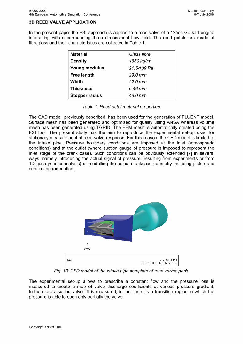
The CAD model, previously described, has been used for the generation of FLUENT model. Surface mesh has been generated and optimised for quality using ANSA whereas volume mesh has been generated using TGRID. The FEM mesh is automatically created using the FSI tool. The present study has the aim to reproduce the experimental set-up used for stationary measurement of reed valve response. For this reason, the CFD model is limited to the intake pipe. Pressure boundary conditions are imposed at the inlet (atmospheric conditions) and at the outlet (where suction gauge of pressure is imposed to represent the inlet stage of the crank case). Such conditions can be obviously extended [7] in several ways, namely introducing the actual signal of pressure (resulting from experiments or from 1D gas-dynamic analysis) or modelling the actual crankcase geometry including piston and connecting rod motion.
Fig. 10: CFD model of the intake pipe complete of reed valves pack.
The experimental set-up allows to prescribe a constant flow and the pressure loss is measured to create a map of valve discharge coefficients at various pressure gradient; furthermore also the valve lift is measured; in fact there is a transition region in which the pressure is able to open only partially the valve.
EASC 20094th European Automotive Simulation Conference
Munich, Germany6-7 July 2009
Copyright ANSYS, Inc.

The generation of FEM model is managed through FSI GUI that allows to the user to pick the deformable surface using the standard selection list of FLUENT; the same panel is used for the definition of material properties and of shell thickness as well as the specification of structural boundary conditions.
Fig. 11: FSI tool GUI panel.
Once all set-up data are correctly defined, FSI model can be initialized. This stage consists in the following steps:
• generation of FEM model; • generation of Dynamic matrixes; • connection between FEM model with CFD model.
The first step is accomplished using the connectivity of CFD mesh for the generation of triangular elements and grid nodes of FEM model. The FEM model is then completed extracting the information from the GUI panel that allows to define the material and the shell property of the element and the constraint conditions; the effect of gravity can also be accounted. In the second step the FEM model is solved using an external (the current version supports the Nastran format) or an internal solver. The solution stage is limited to the generation of stiffness matrix and mass matrix that are stored using the sparse format and combined to generate dynamic matrixes used for the solution (see [1] for further details about dynamic matrixes). It is vey important to notice that a quasi-static option can be used for coupling. In this case, only the stiffness matrix is generated and the dynamic response of the structure is neglected; this option can be used for steady analysis as well as for transient analysis in which the structural response is so fast that the dynamic imposed by the flow can be represented as a series of static response at the current load condition. In both cases, dynamic and quasi-static, the coupling between CFD and FEM can be finely tuned specifying the interaction time step (i.e. after that several CFD time steps are completed, at each complete CFD time step or within each iteration of a single time step) and relaxation
EASC 20094th European Automotive Simulation Conference
Munich, Germany6-7 July 2009
Copyright ANSYS, Inc.

coefficients to smooth the data exchanged in both directions (i.e. pressures used to excite the FEM and displacements to move the CFD mesh). The connection between node numbering of FEM and FLUENT is stored during the third initialization step because it will be used for data exchange between models. For this reason, direct and inverse connection pointers are stored to quickly exchange information between the structural solver and the CFD solver. Direct connection is used when the current FEM displacement filed is imposed to the CFD mesh whereas the inverse connection is used when the force loads (pressure and shear) acting on each elements of CFD boundary mesh are transformed in nodal forces and used to load the FEM model. The linking mechanism accounts for both sides of an immersed surface using the wall and its shadow. After initialization stage, the coupled simulation can be started. Typical results are shown in the following figures. The velocity field on the mid-plane of the pipe is reported in Figure 12 (on the left) where the pipe surfaces are represented in transparency; in the detail of Figure 12 (on the right) is clearly shown how the reed petals act as flow deflectors.
Fig. 12: Velocity field result in the mid plane of the intake pipe. The typical transient response of one of the valve petal tip is represented in the plot of Figure 13. The dynamic response is quite fast, the peak is observed after about 0.003 s and the response is stable after about 0.02 s. However, considering that two strokes engines work at very high speeds (for instance at 10000 RPM a cycle has a duration of about 0.006 s), it is quite clear the importance of the dynamic effect on reed valve motion.
EASC 20094th European Automotive Simulation Conference
Munich, Germany6-7 July 2009
Copyright ANSYS, Inc.

Fig. 13: Tip displacement of the upper central petal for a constant pressure gradient of
10.000 Pa. CONCLUSIONS An FSI tool capable to perform fluid structure interaction analysis within FLUENT has been presented for a practical application: the simulation of the working conditions of a pressure driven reed valve. The studies previously published by the authors for the 2D case has been extended to the 3D case. Only the first part of the research activities has been presented in this paper showing how the simulation tool is capable to recover the dynamic response of the system to constant prescribed pressure gradient. The ongoing activities include the modelling of a complete working cycle, accounting in this case for contact at the stop. Furthermore, an experimental equipment (shown in Figure 14) has been already prepared. A transparent part of the inlet pipe has been designed and built for the specific application, and it will be used in motored condition (even if a firing cycles can be studied after the check of material compatibility for local temperature) to acquire actual petal movements giving reference information for model validation and tuning.
Fig. 14 A-B: Transparent duct for optical observation of reed petals motion.
EASC 20094th European Automotive Simulation Conference
Munich, Germany6-7 July 2009
Copyright ANSYS, Inc.

REFERENCES [1] R. Baudille, M.E. Biancolini, “Dynamic analysis of a two stroke engine reed valve”, XXXI
AIAS Conference, Parma, Italy, 2002. [2] R. Baudille, M. E. Biancolini, “FSI Makes FLUENT More Flexible”, FLUENT News VOL
XIV – Spring 2005 Published by FLUENT Inc 10 Cavendish Court Lebanon, NH 03766 USA
[3] R. Baudille, M. E. Biancolini, “Modelling FSI problems in FLUENT: a dedicated approach by means of UDF programming”, Proceedings of the European Automotive CFD Conference, Frankfurt, Germany 2005.
[4] Battistoni M., Grimaldi C. N., Baudille R, Fiaccavento M. and Marcacci M., "Development of a Model for the Simulation of a Reed Valve Based Secondary Air Injection System for SI Engines", SAE Paper 2005-01-0224 – Proceedings of the 2005 SAE World Congress, April 11-14, 2005, Detroit, USA, edited by SAE International, Warrendale, PA, USA.
[5] R. Baudille, M. E. Biancolini, E. Mottola “Optimization of dynamic reed valve behaviour by material orientation” , XXXIV Convegno Nazionale dell’Associazione Italiana per l’Analisi delle Sollecitazioni (AIAS), Milano 14-17 Settembre 2005.
[6] M. E. Biancolini, R. Baudille, “Modelling FSI Problems in FLUENT: a General Purpose Approach by Means of UDF Programming”, Congresso FISITA 2006 F2006M235
[7] R. Baudille, M. E. Biancolini, “A general approach for studying the motion of a cantilever beam interacting with a 2D fluid flow” Interaction and Multiscale Mechanics, Vol. 1, No. 4 (2008) 000-000 1.
EASC 20094th European Automotive Simulation Conference
Munich, Germany6-7 July 2009
Copyright ANSYS, Inc.

EASC 20094th European Automotive Simulation Conference
Munich, Germany6-7 July 2009
Copyright ANSYS, Inc.