Embed Size (px)
Citation preview

Clink IIIntegrated Motor Control System
• Optimising plant performance, efficiency and productivity
• Simplex and redundant configuration possible
• Flexibility of communication protocols to higher level systems

2
To acquire the neccessary level of operational
information for appropriate management of today’s process,
oil & gas and chemical industries, optimum integration
between process and electrical controls is indispensable.
Eaton Holec’s integrated Clink system provides plant
managers with comprehensive data and opportunities to
further optimize plant performance, efficiency and
productivity. Over the past seven years, the Clink II has been
successfully applied in the renowned Capitole 40
Motor Control System of Eaton Holec. During this relatively
short period, Clink has been field-proven world-wide and
found full appreciation from customers in: Europe (food,
chemical, petrochemical industries, industrial buildings);
Middle East (oil & gas extraction, chemical industries);
The Far East (infrastructure, oil & gas extraction);
South America (oil refineries).
What is Clink? Clink is a microprocessor-based automation system with individualcontrol units for each motor and feeder circuit within a Capitole 40switchboard.All units execute an extensive range of protection, monitoring andcontrol functions. In addition, serial communication is possiblebetween the Motor Control Centre and other systems e.g.Distributed Control System (DCS), Supervisory Control And DataAcquisition System (SCADA) and Engineering Work Station (EWS).
Integration between process and electrical controls

3
Block diagram of system structureSCU = Starter Control UnitFCU = Feeder Control UnitLCU = Local Control UnitCIU 1 = Central Interface UnitCIU 2 = Redundant Central Interface UnitRCU = Remote Control Unit
= Redundant network
Note:Emergency shut down from the Remote Control Unit isalways possible irrespective and independent of Clink II.
What is Clink II?After a successful 5-year application period of Clink, aninnovated version Clink II has been introduced to meetfuture market requirements.Although the principle of protection has not beenchanged, a number of important alterations andadditions have been effectuated, viz.:• The flexibility of communication with ‘higher level’
systems (such as DCS, SCADA, etc.) has beenextended to Modbus, Profibus, Control Net, DataHighway Plus, Ethernet TCP/IP, etc.
• Due to growing safety requirements, processindustries demand an ever increasing degree ofsystem reliability and availability. For that reason,Clink II has now been equipped with a redundantcommunication link. However, for less demandingfields of application there is the opportunity to useClink II as a simplex system.
• For internal communication the open networkstandard DeviceNet is used. This has the advantagethat also frequency controllers, automatic transferswitching logic and other devices supportingDeviceNet can be simply implemented andconfigured via one and the same network.
System structureAs shown in the above diagram, three levels can bedistinguished:• Process control level
This level is usually governed by a DCS, a PLC or aSCADA system. The process controller controls theentire process, of which the control of motor drivesoften form an essential part.
• Switchgear levelOn this level the Clink II system, being an integralpart of the Capitole 40 Motor Control Centre,autonomously protects and monitors all motors andswitchgear. In addition, the SCU controls the motorstarter in accordance with process control demands.
• Field levelHere, the motors are situated, usually fitted with asafety switch for remote control. Emergency shutdown and/or motor control from the Remote ControlUnit - hard-wired to the motor starter - is possibleirrespective and independent of Clink II.
LCU
Field level
RCU
Process control level
Switchgearlevel
Monitoring, maintenance &engineering
Mfeeder/
incomer
DCS SCADA EWS
DeviceNet
CIU 1 CIU 2
SCU
SCU
SCU
FCU
FCU
FCU

4
Monitoring of operating data• Mains voltage• Motor current L1, L2, L3• Earth fault current• Motor temperature rise• Active power• Power factor• Status of contactor(s)• Energy measurement (kWh)
Monitoring of diagnostic and maintenance data• Number of operating hours• Number of contactor operations• Number of contactor operations during last hour• Starting current• Starting time• Trip current L1, L2, L3• Trip indication• Time to trip• Time to reset
SCU standard functionsMotor protection
• Thermal:- Stall- Motor overload
• Phase unbalance• Earth leakage• Process underload• Process overload• External protection
Motor control• Starter control for:
- Direct-on-line (single & 3-phase)- Star-delta- Forward - reverse- Dual speed
• Manual control, manual reset• Automatic restart after mains failure
Process Control Monitoring, Maintenance & Engineering
Clink II in Capitole 40
DeviceNet communication linkFast response and highlyreliable communication link,based on the CAN protocol.• Multi Master protocol• Powerful error handling
capability
Redundant DeviceNetcommunication link
Serial communicationlink to process controlCompatible protocols:• Modbus• ControlNet• Profibus• Data Highway Plus• Ethernet TCP/IP,
etc.
Redundant serial communication link to process control

5
ControlThe unit possesses 8 digital inputs and 8 digital outputsto indicate, e.g., the status of circuit breaker and switch-disconnector. In addition the module’s digital outputsenable functions such as closing or opening the circuitbreaker or resetting the circuit breaker after a trip.• Automatic restart after mains failure
Over/UnderThe Over/Under function determines whether the valuesof voltage, current and power have fallen below or haveexceeded the set level.
Min/MaxWith this function the maximum and minimum values of - Voltage- Current- Current demand- Active power- Reactive power- Apparent power- Active power demandcan be defined. To evaluate, for example, peak demandor minimum load over a new period of time the valuescan be reset.
FCU standard functionsMeasurement
• Voltage• Current• Power factor• Power• FrequencyFrom these measurements a great number ofvalues can be derived, such as:- Voltage between phases and between phase
and neutral (V)- Current through phases and neutral (A)- Current demand (A)- Active power (kW)- Active power demand (kW)- Reactive power (kVAr)- Apparent power (kVA)- Active energy import (kWh)- Active energy export (kWh)- Reactive energy import (kVArh)- Reactive energy export (kVArh)- Apparent energy (kVAh)
Protection• Earth leakage protection adjustable
Starter Control Unit (SCU)For protection, monitoringand control of motor starterunits.
Feeder Control Unit (FCU)For measurement andcontrol of incoming andoutgoing feeders.
Central Interface Unit (CIU)An interface which providesflexibility of communicationwith ‘higher level’ systems.
Local Control Unit (LCU)A user interface.
6
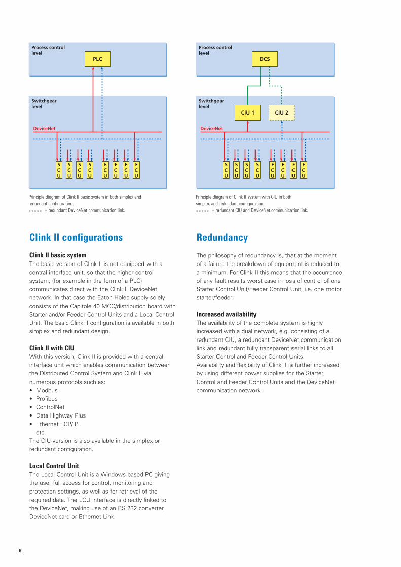
Clink II configurations
Clink II basic systemThe basic version of Clink II is not equipped with acentral interface unit, so that the higher controlsystem, (for example in the form of a PLC)communicates direct with the Clink II DeviceNetnetwork. In that case the Eaton Holec supply solelyconsists of the Capitole 40 MCC/distribution board withStarter and/or Feeder Control Units and a Local ControlUnit. The basic Clink II configuration is available in bothsimplex and redundant design.
Clink II with CIUWith this version, Clink II is provided with a centralinterface unit which enables communication betweenthe Distributed Control System and Clink II vianumerous protocols such as:• Modbus• Profibus• ControlNet• Data Highway Plus• Ethernet TCP/IP
etc.The CIU-version is also available in the simplex orredundant configuration.
Local Control UnitThe Local Control Unit is a Windows based PC givingthe user full access for control, monitoring andprotection settings, as well as for retrieval of therequired data. The LCU interface is directly linked tothe DeviceNet, making use of an RS 232 converter,DeviceNet card or Ethernet Link.
Redundancy
The philosophy of redundancy is, that at the momentof a failure the breakdown of equipment is reduced toa minimum. For Clink II this means that the occurrenceof any fault results worst case in loss of control of oneStarter Control Unit/Feeder Control Unit, i.e. one motorstarter/feeder.
Increased availabilityThe availability of the complete system is highlyincreased with a dual network, e.g. consisting of aredundant CIU, a redundant DeviceNet communicationlink and redundant fully transparent serial links to allStarter Control and Feeder Control Units.Availability and flexibility of Clink II is further increasedby using different power supplies for the StarterControl and Feeder Control Units and the DeviceNetcommunication network.
Process control level
Switchgearlevel
PLC
DeviceNet
SCU
SCU
SCU
FCU
FCU
FCU
SCU
FCU
Process control level
Switchgearlevel
DCS
DeviceNet
CIU 1 CIU 2
SCU
SCU
SCU
FCU
FCU
FCU
SCU
FCU
Principle diagram of Clink II basic system in both simplex and redundant configuration.
= redundant DeviceNet communication link.
Principle diagram of Clink II system with CIU in bothsimplex and redundant configuration.
= redundant CIU and DeviceNet communication link.

7
Other Eaton Holec deliveries
Besides Clink II and Capitole 40Besides Capitole 40 MCC/switchboards and Clink IIIntegrated Motor Control Systems Eaton Holecdelivers SCADA and EWS systems.
SCADA (Supervisory Control And DataAcquisition)From a supervisory point of view SCADA systemsare of a higher level than PLC systems, i.e. theycan control lower-level systems. For example, aSCADA system can give a starting command to apumping device. However, the most important taskof a SCADA system, the acquisition, is the retrievaland processing of data; processing in the sense ofa dynamic presentation on a display unit or thecreation of accounts or data files.
EWS (Engineering Work Stations)EWS (usually based on a PC) is often applied on(sub)station level. The system is coupled to theIntegrated Motor Control System and/or feederrelays by means of a serial link. With EWS it ispossible to verify or, if required, change theIMCS/feeder relay settings. Verification ofmeasured IMCS/feeder relay values is alsopossible.
LCU
Field level
RCU
Process control level
Switchgearlevel
Monitoring, maintenance &engineering
Mfeeder/incomer
DCS SCADA EWS
DeviceNet
CIU 1 CIU 2
SCU
SCU
SCU
FCU
FCU
FCU
= SCADA & EWS systems optional deliveries of Eaton Holec.

Eaton Industries (Netherlands) B.V.P.O. Box 237550 AA HengeloThe Netherlands
Tel.: +31 (0)74 - 246 40 10Fax: +31 (0)74 - 246 40 [email protected]
Due to continuous research and develop -ment policy Eaton reserves the right to makechanges in design and specifications of theproducts without prior written notice.
© 2011 Eaton CorporationAll rights reserved.
Form. 1993155G0101April 2011
Eaton's Electrical Sector is aglobal leader in powerdistribution, power quality,control and automation, andmonitoring products. Whencombined with Eaton's full-scaleengineering services, theseproducts provide customer-driven PowerChain™ solutionsto serve the power systemneeds of the data center,industrial, institutional, publicsector, utility, commercial,residential, IT, mission critical,alternative energy and OEMmarkets worldwide.
PowerChain™ solutions helpenterprises achieve sustainableand competitive advantagesthrough proactive managementof the power system as astrategic, integrated assetthroughout its life cycle,resulting in enhanced safety,greater reliability and energyefficiency. For more information,visit www.eaton.com/electrical.