Embed Size (px)
Citation preview

Optimization Assisted Concept Design of Aircraft Floor Structures
Wolfgang Machunze
09. November 2011

• Project scope
• Concept idea
• Using HyperWorks concept design phase of innovative PAX floor structure
Sub modelling technique
Free size optimization
Sizing of composite cross beam
Parameterisation of CAD models CATIA V5 - Hypermesh morphing
Shuffle optimization – Stacking rules
• Manufacturing of sized cross beam structure
• Pax floor design status
• Outlook
Optimization assisted concept design of aircraft floor structures
Page 2
14 November, 2011
Outline

Optimization assisted concept design of aircraft floor structures
Scope:
Pax floor within typical fuselage area of
reference A/C NGA
Concept targets:
• Weight saving
• Pax floor height reduction
• Modularization – pre equipped structures
• Low cost manufacturing
Pax floor design driver:
• Statics, dynamics
• Attachment points (seat rails, z-strut)
• System installation
Pax floor
A
A
Section cut A-A
Project scope
Page 3
14 November, 2011
Reference - CFRP Concept idea - CFRP
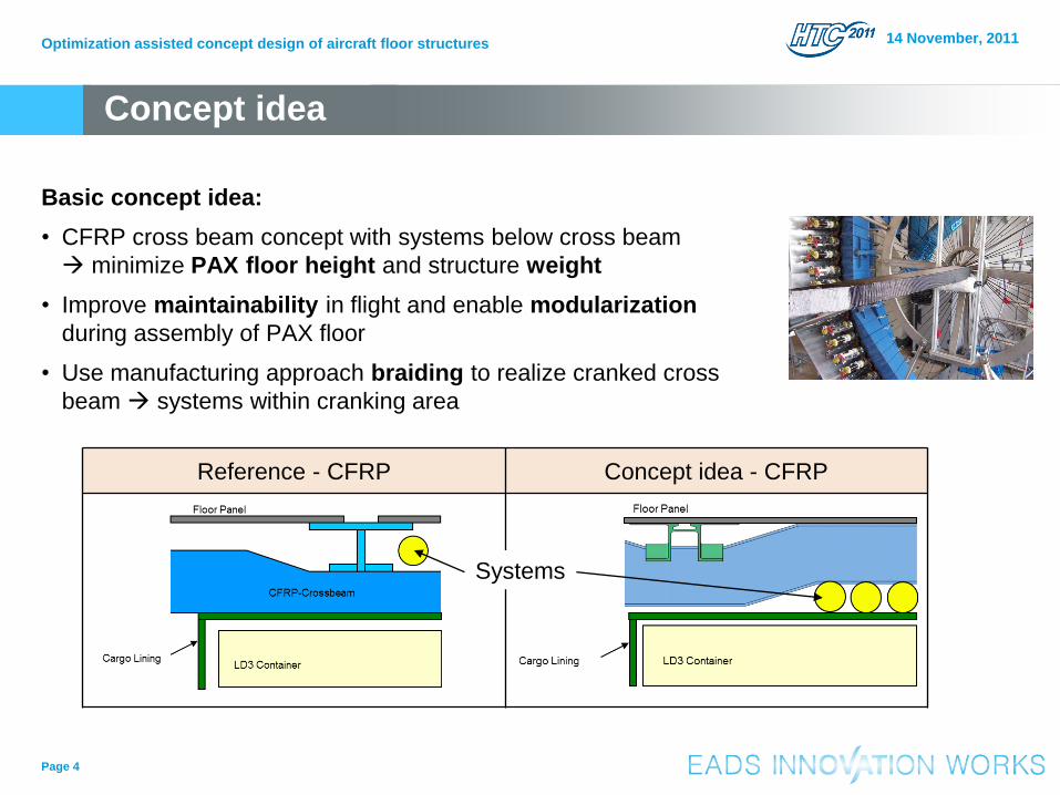
Basic concept idea:
• CFRP cross beam concept with systems below cross beam
minimize PAX floor height and structure weight
• Improve maintainability in flight and enable modularization
during assembly of PAX floor
• Use manufacturing approach braiding to realize cranked cross
beam systems within cranking area
Optimization assisted concept design of aircraft floor structures
Page 4
14 November, 2011
Concept idea
Systems

• Sizing of sub components within global aircraft FE-model with realistic surrounding loads,
stiffness and boundary conditions
• Reduction of simulation time by using superelement approach:
surrounding structure (red) represented by KAAX & PAX matrix
• Check of approach: Displacement for dimensioning load case of cross beam structure
“Rapid Recompression” (typical fuselage section 16/18)
Optimization assisted concept design of aircraft floor structures 14 November, 2011
Sub modelling technique
Global FE ISSY model Sub model with KAAX & PAX
Surrounding aircraft structure
Sub model for PAX floor sizing
Page 5

Optimization assisted concept design of aircraft floor structures
Page 6
14 November, 2011
Cross beam - dimensioning load cases
• 8 load cases considered within sizing
process for cross beam structure
Design mainly driven by bending loads
• Ground Loads
Symmetrical landing case
• Gust Loads
Continuous turbulences lateral
• Failure Loads
Rapid decompression up
Rapid decompression down
• Double inner pressure – tension loads
Symmetrical landing
Turbulence lateral
Rapid decompression down Rapid decompression up
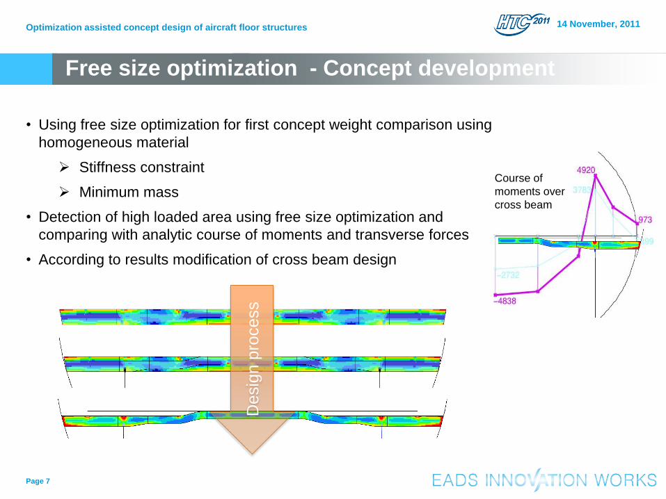
• Using free size optimization for first concept weight comparison using
homogeneous material
Stiffness constraint
Minimum mass
• Detection of high loaded area using free size optimization and
comparing with analytic course of moments and transverse forces
• According to results modification of cross beam design
Optimization assisted concept design of aircraft floor structures
Page 7
14 November, 2011
Free size optimization - Concept development
Course of
moments over
cross beam
De
sig
n p
rocess

Optimization assisted concept design of aircraft floor structures
Page 8
14 November, 2011
Sizing optimization
• CFRP sizing optimization considering manufacturing constraints with target robust design
• Span direction 4 varying areas with differing design variables
– By equations forced to minimized thickness steps within cross beam to reduce
manufacturing effort
– Crossbeam:

• Stiffness
• Stress
– Max-Stress criteria:
• Strain
– Evaluated via 2 equations:
• Stability
• Manufacturing constraints
• Laminate stacking rules
– Percentages to meet the rules in later shuffle optimization
Optimization assisted concept design of aircraft floor structures
Page 9
14 November, 2011
Sizing optimization - constraints Mid-point
LC 574 LC 576
Max. deflection
allowed [mm] + xx,xx mm - xx,xx mm
^
1c 1 ^
1t
2
12
2
1
00.000.0
1:
xxxx
IMA
Modes Eigenvalue range
15 0.05 < λ < 3
Y
Z

Shape Optimization – Shear centre
Force
Shape
• Consideration of shear centre within optimization
steps using design variables and equations
Prevent crossbeam twist
• PAX floor panel nodes from ISSY-model used for
load introduction node coordinates need to be
modified by actual shear centre
• Steps for integration:
1. Equation for shear centre:
2. Shape variable for node within realistic range
5 mm < Shape < 15 mm
3. Scaling of shear centre
4. DLINK2 to link shape DESVAR with scaled
shear centre
Optimization assisted concept design of aircraft floor structures
Page 10
14 November, 2011
h
btth
bt
f
w
f
SC6
3 2

Shape variable Minimum principal strain • Shape optimization within critical
cranking area to reduce
compression strain within
flanges
• Design variable: Shape
• Objective: Max. Min. Principal
Strain
Optimization assisted concept design of aircraft floor structures
Page 11
14 November, 2011
Shape optimization of cranking area

• Transfer of sizing results into stacking sequence considering stacking rules defined by
Airbus
• Easy tool to stack complex results in manufacturable order
Optimization assisted concept design of aircraft floor structures
Page 12
14 November, 2011
Shuffle optimization
Super Ply level Stacking

• Morphing basing on parametric CATIA V5 models mesh and connection elements
(MPC, RBE2) can remain only map to geometry
• Design study within first project steps possible
Optimization assisted concept design of aircraft floor structures
Page 13
14 November, 2011
Model variation by morphing
Reference CCB-A Simple crank CCB-B Several crank
Concept
Deviation
Weight
100 % 103,8 %
111,3 %

Optimization assisted concept design of aircraft floor structures
Page 15
14 November, 2011
Weight/frame bay Reference NGA CCB
Cross Beam [%] 100 104
Bracket (LT) [%] 100
(aluminium brackets radius)
300
(aluminium brackets radius + bracket free side)
Floor panel [%] 100 110
Inner false rails [%] 100 0
Total weight 100 102
Weight analysis – aircraft level
• Weight analysis must be done on aircraft level
No inner false rail necessary
Minimal thicker floor panels
Slight weight increase for cross beam

Optimization assisted concept design of aircraft floor structures
Page 16
14 November, 2011
PAX floor concept – current status
• Next to structural design also system
architecture important for PAX floor concept
• Target: combine structural optimization with
target of optimal system architecture
CCB – system architecture
CCB – no inner false rail necessary

Optimization assisted concept design of aircraft floor structures
Page 17
14 November, 2011
Manufacturing of 4,5 m cross beam structure
Winding of 4,5 m cross beam Braiding of 4,5 m cross beam
UD-layer
Infiltration of 4,5 m cross
beam on CFRP tool within
ECD-Autoclave as VAP
process
Very good quality of
infiltrated cross beam

Optimization assisted concept design of aircraft floor structures
Page 18
14 November, 2011
Summary & Outlook
• Achievements for current project status:
• Optistruct with its tools can be used for
various tasks
• Static testing of cross beam structure
according to pressure load distribution of
cross beam structure validation of
numeric results
• Fuselage demonstrator with innovative
PAX and Cargo concepts in 2012
Weight saving
Pax floor height
reduction
Cost reduction
System
installation

Wolfgang Machunze
+49 (0) 89-607 29580
Thank you for you attention!
14 November, 2011 Optimization assisted concept design of aircraft floor structures
Page 19