Embed Size (px)
Citation preview
1
ISME Journal of Manufacturing Sciences
Vol. 07, No. 01, 2018 pp. 01-06
Optimization of Cutting and Texture Parameters using Finite
Element Simulations for Machining Ti6Al4V with Micro-
textured Tools
Sarvesh Kumar Mishra*, Sudarsan Ghosh, and Sivanandam Aravindan
Department of Mechanical Engineering, Indian Institute of Technology-Delhi
Hauz-Khas, New Delhi-110016, India
*Corresponding author: [email protected]
Abstract The study deals with finite element investigation conducted for machining of titanium alloy with micro-textured tools. The machining parameters (cutting speed and feed) and texture parameter (the distance of texture from cutting edge) have been considered for FE simulation-based optimization. Initial simulation results are experimentally validated for laser micro-textured cutting tools for selected machining and texture parameters. RSM based design of experiment is further used to model and analyse the cutting forces, temperature and contact length in titanium machining at different levels of input variables. Low feed, medium cutting speed, and distance of texture from the cutting edge (de)=120µm can be used for dry cutting of titanium alloy with micro-textured tools. Keywords: Textured tools; Ti6Al4V machining; FE simulation; Contact length; Industry 4.0.
1. Introduction
Micro and nanopatterns on tribological surfaces are gaining wide interest in core manufacturing sectors. The major area involves fabrication of micro and nanostructured patterns over metal forming dies, drilling tools, cutting tools and grinding wheels. The fabrication of these patterns used the micromachining methods, e.g., laser beam micromachining, Wire EDM, photolithography and focused ion beam machining [1]. The application of textured tools in machining industries is focused on machining of aluminum alloys, steels, cast iron, hardened steels, and titanium alloys. The textured tools used for dry cutting of Ti6Al4V alloy remain independent of geometric shape of textures but the texture parameters affect the cutting performance [2]. The major challenge for texture fabrication from available micromachining methods is the control of the texture dimensions (diameter of texture, depth, pitch, and distance of textures from cutting edge). The micro-textures are fabricated over the cutting tools with different dimensions and then used for machining of the selected workpiece material. The combination of the texture parameters is tested using metal cutting experiments for the selected workpiece. Again there exist certain regimes of machining parameters (cutting speeds, feed, and depth of cut), where specific cutting tool material performs in a combination of the work material. These metal cutting experiments initiating from texture fabrication to machining result analysis need a rigorous methodology and time. The decision whether the selected combination of cutting speed, feed and the micro-texturing parameter are suitable for tool-work combination will need a lot of effort. With the advent of powerful computational tools and modeling techniques, the simulations of machining processes have become more necessary than useful. Considering the assistance offered in decision making using the available computation codes, these techniques can be
2
useful for cyber-based manufacturing systems or digital manufacturing focused on Industry 4.0. The system following the simple steps with these tools can be integrated into the advanced manufacturing solutions.
2. 2D FE simulation and experimental validation
FE simulation package (AdvantEdge® 7.3, Third Wave Systems, USA) has been used for the study. The
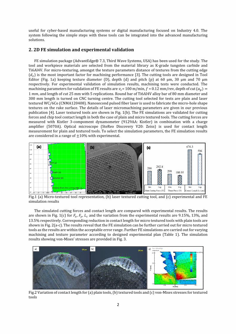
tool and workpiece materials are selected from the material library as K-grade tungsten carbide and Ti6Al4V. For micro-texturing, amongst the texture parameters distance of textures from the cutting edge (𝑑𝑒) is the most important factor for machining performance [3]. The cutting tools are designed in Tool Editor (Fig. 1a) keeping texture diameter (D), depth (d) and pitch (p) at 60 µm, 30 µm and 70 µm respectively. For experimental validation of simulation results, machining tests were conducted. The machining parameters for validation of FE results are 𝑣𝑐= 100 m/min, 𝑓 = 0.12 mm/rev, depth of cut (𝑎𝑝) =
1 𝑚𝑚, and length of cut 25 mm with 5 replications. Round bar of Ti6Al4V alloy bar of 80 mm diameter and 300 mm length is turned on CNC turning centre. The cutting tool selected for tests are plain and laser textured WC/6Co (CNMA120408). Nanosecond pulsed fiber laser is used to fabricate the micro-hole shape textures on the rake surface. The details of laser micromachining parameters are given in our previous publication [4]. Laser textured tools are shown in Fig. 1(b). The FE simulations are validated for cutting forces and chip tool contact length in both the case of plain and micro textured tools. The cutting forces are measured with Kistler 3-compoment dynamometer (9129AA: Kistler) in combination with a charge amplifier (5070A). Optical microscope (SteReo Discovery V20: Zeiss) is used for contact length measurement for plain and textured tools. To select the simulation parameters, the FE simulation results are considered in a range of ±10% with experimental.
Fig.1 (a) Micro-textured tool representation, (b) laser textured cutting tool, and (c) experimental and FE simulation results
The simulated cutting forces and contact length are compared with experimental results. The results are shown in Fig. 1(c) for 𝐹𝑥, 𝐹𝑦, 𝐿𝑐 and the variation from the experimental results are 9.15%, 13%, and
13.5% respectively. Corresponding reduction in contact length for micro textured tools with plain tools are shown in Fig. 2(a-c). The results reveal that the FE simulation can be further carried out for micro textured tools as the results are within the acceptable error range. Further FE simulations are carried out for varying machining and texture parameter according to designed experimental plan (Table 1). The simulation results showing von-Mises’ stresses are provided in Fig. 3.
Fig.2 Variation of contact length for (a) plain tools, (b) textured tools and (c) von-Mises stresses for textured tools

3
Response surface methodology with 3-factor 5-level central composite design (CCD) is selected for
running simulations. RSM combines the mathematical and statistical technique for modeling and analysis of data with the objective to optimize the response[5]. The different values of design variables are selected for cutting speed (𝑣𝑐 , 𝑚/𝑚𝑖𝑛), feed (𝑓, 𝑚𝑚/𝑟𝑒𝑣) and distance of texture from the cutting edge(𝑑𝑒 , µ𝑚). Table 1 shows the variation of the variables at different levels with coded (±𝛼) values and actual (±1) values. The selection of machining parameters are based on the recommended valued for uncoated tungsten carbide cutting tool under dry cutting. The responses of FE simulation observed are main cutting force (𝐹𝑥), thrust force (𝐹𝑦), average cutting temperature (𝑇𝑎𝑣𝑔) and tool chip contact length (𝐿𝑐) and given
in Table 2.
Table 1 The level of parameters for CCD Design
Levels
Parameters −𝛼 −1 0 +1 +𝛼
𝑣𝑐 26.3 40 60 80 93.6
𝑓 0.052 0.08 0.12 0.16 0.187
𝑑𝑒 52.7 80 120 160 187.3
3. Results and discussion
Fig. 4 shows the mean effect plot of the responses for input variables obtained from ANOVA analysis.
Cutting speed and feed are the most influential factors for 𝐹𝑥, 𝐹𝑦, and 𝑇𝑎𝑣𝑔 and the output values increase
with feed. Cutting forces(𝐹𝑥, and 𝐹𝑦) decrease with cutting speed whereas 𝑇𝑎𝑣𝑔 increases.

4
Fig. 3 FE simulation showing von-Mises stresses for the selected design of experiment
Table 2 Design matrix for 3-factor 5-level CCD with responses in terms of cutting forces, contact length
and average tool temperature
Run 𝑣𝑐 (m/min)
𝑓 (mm/rev)
𝑑𝑒 (µm)
𝐹𝑥 (N)
𝐹𝑦
(N)
𝐿𝑐 (µm)
𝑇𝑎𝑣𝑔
(℃) 1 40 0.08 80 215 214 833.3 602 2 80 0.08 80 202 198 731.2 798 3 40 0.16 80 343 267 932.3 662 4 80 0.16 80 324 243 1152.3 852 5 40 0.08 160 197 170 862.4 580 6 80 0.08 160 192 165 248.9 768 7 40 0.16 160 330 234 725.8 680 8 80 0.16 160 314 212 588.7 864 9 26.36 0.12 120 287 235 631.3 488
10 93.63 0.15 120 260 195 401.2 838 11 60 0.052 120 155 131 153.8 431 12 60 0.187 120 347 225 695.3 778 13 60 0.12 52.73 258 194 400.1 708 14 60 0.12 187.27 268 204 719.5 728 15 60 0.12 120 267 210 355.1 679 16 60 0.12 120 267 210 308.8 679 17 60 0.12 120 267 210 370.8 679 18 60 0.12 120 267 210 447.3 679
Fig. 4 Main effect plot for cutting force (𝐹𝑥), thrust force(𝐹𝑦), contact length (𝐿𝑐) and average tool
temperature (𝑇𝑎𝑣𝑔)
The variation in cutting forces and temperature show least values for texture parameter (𝑑𝑒) at 120 µm. At
both low and high 𝑑𝑒 levels, the cutting forces, and temperature are higher due to heavy concentrated stress
at the tool nose (in case of low 𝑑𝑒 values) and unavailability of the textured area for reduced contact length
(in high 𝑑𝑒 values). The variation in contact length for the input variables shows that the minimum contact
length achieved for lowest feed. Concerning the texture parameter (𝑑𝑒), the lower contact length values are
obtained for 52.7 µm and 120 µm values. The initial 𝑑𝑒 value shows the highest reduction in contact length
5
due to a high number of textured spaces reducing contact with flowing chips. However, with textures close
to the cutting edge (𝑑𝑒= 52.7 µm), there remains a chance of tool fracture at machining at high speed and
feed combination. Considering the fact, 𝑑𝑒=120 µm can be preferred for fabrication of textures over tool
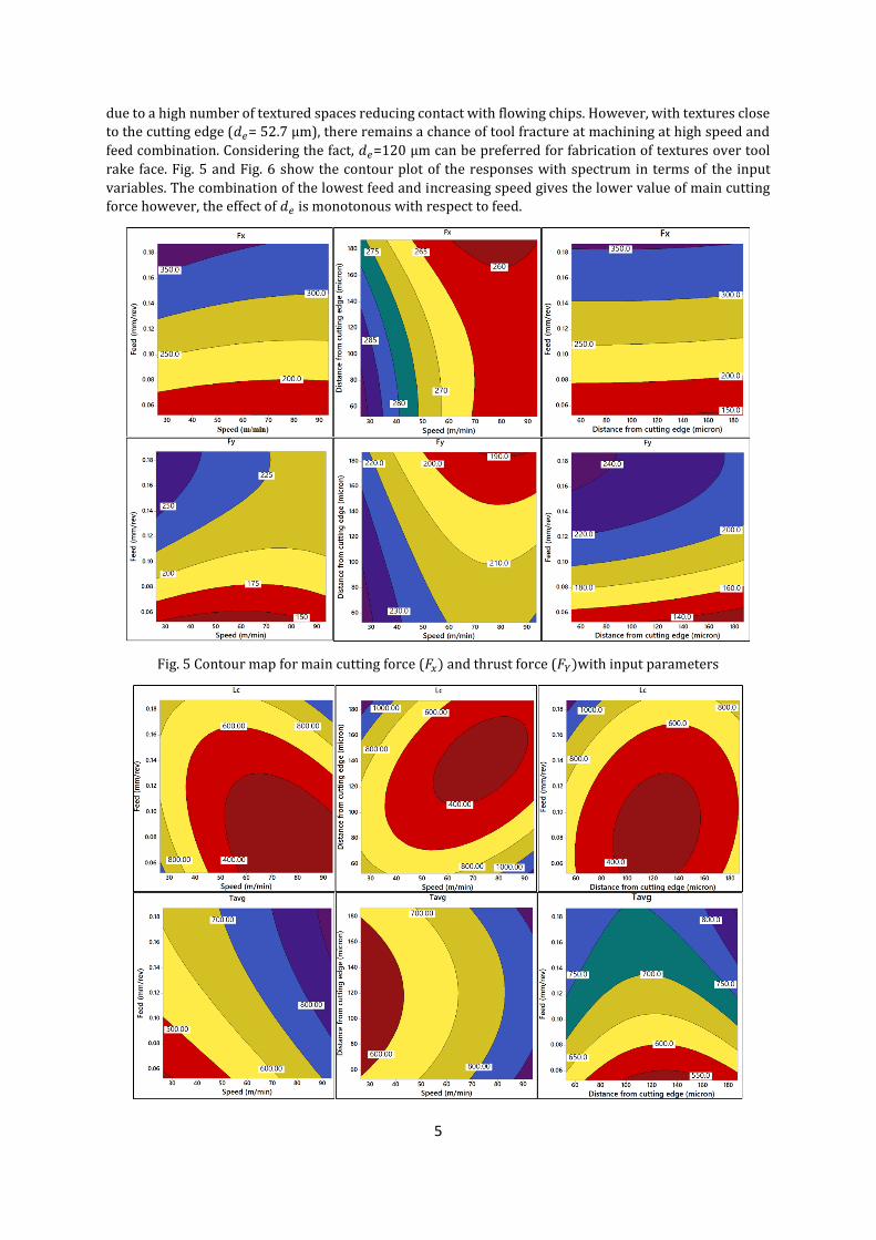
rake face. Fig. 5 and Fig. 6 show the contour plot of the responses with spectrum in terms of the input
variables. The combination of the lowest feed and increasing speed gives the lower value of main cutting
force however, the effect of 𝑑𝑒 is monotonous with respect to feed.
Fig. 5 Contour map for main cutting force (𝐹𝑥) and thrust force (𝐹𝑌)with input parameters
6
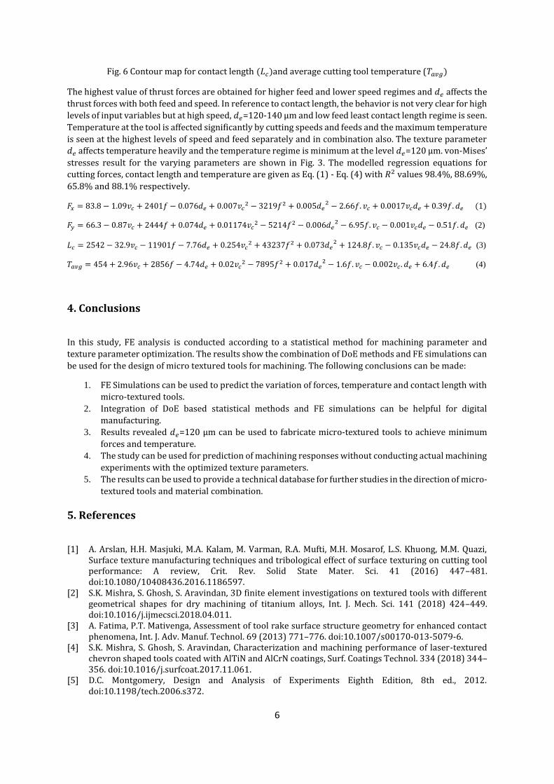
Fig. 6 Contour map for contact length (𝐿𝑐)and average cutting tool temperature (𝑇𝑎𝑣𝑔)
The highest value of thrust forces are obtained for higher feed and lower speed regimes and 𝑑𝑒 affects the
thrust forces with both feed and speed. In reference to contact length, the behavior is not very clear for high
levels of input variables but at high speed, 𝑑𝑒=120-140 µm and low feed least contact length regime is seen.
Temperature at the tool is affected significantly by cutting speeds and feeds and the maximum temperature
is seen at the highest levels of speed and feed separately and in combination also. The texture parameter
𝑑𝑒 affects temperature heavily and the temperature regime is minimum at the level 𝑑𝑒=120 µm. von-Mises’
stresses result for the varying parameters are shown in Fig. 3. The modelled regression equations for
cutting forces, contact length and temperature are given as Eq. (1) - Eq. (4) with 𝑅2 values 98.4%, 88.69%,
65.8% and 88.1% respectively.
𝐹𝑥 = 83.8 − 1.09𝑣𝑐 + 2401𝑓 − 0.076𝑑𝑒 + 0.007𝑣𝑐2 − 3219𝑓2 + 0.005𝑑𝑒
2 − 2.66𝑓. 𝑣𝑐 + 0.0017𝑣𝑐𝑑𝑒 + 0.39𝑓. 𝑑𝑒 (1)
𝐹𝑦 = 66.3 − 0.87𝑣𝑐 + 2444𝑓 + 0.074𝑑𝑒 + 0.01174𝑣𝑐2 − 5214𝑓2 − 0.006𝑑𝑒
2 − 6.95𝑓. 𝑣𝑐 − 0.001𝑣𝑐𝑑𝑒 − 0.51𝑓. 𝑑𝑒 (2)
𝐿𝑐 = 2542 − 32.9𝑣𝑐 − 11901𝑓 − 7.76𝑑𝑒 + 0.254𝑣𝑐2 + 43237𝑓2 + 0.073𝑑𝑒
2 + 124.8𝑓. 𝑣𝑐 − 0.135𝑣𝑐𝑑𝑒 − 24.8𝑓. 𝑑𝑒 (3)
𝑇𝑎𝑣𝑔 = 454 + 2.96𝑣𝑐 + 2856𝑓 − 4.74𝑑𝑒 + 0.02𝑣𝑐2 − 7895𝑓2 + 0.017𝑑𝑒
2 − 1.6𝑓. 𝑣𝑐 − 0.002𝑣𝑐 . 𝑑𝑒 + 6.4𝑓. 𝑑𝑒 (4)
4. Conclusions
In this study, FE analysis is conducted according to a statistical method for machining parameter and
texture parameter optimization. The results show the combination of DoE methods and FE simulations can
be used for the design of micro textured tools for machining. The following conclusions can be made:
1. FE Simulations can be used to predict the variation of forces, temperature and contact length with
micro-textured tools.
2. Integration of DoE based statistical methods and FE simulations can be helpful for digital
manufacturing.
3. Results revealed 𝑑𝑒=120 µm can be used to fabricate micro-textured tools to achieve minimum
forces and temperature.
4. The study can be used for prediction of machining responses without conducting actual machining
experiments with the optimized texture parameters.
5. The results can be used to provide a technical database for further studies in the direction of micro-
textured tools and material combination.
5. References
[1] A. Arslan, H.H. Masjuki, M.A. Kalam, M. Varman, R.A. Mufti, M.H. Mosarof, L.S. Khuong, M.M. Quazi, Surface texture manufacturing techniques and tribological effect of surface texturing on cutting tool performance: A review, Crit. Rev. Solid State Mater. Sci. 41 (2016) 447–481. doi:10.1080/10408436.2016.1186597.
[2] S.K. Mishra, S. Ghosh, S. Aravindan, 3D finite element investigations on textured tools with different geometrical shapes for dry machining of titanium alloys, Int. J. Mech. Sci. 141 (2018) 424–449. doi:10.1016/j.ijmecsci.2018.04.011.
[3] A. Fatima, P.T. Mativenga, Assessment of tool rake surface structure geometry for enhanced contact phenomena, Int. J. Adv. Manuf. Technol. 69 (2013) 771–776. doi:10.1007/s00170-013-5079-6.
[4] S.K. Mishra, S. Ghosh, S. Aravindan, Characterization and machining performance of laser-textured chevron shaped tools coated with AlTiN and AlCrN coatings, Surf. Coatings Technol. 334 (2018) 344–356. doi:10.1016/j.surfcoat.2017.11.061.
[5] D.C. Montgomery, Design and Analysis of Experiments Eighth Edition, 8th ed., 2012. doi:10.1198/tech.2006.s372.