Embed Size (px)
Citation preview

Optimization of LSOfor Time-of-Flight PETOptimization of LSO
for Time-of-Flight PET
W. W. Moses1, M. Janecek1, M. A. Spurrier2, P. Szupryczynski2,3 ,W.-S. Choong1, C. L. Melcher2, and M. Andreaco3
1Lawrence Berkeley National Laboratory2University of Tennessee, Knoxville
3Siemens Medical Solutions
October 21, 2008
• Motivation• Reflector Optimization• LSO Optimization• PMT Optimization
Outline:
This work was supported by the NIH (NIBIB grant No. R01-EB006085).

Time-of-Flight in PETTime-of-Flight in PET
• Can localize source along line of flight.
• Time of flight information reduces noise in images.
• Variance reduction given by 2D/ct.
• 500 ps timing resolution 5x reduction in variance!
c = 30 cm/ns500 ps timing resolution
7.5 cm localization
•Time of Flight Provides a Huge Performance Increase!•Largest Improvement in Large Patients
•Time of Flight Provides a Huge Performance Increase!•Largest Improvement in Large Patients
D

Commercial TOF PET w/ LSOCommercial TOF PET w/ LSO
~550 ps Coincidence Timing Achieved~550 ps Coincidence Timing Achieved

Our Goal:“Demonstration” TOF PET Camera
Our Goal:“Demonstration” TOF PET Camera
Achieve the Best Timing Possible w/ LSOAchieve the Best Timing Possible w/ LSO
• With better timing resolution (t), huge gains predicted(23x variance reduction for 100 ps timing)
• Measure image improvement vs. timing resolution
• Use LSO scintillator
– Don’t change other factors that influence SNR(efficiency, scatter fraction, etc.)

What Limits Timing Resolution?What Limits Timing Resolution?
CrystalGeometry
326 psPMT
PMT
PMT 422 ps
Light Sharing 454 ps
PMT Array 274 ps
Baseline 160 ps
Non-TOF Block Detector Module
•Many Factors•“Optical Geometry” Particularly Important
•Many Factors•“Optical Geometry” Particularly Important

Timing Values will be for a Single Detector*Timing Values will be for a Single Detector*1 cm3
BaF2H5321 R9800
ShapingAmplifier
CFDCanberra 454
F=0.2, D=0.6 ns
TACOrtec 566
Start Stop
ADCNI-7833R
Ge-68LSO
+/- fwhm
Photopeak events
• Only Accept Events in Photopeak Window• Subtract (in Quadrature) 150 ps Trigger Contribution
• Only Accept Events in Photopeak Window• Subtract (in Quadrature) 150 ps Trigger Contribution
*Unless explicitly mentioned otherwise
CFDCanberra 454
F=0.2, D=0.6 ns
Pulse Height
Timing
Photopeakevents
Windowed Timing
TriggerDetector
TestDetector
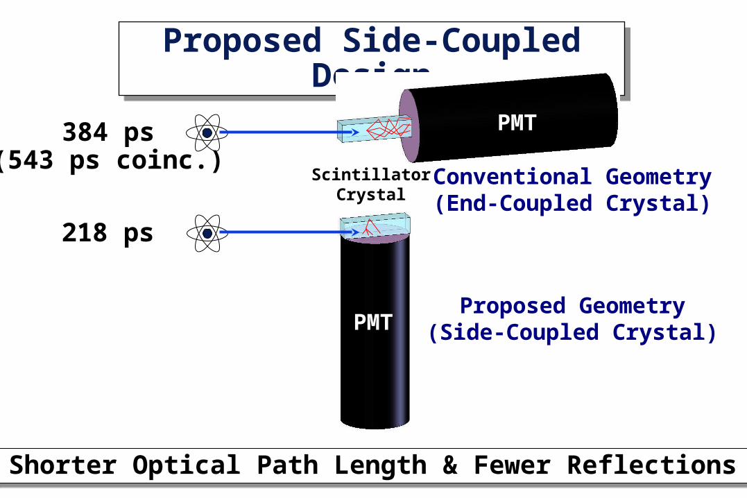
Proposed Side-Coupled DesignProposed Side-Coupled Design
Proposed Geometry(Side-Coupled Crystal)
ScintillatorCrystal
PMT
PMT
Shorter Optical Path Length & Fewer ReflectionsShorter Optical Path Length & Fewer Reflections
Conventional Geometry(End-Coupled Crystal)
384 ps(543 ps coinc.)
218 ps

Detector Module DesignDetector Module Design
PMT
(HamamatsuR-9800)
Two LSO Crystals(each 6.15 x 6.15 x 25 mm3)
Reflector
(on all five faces of each crystal, including the face between the
two crystals)
Optical Glue
(between lower crystal faces and PMT)
Hole in ReflectorOn Top Face of
Crystals
Two Side-Coupled Scintillator Crystals per PMTTwo Side-Coupled Scintillator Crystals per PMT

Detector Ring GeometryDetector Ring Geometry
Crystals Decoded by Opposing PMTCrystals Decoded by Opposing PMT
Exploded View
• Top face of each crystal (with hole in reflector) is coupled via a small (<1 mm) air gap to the edge of one opposing PMT.
• Light seen by the opposing PMT is used to decode the crystal of interaction.
Crystal ofInteraction

Camera GeometryCamera GeometrySection of Detector Ring
• Detector ring is 825 mm diameter, 6.15 mm axial• 192 detector modules, 384 LSO scintillator crystals• Adjustable gap (6 – 150 mm) between lead shields allows
“scatter-free” and “3-D” shielding geometries
Lead Shielding
Modules
“Real” Single-Ring PET Camera for Humans & Phantoms“Real” Single-Ring PET Camera for Humans & Phantoms

Optimization: Surface Finish & ReflectorOptimization: Surface Finish & Reflector
Both Performance & Manufacturing ImportantBoth Performance & Manufacturing Important
• Best Possible Timing Resolution
• Good Light Collection Efficiency
• Good Energy Resolution
• Manufacturable:
• Easy
• Reliable & Reproducible
• Rugged
• Well-Controlled Light from Top Surface
• Starting Point: Saw Cut LSO w/ Teflon Tape
Requirements

Surface & Reflector Optimization MethodSurface & Reflector Optimization Method
Measure Percentage Change in TimingMeasure Percentage Change in Timing
• Measure Timing of “Raw” Crystal(saw cut finish, Teflon tape reflector)
• Apply Surface Treatment
• Apply Reflector
• Re-Measure Timing
• Compute Percent Change
• Repeat for 5 Crystals & Average Results
• Do for All Surface / Reflector Combinations(>100 crystals, each measured twice)
R-9800
• 6.15 x 6.15 x 25 mm3
• Reflector on 5 Sides• Optical Grease• No Hole on Top
Same PMT forall measurements

Surface & Reflector ResultsSurface & Reflector Results
Reflector Saw Cut Chemically MechanicallyEtched Polished
Air GapTeflon 1.00 ± 0.17 0.94 ± 0.10 1.06 ± 0.09ESR 1.01 ± 0.08 0.96 ± 0.16 1.08 ± 0.08Lumirror 1.03 ± 0.13 0.96 ± 0.06 1.04 ± 0.12
GluedESR 0.99 ± 0.09 0.98 ± 0.03 1.01 ± 0.18Lumirror 1.04 ± 0.10 0.97 ± 0.10 0.98 ± 0.22Melinex 1.01 ± 0.16 0.99 ± 0.06 1.01 ± 0.20Epoxy 1.00 ± 0.16 0.95 ± 0.09 1.00 ± 0.15
Paint 0.96 ± 0.03
Average
1.001.021.01
0.991.001.000.98
Average 1.01 0.96 1.03

Finished CrystalFinished Crystal
Etched Surface, White Primer Spray PaintEtched Surface, White Primer Spray Paint
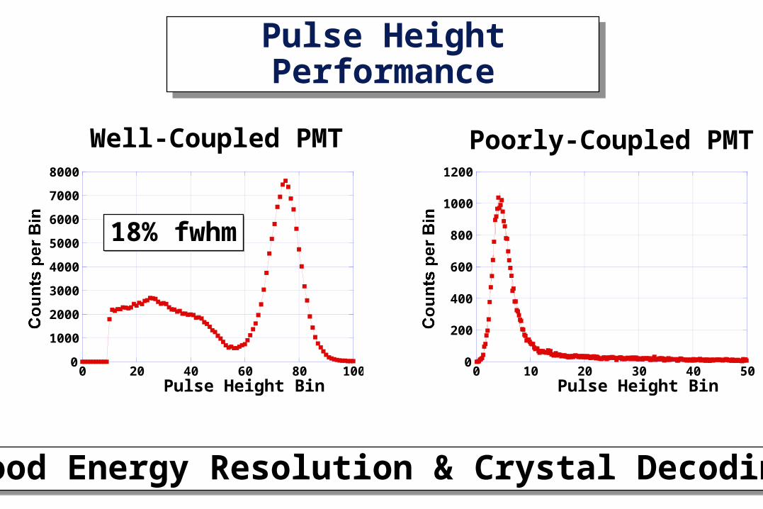
Pulse Height PerformancePulse Height Performance
Good Energy Resolution & Crystal DecodingGood Energy Resolution & Crystal Decoding
0
1000
2000
3000
4000
5000
6000
7000
8000
0 20 40 60 80 100
Counts per Bin
Pulse Height Bin
Well-Coupled PMT Poorly-Coupled PMT
18% fwhm18% fwhm
0
200
400
600
800
1000
1200
0 10 20 30 40 50
Counts per Bin
Pulse Height Bin

Optimization: LSO CompositionOptimization: LSO Composition
• Predicted Timing Resolution 1/sqrt(I0)• Want High Total Light Output & Short Decay Time
• Possible By Co-Doping LSO With Calcium
• Predicted Timing Resolution 1/sqrt(I0)• Want High Total Light Output & Short Decay Time
• Possible By Co-Doping LSO With Calcium
0
20
40
60
80
100
120
0 50 100 150 200
25 ns decay time50 ns decay time
Intensity
Time (ns)
• Both Scintillators Have Same Light Output (photons/MeV)• Red Decay Time is 2x Longer Than Blue Decay Time
I(t) = I0 exp(-t/)
Light Output = I0
I0

25
30
35
40
45
50
0.95 1 1.05 1.1 1.15 1.2 1.25 1.3
Decay Time (ns)
Relative Light Output
Optimization: LSO CompositionOptimization: LSO Composition
Ca-Doping Gives High Light Output & Short Ca-Doping Gives High Light Output & Short
Normal LSO High Light Out
Short The Good Stuff!
= Ca-doped
0.1%0.2%0.4%
0.3%

LSO Composition Optimization MethodLSO Composition Optimization Method
Measure Time Resolution vs. Initial IntensityMeasure Time Resolution vs. Initial Intensity
• Get Samples of Normal & Co-Doped LSO
• Measure Decay Time
• Measure Relative Light Output
• Compute Initial Intensity I0
• Measure Timing Resolution
• Plot Timing Resolution vs. I0
R-9800
• 5 x 5 x 5 mm3
• Saw Cut Surface• Teflon on 5 Sides• Optical Grease
Same PMT forall measurements

• Ca-Doping Gives Good Timing Resolution• ~15% Improvement Over Normal LSO
• Ca-Doping Gives Good Timing Resolution• ~15% Improvement Over Normal LSO
150
160
170
180
190
200
210
220
230
80 100 120 140 160 180 200Time Resolution (ps fwhm)Initial Intensity (I
0)
Normal LSO
Scaled by1/sqrt(I0)
Measured Results: LSO CompositionMeasured Results: LSO Composition
= Ca-doped
0.1%
0.2%
0.4%0.3%

Optimization: Photomultiplier TubeOptimization: Photomultiplier Tube
• Predicted Timing Resolution 1/sqrt(QE)• Want High Quantum Efficiency Version of PMT
• Predicted Timing Resolution 1/sqrt(QE)• Want High Quantum Efficiency Version of PMT
Peak QE
Blue Sensitivity Index

PMT Optimization MethodPMT Optimization Method
Measure Time Resolution vs. Blue SensitivityMeasure Time Resolution vs. Blue Sensitivity
• Couple “Standard” LSO Crystal to PMT(“normal” LSO, etched surface finish,Lumirror reflector glued to five sides)
• Measure Timing
• Repeat for all PMTs
• Measure twice for each PMTR-9800
• 6.15 x 6.15 x 25 mm3
• Chemically etched• Lumirror reflector• Optical Grease• Same Crystal for
all measurements

190
200
210
220
230
240
250
10 11 12 13 14 15Time Resolution (ps fwhm)Blue Sensitivity Index
• Increased QE Improves Timing Resolution by 7%• Expect 10% Improvement with 35% SBA PMT
• Increased QE Improves Timing Resolution by 7%• Expect 10% Improvement with 35% SBA PMT
Normal (“28% QE”) PMTs
Measured Results: High QE PMTsMeasured Results: High QE PMTs
Scaled by1/sqrt(Blue Index)
= “32% QE” PMTs

• Intrinsic Timing Resolution is 63 ps fwhm• With Detectors, Same Timing as NIM Electronics
• Intrinsic Timing Resolution is 63 ps fwhm• With Detectors, Same Timing as NIM Electronics
Shaper
Shaper
4 ADCs
4 ADCsCFD
Sum
Sum
CFD
CERNTDC
FPGA
Out…
Based on Siemens “Cardinal” electronics.
CFD triggers if any of 4 adjacent modules fire.
CERN HPTDC digitizes arrival time w/ 24 ps LSB.
Pulse height from all 8 modules read out on every trigger.
FPGA uses pulse heights to identify interaction crystal.
FPGA also does calibration, event formatting, etc.
ElectronicsElectronics

SummarySummary
• TOF PET with Significantly Better Timing is Possible• To Achieve, We Must “Think Outside the Block Detector”
• TOF PET with Significantly Better Timing is Possible• To Achieve, We Must “Think Outside the Block Detector”
Hardware Single Coinc. TOF (ps fwhm) (ps fwhm) GainEnd-Coupled Crystal 384 544 4.3
Side-Coupled Crystal 218 309 7.6
Etched, Reflector Paint 227 321 7.3
Co-Doped LSO 182 258 9.1
32% QE PMT 155 219 10.6
35% QE “SBA” PMT 148 209 11.1

Future TOF PET Design?Future TOF PET Design?
•Depth of Interaction & 150 ps Timing Resolution•11x Reduction in Variance in Practical Geometry•Depth of Interaction & 150 ps Timing Resolution•11x Reduction in Variance in Practical Geometry
ScintillatorArray
ThinnedSiPM Array


![^^?^^?^mW?^;. Amended and restated...mMm^wm^w^^^ ^mtt^?^]^BM^ ^ ^±m^±m^w^w?^wmM^±(.w^ »^r;W o 11.3 ^WX^^W1?^^^^^.WWWW^^ ^-^m?^ww^ii^w±ii^m?^w^ ^m^Wr. N^NN^ ^^mMTWWW^te^ m^^wt^,](https://img.pdfslide.net/doc/110x75/60bbb6ab20632a6a74324b96/mw-amended-and-restated-mmmwmw-mttbm-mmwwwmmw.jpg)