Embed Size (px)
Citation preview
ARTICLE IN PRESS
0165-1684/$ - se
doi:10.1016/j.sig
�Correspondfax: 34 93 401 72
E-mail addre
Signal Processing 86 (2006) 1755–1772
www.elsevier.com/locate/sigpro
Optimization of wireless communication systemsusing cross-layer information
Luis Alonso, Ramon Agustı�
Department of Signal Theory and Communications, Polytechnic University of Catalonia (UPC), Jordi Girona 1-3,
Campus Nord, Edifici D4, 08034 Barcelona, Spain
Received 3 January 2005; received in revised form 15 September 2005; accepted 15 September 2005
Available online 21 December 2005
Abstract
In the last few years, a new design paradigm has arisen in the field of wireless communications research: the so-called
cross-layer optimization. In fact, this paradigm implies the redefinition of the overall design strategies for this kind of
systems as it breaks the classical OSI model. The endless need for higher and higher bit rates, stringent QoS requirements
and anytime-anywhere connections for wireless systems leads to the necessity of squeezing to the utmost the available radio
bandwidth. Cross-layer plays a key role to achieve this goal. The amount of literature about this issue is still relatively
scarce, but the premier published results show that the potential obtainable gains are worthy to deserve the increasingly
attention that cross-layer is getting. This paper revises the different definitions used for such paradigm, describes the
possible mechanisms that can be fitted into the definitions, outlines research challenges to meet in the near future, and
analyses different strategies proposed by the authors showing some recent novel results for CDMA-based and WLAN
systems.
r 2005 Elsevier B.V. All rights reserved.
Keywords: Wireless communications; Cross-layer; MAC protocols; CDMA; WLAN
1. Introduction
The OSI model is a widely known well-acceptedframework for communication systems [1,2]. Thismodel is based on the Shannon separation principlewhich is known to be appropriate for manypractical applications. With this model, systemsare decomposed in seven layers (physical–link–net-work–transport–session–presentation–application).Each one of them is responsible of a sub-set of the
e front matter r 2005 Elsevier B.V. All rights reserved
pro.2005.09.029
ing author. Tel.: 34 93 401 71 95;
00.
sses: [email protected] (L. Alonso),
.edu (R. Agustı).
operational functions of the system. Messages areinterchanged between entities of the same layer inboth transmitter and receiver. Each layer is aware ofits own layer messages, it embeds its informationinto upper layer messages when messages go downin the layer stack and it discards the lower layersinformation when messages go up.
This model has proved to be quite useful fordeveloping smart algorithms and techniques fordifferent communication systems, achieving properworking mechanisms. Considerable research effortshave been put into improving the efficiency ofindividual layers. At the physical layer (PHY),advanced signal processing techniques have beendevised to face problems such as noise, interference
.
ARTICLE IN PRESS
PHYSICAL LAYER PHYSICAL LAYER
Node i as transmitter Node j as receiver
Agent Manager
Physical State(Parameter Vector)
MAC/RLC
ROUTING/RRM
Primitives
Primitives
MAC/RLC
ROUTING/RRM
Fig. 2. Example of cross-layer interaction through an Agent
Manager.
L. Alonso, R. Agustı / Signal Processing 86 (2006) 1755–17721756
and unwanted signal replicas caused by the randomand time-varying nature of radio channels [3–5].
Besides, a great variety of medium access control(MAC) schemes have been developed for wire-less systems. In particular, two innovative aspectshave been taken into account when designingMAC protocols for 4G systems: the packet swit-ched nature of multimedia communications andthe need to fulfil service-dependent QoS require-ments [6–13].
At link layer, several ARQ and FEC mechanismshave been developed and studied in order to operatein wireless communication systems [14–19].
The inherent mobility of the communicationnodes in wireless systems must be carefully con-sidered in the design of network and transportlayers. Indeed, these layers are key pillars of wirelessnetworks as they must guarantee anywhere seamlessend-to-end connections. For example, TCP is awidely used transport protocol whose impact in awireless environment has been recently studied [22].Routing protocols are one of the widest studiedareas for wireless communication systems [20,21].
However, advances attained in the different layershave barely taken into account those achieved inother layers. Actually, since a few years ago, eachlayer research has widely ignored the other layers. Itseems clear that system performance improvementscould arise from some communications betweendifferent layers, having in mind in the system designcertain smart interaction between them. This fore-sight has led to a new paradigm: cross-layeroptimization.
APPLICATI
PRESENTAT
SESSION
TRANSPO
NETWOR
LINK
PHYSICA
MAC
Fig. 1. Possible cross-lay
Fig. 1 shows the OSI-layered model and a subsetof the possible cross-layer interactions that can beconsidered when performing a cross-layer design.This graph allows making out the vast field ofresearch to explore in this area.
As an example, Fig. 2 shows with arrows thedifferent control flows needed to provide a cross-layer interaction between physical and upper layersof two remote nodes. When two nodes commu-nicate, the receiving one measures the physical state,also called channel state information (CSI), which isnormally a vector of real values. An entity calledAgent Manager in the Fig. 2, estimates, measuresand selects the appropriate values to be sent to the
ON
ION
RT
K
L
er communications.
ARTICLE IN PRESSL. Alonso, R. Agustı / Signal Processing 86 (2006) 1755–1772 1757
upper layers of the transmitting node. These layerswill actuate accordingly to adapt to the actualchannel conditions, performing the cross-layerinteraction. This Agent is the responsible of settingup and formatting the control information so thatthe cross-layer overload is minimized.
This example outlines a cross-layer interactionbetween two different nodes (namely transmitterand receiver), but it is worth to note that cross-layerdesign could also include the interaction betweendifferent layers of the same node of the commu-nications system.
Finally, note that in each specific communicationssystem, the suitability of the application of ancertain cross-layer interaction should be carefullystudied in order to assess that real system enhance-ments could be achieved.
The paper is organized as follows: Section 2describes the state of the art about cross-layerissues, focusing on the RRM aspects that arecovered by the other sections. Then, Section 3addresses a tutorial description of the cross-layerdesign paradigms, trade-offs, control informationissues, and it also outlines a classification of cross-layer mechanisms. Section 4 is devoted to the studyin depth of the interaction between physical andMAC layers and its obtainable benefits. Specifically,three different representative scenarios are analysedand cross-layer mechanisms for them are introducedand described. Each subsection also shows numer-ical figures of the achieved gains. Finally, Section 5is devoted to assess the conclusions.
2. State of the art
In recent years, research efforts focused on cross-layer design have been progressively increasing,leading to the huge amount of recent literature onthe topic. Then, only some examples of eachsubsection of the research are cited.
Yeh and Cohen proposed a theoretical frame-work for cross-layer design [24] in the context ofradio resource management (RRM) focusing onresource allocation algorithms. More recently, Yehalso developed this framework in [35]. Othertutorial-like very useful descriptions of the generalcross-layer optimization paradigm have been alsopublished [28–30].
Then, cross-layer research has been split intodifferent fields of applications. Obviously, wirelesscommunications are the most interesting researchtarget for cross layering, due to the inherent
variability of the radio channel and the potentialenhancements that other layers can attain fromknowing information about its state. Some researchhas been developed for general unspecific wirelesssystems, focusing specially on MAC issues[31,32,37,40], while others study in depth RRMissues as the optimal bandwidth allocation [43] orthe optimal power assignment for this kind ofsystems [44,45,48]. Regarding specific types ofnetworks or applications, for instance, ad hocwireless networks have been an extensive field ofcross-layer research [25,33,46,49] due to the to-tally wireless nature of the communications system.Also sensor networks, that represent an specifickind of ad hoc networks, have been a target forsome cross-layer optimization developments[36,38,41]. Regarding wireless networks with infra-structure-based support, CDMA-based systems[39,42] and WLAN systems [26,34,47] have beenalso a extensive research target for cross-layerdesign, focusing also in specific applications asmultimedia transmissions [26,42,43]. Some recentresults of the authors about the specific interactionbetween the physical layer and the MAC aredescribed in Section 4.
On the other hand, nowadays some R&D projectsfunded by the European Commission deal with thestudy of cross-layer interactions. Two IST STREPprojects, the 4G MC-CDMA multiple-antennasystem On chip for radio enhancements (4MORE,[57]) and the jointly optimising multimedia trans-mission in IP-based wireless networks (PHOENIX,[58]) address cross-layer issues.
The objective of 4MORE is to research, develop,integrate, and validate a cost effective, low powersystem on chip (SoC) solution for multi-antennaMC-CDMA mobile terminals, based on jointoptimisation of layers 1 and 2 functions, whereasthe aim of PHOENIX is to develop a schemeoffering the possibility to let the application world(source coding, ciphering) and the transmissionworld (channel coding, modulation) to talk to eachother over an IPv6 protocol stack (network world),so that they can jointly develop an end-to-endoptimised wireless communication link.
There is also a project within an IST Network ofExcellence, in particular the one named NewCom(network of excellence on wireless communications,[59]) that is focused on cross-layer optimizations.Some of the general concepts and ideas presented inthis paper come from the first discussions within thisproject.

ARTICLE IN PRESSL. Alonso, R. Agustı / Signal Processing 86 (2006) 1755–17721758
3. Cross-layer design
Several issues must be considered when under-taking cross-layer designs, being the additionalsignalling needed to extract relevant parametersfrom one layer that could be useful for other layers[23], a key issue. Then, the trade off betweenoverhead and efficiency improvement should beanalysed. Also, an appropriate logical channel,either common or dedicated, must be identifiedand reserved to transfer information between layerentities. In addition, different cross-layer architec-tures could be envisaged. Regarding the possiblestructures, we can basically divide them into twomain categories:
�
Each layer is modified according to the cross-layerinteraction with the other layers. This means thatsome internal parameters of the protocol stack ateach layer should be modified taking into accountsome information about the state of the otherlayers. For example, the structure of the MACframe can be changed when it is known that a deepfading is present in the channel. � An external entity manages the cross-layer inter-actions and defines the corresponding interfacesand primitives with each layer. We will call itcross-layer Manager. Fig. 3 shows the blockstructure of this kind of architecture.
APPLICATION
PRESENTATION
SESSION
TRANSPORT
NETWORK
LINK
PHYSICAL
MAC
Fig. 3. Cross-layer des
In the next sub-sections, the different aspects ofcross-layer design mentioned above are further
developed in order to achieve a valuable gain inwireless systems.3.1. Trade-off between cross-layer efficiency and
overhead
When targeting cross-layer designs, normally anumber of overheads turn up. For example,exploiting PHY layer will usually require certainoverhead to transport the PHY layer informationfrom entities such as smart antennas processingsystems. Also training sequences may be needed forthe accurate estimation of specific PHY layer state.Additional measurements at different layers may berequired as well in order to extract locationinformation to be exploited by a physical layer-aware routing algorithm. Besides, various methodsfor extraction, embedding and conveying reliabilityinformation (such as time-varying nature, predict-ability, confidence level, estimation accuracy, etc)along with the transmitted parameter set should bepresent and so on. Indeed, cross-layer informationneeds to be exchanged between entities in remotenodes by means of specific-purpose signallingchannels.
In all the above cases, performance versusassociated signalling trade-offs must be carefully
CROSS-LAYER MANAGER
ign architecture.

ARTICLE IN PRESSL. Alonso, R. Agustı / Signal Processing 86 (2006) 1755–1772 1759
analysed and assessed. As a result, the issues ofinformation reliability and its partial knowledge atthe end will arise as a consequence of noisyestimation procedures, quantization stages prior tomapping CSI into a feedback signalling channel,hardware limitations or, alternatively, as a result oftransmission errors in the signalling channels, etc. Insummary, the following issues should be addressedwhen tackling the trade-off in cross-layer optimiza-tion between control information and efficiencyimprovement:
�
Number of entities and of layers involved incross-layer information exchanges. � Definition of the CSI proper information valuesuseful for cross-layer adaptation.
� The associated increase in signalling load bothfor parameter extraction and transmission.
� The degree of robustness to channel errors. � Timing and delay constraints, regarding theprocessing capacities of the involved entities.
� The resulting benefits in terms of system perfor-mance.
Taking into account this trade-off, we coulddistinguish four categories of cross-layer designthat appear to be at the forefront of current re-search [55].
(1)
The first category appears when considering theeffects of one protocol layer on another.Certainly, better efficiencies can be attainedmaking the interaction between relevant para-meters of different layer protocols consistent.Then, this cross-layer interaction does not implyany communication between protocol layers atall. As an example of this category, we mentionthat it would be a waste of resources if the time-out period of a data-link layer is set to a highervalue than that of any reliable layer above.(2)
The second category consists in an active effortby one protocol layer to deduce the state ofother protocol layers by effectively looking‘‘inside’’ packet headers or by making intelligentdeductions from the traffic pattern of cross-layerdesign, unlike the layered approach currentlyapplied. Then, this strategy does not involvetransmission of additional information betweenlayers. A representative case of this category [35]could be the prioritisation of transport-layeracknowledgment packets by the data-link layer,which has been shown to increase the perfor-mance of wireless schemes by reducing thenumber of time-outs at the transport layer.Also, this strategy reduces the number of re-transmissions, thus saving both wireless spec-trum and energy. However, issues as the use ofsecure protocols which imply that headers fromother layers are encrypted can constrain some ofthe advantages of this approach.
(3)
The third category involves additional informa-tion that is being passed from one layer toanother and bypasses protocol interfaces. Ac-tual protocol structures are not modified. Thatis, the goal of this kind of cross-layer is toinclude the corresponding enhancement withoutmodifying the structure neither the primitives ofall the protocols in the protocol stack. Onlyextra information and processing is added intothe normal primitive packets in order to react ineach layer according to the variations in theother layers. An example of this approach couldbe a router that delivers packets out of the mostappropriate wireless interface according to thestate of the corresponding PHY layer (i.e.GPRS, UMTS, WLAN, etc.) [46].(4)
The fourth area of research is destined towardsmore long-term goals. It aims at modifying theprotocols and their interfaces so that the mostuseful information is passed down and upbetween the layers, either as additional controlsignals, or encoded within the packet headers.As an example of this category, the MACproposal described below in Section 4.2 has anembedded cross-layer interaction. This categoryincludes the cross-layer classical concept as ithas been generally understood up to date in theliterature [22–27,29,30].It is worth mentioning that unlike the fourthcategory described above, in the first category thereis no additional overhead to the use of cross-layertechniques, whilst in the second and third categoriesno overhead is associated but an additional proces-sing power could be required.
3.2. Definition of the control information for cross-
layering
Having in mind the trade off mentioned inSection 3.1, the identification and selection ofrelevant cross-layer parameters to be exchangedamong layers will depend on the functionalitiesbeing considered for cross-layer interaction and
ARTICLE IN PRESSL. Alonso, R. Agustı / Signal Processing 86 (2006) 1755–17721760
possibly on specific air interfaces and systemconcepts. However, a generic four-fold classificationcan be established for cross-layer information:
1.
Channel state information (CSI) including estimatesfor channel impulse response, both in time andfrequency domains, location information, vehicle/mobile speed, signal strength, interference level,interference modelling, condition number, etc.2.
QoS-related parameters, including delay,throughput, bit error rate (BER), packet errorrate (PER) measurements, etc; for each one ofthe layers involved in the cross-layer interaction.3.
Resources made available in the correspondingnode, such as multi-user reception capabilities,number and type of antennas, battery depletionlevel, etc.4.
Traffic pattern offered by each layer to theothers. This includes data traffic information,knowledge of the data rate (constant or variable),data burstiness, data fragmentation, packet sizes,information about queue sizes, etc. In a multi-user environment, it could be needed to exchangethis kind of information among different com-munications nodes.Along with that, special care should be takenwhen assessing the algorithmic complexity in termsof realistic computational capabilities of existinghardware or its anticipated evolution. Computa-tional capability can be vastly different for differenttypes of user terminals (laptop, PDA, cell-phone,etc). Thus, some functionality above physical layershould be able to select the most appropriatescheme out the available ones.
3.3. Classification of cross-layer interactions
As mentioned in Section 1, there is a wide rangeof possible cross-layer interactions. Depending onthe design aspect we focus on, it is possible to dividethe cross-layer techniques into the following cate-gories:
Regarding the entities performing cross layering:
�
Cross-layer inside a single node: The differentlayers of the protocol stack inside a single nodecommunicate and/or adapt to each other depend-ing on the measures they perform or theinformation they exchange. � Cross-layer between remote nodes: As pointed inFig. 3, communicating nodes can exchange cross-
layer information through a control channel sothey can adapt their layers using measures orestimations done in the remote node.
Regarding the number of layers performing crosslayering:
�
Two-layer interaction: The simplest cross-layerapproach involves only two layers that commu-nicate with each other in order to optimise thetransmission efficiency. � Multi-layer interaction: Although no results havebeen published up to date regarding this possibi-lity, the simultaneous interaction between morethan two layers (for example, PHY, MAC androuting) can be investigated. Each layer canadapt taking into account the informationreceived from all the other layers.
In principle, the cross-layer interaction can beenvisaged concerning any of the layers of the OSImodel, and the all the possibilities present potentialbenefits. However, regarding the type of layersperforming cross layering, these interactions shouldbe classified into two main categories:
�
Any layer interacting with PHY layer: As PHYlayer is the most time variant entity in a wirelesscommunications system, any layer can adapt tothe state of the channel. Physical state informa-tion can be sent to any layer (MAC, RLC,routing, application, etc.) in order to improve thesystem efficiency. � Upper layers’ interaction: When the PHY layer isnot involved into the cross-layer interaction, aquite different scenario arises. This is due to thefact that the variability of the layers shouldprobably appear as a consequence of an indirectinfluence with other system parameters or situa-tions such as, among others, congestion, hard-ware failures, application variable QoS andso on.
Among all these possibilities, we are to describe inthe rest of this paper three different MAC-PHYcross-layer interactions, including both remotenodes and a unique node, of the communicationssystem, where the layers interchange explicit controlinformation by means of specific control channels.For this purpose, representative scenarios andcurrent standards for wireless personal communica-tions systems are invoked. In order to get an insight

ARTICLE IN PRESSL. Alonso, R. Agustı / Signal Processing 86 (2006) 1755–1772 1761
of the obtainable benefits of this type of cross-layerinteraction, some recent results will be shown tovalidate the benefits of exploiting cross-layer inwireless communications systems.
It is worth to mention that the final goal of cross-layer design is to improve the performance of end-to-end communications. Therefore, the properconsideration of applications and the source codingof the information to be transmitted should be alsoaddressed in order to be suitable for systems whichinclude cross-layer issues. Due to space constraints,this paper does not go inside this topic and focuseson the interaction between the lowest layers of theOSI model.
4. PHY–MAC cross-layer
As mentioned above, one of the most relevantareas in cross-layer optimisation is the interactionbetween PHY and MAC layers in wireless net-works, as probably it is the most natural integrationdue to the proximity of the layers in the stack andthe inherent variability of the channel state [24–49].The independence of the channel state for differentusers in a multi-user environment arises thepossibility of getting some overall improvementwith the simple idea of selecting ‘always the bestpossible transmission’. Obviously, the fairness in thefinal resource allocation should be considered formost applications in order to maintain a high pernode performance.
Three kinds of results are presented in thissection. Firstly, results for CDMA-based mobilecommunications systems, adopted in the currentstandard for 3G system like UMTS andCDMA2000 are described. Then, other results areshown for generic CDMA systems using a distrib-uted MAC specially suited for cross-layer. Thisspecific MAC protocol is presented and its advan-tages are highlighted. Finally, some results forWLAN systems are also shown, which are relevantas WLANs are currently the most representativewireless systems for medium range and low mobilityscenarios.
4.1. CDMA downlink PHY– MAC interaction
In wideband CDMA systems such as UMTS(Universal Mobile Telecommunications System),advanced radio resource management (RRM)strategies are expected to play an outstanding rolein the optimisation of air interface usage. In order to
meet the QoS requirements of every user, schedulingalgorithms within the UMTS RRM framework areable to assign radio resources in terms of transmis-sion power (Pi) and data rate (rb,i) on a frame-by-frame basis (10ms, or multiples of this for UMTS)for every user i. In CDMA systems, assigning rb,i
determines the required transmission power Pi sinceboth magnitudes are coupled by means of thefollowing expression [56]:
ðPi=Lp;iÞðW=rb;iÞ
I þ PNX
Eb
N0
� �i
. (1)
The left side of this inequality is the bit energyover power noise spectral density ratio (equivalentto the signal-to-noise ratio (SNR)) at the output ofthe CDMA receiver of user i. The numerator of thisratio is computed using Lp,i which is the propaga-tion loss between mobile i and its serving basestation (the ratio Pi over Lp,i represents the receivedpower). The denominator is the total noise plusinterference power, where I accounts for both theintracell and intercell interference and PN is thenoise power. Finally (Eb/No)i is the bit energy overnoise ratio that meets the required block error ratio(BLER) target for user i. Then, the actual bit energyover noise ratio must be always higher or equal tothe target value.
Most of the scheduling policies proposed forCDMA-based systems rely exclusively on trafficconsiderations (traffic class, guaranteed rate, buffersize, etc.) to decide whether a user receives service ornot and which transmission rate is allowed. Then,once a given rb,i is decided for user i, thetransmission power Pi to be assigned can be derivedfrom Eq. (1), taking into account averaged estima-tions of the propagation losses and interferencelevels. In this way, long-term variations in the radiochannel are captured by the radio resource assign-ment in the computation of the allocated meantransmission power Pi. Furthermore, a fast powercontrol mechanism is used in UMTS to follow theshort-term variations of the radio channel and toupdate the transmission power accordingly. Usuallyscheduling policies provide fairness guarantees thatare based mainly on traffic considerations and areirrespective of the conditions of the individual radiochannel perceived for each user. Indeed, thesechannel conditions should also be considered inthe scheduling process and it seems intuitive thatsuch smart scheduling would lead to an efficiencyimprovement.
ARTICLE IN PRESSL. Alonso, R. Agustı / Signal Processing 86 (2006) 1755–17721762
A cross-layer mechanism could be introducedusing short-term information obtained from the fastpower control mechanism to improve the schedulingstrategy in a downlink channel. It is clear that theoverall system efficiency could be enhanced if thisinformation is used to prioritise those transmissionswith better radio conditions (or whose conditionsare getting better).
In the downlink of a WCDMA system, each basestation has a certain total available transmissionpower, PT, which has to be shared among thepossible destination active users. Then, let usconsider a UMTS downlink, where the fast powercontrol mechanism keeps the transmission powerPi(t) needed for user i to the minimum value toensure the Eb/No required for each time t. The basestation, using the power control commands comingfrom each user, adjusts this power dynamically.Furthermore, this power will fluctuate rapidlyaround a certain average value which depends onthe slow varying radio channel conditions.
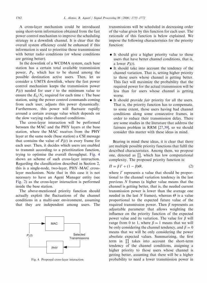
The cross-layer interaction will be performedbetween the MAC and the PHY layers at the basestation, where the MAC receives from the PHYlayer at the same node (base station) a CSI messagethat contains the value of Pi(t) in every frame foreach user. Then, it decides which users are enabledto transmit according to a prioritization function,trying to optimise the overall throughput. Fig. 4shows an scheme of such cross-layer interaction.Regarding the classification described in Section 2,this is a single-node, two-layer, PHY–MAC cross-layer mechanism. Note that in this case it is notnecessary to have an Agent Manager entity (seeFig. 2) as the cross-layer interaction is performedinside the base station.
The above-mentioned priority function shouldactually exploit the fluctuations of the channelconditions in a multi-user environment, assumingthat they are independent among users. The
MAC
PHY
SelectedTransmissions
Pi (t )
Fig. 4. Proposed cross-layer interaction.
transmissions will be scheduled in decreasing orderof the value given by this function for each user. Therationale of this function is below explained. Weimpose the following characteristics for the priorityfunction:
�
It should give a higher priority value to thoseusers that have better channel conditions, that is,a lower Pi(t). � It should take into account the tendency of thechannel variation. That is, setting higher priorityto those users whose channel is getting better.This fact will maximize the probability that therequired power for the actual transmission will beless than for users whose channel is gettingworse.
� It should provide fair priority for all the users.That is, the priority function has to compensate,to some extent, those users having bad channelconditions along some consecutive frames, inorder to reduce their transmission delay. Thereare some studies in the literature that address thefairness problem in RRM [27,39], so we shouldconsider this matter with these ideas in mind.
Bearing in mind these ideas, it is clear that thereare multiple possible priority functions that fulfil thedescribed characteristics. Among them, we proposeone, denoted as
Q, which has low computational
complexity. The proposed priority function is:
P ¼ bGþ ð1� bÞY, (2)
where G represents a value that should be propor-tional to the channel variation tendency in the lastprevious N frames (a higher value means that thechannel is getting better, that is, the needed currenttransmission power is lower than the average oneneeded in the last N frames), whereas Y is a valueproportional to the expected future value of therequired transmission power. Then b represents anadjustable parameter that allows weighting theinfluence on the priority function of the expectedpower value and its variation. The value for b willrange from 0 to 1, where b ¼ 1 means that we willbe only considering the channel tendency, and b ¼ 0means that we will be only considering the powerabsolute expected values. Summarizing, the firstterm in
Qtakes into account the short-term
tendency of the channel conditions, assigning ahigher priority to those users whose channel isgetting better, assuming that there will be a higherprobability to need a lower transmission power in
ARTICLE IN PRESSL. Alonso, R. Agustı / Signal Processing 86 (2006) 1755–1772 1763
the next frame, whereas the second term takes intoaccount directly the expected transmission powerfor the next frame (the future expected conditions).The parameter b allows a fine setting for specificscenarios.
It is worth to mention that the value of Y shouldbe normalized by the long-term average power foruser i, in order to provide fairness in the priorityassignment for users with different long-termneeded power.
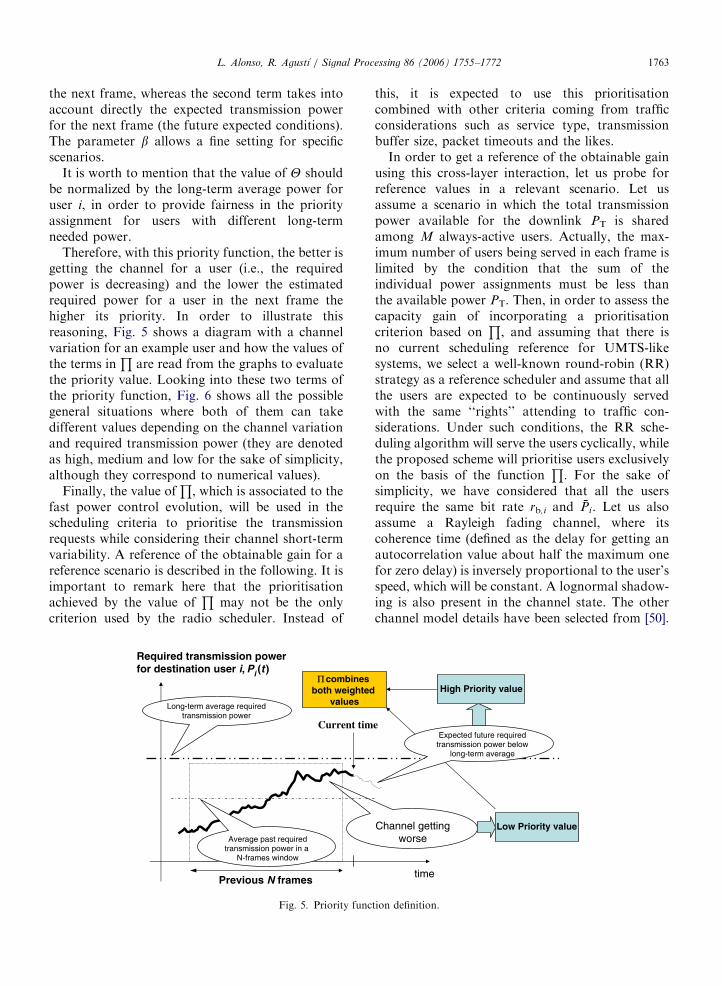
Therefore, with this priority function, the better isgetting the channel for a user (i.e., the requiredpower is decreasing) and the lower the estimatedrequired power for a user in the next frame thehigher its priority. In order to illustrate thisreasoning, Fig. 5 shows a diagram with a channelvariation for an example user and how the values ofthe terms in
Qare read from the graphs to evaluate
the priority value. Looking into these two terms ofthe priority function, Fig. 6 shows all the possiblegeneral situations where both of them can takedifferent values depending on the channel variationand required transmission power (they are denotedas high, medium and low for the sake of simplicity,although they correspond to numerical values).
Finally, the value ofQ, which is associated to the
fast power control evolution, will be used in thescheduling criteria to prioritise the transmissionrequests while considering their channel short-termvariability. A reference of the obtainable gain for areference scenario is described in the following. It isimportant to remark here that the prioritisationachieved by the value of
Qmay not be the only
criterion used by the radio scheduler. Instead of
Current tim
Required transmission powerfor destination user i, Pi (t )
Average past requiredtransmission power in a
N-frames window
Π combines both weighted
valuesLong-term average requiredtransmission power
Previous N frames
Fig. 5. Priority func
this, it is expected to use this prioritisationcombined with other criteria coming from trafficconsiderations such as service type, transmissionbuffer size, packet timeouts and the likes.
In order to get a reference of the obtainable gainusing this cross-layer interaction, let us probe forreference values in a relevant scenario. Let usassume a scenario in which the total transmissionpower available for the downlink PT is sharedamong M always-active users. Actually, the max-imum number of users being served in each frame islimited by the condition that the sum of theindividual power assignments must be less thanthe available power PT. Then, in order to assess thecapacity gain of incorporating a prioritisationcriterion based on
Q, and assuming that there is
no current scheduling reference for UMTS-likesystems, we select a well-known round-robin (RR)strategy as a reference scheduler and assume that allthe users are expected to be continuously servedwith the same ‘‘rights’’ attending to traffic con-siderations. Under such conditions, the RR sche-duling algorithm will serve the users cyclically, whilethe proposed scheme will prioritise users exclusivelyon the basis of the function
Q. For the sake of
simplicity, we have considered that all the usersrequire the same bit rate rb,i and Pi. Let us alsoassume a Rayleigh fading channel, where itscoherence time (defined as the delay for getting anautocorrelation value about half the maximum onefor zero delay) is inversely proportional to the user’sspeed, which will be constant. A lognormal shadow-ing is also present in the channel state. The otherchannel model details have been selected from [50].
e
time
Channel gettingworse
Expected future requiredtransmission power below
long-term average
High Priority value
Low Priority value
tion definition.

ARTICLE IN PRESS
01 2 3 4 5 6 7 8
5
10
15
20
25
30
35
Speed (km/h)
Gai
n (
%)
N = 5 (M = 15)
N = 5 (M = 20)
N = 10 (M = 15)
N = 10 (M = 20)
N = 100 (M = 15)
N = 100 (M = 20)
15 Users
20 Users
Fig. 7. Capacity gain of the proposed scheme versus a round-
robin strategy when b ¼ 1.
Required transmission powerfor destination user i, Pi (t )
timeLong-term average transmission power
A
A. Channel is getting worse but estimated required power is below the averageB. Channel is getting worse and estimated required power is above the averageC. Channel conditions are maintained and estimated required power is above the averageD. Channel is getting better but estimated required power is above the average
F. Channel conditions are maintained and estimated required power is above the averageE. Channel is getting better and estimated required power is below the average
Γ = LowΘ = Low
Γ = LowΘ = High
Γ = HighΘ = Low
Γ = HighΘ = High
Γ = MediumΘ = Low
Γ = MediumΘ = High
B
C
D
E
F
Fig. 6. Priority function example cases.
L. Alonso, R. Agustı / Signal Processing 86 (2006) 1755–17721764
Finally, the base station will estimate the futurevalue for the transmission power as the last known(not estimated) value of the required transmissionpower, measured from the power control mechan-ism.
Based on the described scenario, numericalsimulations have been performed in order toevaluate the gain obtained with the proposedmechanism. As stated above, we have used theRR strategy as a reference. Then, we define the gainobtained (in percentage) as the ratio between theincrease of the average number of users that actuallytransmit in each frame (using the proposed algo-rithm) and the average number of users thattransmit with the RR criterion. Calling MQ theaverage number of users transmitting with theproposal, and MRR the average number of userstransmitting with the reference RR strategy, thegain G is calculated as
Gð%Þ ¼MP �MRR
MRR100. (3)
Firstly, and in order to get a figure of the gainthat can be achieved with the proposed scheme, weconsider the case of b ¼ 1 in P, which correspondsto the case where only the channel state variation isevaluated in the prioritization function. Fig. 7shows the values of the gains obtained versus the
mobile speed, when the total power available for thedownlink is 10 times the average power needed foreach user, that is PT ¼ 10� Pi. Various curves areshown for different number of users (M ¼ 15 and20) and values of N. The carrier frequency has beenassumed to be 2GHz.
As it is clearly shown, significant gains areachieved, up to more than 30% for a low mobility

ARTICLE IN PRESSL. Alonso, R. Agustı / Signal Processing 86 (2006) 1755–1772 1765
situation. The gain obtained increases with thenumber of users as the system takes more profitfrom the multi-user diversity. On the other hand,the gain decreases with the speed of the users, as thechannel becomes more uncorrelated between con-secutive frames. As a reference value, for thescenario conditions, notice that the channel coher-ence time (defined as the delay for getting anautocorrelation value about half the maximum onefor zero delay) is about 10ms (the frame time) whenmobile’s speed is 13 km/h. Then, for speed valuesapproaching 13 km/h the channel is almost uncor-related between two consecutive frames, and thenthe priority function
Qreduces its usefulness. When
mobility is low,Q
captures the state of the channelseen by every user as well as its time variation, andthe scheduling exploits this inherent multi-userdiversity providing a significant capacity enhance-ment. Then, the proposed prioritization is especiallyuseful for indoor or outdoor pedestrian environ-ments.
Regarding the dependence on b, Fig. 8 shows theaverage delay, or equivalently, the average numberof consecutive frames each user is unable to acquirea transmission opportunity, versus b. A speed of1 km/h was selected, because the dependence on b isclearly accentuated at low speeds since channelconditions remain more stable. We can observe thatthe average transmission delay increases slightlywith b, even this increase is negligible for largevalues of N. Then, it is shown that the specificselected value for b will not affect the performanceof the mechanism.
Summarizing, this cross-layer technique makesdata transmissions to be scheduled taking intoaccount the power control information included inUMTS systems. While the channel state for each
M = 20, speed = 1km/h
12.75
13.00
13.25
beta
Ave
rag
e d
elay
(m
s)
N = 5 N = 10 N = 100 N = 200
0 0.25 0.5 0.75 1
Fig. 8. Average access delay variation versus b.
user is independent of the other users’ channel, theproposal exploits the inherent multi-user diversityand provides a significant performance improve-ment using a smart and low-complexity priorityfunction that takes into account the channel stateand channel variation of each user.
4.2. A distributed MAC protocol for cross-layering
in a CDMA environment
A great variety of medium access control (MAC)schemes have been developed and studied forwireless communication systems in the last years.Some of them are more fitted to applying cross-layermechanisms than others. In particular, those whosearchitecture is based on queues are especiallyadequate to incorporate smart scheduling to thequeues taking into account the channel state and itsvariation. Furthermore, not all the MAC protocolsare equally suited for introducing cross-layertechniques without increasing the complexity ofthe system and the control information. Among thehuge number of different MAC protocols proposedin the literature, we are to describe in detail one ofthem, which is a proposal of the authors, that fitsremarkably into cross layering. The protocol iscalled Distributed Queuing Random Access Proto-col (DQRAP/CDMA) when used in a CDMAenvironment [13,51], also called Distributed Queu-ing Collision Avoidance (DQCA) when used in aWLAN TDMA environment [52–53]. DQRAP/DQCA is a distributed always-stable high-perfor-mance protocol. It behaves as a random accessmechanism for low traffic load and switchessmoothly and automatically to a reservation schemewhen traffic load grows, so the best of eachmechanism is retained. Let us first describe theprotocol operation so that its great characteristicscould be shown. A more in depth explanation is inthe Annex.
4.2.1. MAC protocol description
Without loss of generality, let us consider N dataterminals which share a CDMA channel with K
available spreading codes to communicate with abase station (the case of a TDMA channel isincluded for K ¼ 1). The time axis is divided intoframes, and each frame has two fields. The first fieldis the access field, which is further divided into m
control minislots. The second field is the data part,where terminals will transmit their packets. Weassume that every station has perfect frame and
ARTICLE IN PRESSL. Alonso, R. Agustı / Signal Processing 86 (2006) 1755–17721766
minislot synchronisation. The K spreading codes areput in order and we will denote Ki for the ith code.We consider that the terminals are able to changethe spreading code for data and request transmis-sion on a frame-by-frame basis. The messagesgenerated by one terminal are split into frame-duration packets and put into a buffer. Each packetwill be sent with the same spreading code but not allthe packets pertaining to one message will necessa-rily be sent with the same spreading code.
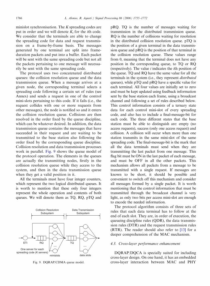
The protocol uses two concatenated distributedqueues: the collision resolution queue and the datatransmission queue. When a message arrives at agiven node, the corresponding terminal selects aspreading code following a certain set of rules (seeAnnex) and sends a request in one of the controlmini-slots pertaining to this code. If it fails (i.e., therequest collides with one or more requests fromother messages), the node is notified so and it entersthe collision resolution queue. Collisions are thenresolved in the order fixed by the queue discipline,which can be whatever desired. In addition, the datatransmission queue contains the messages that havesucceeded in their request and are waiting to betransmitted to the base station also following theorder fixed by the corresponding queue discipline.Collision resolution and data transmission processeswork in parallel. Fig. 9 shows the queue model ofthe protocol operation. The elements in the queuesare actually the transmitting nodes, firstly in thecollision resolution queue while they access to thesystem, and then in the data transmission queuewhen they get a valid position in it.
All the terminals must have four integer counters,which represent the two logical distributed queues. Itis worth to mention that these only four integersrepresent the whole operation and contents of bothqueues. We will denote them as TQ, RQ, pTQ and
ETI RQ TQ
minislots data slots
Collision ResolutionSubsystem
Data TransmissionSubsystem
... ...One server for each
spreading code (K servers)
Fig. 9. DQRAP/CDMA queue model.
pRQ. TQ is the number of messages waiting fortransmission in the distributed transmission queue.RQ is the number of collisions waiting for resolutionin the distributed collision resolution queue. pTQ isthe position of a given terminal in the data transmis-sion queue and pRQ is the position of that terminal inthe collision resolution queue. These values rangefrom 0, meaning that the terminal does not have anyposition in the corresponding queue, to TQ or RQ(respectively). The value i indicates the ith position ofthe queue. TQ and RQ have the same value for all theterminals in the system (i.e., they represent distributed
queues), while pTQ and pRQ have a specific value foreach terminal. All four values are initially set to zeroand must be kept updated using feedback informationsent by the base station each frame, using a broadcastchannel and following a set of rules described below.This control information consists of a ternary statedata for each control mini-slot of every spreadingcode, and also has to include a final-message-bit foreach code. The three different states that the basestation must be able to distinguish are: empty (noaccess requests), success (only one access request) andcollision. A collision will occur when more than onestation transmits in the same mini-slot of the samespreading code. The final-message-bit is the mark thatall the data terminals must send when they aretransmitting the last packet from one message. Thisflag bit must be ON in the last packet of each message,and must be OFF in all the other packets. Thismechanism allows all packets from a message to betransmitted with a single request. If messages areknown to be short, it should be possible andconvenient to switch off this mechanism and considerall messages formed by a single packet. It is worthmentioning that the control information that must betransmitted through the broadcast channel is verylight, as only two bits per access mini-slot are enoughto encode the needed information.
The protocol algorithm consists of three sets ofrules that each data terminal has to follow at theend of each slot. They are, in order of execution, thequeueing discipline rules (QDR), the data transmis-sion rules (DTR) and the request transmission rules(RTR). The reader should also refer to [13] for adeeper comprehension of the MAC mechanism.
4.3. Cross-layer performance enhancement
DQRAP/DQCA is specially suited for includingcross-layer design. On one hand, it has an embeddedcross-layer interaction between MAC and PHY
ARTICLE IN PRESS
0
100
200
300
400
500
600
0 100 200 300 400 500 600 700 800 900 1000
Offered load (Kbps)
ms
64Kbps 128Kbps 256Kbps
512Kbps Rate adaptation
Fig. 11. Average packet delay considering different rate selection
schemes using cross-layer information.
4FTM Power independent NFTM Power dependent
L. Alonso, R. Agustı / Signal Processing 86 (2006) 1755–1772 1767
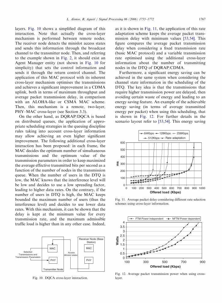
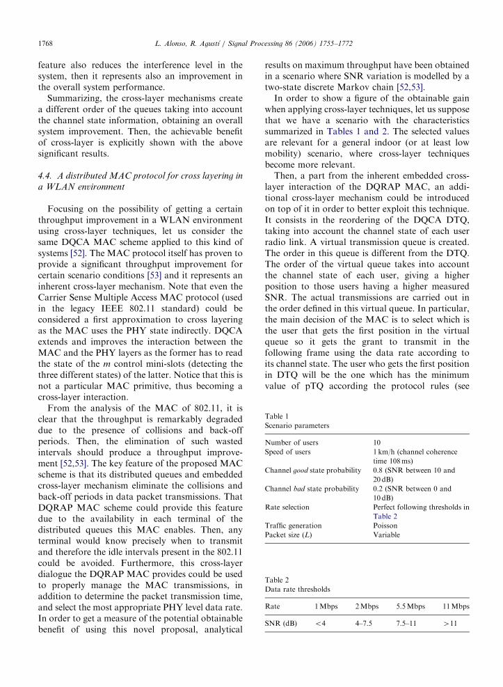
layers. Fig. 10 shows a simplified diagram of thisinteraction. Note that actually the cross-layermechanism is performed between remote nodes.The receiver node detects the minislot access statesand sends this information through the broadcastchannel to the transmitter node. Then, and referringto the example shown in Fig. 2, it should exist anAgent Manager entity (not shown in Fig. 10 forsimplicity) that sets the control information andsends it through the return control channel. Theapplication of this MAC protocol with its inherentcross-layer mechanism optimises the transmissionsand achieves a significant improvement in a CDMAuplink, both in terms of maximum throughput andaverage packet transmission delay, in comparisonwith an ALOHA-like or CSMA MAC scheme.Then, this mechanism is a remote, two-layer,PHY–MAC cross-layer (see Section 3.3).
On the other hand, as DQRAP/DQCA is basedon distributed queues, the application of appro-priate scheduling strategies in the queuing disciplinerules taking into account cross-layer informationmay allow achieving an even higher significantimprovement. The following additional cross-layerinteraction has been proposed: in each frame, theMAC decides the optimum number of simultaneoustransmissions and the optimum value of thetransmission parameters in order to keep maximizedthe average effective transmitted bits per second as afunction of the number of nodes in the transmissionqueue. When the number of users in the DTQ islow, the MAC knows that the interference level willbe low and decides to use a low spreading factor,leading to higher data rates. On the contrary, if thenumber of users in DTQ is high, the MAC keepsbounded the maximum number of users (thus theinterference level) and decides to use lower datarates. With this mechanism, it can be shown that thedelay is kept at the minimum value for everytransmission rate, and the maximum admissibletraffic load is higher than in any other case. Indeed,
Receiver Node (BaseStation)
Transmitter Node
MAC
PHY
SelectedTransmissions and
Transmission Parameters
MAC
PHY
AccessMinislot states
Fig. 10. DQCA cross-layer interaction.
as it is shown in Fig. 11, the application of this rateadaptation scheme keeps the average packet trans-mission delay with minimum values [53,54]. Thisfigure compares the average packet transmissiondelay when considering a fixed transmission rate(basic MAC protocol) and a variable transmissionrate optimised using the additional cross-layerinformation about the number of transmittingnodes in the DTQ of DQRAP/CDMA.
Furthermore, a significant energy saving can beachieved in the same system when considering thechannel state information in the scheduling of theDTQ. The key idea is that the transmissions thatrequire higher transmission power are delayed, thenavoiding certain waste of energy and leading to anenergy saving feature. An example of the achievableenergy saving (in terms of average transmittedenergy per packet) when using this scheduling, thatis shown in Fig. 12. For further details in thescenario layout refer to [53,54]. This energy saving
00.5
11.5
22.5
33.5
100 300 500 700 900Offered load (Kbps)
Wat
ts
Fig. 12. Average packet transmission power when using cross-
layer.
ARTICLE IN PRESS
Table 1
Scenario parameters
Number of users 10
Speed of users 1 km/h (channel coherence
time 108ms)
Channel good state probability 0.8 (SNR between 10 and
20 dB)
Channel bad state probability 0.2 (SNR between 0 and
10 dB)
Rate selection Perfect following thresholds in
Table 2
Traffic generation Poisson
Packet size (L) Variable
Table 2
Data rate thresholds
Rate 1Mbps 2Mbps 5.5Mbps 11Mbps
SNR (dB) o4 4–7.5 7.5–11 411
L. Alonso, R. Agustı / Signal Processing 86 (2006) 1755–17721768
feature also reduces the interference level in thesystem, then it represents also an improvement inthe overall system performance.
Summarizing, the cross-layer mechanisms createa different order of the queues taking into accountthe channel state information, obtaining an overallsystem improvement. Then, the achievable benefitof cross-layer is explicitly shown with the abovesignificant results.
4.4. A distributed MAC protocol for cross layering in
a WLAN environment
Focusing on the possibility of getting a certainthroughput improvement in a WLAN environmentusing cross-layer techniques, let us consider thesame DQCA MAC scheme applied to this kind ofsystems [52]. The MAC protocol itself has proven toprovide a significant throughput improvement forcertain scenario conditions [53] and it represents aninherent cross-layer mechanism. Note that even theCarrier Sense Multiple Access MAC protocol (usedin the legacy IEEE 802.11 standard) could beconsidered a first approximation to cross layeringas the MAC uses the PHY state indirectly. DQCAextends and improves the interaction between theMAC and the PHY layers as the former has to readthe state of the m control mini-slots (detecting thethree different states) of the latter. Notice that this isnot a particular MAC primitive, thus becoming across-layer interaction.
From the analysis of the MAC of 802.11, it isclear that the throughput is remarkably degradeddue to the presence of collisions and back-offperiods. Then, the elimination of such wastedintervals should produce a throughput improve-ment [52,53]. The key feature of the proposed MACscheme is that its distributed queues and embeddedcross-layer mechanism eliminate the collisions andback-off periods in data packet transmissions. ThatDQRAP MAC scheme could provide this featuredue to the availability in each terminal of thedistributed queues this MAC enables. Then, anyterminal would know precisely when to transmitand therefore the idle intervals present in the 802.11could be avoided. Furthermore, this cross-layerdialogue the DQRAP MAC provides could be usedto properly manage the MAC transmissions, inaddition to determine the packet transmission time,and select the most appropriate PHY level data rate.In order to get a measure of the potential obtainablebenefit of using this novel proposal, analytical
results on maximum throughput have been obtainedin a scenario where SNR variation is modelled by atwo-state discrete Markov chain [52,53].
In order to show a figure of the obtainable gainwhen applying cross-layer techniques, let us supposethat we have a scenario with the characteristicssummarized in Tables 1 and 2. The selected valuesare relevant for a general indoor (or at least lowmobility) scenario, where cross-layer techniquesbecome more relevant.
Then, a part from the inherent embedded cross-layer interaction of the DQRAP MAC, an addi-tional cross-layer mechanism could be introducedon top of it in order to better exploit this technique.It consists in the reordering of the DQCA DTQ,taking into account the channel state of each userradio link. A virtual transmission queue is created.The order in this queue is different from the DTQ.The order of the virtual queue takes into accountthe channel state of each user, giving a higherposition to those users having a higher measuredSNR. The actual transmissions are carried out inthe order defined in this virtual queue. In particular,the main decision of the MAC is to select which isthe user that gets the first position in the virtualqueue so it gets the grant to transmit in thefollowing frame using the data rate according toits channel state. The user who gets the first positionin DTQ will be the one which has the minimumvalue of pTQ according the protocol rules (see

ARTICLE IN PRESS
00 1 2 3 4 5 6 7 8
10
20
30
40
50
60
70
80
90
100
Offered Load (Mbps)
Ave
rag
e d
elay
(m
s)
L = 100 bytes No Cross-layer
L = 100 bytes Cross-layer
L = 570 bytes No Cross-layer
L = 570 bytes Cross-layer
L = 2312 bytes No Cross-layer
L = 2312 bytes Cross-layer
τc = 108 ms
Fig. 14. Obtainable gain in terms of transmission delay when applying cross-layer techniques.
00 1 2 3 4 5 6 7 8 9 10 11 12
1
2
3
4
5
6
7
8
9
10
11
Offered Load (Mbps)
Th
rou
gh
pu
t (M
bp
s)
L = 100 bytes No Cross-Layer
L = 100 bytes 802.11
L = 570 bytes 802.11
L = 100 bytes Cross-Layer
L = 570 bytes No Cross-Layer
L = 2312 bytes No Cross-Layer
L = 2312 bytes Cross-Layer
L = 2312 bytes 802.11
L = 570 bytes Cross-Layer
τc = 108 ms
Fig. 13. Obtainable gain in terms of throughput when applying cross-layer techniques.
L. Alonso, R. Agustı / Signal Processing 86 (2006) 1755–1772 1769
Section 4.2) among those with the better channelconditions (i.e. the higher SNR threshold). Then, wepropose to have a transmitting user with the fasterrate from the available ones. This techniqueoptimises the channel overall efficiency.
With these conditions, Figs. 13 and 14 show,respectively, the comparison of the throughput and
transmission delay when using this cross-layertechnique with respect to the case of the legacyMAC procedure. The reference throughput valuefor a system using 802.11 is also plotted inFig. 13, showing the potential benefits provided bythese proposals, both in terms of delay andthroughput.

ARTICLE IN PRESSL. Alonso, R. Agustı / Signal Processing 86 (2006) 1755–17721770
It can be shown that a significant throughput gaincan be obtained (up to 77% for packets of 2312bytes) when applying the deeper cross-layer me-chanism, and even the legacy protocol, which has aninherent cross-layer assumption, provides a relevantenhancement. Furthermore, as the channel is usedmore efficiently, the average packet transmissiondelay is also slightly reduced. Even more, if can beshown that this improvement is achieved withoutpaying any cost in the fairness of the transmissions,as the variance of the packet delay is not increased.Obviously, this is true if the channel variation ofeach users is independent from the channel varia-tion of the other users. In short, the key idea of thisenhancement is that the MAC protocol and thecross-layer mechanism almost eliminate the wastedinactive periods of the legacy standard. The CSIinformation read from the PHY layer by the MACleads the algorithm to conveniently order thetransmissions, optimizing the channel efficiencywhile selecting the best transmission option amongthe available set. This is performed due to the smartscheduling that creates a virtual queue whoseordering depends on the channel conditions, thatis, the nodes with better channel conditions are‘pushed’ to the top of the queue.
Then, this example clearly shows the vast field ofexploration of the enhancements that can arise fromthe use of cross layering in wireless communicationssystems.
5. Conclusions
Cross-layer techniques where different layers ofwireless communications systems interchange con-trol information in order to optimise the use of thescarce radio resources are a wide relatively unex-plored research area where huge potential benefitscan be achieved. The interaction between PHY andMAC layers has been the first explored issue in thisarea and it has shown a first set of possibleenhancements. For example, while the channel statein a multi-user environment is independent for eachone of the users, cross layering can exploit theinherent multi-user diversity and provide a signifi-cant performance improvement. Average transmis-sion delay reduction, energy saving and QoSfeatures are only a few of the possible achievablebenefits. This paper has outlined some examples ofthe recent results in this research area for severalrepresentative scenarios and then it foresees the
importance of keeping investing efforts in thisdirection so higher enhancements can be arisen.
Acknowledgments
The authors want to highly appreciate thesupport provided by COSMOS project, which isfunded by Spanish CICYT (Ref. TEC2004-00518).
References
[1] D. Wetteroth, OSI Reference Model for Telecommunica-
tions, McGraw-Hill, New York, 2001.
[2] T.S. Rappaport, A. Annamalai, R.M. Buehrer, W.H.
Tranter, Wireless communications: past events and a future
perspective, IEEE Comm. Mag., 50th Anniversary Com-
memorative Issue, May 2002.
[3] M. Zorzi, R.R. Rao, Error control and energy consumption
in communications for nomadic computing, IEEE Trans.
Comput. 46 (March 1997) 279–289.
[4] C. Chien, M. Srivastava, R. Jain, P. Lettieri, R. Sternowski,
Adaptive radio for multimedia wireless links, IEEE J. Select.
Areas Comm. 17 (5) (May 1999) 793–813.
[5] C. Liu, H. Asada, A source coding and modulation method
for power saving and interference reduction in DS-CDMA
sensor network systems, Proc. Amer. Control Conf. 4 (2002)
3003–3008.
[6] B.S. Tsybakov, N.B. Likhanov, Upper bound on the
capacity of a random multiple access system, Problems
Inform.Transmission 23 (3) (September 1987) 224–236.
[7] M.J. Karol, Z. Liu, K.Y. Eng, Distributed-queueing request
update multiple access (DQRUMA) for wireless packet
(ATM) networks, in: Proceedings of the ICC’95, Seattle,
WA. pp. 1224–1231.
[8] E. Nikula, A. Toskala, E. Dalhman, L. Girard, A. Klein,
FRAMES multiple access for UMTS and IMT-2000,, IEEE
Pers. Comm. (April 1998) 16–24.
[9] T. Towsley, P.O. Vales, Announced arrival random access
protocols, IEEE Trans. Comm. COM-35 (5) (May 1987)
513–521.
[10] J. Perez-Romero, R. Agusti, O. Sallent, An adaptive ISMA-
DS/CDMA MAC protocol for third-generation mobile
communications systems, IEEE Trans. Vehicular Technol.
50 (6) (November 2001) 1354–1365.
[11] S.S. Lam, Packet broadcast networks—a performance
analysis of the R-ALOHA protocol, IEEE Trans. Comput.
C-29 (7) (July 1980) 596–603.
[12] S. Nanda, D.J. Goodman, U. Timor, Performance of
PRMA: a packet voice protocol for cellular systems, IEEE
Trans. Vehicular Technol. 40 (3) (August 1991) 584–598.
[13] L. Alonso, R. Agusti, O. Sallent, A near-optimum MAC
protocol based on the distributed queueing random access
protocol (DQRAP) for a CDMA mobile communication
system, IEEE J. Select. Areas Comm. 18 (9) (September
2000) 1701–1718.
[14] J.M. Hanratty, G.L. Stuber, Performance analysis of hybrid
ARQ protocols in a slotted direct sequence code-division
multiple-access network: jamming analysis, IEEE J. Select.
Areas Comm. 8 (May 1990) 562–579.

ARTICLE IN PRESSL. Alonso, R. Agustı / Signal Processing 86 (2006) 1755–1772 1771
[15] J. Perez-Romero, R. Agusti, O. Sallent, Analysis of a type II
hybrid ARQ strategy in a DS-CDMA packet transmission
environment, IEEE Trans. Comm. 51 (8) (August 2003)
1249–1253.
[16] S. Kallel, D. Haccoun, Sequential decoding with ARQ and
code combining: a robust hybrid FEC/ARQ system, IEEE
Trans. Commun. 36 (7) (July 1988) 773–780.
[17] P. Lettieri, C. Schurgers, M. Srivastava, Adaptive link layer
strategies for energy efficient wireless networking, Wireless
Networks 5 (5) (October 1999) 339–355.
[18] E. Ayanoglu, S. Paul, T.F. LaPorta, K.K. Sabnani, R.D.
Gitlin, AIRMAIL: a link-layer protocol for wireless net-
works, Wireless Networks 1 (1) (February 1995) 47–60.
[19] W. Gang, K. Taira, K. Mukumoto, et al., A mixed channel
access and hybrid ARQ method for wireless communication
networks, in: Proceedings of ICUPC ‘95–Fourth IEEE
International Conference on Universal Personal Commu-
nications, Tokyo, Japan, 6–10 November 1995, pp. 707–712.
[20] P.-J. Wan, G. Calinescu, C.-W. Yi, Minimum-power multi-
cast routing in static ad hoc wireless networks, IEEE/ACM
Trans. Networking 12 (3) (June 2004) 507–514.
[21] A. Tsirigos, Z.J. Haas, Analysis of multipath routing, part 2:
mitigation of the effects of frequently changing network
topologies, IEEE Trans. Wireless Comm. 3 (2) (March 2004)
500–511.
[22] C.-F. Chiasserini, M. Meo, A reconfigurable protocol setting
to improve TCP over wireless, IEEE Trans. Vehicular
Technol. 51 (6) (November 2002) 1608–1620.
[23] Q. Wang, M.A. Abu-Rgheff, Cross-layer signalling for next-
generation wireless systems, in: IEEE WCNC 2003, vol. 2,
March 2003, pp. 1084–1089.
[24] E. Yeh, A. Cohen, A fundamental cross-layer approach to
uplink resource allocation, IEEE MILCOM 2003, vol. 1,
October 2003, pp. 699–704.
[25] W. H. Yuen, H.-n. Lee, T.D. Andersen, A simple and
effective cross layer networking system for mobile ad hoc
networks, in: PIMRC 2002, vol. 4, September 2002, pp.
1952–1956.
[26] M. van der Schaar, S. Krishnamachari, S. Choi, X. Xu,
Adaptive cross-layer protection strategies for robust scalable
video transmission over 802.11 WLANs,, IEEE J. Selected
Areas Comm. 21 (10) (December 2003) 1752–1763.
[27] L.T. Berger, T.E. Kolding, J. Ramiro-Moreno, P. Amei-
geiras, L. Schumacher, P.E. Mogensen, Interaction of
transmit diversity and proportional fair scheduling, IEEE
VTC Spring 2003, vol. 4, April 2003, pp. 2423–2427.
[28] S. Shakkottai, T.S. Rappaport, P.C. Karlsson, Cross-layer
design for wireless networks, IEEE Comm. Mag. 41 (10)
(October 2003) 74–80.
[29] G. Carneiro, J. Ruela, M. Ricardo, Cross-layer design in 4G
wireless terminals, IEEE Wireless Comm. 11 (2) (April 2004)
7–13.
[30] V.T. Raisinghania, B.S. Iyer, Cross-layer design optimiza-
tions in wireless protocol stacks, Computer Comm. (27)
(2004) 720–724.
[31] A. Maharshi, L. Tong, A. Swami, Cross-layer designs of
multichannel reservation MAC under Rayleigh fading,
IEEE Trans. Signal Process. 51 (8) (August 2003).
[32] K. Kyamakya, Van Duc Nguyen, Cross-layer optimization,
especially combination of channel estimation and position
determination in multihop wireless networks (cellular and
adhoc), in: VTC 2003-Fall, vol. 3, 2003, pp. 1537–1543.
[33] Y. Fang, A.B. McDonald, Cross-layer performance effects
of path coupling in wireless ad hoc networks: power and
throughput implications of IEEE 802.11 MAC, in: PCCC
2002, April 2002, pp. 281–290.
[34] S.A. Khoyam, S. Karande, M. Krappel, H. Radha, Cross-
layer protocol design for real-time multimedia applications
over 802.11b networks, in: ICME ‘03, vol. 2, July 2003,
pp. 425–428.
[35] E. Yeh, Delay-optimal rate allocation in multiaccess
communications: a cross-layer view, in: IEEE Workshop
on Multimedia Signal Processing, vol. 1, December 2002,
pp. 404–407.
[36] N. Reijers, K. Langendoen, Efficient code distri-
bution in wireless sensor networks, in: WSNA’03,
19 September 2003, San Diego, California, USA, pp.
60–67
[37] Y.K. Kwok, V.K. Lau, Efficient multiple access control
using a channel adaptive protocol for a wireless ATM-based
multimedia services network, Comput. Comm. 24 (10)
(October 2001) 970–983.
[38] S. Biaz, Y. Dai Barowski, GANGS: an energy efficient MAC
protocol for sensor networks, in: ACMSE’04, April 2004,
Huntsville, Alabama, USA, pp. 82–87.
[39] G. Barriac, J. Holtzman, Introducing delay sensitivity into
the proportional fair algorithm for CDMA downlink
scheduling, in: IEEE Seventh International Symposium on
Spread Spectrum Techniques and Applications, vol. 3, 2002,
pp. 652–656.
[40] L. Tong, Q. Zhao, G. Mergen, Multipacket reception in
random access wireless networks: from signal processing to
optimal medium access control, IEEE Comm. Mag. 39 (11)
(November 2001) 108–112.
[41] X. Alec Woo, S. Madden, R. Govindan, Networking
support for query processing in sensor networks, Comm.
ACM 47 (6) (June 2004) 45–47.
[42] Y.S. Chan, Y. Pei, Q. Qu, J.W. Modestino, On cross-layer
adaptivity and optimization for multimedia CDMA mobile
wireless networks, in: First International Symposium on
Control, Communications and Signal Processing, March
2004, pp. 579–582.
[43] M.-L. Shyu, S.-C. Chen, H. Luo, Optimal bandwidth
allocation scheme with delay awareness in multi-
media transmission, in: ICME’02, vol. 1, August 2002,
pp. 37–540.
[44] A. Fu, E. Modiano, J. Tsitsiklis, Optimal energy allocation
for delay-constrained data transmission over a time-varying
channel, INFOCOM 2003, vol. 2, March–April 2003,
pp. 1095–1105.
[45] X. Liu, A.J. Goldsmith, Optimal power allocation over
fading channels with stringent delay constraints, in: ICC
2002, vol. 3, April–May 2002, pp. 1413–1418.
[46] S. Toumpis, A.J. Goldsmith, Performance, optimization,
and Cross-Layer design of media access protocols for
wireless ad hoc networks, in: ICC’03, vol. 3, May 2003,
pp. 2234.
[47] J. Zhao, Z. Guo, W. Zhu, Power efficiency in IEEE 802.11a
WLAN with cross-layer adaptation, in: ICC’03, vol. 3, May
2003, pp. 2030–2034.
[48] X. Wang, Wide-band TD-CDMA MAC with minimum-
power allocation and rate- and BER-scheduling for wireless
multimedia networks, IEEE/ACM Trans. Networking 12 (1)
(February 2004) 103–116.
ARTICLE IN PRESSL. Alonso, R. Agustı / Signal Processing 86 (2006) 1755–17721772
[49] M. Park, J.G. Andrews, S.M. Nettles, Wireless channel-
aware ad hoc cross-layer protocol with multi-route path
selection diversity, in: VTC 2003-Fall, vol. 4, October 2003,
pp. 2197–2201.
[50] G.L. Stuber, Principles of Mobile Communication, second
ed, Kluwer Academic, Dordrechnt, 2001.
[51] W. Xu, G. Campbell, DQRAP–a distributed que-
ueing random access protocol for a broadcast cha-
nnel, in: SIGCOMM ‘93, San Francisco, 14 September
1993; Comput. Comm. Rev. 23, (4) (1993 October)
270–278.
[52] L. Alonso, R. Ferrus, R. Agustı, WLAN throughput
improvement via distributed queuing MAC, IEEE Comm.
Lett. 9 (4) (April 2005) 310–312.
[53] L. Alonso, R. Ferrus, R. Agustı, MAC–PHY enhancement
for 802.11b WLAN systems via cross-layering, in: IEEE
VTC’03 Fall, Orlando, September 2003.
[54] L. Alonso, R. Agustı, Automatic rate adaptation and
energy-saving mechanisms based on cross-layer information
for packet-switched data networks, IEEE Comm. Mag. 43
(3) (March 2004) S15–S20.
[55] NewCom (FP6 NoE) DRE.1
[56] H. Holma, A. Toskala (Eds.), WCDMA for UMTS Radio
Access for Third Generation Mobile Communications,
second ed, Wiley, New York, 2002.
[57] http://www.ist-4more.org.
[58] http://www.ist-phoenix.org.
[59] http://newcom.ismb.it.


![The MAC layer in wireless networks - unibo.it · The MAC layer in wireless networks The wireless MAC layer roles ... MACA [Karn1990]: ... "MACAW: A Media Access Protocol for …](https://img.pdfslide.net/doc/110x75/5b5b7a167f8b9a302a8e0f73/the-mac-layer-in-wireless-networks-uniboit-the-mac-layer-in-wireless-networks.jpg)