Embed Size (px)
Citation preview

12
Optimized 3D Network-on-Chip Design Using Simulated Allocation
PINGQIANG ZHOU, University of MinnesotaPING-HUNG YUH, National Taiwan UniversitySACHIN S. SAPATNEKAR, University of Minnesota
Three-dimensional (3D) silicon integration technologies have provided new opportunities for Network-on-Chip (NoC) architecture design in Systems-on-Chip (SoCs). In this article, we consider the application-specific NoC architecture design problem in a 3D environment. We present an efficient floorplan-aware 3DNoC synthesis algorithm based on simulated allocation (SAL), a stochastic method for traffic flow routing,and accurate power and delay models for NoC components. We demonstrate that this method finds greatlyimproved solutions compared to a baseline algorithm reflecting prior work. To evaluate the SAL method, wecompare its performance with the widely used simulated annealing (SA) method and show that SAL is muchfaster than SA for this application, while providing solutions of very similar quality. We then extend theapproach from a single-path routing to a multipath routing scheme and explore the trade-off between powerconsumption and runtime for these two schemes. Finally, we study the impact of various factors on thenetwork performance in 3D NoCs, including the TSV count and the number of 3D tiers. Our studies showthat link power and delay can be significantly improved when moving from a 2D to a 3D implementation,but the improvement flattens out as the number of 3D tiers goes beyond a certain point.
Categories and Subject Descriptors: B.7.2 [Integrated Circuits]: Design Aids
General Terms: Algorithms, Design, Performance
Additional Key Words and Phrases: 3D, NoC, application-specific, simulated allocation
ACM Reference Format:Zhou, P., Yuh, P.-H., and Sapatnekar, S. S. 2012. Optimized 3D network-on-chip design using simulatedallocation. ACM Trans. Des. Autom. Electron. Syst. 17, 2, Article 12 (April 2012), 19 pages.DOI = 10.1145/2159542.2159544 http://doi.acm.org/10.1145/2159542.2159544
1. INTRODUCTION
Three-dimensional (3D) integrated circuits, in which multiple tiers are stacked aboveeach other and vertically interconnected using through-silicon vias (TSVs), are emerg-ing as a promising technology for SoCs [Banerjee et al. 2001; Davis et al. 2005; Lim2005; Xue et al. 2003]. As compared to 2D designs, 3D circuits permit reduced latenciesfor critical interconnect structures, resulting in higher system throughput, perfor-mance, and power, and allowing other benefits, such as heterogeneous integration. Allof these flexibilities enable the design of new, high-performance System-on-Chip (SoC)structures that were previously thought to have prohibitive overheads. In spite of well-
This work was supported in part by the SRC under contract 2008-TJ-1819.Some initial results of this article are published in Proceedings of the Annual Asia and South Pacific DesignAutomation Conference [Zhou et al. 2010].Authors’ addresses: P. Zhou and S. S. Sapatnekar, Electrical and Computer Engineering Department, Uni-versity of Minnesota; email: [email protected]; P.-H. Yuh, Computer Science and Information Engineer-ing Department, National Taiwan University.Permission to make digital or hard copies of part or all of this work for personal or classroom use is grantedwithout fee provided that copies are not made or distributed for profit or commercial advantage and thatcopies show this notice on the first page or initial screen of a display along with the full citation. Copyrightsfor components of this work owned by others than ACM must be honored. Abstracting with credit is permit-ted. To copy otherwise, to republish, to post on servers, to redistribute to lists, or to use any component ofthis work in other works requires prior specific permission and/or a fee. Permissions may be requested fromthe Publications Dept., ACM, Inc., 2 Penn Plaza, Suite 701, New York, NY 10121-0701, USA, fax +1 (212)869-0481, or [email protected]© 2012 ACM 1084-4309/2012/04-ART12 $10.00
DOI 10.1145/2159542.2159544 http://doi.acm.org/10.1145/2159542.2159544
ACM Transactions on Design Automation of Electronic Systems, Vol. 17, No. 2, Article 12, Publication date: April 2012.

12:2 P. Zhou et al.
known challenges, such as thermal bottlenecks (to which several solutions have beenproposed), the benefits of 3D integration are considerable. In the context of intrachipcommunication, 3D technologies have created significant opportunities and challengesin the design of low-latency, low-power, and high-bandwidth interconnection networks.
In 2D SoCs, choked by interconnect limitations, networks-on-chip (NoCs), composedof switches and links, have been proposed as a scalable solution to the global com-munication challenges. Compared to previous architectures for on-chip communica-tion, such as bus-based and point-to-point networks, NoCs have been shown to providebetter predictability, lower power consumption, and greater scalability [Benini andMicheli 2002; Dally and Towles 2001].
3D circuits enable the design of more complex and more highly interconnected sys-tems. In this context, NoCs promise major benefits but impose new constraints andlimitations. Compared to wire interconnects, NoCs not only enable scalable and par-allel communication within and across 3D tiers but also reduce the number of TSVsfor vertical interconnects. However, 3D NoC design introduces new issues, such asthe technology constraints on the number of TSVs that can be supported, problemsrelated to optimally determining tier assignments, and the placement of switches in3D circuits, and accurate power and delay modeling issues for 3D interconnects.
This work addresses the problem of designing application-specific 3D NoC architec-tures for custom SoC designs in conjunction with floorplanning. Specifically, our workdetermines both the NoC topology and the floorplan of the NoC switches and cores. Wepropose a synthesis method to find the best topology for the application under differentoptimization objectives, such as power and network latency, and determine the pathsfor traffic flows. We use a 3D, thermally aware floorplanner to assign the cores todifferent 3D tiers while optimizing chip temperature and find an initial floorplan forthe cores on each tier. Given the positions of cores, we use a stochastic flow allocationmethod, Simulated Allocation (SAL), to route the traffic flows and build the topologyfor the application, initially using a simple strategy for determining the approximatelocations of the switches. When the best topology is found, a fast floorplanner isapplied to further optimize the positions of the added switches. Accurate power anddelay models for switches and links are integrated into our algorithm.
Our approach has three significant features that together make it uniquely differ-ent from competing approaches. First, we use improved traffic flow routing using SALthat accommodates a realistic objective function that has components that are nonlin-ear and/or unavailable in closed form. Second, we interleave floorplanning with NoCsynthesis, using specific measures that encourage convergence by discouraging blocksfrom moving from their locations in each iteration. Third, we use an accurate NoCdelay model that incorporates the effects of queueing delays and network contention.
NoC synthesis can be based on either single-path or multipath routing: single-pathrouting can guarantee in-order delivery of packets and is much simpler to implement;multipath routing can exploit path diversity to evenly distribute the traffic acrossthe network and to relieve traffic congestion, but the packets are sent in out-of-orderfashion and re-ordering mechanisms are needed at the reconvergent nodes [Muraliet al. 2006]. We demonstrate that our SAL approach can work with either single-pathor multipath routing schemes.
Our algorithm is extremely flexible and is applicable to both 2D and 3D layouts, butwe demonstrate that the use of 3D designs results in significantly reduced NoC powerand latency, as compared to optimal 2D implementations.
2. CONTRIBUTIONS OF OUR WORK
There has been a great deal of prior work on NoCs alone and on 2D and 3D layout alonebut less on integrating the two. In the area of designing NoC architectures for 3D ICs,
ACM Transactions on Design Automation of Electronic Systems, Vol. 17, No. 2, Article 12, Publication date: April 2012.

Optimized 3D Network-on-Chip Design Using Simulated Allocation 12:3
most of the literature has focused on regular 3D NoC topologies, such as meshes [Addo-Quaye 2005; Feero and Pande 2007; Kim et al. 2007; Matsutani et al. 2007; Pavlidisand Friedman 2007], which are appropriate for regular 3D designs [Li et al. 2006;Morrow et al. 2007]. However, most modern SoC architectures consist of heteroge-nous cores, such as CPU or DSP modules, video processors, and embedded memoryblocks, and the traffic requirements among the cores can vary widely. Therefore, regu-lar topologies, such as meshes, may have significant area and power overhead [Muraliet al. 2009; Yan and Lin 2008b], and tuning the topology for application-specific solu-tions can provide immense benefits.
The synthesis of an application-specific NoC topology includes finding the optimalnumber and size of switches, establishing the connectivity between the switches andwith the cores, and finding deadlock-free routing paths for all the traffic flows. For2D systems, the problem of designing application-specific NoC topologies has been ex-plored by several researchers [Ahonen et al. 2004; Hansson et al. 2005; Murali et al.2006; Srinivasan et al. 2005; Yan and Lin 2008a]. Srinivasan et al. [2005] present athree-phase NoC synthesis technique consisting of sequential steps that floorplan thecores, then perform core-to-router mapping, and finally generate the network topology.Murali et al. [2006] present an NoC synthesis method that incorporates the floorplan-ning process to estimate link power consumption and detect timing violations. Severaltopologies, each with a different number of switches, are explored—starting from onewhere all the cores are connected to one switch, to one where each core is connected toa separate switch. The traffic flows are ordered so that larger flows are routed first.
In the 3D domain, Yan and Lin [2008b] present an application-specific 3D NoC syn-thesis algorithm that is based on a rip-up-and-reroute procedure for routing flows inwhich the traffic flows are ordered in the order of increasing rate requirements so thatsmaller flows are routed first, followed by a router merging procedure. Murali et al.[2009] propose a 3D NoC topology synthesis algorithm, which is an extension to theirprevious 2D work [Murali et al. 2006], previously described. The 3D NoC synthesisproblem has been shown to be NP-hard in Seiculescu et al. [2009].
Our work is motivated by the following observations.
— The final results of application-specific NoC topology synthesis depend on the orderin which the traffic flows are routed. In some cases, routing larger flows first pro-vides better results [Hansson et al. 2005; Murali et al. 2006], while in others, routingthe smaller flows first may yield better results [Yan and Lin 2008b]. A strategy isrequired to reduce the dependency of the results on flow ordering.
— In all of the works mentioned previously, the average hop count is used to approx-imate the average packet latency in NoCs. This ignores the queueing delays inswitch ports and the contention among different packets for network resources,such as switch ports and physical links, and cannot reflect the impact of physicalcore-to-switch or switch-to-switch distances on network latency. More accurate de-lay models (that include the effects of queueing delay and network contention) andbetter delay metrics should be applied for NoC performance analysis.
— The delays and power dissipation for physical links in NoCs are closely linked tothe physical floorplan and topology of cores and switches. We show in Section 6 thatinterleaving floorplanning and the NoC topology synthesis process lead to superiorresults.
We address these important problems in application-specific NoC topology syn-thesis. Our solution to overcoming the ordering problem is based on the use of amulticommodity flow network formulation for the NoC synthesis problem. The advan-tage of such an approach is that it takes a global view of the problem and eliminates
ACM Transactions on Design Automation of Electronic Systems, Vol. 17, No. 2, Article 12, Publication date: April 2012.

12:4 P. Zhou et al.
the problem, previously described, of finding the best order in which to route thetraffic flows. The multicommodity flow problem is a well-known approach for solvingsuch problems but has seen little use in NoC design, with a few exceptions. Hu et al.[2005, 2006] propose a scheme to optimize NoC power consumption through topologyexploration and wire-style optimization, subject to the average communication latencyconstraints. Their scheme, however, does not handle layout synthesis issues andassumes simple linear objective functions.
Our work utilizes a stochastic SAL approach to efficiently solve the multicommodityflow problem under a nonlinear objective function that can be evaluated by an oraclebut is hard to express in closed form. The SAL framework has previously beenused to solve multicommodity flow problems in computer network design. We alsouse an accurate delay model for switches in NoCs which considers the queueingdelay and network contention. Finally, our algorithm performs the floorplanning ofcores/switches and NoC topology synthesis in an integrated iterative loop, attemptingto find the optimal solution for the problem of application-specific NoC design.
Our work targets SoC applications, which have static or semi-static traffic char-acteristics in the network. Dynamic traffic behaviors are observed in the many-coreprocessors, but such applications are beyond the scope of this article. In the contextof synthesizing application-specific 3D NoC architectures for custom SoC designs, thisarticle makes the following contributions.
— We present an efficient floorplan-aware 3D NoC synthesis algorithm based on simu-lated allocation, a stochastic method for traffic flow routing, and accurate power anddelay models for NoC components. The effects of these strategies have been verifiedby the experiment results.
— We perform a comparative study between single-path and multipath routingschemes in the SAL framework. Simulation results show that a trade-off existsbetween single-path and multipath routing systems in terms of network power con-sumption and the efficiency of solving multicommodity flow problems.
— We also compare our stochastic SAL approach with simulated annealing (SA). Ourresults show that SAL is much faster than SA in finding approximately the same-quality solutions.
— After that, we present the impact of TSV count on the network performance in 3DNoCs. Our results show that within a certain extent, TSV count can be effectivelyreduced with a mild penalty on the network performance.
— Finally, we investigate the impact of 3D integration on the NoC architecture design.Our studies show that link power and delay can be largely improved when movingto 3D implementation, at the cost of the TSV area and chip temperature. We alsoobserve that the improvement on link delay and power flattens out as the numberof 3D tiers goes beyond a certain point.
3. PROBLEM INPUTS, OBJECTIVES, AND CONSTRAINTS
The input to our application-specific 3D NoC synthesis problem is a directed graphG(V, E, λ), called the core graph. Each node vi ∈ V represents a core (either a pro-cessing element or a memory unit), and each directed edge evi,v j ∈ E denotes a trafficflow from source vi to destination v j. The bandwidth of traffic flow from core vi to v j isgiven by λ(evi,v j) in MB/s. In addition, NoC architectural parameters, such as the NoCoperating frequency f and the data link width W are also assumed to be provided asinputs. The operating frequency is usually specified by the design, and the data linkwidth is dictated by the IP interface standards.
Our 3D NoC synthesis framework permits a variety of objectives and constraints,including considerations that are particularly important in 3D (such as power
ACM Transactions on Design Automation of Electronic Systems, Vol. 17, No. 2, Article 12, Publication date: April 2012.

Optimized 3D Network-on-Chip Design Using Simulated Allocation 12:5
Fig. 1. Application-specific 3D NoC synthesis flow.
dissipation, temperature, and the number of TSVs) and NoC-specific issues (suchas minimizing the average/maximum network latency, limitations on the maximumbandwidth), as well as general factors (such as the design area). In addition, thesolution must be free of deadlocks, which can occur during routing flows due to cyclicdependencies of resources, such as buffers. We use the turn-prohibition algorithmpresented in Mark et al. [2003] to ensure that our topology is deadlock-free. Thespecific optimization objectives in each step of our approach are described in Section 4.
The output of our 3D NoC synthesis solution is an optimized custom, deadlock-freenetwork topology with predetermined paths on the network for routing the traffic flowsin the core graph and the floorplan of the cores and switches in the NoC, such that theconstraints are satisfied.
4. THE OVERALL DESIGN FLOW
The design flow of our NoC synthesis algorithm is presented in Figure 1. Given acore graph, we first obtain an initial floorplan of the cores using a thermally awarefloorplanner. This precedes the 3D NoC synthesis step and is important because thecore locations significantly influence the NoC architecture. Associating concrete corepositions with the NoC synthesis step better enables it to account for link delays andpower dissipation.
Our 3D NoC synthesis algorithm is performed on a directed routing graph G′(V ′, E′),where V ′ is the vertex set, which is the union of core set V in the input core graphG(V, E, λ) and the set of added switches Vs. We assume that the maximum numberof switches that can be used in each 3D tier l equals the number of cores in that tier,although it is easy to relax this restriction. The edge set E′ is constructed as follows:we connect cores in a tier l only to the switches in the same tier l and adjacent tiersl−1, l+1, and the switches from all the 3D tiers form a complete graph. A custom NoCtopology is a subgraph of the routing graph G′.
The 3D NoC synthesis problem can be viewed as a multicommodity flow (MCF)problem. For a core graph G(V, E, λ) and a corresponding routing graph G′(V ′, E′)(corresponding to a flow network), let c(u, v) be the capacity of edge (u, v) ∈ E′. The
ACM Transactions on Design Automation of Electronic Systems, Vol. 17, No. 2, Article 12, Publication date: April 2012.

12:6 P. Zhou et al.
capacity c(u, v) equals to the product of the operating frequency f and data link widthW. Each commodity Ki = (si, ti, di), i = 1, · · · , k corresponds to the weight (traffic flow)along edge esi,ti in the core graph from source si to destination ti, and di = λ(esi,ti) is thedemand for commodity i. Therefore, there are k = |E| commodities in the core graph.Let the flow of commodity i along edge (u, v) be fi(u, v). Then, the MCF problem is tofind the optimal assignment of flow which satisfies the following constraints.
Capacity constraints:∑k
i=1 fi(u, v) ≤ c(u, v);Flow conservation:
∑ω∈V ′,u�=si,ti fi(u, ω) = 0,
where ∀v, u fi(u, v) = − fi(v, u);Demand satisfaction:
∑ω∈V ′ fi(si, ω) =
∑ω∈V ′ fi(ω, ti) = di.
Superficially, this idea seems similar to that of Hu et al. [2006], where an MCFformulation is proposed. However, that work is directed to 2D NoC synthesis witha single objective of minimizing NoC power, modeled as a linear function of the flowvariables fi(u, v). The corresponding Linear Programming (LP) problem is solved usingan approximation algorithm. Our more general formulation integrates more objectivesand more accurate modeling for NoC components. In fact, most components of ourobjective function are nonlinear or, as in the case of network latency, unavailable inclosed form, rendering an LP-based approach impossible.
We choose to apply an SAL-based flow allocation approach that is particularly suit-able for solving the MCF problems where the objective function is in such a form (seeSection 5.1 for details). The SAL procedure yields the NoC topology and the paths forall the traffic flows in the core graph. In our article, we first present the SAL approachusing single-path routing and then show how to extend it to deal with the multipathrouting problem in the experimental section.
After the 3D NoC synthesis step, the actual switches and links in the synthesized3D NoC architecture are fed back to the floorplanner to update the floorplan of thecores and used switches, and the refined floorplan information is used to obtain moreaccurate power and delay estimates. The process continues iteratively: with therefined floorplan, a new SAL-based 3D NoC synthesis procedure is invoked to find abetter synthesis solution, and so on.
The specific optimization objectives used in various steps of our approach are asfollows.
— For the initial floorplanning step, we optimize a linear combination of chip temper-ature and weighted intercore distance (Section 5.4).
Objective cost = w1 ∗ temperature + w2 ∗ inter-core distance, (1)
where w1 = 1 and w2 = 5 are default weights.— For NoC topology construction, we optimize a linear combination of the network
power, average network latency, and TSV count, with constraints on link bandwidth.
Objective cost = w1 ∗ power + w2 ∗ latency + w3 ∗ TSV count, (2)
where w1 = 10, w2 = 5, and w3 = 3 are default weights.— For subsequent steps that floorplan the cores and switches, we optimize a linear
combination of design area, link power, link delay, and chip temperature.
Objective cost = w1 ∗ area + w2 ∗ power + w3 ∗ delay + w4 ∗ temperature, (3)
where w1 = 10, w2 = 5, w3 = 3, and w4 = 1 are default weights.
In Equations (1)–(3), we normalize the metrics, such as power and latency, usingtheir initial numbers from a preliminary solution of the NoC synthesis. In a practical
ACM Transactions on Design Automation of Electronic Systems, Vol. 17, No. 2, Article 12, Publication date: April 2012.

Optimized 3D Network-on-Chip Design Using Simulated Allocation 12:7
setting, the weights of these metrics in each cost function are user-specified and canbe chosen depending on the emphasis that the user wishes to place on each of thesemetrics.
5. TECHNICAL DETAILS
In this section, we present the major elements in our 3D NoC synthesis algorithm. Wefirst introduce the SAL algorithm—the approach to synthesizing the NoC topology—in Section 5.1. In Sections 5.2 and 5.3, we present the delay model and the methodfor estimating the path cost used in our SAL algorithm. Finally, we introduce the 3Dfloorplanner for the initial floorplanning step and subsequent floorplan refinement ofcores and NoC switches.
5.1. Simulated Allocation Algorithm
Simulation Allocation (SAL) [Pioro and Gajowniczek 1997; Pioro and Medhi 2004] is astochastic approach for finding near-optimal solutions for the multicommodity trafficflow problems in computer network design. It has been shown to be simpler, but oftenfaster and more efficient, than other stochastic algorithms, such as simulated anneal-ing and evolutionary algorithms. We adopt the SAL framework from Pioro and Medhi[2004] but adapt it to solve the 3D NoC synthesis problem in our work. The details ofthe SAL algorithm used in our work are described in Algorithm 1.
In the core graph G(V, E, λ), let
— Pi be the number of available paths for traffic demand Ki = (si, ti, di);— xip be the amount of traffic flow realizing the traffic Ki = (si, ti, di) allocated to path
p in routing graph G′;— x = {xip : i = 1, 2, · · · , k, p = 1, 2, · · · , Pi} be the allocation state;— |x| =
∑i∑
p xip be the total allocated traffic flow;— H =
∑i di be the total amount of traffic flow.
Note that in this section, we use single-path routing to introduce how the SALmethod works. In Section 6.3, we extend SAL to deal with multipath routing prob-lems. For single-path routing, we assume that each commodity is nonbifurcated, andin the routing graph, at most k paths (one per commodity) will have nonzero flows.Therefore, even though the number of paths can be exponentially large, it is nevernecessary to enumerate Pi; storing the allocation state x does not impose a significantmemory overhead.
The SAL algorithm may start with a given partial allocation state x0 or with thezero state (xip ≡ 0). In each step, it chooses (with state-dependent probability q(|x|))between allocation(x), that is, adding the traffic flow for one non-allocated commodityto the current state x, and disconnect(x), that is, removing the traffic flow for oneallocated commodity from current state x. After a sequence of such moves, from timeto time, the algorithm will reach a full allocation state, yielding a feasible solution forthe considered problem. The procedure terminates when the number of visited fullallocation states reaches a user-specified limit N or no better solution is found withinM-visited full allocation states.
Procedure allocation(x) selects one currently non-allocated commodity Ki = (si, ti, di)at random and allocates it to one of the allowable paths that have enough residualcapacity to support Ki in the routing graph. The path for allocating Ki is chosen tobe the minimum cost path p with respect to the cost function for the NoC topologyconstruction step. Then we add flow xip = di to the current state x and reduce thecapacities of the links on the selected path p in the routing graph by di. When routingcommodity Ki, several new links and switches from the routing graph may be added to
ACM Transactions on Design Automation of Electronic Systems, Vol. 17, No. 2, Article 12, Publication date: April 2012.

12:8 P. Zhou et al.
ALGORITHM 1: Simulated Allocation (SAL)n = 0; counter = 0; x = 0; Fbest = +∞ ;repeat
if random(0, 1) < q(|x|) thenallocation(x);
enddisconnect(x);if |x| = H then
n = n + 1;counter = counter + 1;if F(x) < Fbest then
Fbest = F(x);xbest = x;counter = 0;
endend
until n = N or counter = M;
the NoC topology, and the sizes of the switches on the path p may need to be adjustedaccordingly.
Procedure disconnect(x) selects an allocated commodity Ki = (si, ti, di) at randomand removes the corresponding flow xip from current state x. We then increase thecapacities of the links on the path p by di. If some links/switches become unused in theresulting solution, such links/switches are also removed from the NoC topology. Thesizes of the switches on the path p may need to be adjusted accordingly.
Function q(γ ), defined for 0 ≤ γ ≤ H, has the following properties.⎧⎪⎨⎪⎩
q(0) = 1,
q(H) = 0,12 < q(γ ) ≤ 1, 0 < γ < H.
According to Pioro and Medhi [2004], if
q(|x|) = q0 >12
for 0 < γ < H,
then the expected average number of steps (allocations and disconnections) requiredto reach a full allocation state starting from state x is no greater than
(H − |x|)/(2q0 − 1).
For instance, if q0 = 23 , then a full allocation state will be reached from the zero alloca-
tion state in only 3H steps.
5.2. Analytical Switch Delay Modeling for NoCs
Accurate delay models for switches are required as an input to our 3D NoC synthe-sis problem, since we need the models to 1) estimate the switch delay when routing atraffic flow in the allocation(x) step in Section 5.1, and 2) evaluate the final 3D NoCsynthesis solutions. In our work, we utilize the analytical delay model presented inOgras and Marculescu [2007], which includes the effects of queueing delay and net-work contention. The model considers first-come-first-serve input buffered switchesand targets wormhole flow control under deterministic routing algorithms.
ACM Transactions on Design Automation of Electronic Systems, Vol. 17, No. 2, Article 12, Publication date: April 2012.

Optimized 3D Network-on-Chip Design Using Simulated Allocation 12:9
Let S be the packet size and Hi the service time for a header flit passing throughswitch i. The service time of a packet passing through switch i, excluding the queueingdelay, is
Ti = Hi +S− Wf · W
, (4)
where W is the data link width, and f is the operating frequency. For switch i, let
— p be the total number of ports;— λij be the traffic arrival rate at port j ;— Nj be the average number of packets in the buffers of input port j, and N =
[N1, N2, . . . , Np]T ;— c jk be the probability that packets of input ports j and k compete for the same output
port, and Cj be the row vector Cj = [c j1, c j2, . . . , c jp];— R be the residual service time seen by the incoming packets defined as follows. If
another packet n is being served when packet m arrives, then R is the remainingtime before packet n leaves the switch.
Then we can write the equilibrium condition for the switch as
(I − T�C)N = �R, (5)
where � = diag{λi1, λi2, . . . , λip}, C = [C1, C2, . . . , Cp]T , and R = ([R, R, . . . , R]1×p)T .The switch model described by Equation (5) provides a closed form expression for
the average number of packets at each input port of the switch i, given the trafficarrival rate (�), the packet contention probabilities (C), switch design specifications(Hi, W), and packet size S.
We further use this switch model to compute the average packet latency from sourcecore s to destination core d (used in Equation (2)) as
Lsd =∑
i∈∏sd
(Hi + τi) + Dsd +S− Wf · W
, (6)
where
—∏
sd is the set of switches along the path of the packets sent from source s to thedestination d;
— τi is the average waiting time of the incoming packets at switch i, which can beestimated as τi = Nj/λij by Little’s theorem [Little 1961]; and
— Dsd is the total link delay from s to d.
For further details, the reader is referred to Ogras and Marculescu [2007].
5.3. Switch Location Estimation and Path Cost Estimation
When routing a flow from source s to destination d in the allocation(x) step (refer toSection 5.1), our objective is to find a minimum cost path in the routing graph. Whilethe initial solution considers the physical locations of only the cores, as flow alloca-tion proceeds, new switches will be included in the NoC topology, and their physicalpositions must be estimated to compute the link power and delay.
We estimate the switch locations in the following way. For a newly added switch i,the switch is initially placed at the centroid of the source and the destination nodes ofswitch i in the routing graph. Given these initial estimates of the positions of the newlyadded switches, we apply Dijkstra’s shortest-path algorithm on the routing graph tofind the minimum cost path for the traffic flow, which is required by allocation(x).
ACM Transactions on Design Automation of Electronic Systems, Vol. 17, No. 2, Article 12, Publication date: April 2012.

12:10 P. Zhou et al.
Here, the path cost is the cost for NoC topology synthesis, as shown in Equation (2).When the 3D NoC synthesis step is complete, we feed the actual switches and links inthe synthesized architecture to the floorplanner to update the switch locations for moreaccurate power and delay estimation. Since the floorplanner is stochastic, it is possiblefor the new floorplan to be vastly different from the one that was used to generate theNoC topology, negating the assumptions used to build the topology. To avoid this, weadd a penalty to the objective function of the floorplanner to ensure that the blocks donot move far away from their initial locations and optimize the precise locations of theswitches, which were initially placed in (possibly illegal) centroid locations.
5.4. 3D Floorplanning
As described in Section 4, an initial step of thermally aware floorplanning is appliedto assign the cores into 3D tiers under thermal considerations and to optimize thepositions of the cores so that highly communicating cores are placed close to each other.In our implementation, we use the 3D thermally aware floorplanner tool in Hung et al.[2006] based on a B�-tree floorplan model. The floorplanner uses a built in thermalanalysis technique based on the HS3D [Hung et al. 2006] tool. Of course, any othersimilar tools can also be integrated into our program.
For each edge evi,v j which connects two cores vi and v j, the edge weight of evi,v j is setto be the product of edge bandwidth λ(evi,v j) and the distance dij between vi and v j. Ourcost function is a weighted sum of the chip temperature and the sum of these edgeweights. Therefore, we use the floorplanner to find a good initial floorplan of cores thatfavors our next step of 3D NoC synthesis.
During initial floorplanning, we only consider the communicating cores, since noswitches have been introduced at this time. Once a full allocation of traffic flows isfound, the topology of the NoC is determined, including the switches that are used toroute traffic. We then invoke the floorplanner to find a refined floorplan of cores andNoC switches under an objective function that is a linear combination of design area,link power, link delay, and chip temperature.
6. EXPERIMENTAL RESULTS
6.1. Experimental Setup
We have implemented 3D-SAL-FP, our SAL-based 3D NoC synthesis algorithm withfloorplan feedback, in C++. All experiments were conducted on an Intel Pentium 4CPU 3.20GHz machine with 2G memory running Linux.
The design parameters are set as 900MHz clock frequency, 512-bit packets, 4-flitbuffers, and 32-bit flits. We use Orion [Kahng et al. 2009; Wang et al. 2002] to estimatethe power dissipation of the switches. The link power and delay are modeled based onthe equations from Pavlidis and Friedman [2007]. Considering that the delay andpower of TSV (interdie interconnect) in 3D circuits is much smaller (at least one orderin magnitude) than that of the intradie interconnect wires [Loi et al. 2007; Yan and Lin2008b], we ignore the delay and power of TSVs in this work. The delays of switchesare estimated using the model described in Section 5.2. All switches and links areevaluated under a 45nm technology.
Several parameters affect the efficiency and performance of the SAL algorithm(Section 5.1). In choosing the q(γ ) function for SAL, we found that for 0 < γ < 1,a constant function q(γ ) = q0 = 0.9 can produce good solutions. The user-specifiediteration limit N is empirically set to three times that of k (the number of commoditiesin the core graph), and M is set to be 50 or 100, depending on the size of the MCFproblem. We find that the best solutions are often obtained within k-visited fullallocation states for all the benchmarks.
ACM Transactions on Design Automation of Electronic Systems, Vol. 17, No. 2, Article 12, Publication date: April 2012.

Optimized 3D Network-on-Chip Design Using Simulated Allocation 12:11
6.2. Impact of Each Strategy Applied in Our Algorithm 3D-SAL-FP
Our algorithm 3D-SAL-FP (based on single-path routing) improves upon the previousalgorithms of Murali et al. [2009] and Yan and Lin [2008b] by 1) using a more sophis-ticated traffic flow routing algorithm (SAL); 2) adding a feedback loop of floorplanningand NoC synthesis to refine the NoC architecture; and 3) using a more accurate switchdelay model that includes the effects of queueing delay and network contention. Toshow the separate impact of these techniques on the NoC design, we have implementedthree other 3D NoC synthesis algorithms.
The four algorithms that we will compare in our results are as follows.
— Baseline1, based on the work by Murali et al. [2009], has two stages: 3D NoCsynthesis and floorplanning of the synthesized NoC architecture. At the 3D NoCsynthesis stage, a simple delay model (average hop count) is used to approximatethe average network latency, and the traffic flows are routed in fixed order (in theorder of decreasing flow rate). In the next stage, we find the floorplan of cores andused switches in the NoC architecture.
— Baseline2 differs from Baseline1 in that it applies an improved traffic flow routingstrategy (SAL) in the 3D NoC synthesis stage.
— Baseline3 improves upon Baseline2 by feeding back the results of the floorplanningstage to refine the NoC synthesis. The process continues iteratively: after the 3DNoC synthesis step, the actual switches and links in the synthesized solution arefed back to the floorplanner to refine the floorplan of the cores and used switches.With the refined floorplan, a new NoC synthesis procedure is invoked to find abetter synthesis solution, and so on.
— 3D-SAL-FP is our proposed approach and differs from Baseline3 in that it uses theaccurate switch delay model (described in Section 5.2 ) to incorporate the queueingdelay and network contention issues.
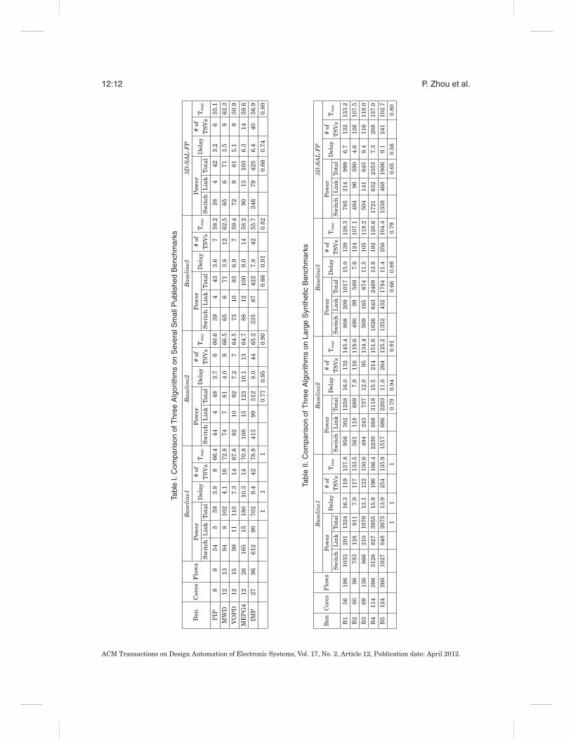
We then applied these four algorithms to design 3D application-specific NoC topolo-gies. We compared these algorithms to a set of existing published benchmarks andseveral large synthetic 3D benchmarks. Since large standard benchmarks are notavailable, we use the method proposed in Yan and Lin [2008b] to build large, syn-thetic 3D benchmarks, which can be viewed as the “many-core” version of the smallpublished ones. This method is based on the NoC-centric bandwidth version of Rent’srule proposed by Greenfield et al. [2007]. For the small published benchmarks, two3D tiers are used, where each tier contains one layer of devices and multiple layers ofinterconnect. For all of the large synthetic benchmarks, four 3D tiers are used.
The corresponding results are shown in Tables I and II. For each algorithm, wereport the following: the network power (in mW, including switch power and linkpower), the average network latency (in ns, evaluated by the accurate delay model),the number of TSVs, and the maximum chip temperature (in ◦C). Considering thatSAL is a stochastic approach, we run each algorithm ten times and present data in thetables showing the best results among all the runs. The same strategy is applied tothe experiments in the subsequent sections.
We can observe that using the improved traffic flow routing algorithm, the Base-line2 algorithm outperforms Baseline1, achieving 23% power saving for the publishedbenchmarks, 10% reduction in chip temperature, and better network performance.The corresponding numbers for synthetic benchmarks is 21% in power saving and9% in chip temperature reduction. Furthermore, Baseline3 uses the feedback fromthe floorplanning step to improve upon Baseline2 and shows 34% reduction in thepower dissipation for both published and synthetic benchmarks, about 20% reductionin chip temperature, and 10% reduction in average network latency. Finally, with our
ACM Transactions on Design Automation of Electronic Systems, Vol. 17, No. 2, Article 12, Publication date: April 2012.
12:12 P. Zhou et al.
Tabl
eI.
Com
paris
onof
Thr
eeA
lgor
ithm
son
Sev
eral
Sm
allP
ublis
hed
Ben
chm
arks
Ben
Cor
esF
low
sB
asel
ine1
Bas
elin
e2B
asel
ine3
3D-S
AL
-FP
Pow
erD
elay
#of
Tm
axP
ower
Del
ay#
ofT
max
Pow
erD
elay
#of
Tm
axP
ower
Del
ay#
ofT
max
Sw
itch
Lin
kT
otal
TS
Vs
Sw
itch
Lin
kT
otal
TS
Vs
Sw
itch
Lin
kT
otal
TS
Vs
Sw
itch
Lin
kT
otal
TS
Vs
PIP
88
545
593.
88
66.4
444
483.
76
60.6
394
433.
67
58.2
384
423.
26
55.1
MW
D12
1394
810
24.
110
72.8
747
814.
09
66.5
656
713.
812
62.5
656
713.
59
62.3
VO
PD
1215
9911
110
7.3
1467
.882
1092
7.2
764
.573
1083
6.9
759
.472
981
5.1
950
.9
ME
PG
412
2616
515
180
10.3
1470
.810
815
123
10.1
1364
.788
1210
09.
014
58.2
9013
103
6.3
1459
.6
IMP
2796
612
9070
29.
442
78.8
413
9951
28.
044
65.2
335
8742
27.
842
55.7
346
7942
56.
440
56.9
11
10.
770.
950.
900.
660.
910.
820.
660.
740.
80
Tabl
eII.
Com
paris
onof
Thr
eeA
lgor
ithm
son
Larg
eS
ynth
etic
Ben
chm
arks
Ben
Cor
esF
low
sB
asel
ine1
Bas
elin
e2B
asel
ine3
3D-S
AL
-FP
Pow
erD
elay
#of
Tm
axP
ower
Del
ay#
ofT
max
Pow
erD
elay
#of
Tm
axP
ower
Del
ay#
ofT
max
Sw
itch
Lin
kT
otal
TS
Vs
Sw
itch
Lin
kT
otal
TS
Vs
Sw
itch
Lin
kT
otal
TS
Vs
Sw
itch
Lin
kT
otal
TS
Vs
B1
5619
610
3329
113
2416
.311
915
7.8
956
302
1258
16.0
132
145.
480
820
910
1715
.013
912
8.3
785
214
999
6.7
132
133.
2
B2
8096
783
128
911
7.9
117
133.
556
111
868
97.
911
611
9.6
490
9958
97.
612
410
7.1
494
9659
04.
612
610
7.5
B3
6913
686
621
010
7613
.112
215
0.6
494
243
737
12.0
9513
4.4
509
165
674
11.5
105
118.
250
414
164
59.
411
611
8.0
B4
114
396
3128
827
3955
15.9
196
166.
422
3088
831
1815
.521
415
1.6
1826
643
2469
13.9
192
128.
617
2163
223
537.
320
813
7.0
B5
124
266
1827
848
2675
13.9
254
135.
915
1768
622
0311
.826
412
5.2
1352
432
1784
11.4
256
104.
413
3846
818
069.
124
110
2.7
11
10.
790.
940.
910.
660.
890.
790.
650.
560.
80
ACM Transactions on Design Automation of Electronic Systems, Vol. 17, No. 2, Article 12, Publication date: April 2012.

Optimized 3D Network-on-Chip Design Using Simulated Allocation 12:13
more accurate delay model, 3D-SAL-FP improves upon Baseline3 with 26% reductionin average network latency for published benchmarks and 44% for the syntheticbenchmarks. Since the objective function for these algorithms is a linear combinationof several metrics, the use of different sets of weighting factors can result in differentPareto-optimal solutions. For a fair comparison, we have used identical weightingfactors for all four algorithms discussed. In the solutions shown here, 3D-SAL-FPperforms significantly better than Baseline3 in reducing the delay and is slightlybetter, on average, (and sometimes worse on specific examples) in terms of power andtemperature. By altering the weights, other trade-off points may be identified.
6.3. 3D-SAL-FP Based on Multipath Routing
In Section 6.2, our 3D-SAL-FP algorithm is based on single-path routing, which meansthat each commodity (traffic flow in the given core graph) is nonbifurcated, and wechoose one single path in the routing graph for one commodity. In this section, weextend 3D-SAL-FP to work with multipath routing, where each commodity can be splitinto several subflows, and each subflow can be routed independently in the routinggraph.
Let L be the capacity of each subflow, then a commodity with traffic demand di canbe split into �di/L� subflows. Here we use the capacity L to control the granularity ofthe subflow, so that the size of the MCF problem in multipath routing can be controlled.In our experiments, L is set individually for each benchmark because the values of thetraffic demand di vary greatly from benchmark to benchmark. After splitting the com-modities in the core graph, we treat each of the resulting subflows as a single routingunit and select one minimum cost path to route it. Since the subflows constituting thesame commodity can be routed on different paths on the routing graph, we refer to thenew routing problem supporting subflows as multipath routing. In fact, the costs forthe switches and links in the routing graph are state-dependent: when the subflowsare routed one after another, it is highly possible for the subflows of one commodity tobe routed on different paths.
Figure 2 presents the comparison results of single-path and multipath routings.The results are normalized to the single-path case. Considering that multipath rout-ing can reduce the peak link bandwidth needs and therefore lower network operatingfrequency [Murali et al. 2006], we evaluate the network power consumption using theoptimized frequency number corresponding to the peak link bandwidth in the NoCsynthesis solution. Given the peak link bandwidth, we can obtain the optimized NoCfrequency as optimized frequency = peak link bandwidth/link width.
From Figure 2, we can see that, on average, multipath routing can obtain 35% powersavings compared to single-path routing. The overhead in runtime for multipath rout-ing is more than 3 times that of most of the benchmarks. This is because 1) it takeslonger time for SAL to find a full allocation solution in multipath routing, and 2) SALneeds to explore an expanded solution space for the multipath case. However, thisoverhead is related to the increased search space and will affect any other algorithm(e.g., SA) that solves this problem formulation.
6.4. Comparison of SAL and Simulated Annealing
In this section, we compare the performance of our single-path-based SAL algorithmwith another widely used stochastic approach, Simulated Annealing (SA), by replacingSAL with SA in the 3D-SAL-FP implementation. We implement two kinds of SA movesin our work.
(1) Consider that in Algorithm 1, the SAL approach applies two basic moves,allocation(x) and disconnect(x). In order to perform a fair comparison, we
ACM Transactions on Design Automation of Electronic Systems, Vol. 17, No. 2, Article 12, Publication date: April 2012.

12:14 P. Zhou et al.
Fig. 2. Comparisons of single-path and multipath routing schemes.
integrate these two basic moves into the SA engine: in SA, given one fullallocation state x, a move to a neighbor full allocation state neighbor(x) is im-plemented as a series of single-flow moves (allocation(x) and disconnect(x)), asintroduced in Section 5.1. We refer to this SA implementation as Single-flow SA.
(2) Given one full allocation state x, a move to a neighbor full allocation state neigh-bor(x) can be obtained in one of two ways.— Disable one of the used switches and reroute all the traffic flows passing
through that switch.— Disable one of the used links and reroute all the traffic flows passing through
that link.For this SA implementation, several flows may be rerouted in one single move,so we refer to it as Multi-flow SA.
The performance and runtime of the SA algorithm is affected by several parameters,such as the initial and end temperatures Ti and Te, the inner loop number Ninner at eachtemperature, and the temperature reduction parameter τ . We investigate the impactof runtime on SA’s performance with one randomly selected benchmark IMP. Figure 3shows the simulation results when Single-flow SA is applied. We use the following costfunction to evaluate the final 3D NoC solutions.
cost = w1∗chip area + w2∗network power + w3∗network latency + w4∗TSV count, (7)
ACM Transactions on Design Automation of Electronic Systems, Vol. 17, No. 2, Article 12, Publication date: April 2012.

Optimized 3D Network-on-Chip Design Using Simulated Allocation 12:15
Fig. 3. The impact of runtime on the performance of SA for benchmark IMP.
where the default weights are w1 = 1, w2 = 10, w3 = 5, and w4 = 3. We normalize allthe costs to the baseline case with a runtime of 120 seconds. We tune the parametersfor an appropriate runtime/quality trade-off from SA. For example, for benchmarkIMP, Figure 3 shows that as we increase the runtime of SA from 120 seconds to 2,398seconds, the improvement to the objective function shows diminishing returns: theimprovement is very small, but the increase in the runtime is about 20 times. Wefactor this into our experiments, and the runtime of SA for the benchmarks rangesfrom several minutes to several hours.
Figure 4 presents the results of SAL and two SA implementations on both the pub-lished and synthetic benchmarks. We use the cost function shown in Equation (7),where all results are normalized to the SAL case. Figure 4 shows that in terms ofthe quality of the solutions, SAL performs approximately as well as SA, but that theexecution times are much smaller than those of SA. For example, for the large bench-mark B5 with 124 cores and 266 flows, the cost reported by SAL is about 3% less thanthat of Single-flow SA, while the speedup is about 18 times. Compared to Multi-flowSA, Single-flow SA has longer execution time for most of the benchmarks because itneeds more moves to find a neighbor full allocation state, but it can find slightly bettersolutions in most cases.
6.5. Exploration of TSV Count
Next, we explore the trade-offs associated with using more or fewer TSVs in the design.In 3D circuits, more TSVs imply more vertical interconnects, which mean that thelatency can be reduced in the resulting NoC topology. However, the correspondingoverhead includes increased design area and excessive utilization of a valuable verticalresource (note that TSVs are also required for routing supply nets, clock nets, thermalvias, etc.). In this section, we explore the trade-off between TSV count and networklatency. The single-path-based 3D-SAL-FP algorithm is applied for this experiment.
Figure 5 shows the trade-off curve when we gradually increase the weight of TSVw4 (Equation (2)) from 1 to 18. As we can see from this figure, the number of TSVs canbe largely optimized when we increase w4 from 1 to 6, and the increase of the networklatency is less than 2%. After that point, the TSV count gradually levels off, and thenetwork latency increases much faster. The minor nonmonotonicities in this figure canbe attributed to the nature of the stochastic approach.
6.6. Delay and Power Reduction Potential in 3D NoCs
In this section, we further investigate the impact of 3D integration on the NoC ar-chitecture design. The benchmark B3 (with 69 cores and 136 flows) was selected, and
ACM Transactions on Design Automation of Electronic Systems, Vol. 17, No. 2, Article 12, Publication date: April 2012.

12:16 P. Zhou et al.
Fig. 4. Comparisons with SA.
our 3D-SAL-FP algorithm was applied to synthesize this benchmark with differentnumbers of 3D tiers, from 1 to 4. The 1-tier case is the design that uses conventional2D technology. The results are shown in Table III. For each case, we list the followingresults: the design footprint, the network power, the maximum path length, themaximum total link delay, the maximum network latency, the average networklatency, the total number of TSVs, the maximum chip temperature, and the CPU time.
Our results show a clear trade-off when implementing NoC architecture using 3Dcircuits: as the number of 3D tiers increases, the footprint size continues to decrease,together with the maximum length of the path to route the packets. The reduced pathlength further brings down the maximum link delay and the total link power at thecost of an increased number of TSVs and higher chip temperature. In addition, wecan observe that although 3D circuits have the potential to reduce the link delay andpower, the improvement flattens out as the number of 3D tiers goes beyond a certainpoint. For example, as shown in Table III, the network latency does not decrease muchas we go from three layers to four.
7. CONCLUSION
We have proposed an efficient algorithm 3D-SAL-FP to synthesize application-specific3D NoC architectures. Our algorithm utilizes a stochastic approach called simulated
ACM Transactions on Design Automation of Electronic Systems, Vol. 17, No. 2, Article 12, Publication date: April 2012.

Optimized 3D Network-on-Chip Design Using Simulated Allocation 12:17
Fig. 5. The trade-off between number of TSVs and average network latency for benchmark B1.
Table III. Comparison of the Impact of Different Numbers of 3D Tiers on NoC Architecture Designfor Benchmark B3
LayersFootprint
Network Power Max Path Max Link Max Network Avg Network # of Tmax Time(mm2)
Switch Link Total Length Delay Latency Latency TSVs (◦C) (s)(mW) (mW) (mW) (mm) (ns) (ns) (ns)
1 216.8 510.5 288.4 798.9 22.1 6.45 14.40 12.42 0 43.8 85.8
2 110.3 505.8 189.2 695.0 17.0 4.95 12.28 9.56 86 63.7 83.9
3 72.0 510.7 164.8 675.5 11.9 3.50 11.51 9.49 94 96.2 87.3
4 56.1 504.8 141.0 645.8 9.2 2.68 11.32 9.44 116 118.0 87.4
allocation (SAL) to reduce the dependency of NoC design results on flow ordering. Wealso use an accurate delay model for switches in NoCs, which considers the queueingdelay and network contention. Finally, our algorithm performs the floorplanning ofcores/switches and NoC topology synthesis in an integrated iterative loop, attemptingto find the optimal solution for the problem of application-specific NoC design.
Experimental results on a set of benchmarks show that our algorithm can producegreatly improved solutions, compared to the baseline algorithm with fixed-order flow-routing, simple delay model and without feedback from floorplanning step, reflectingprior work. In comparison with SA, we show that SAL can find approximately thesame quality solutions but with better computational efficiency.
We have also investigated several degrees of freedom in this space. First, ourcomparative study between single-path and multipath routing schemes in the SALframework shows that multipath routing can achieve large power savings withslightly larger computation times. Second, when we study the impact of TSV count onthe network performance in 3D NoCs, we find that there is a “sweet spot” where theTSV count is effectively controlled without much penalty on the network performance.Third, we investigate the benefits that 3D circuits can bring to the NoC architecturedesign and show that link power and delay can be largely improved when moving to3D implementation, at the cost of TSV and chip temperature.
ACKNOWLEDGMENTS
The authors would like to thank Professor Yuan Xie at Pennsylvania State University for providing the 3Dfloorplanner.
ACM Transactions on Design Automation of Electronic Systems, Vol. 17, No. 2, Article 12, Publication date: April 2012.

12:18 P. Zhou et al.
REFERENCESADDO-QUAYE, C. 2005. Thermal-aware mapping and placement for 3-D NoC designs. In Proceedings of the
IEEE International System-on-Chip Conference. 25–28.AHONEN, T., BIN, H., AND NURMI, J. 2004. Topology optimization for application-specific networks-on-chip.
In Proceedings of the International Workshop on System Level Interconnect Prediction. 53–60.BANERJEE, K., SOURI, S. J., KAPUR, P., AND SARASWAT, K. C. 2001. 3-D ICs: A novel chip design for
improving deep-submicrometer interconnect performance and systems. Proc. IEEE 89, 5.BENINI, L. AND MICHELI, G. D. 2002. Networks on chips: A new SoC paradigm. Computer 35, 1, 70–78.DALLY, W. J. AND TOWLES, B. 2001. Route packets, not wires: On-chip inteconnection networks. In Pro-
ceedings of the ACM/IEEE Design Automation Conference. 684–689.DAVIS, W. R., WILSON, J., MICK, S., XU, J., HUA, H., MINCO, C., SULE, A. M., STEER, M., AND FRANZON,
P. D. 2005. Demystifying 3D ICs: The pros and cons of going vertical. IEEE Des. Test Comput. 22, 6,498–510.
FEERO, B. AND PANDE, P. P. 2007. Performance evaluation for three-dimensional networks-on-chip. InProceedings of the IEEE Annual Symposium on VLSI. 305–310.
GREENFIELD, D., BANERJEE, A., LEE, J.-G., AND MOORE, S. 2007. Implications of Rent’s rule for NoCdesign and its fault-tolerance. In Proceedings of the ACM/IEEE International Symposium on Networks-on-Chip. 283–294.
HANSSON, A., GOOSSENS, K., AND RADULESCU, A. 2005. A unified approach to constrained mapping androuting on network-on-chip architectures. In Proceedings of the International Conference on Hardware-Software Codesign and System Synthesis. 75–80.
HU, Y., CHEN, H., ZHU, Y., CHIEN, A. A., AND CHENG, C.-K. 2005. Physical synthesis of energy-efficientnetworks-on-chip through topology exploration and wire style optimizations. In Proceedings of theInternational Conference on Computer Design. 111–118.
HU, Y., ZHU, Y., CHEN, H., GRAHAM, R., AND CHENG, C.-K. 2006. Communication latency aware low powerNoC synthesis. In Proceedings of the ACM/IEEE Design Automation Conference. 574–579.
HUNG, W.-L., LINK, G. M., XIE, Y., VIJAYKRISHNAN, N., AND IRWIN, M. J. 2006. Interconnect andthermal-aware floorplanning for 3D microprocessors. In Proceedings of the International Symposiumon Quality Electronic Design. 98–104.
KAHNG, A., SAMADI, K., LI, B., AND PEH, L.-S. 2009. ORION 2.0: A fast and accurate NoC power and areamodel for early-stage design space exploration. In Proceedings of the Design, Automation and Test inEurope.
KIM, J., NICOPOULOS, C., PARK, D., DAS, R., XIE, Y., NARAYANAN, V., YONSIF, M. S., AND DAS,C. R. 2007. A novel dimensionally-decomposed router for on-chip communication in 3D architectures.In Proceedings of the International Symposium on Computer Architecture. 138–149.
LI, F., NICOPOULOS, C., RICHARDSON, T., XIE, Y., NARAYANAN, V., AND KANDEMIR, M. 2006. Design andmanagement of 3D chip multiprocessors using network-in-memory. In Proceedings of the InternationalSymposium on Computer Architecture. 130–141.
LIM, S. K. 2005. Physical design for 3D system on package. IEEE Des. Test Comput. 22, 6, 532–539.LITTLE, J. D. C. 1961. A proof for the queuing formula: L = λW. Oper. Res. 9, 3, 383–387.LOI, I., ANGIOLINI, F., AND BENINI, L. 2007. Supporting vertical links for 3D networks-on-chip: Toward an
automated design and analysis flow. In Proceedings of the International Conference on Nano-Networks.1–5.
MARK, D. S., KARPOVSKY, M., AND ZAKREVSKI, L. 2003. Application of network calculus to general topolo-gies using turn-prohibition. IEEE/ACM Trans. Netw. 11, 3, 411–421.
MATSUTANI, H., KOIBUCHI, M., AND AMANO, H. 2007. Tightly-coupled multi-layer topologies for 3-D NoCs.In Proceedings of the International Conference on Parallel Processing. 75–75.
MORROW, P., BLACK, B., KOBRINSKY, M. J., MUTHUKUMAR, S., NELSON, D., PARK, C.-H., AND WEBB,C. 2007. Design and fabrication of 3D microprocessors. In Proceedings of the Materials Research SocietySymposium.
MURALI, S., MELONI, P., ANGIOLINI, F., ATIENZA, D., CARTA, S., BENINI, L., DE MICHELI, G., ANDRAFF, L. 2006. Designing application-specific networks on chips with floorplan information. In Proceed-ings of the IEEE/ACM International Conference on Computer-Aided Design. 355–362.
MURALI, S., SEICULESCU, C., BENINI, L., AND MICHELI, G. D. 2009. Synthesis of networks on chips for3D systems on chips. In Proceedings of the Asia-South Pacific Design Automation Conference. 242–247.
OGRAS, U. Y. AND MARCULESCU, R. 2007. Analytical router modeling for networks-on-chip performanceanalysis. In Proceedings of the Design, Automation and Test in Europe. 1096–1101.
ACM Transactions on Design Automation of Electronic Systems, Vol. 17, No. 2, Article 12, Publication date: April 2012.

Optimized 3D Network-on-Chip Design Using Simulated Allocation 12:19
PAVLIDIS, V. F. AND FRIEDMAN, E. G. 2007. 3-D topologies for networks-on-chip. IEEE Trans. VLSISyst. 15, 10, 1081–1090.
PIORO, M. AND GAJOWNICZEK, P. 1997. Solving multi commodity integral flow problems by simulatedallocation. Telecomm. Syst. 7, 1–3, 17–28.
PIORO, M. AND MEDHI, D. 2004. Routing, Flow, and Capacity Design in Communication and ComputerNetworks. Morgan Kaufmann Publishers Inc., San Francisco, CA.
SEICULESCU, C., MURALI, S., BENINI, L., AND MICHELI, G. D. 2009. SunFloor 3D: A tool for networks onchip topology synthesis for 3D systems on chip. In Proceedings of the Design, Automation and Test inEurope. 9–14.
SRINIVASAN, K., CHATHA, K. S., AND KONJEVOD, G. 2005. An automated technique for topology and routegeneration of application specific on-chip interconnection networks. In Proceedings of the IEEE/ACMInternational Conference on Computer-Aided Design. 231–237.
WANG, H., ZHU, X., PEH, L.-S., AND MALIK, S. 2002. Orion: A power-performance simulator for intercon-nection networks. In Proceedings of the Annual IEEE/ACM International Symposium on Microarchitec-ture. 294–305.
XUE, L., LIU, C. C., KIM, H.-S., KIM, S. K., AND TIWARI, S. 2003. Three-dimensional integration: Tech-nology, use, and issues for mixed-signal applications. IEEE Trans. Electron Devices 50, 3, 601–609.
YAN, S. AND LIN, B. 2008a. Application-specific network-on-chip architecture synthesis based on setpartitions and Steiner trees. In Proceedings of the Asia-South Pacific Design Automation Conference.277–282.
YAN, S. AND LIN, B. 2008b. Design of application-specific 3D networks-on-chip architectures. In Proceedingsof the International Conference on Computer Design. 142–149.
ZHOU, P., YUH, P.-H., AND SAPATNEKAR, S. 2010. Application-specific 3D network-on-chip design usingsimulated allocation. In Proceedings of the Asia-South Pacific Design Automation Conference. 517–522.
Received March 2011; revised June 2011, September 2011; accepted November 2011
ACM Transactions on Design Automation of Electronic Systems, Vol. 17, No. 2, Article 12, Publication date: April 2012.


![Optimized combinatorial clustering for stochastic processes · budget allocation and Bayesian decision-theoretic methods used an average case analysis [5,8,33]. All three procedures](https://img.pdfslide.net/doc/110x75/5f41984f0c68ba7f5c6e576a/optimized-combinatorial-clustering-for-stochastic-processes-budget-allocation-and.jpg)


![An Optimized Flow Allocation in Vehicular Cloud Optimized Flow...More sophisticated applications, such as Vehicular Cloud Computing (VCC) could be operable in tandem [4]. Cloud computing](https://img.pdfslide.net/doc/110x75/5abd80587f8b9aa3088bb341/an-optimized-flow-allocation-in-vehicular-optimized-flowmore-sophisticated-applications.jpg)


![Optimized Base-Station Cache Allocation for Cloud …arXiv:1804.10730v1 [cs.IT] 28 Apr 2018 1 Optimized Base-Station Cache Allocation for Cloud Radio Access Network with Multicast](https://img.pdfslide.net/doc/110x75/5e8cc95f236bf92dee25ab6d/optimized-base-station-cache-allocation-for-cloud-arxiv180410730v1-csit-28.jpg)


![Computation Offloading and Resource Allocation in … · was optimized for each task of each UE. In [10] and [19], game theory was utilized to optimized offloading decisions in](https://img.pdfslide.net/doc/110x75/5b900f2309d3f2c7748d4ccc/computation-offloading-and-resource-allocation-in-was-optimized-for-each-task.jpg)