Embed Size (px)
Citation preview
Optimized Approach for Determination of the SolidTemperature in a Steam Turbine inWarm-Keeping-OperationDennis Toebben1*, Piotr Luczynski1, Manfred Wirsum1, Wolfgang Mohr2, Klaus Helbig3
SYM
POSI
A
ON ROTATING MACHIN
ERY
ISROMAC 2017
InternationalSymposium on
Transport Phenomenaand
Dynamics of RotatingMachinery
Maui, Hawaii
December 16-21, 2017
Abstract�e determination of the temperature distribution in the thick-walled components in steam turbinesis increasing in relevance. Due to the growing share of volatile renewable power generation, powerplants with a high �exibility and a high integral e�ciency are required. �e current operationalconditions lead to high thermal stresses inside the heavy components and thus to a reduced lifetime.To improve the ability for a fast start-up, the steam turbine can be kept warm during a longer periodof stand still. �erefore, information about the metal temperature inside the rotor and the casing arecrucial. However, the temperature distribution of the inner casing and especially the rotor cannotbe measured without high additional e�ort. �us, a calculation model with su�cient accuracyand also manageable calculation e�ort is required. In the present work, a hybrid – numerical FEMand analytical – approach has been developed to calculate the solid body temperatures of a steamturbine in warm-keeping operation in a most e�cient way. �e presented model provides accuracyof nearly 90% compared with Conjugate-Heat-Transfer simulations with a simultaneously reducedcalculation e�ort by a factor of more than 600.KeywordsSteam Turbine Modeling — Flexibilization — Warm-keeping1Institute for Power Plant Technology, Steam and Gas Turbines, RWTH Aachen University, 52062 Aachen, Germany2General Electric (Switzerland) GmbH, Brown Boveri Str. 7, 5401 Baden, Switzerland3General Electric Power AG, Boveristraße 22, 68309 Mannheim, Germany*Corresponding author: [email protected]
INTRODUCTIONToday, power plants using steam turbines are responsiblefor more than 50% of the worldwide power generation [1].Most of these power plants have an age of thirty years andmore [2]. Within the last decade, renewable energies arecontinuously gaining in�uence in the energy supply sector.�ese renewables lead to a �uctuating power feed-in into thegrid which needs to be regulated by the conventional genera-tion system. Most of the installed capacities of steam turbinepower plants are designed for basic load with a limited abilityfor high load ramps and fast start-ups. Consequently, theexisting power plants need to be revised and improved toincrease the operational �exibility.
Further decreasing operating hours of the conventionalpower plants and thus an increasing cost pressure in theenergy sector are another result of the growing share ofrenewable energies. For the decision whether a power plantgoes on stream, the importance of the start-up costs is stillincreasing. �e base load e�ciency is no longer critical, butrather the integral e�ciency including the start-up and shut-down procedure as well as base, part and minimum loadoperation.
One option to improve the �exibility and the integrale�ciency is to keep the steam turbine in a warm conditionbetween a shut-down and the next start-up. �e requiredcompensation of the losses can be achieved by the use ofheat blankets [3], gland steam [4] or even by hot air, which
is, for example, passed through the steam turbine [5]. �elast approach is the basis for the present investigations.
For an e�cient, fast and lifetime conserving start-up theknowledge of the temperature distribution within the thickwalled components of the steam turbine is crucial. Especiallythe temperature of the rotor is a determining factor which isnot measured in commercially operated steam turbines. �edetermination of the rotor temperature distribution can onlyachieved by large technical and �nancial e�orts [6], [7], [8].�us, a retro�t of such ameasurement system is currently notappropriate for commercial use. Hence, a di�erent solutionfor the rotor temperature prediction needs to be found.
Considerable improvements of the computing power andnumerical simulation tools enable a relatively detailed in-vestigation of the heat transfer and the �ow phenomenain steam turbines [9]. However, detailed �uid-dynamic cal-culations can only be conducted for a limited number ofnumerical nodes so far. �is leads to either smaller geome-tries or to coarser numerical meshes and consequently toa reduced accuracy. A highly accurate coupled �uid andsolid 3D-simulation of a whole multistage steam turbine canonly be conducted with prohibitive expense. �erefore, asimpli�ed calculation model is required.
Several analytical approaches for calculating the heattransfer within a steam turbine are known from literature.Brilliant et al. [10] developed a separate calculation modelfor both an impulse and a reaction steam turbine, using di�er-
Optimized Approach for Determination of the Solid Temperature in a Steam Turbine in Warm-Keeping-Operation — 2/10
ent Nusselt-correlations from literature for various surfaces.�ese Nusselt-correlations are used to calculate the convec-tive heat transfer coe�cient (HTC) between steam and thesolid structure to serve as an input for further numericalFEM simulations. �ey calculate di�erent discrete operatingpoints from start-up till base load. Particularly in the start-upphase the models are not able to reproduce the test data inan appropriate way.
Rzadkowski et al. [11] analyse the transient thermalbehavior of a steam turbine during its start-up in discrete timesteps. �ey use Reynolds-averaged Navier-Stokes equations(RANS) in a CFD simulation for calculating the heat transfercoe�cients. Furthermore, Nusselt-correlation taken fromliterature were used to calculate the heat transfer withinthe labyrinth seals and due to condensation within the �owchannel. �ese HTCs were used to couple the �ow and thesolid body in a FEM model.
A further approach was developed by Pusch et al. [12].�e aim of the investigation was to simulate the start-up pro-cedure of an intermediate pressure steam turbine to analyzelow-cycle-fatique. �erefore, a numerical FEM model wasdeveloped including the rotor and the inner casing. Variousanalytical heat transfer correlations were used to calculatethe heat transfer. �e absorption of heat by the blades andvanes is calculated by a modi�ed correlation which convertsthe HTC at the blade surfaces (Nusselt-approach developedby Traupel et al. [13]) to an equivalent HTC at the endwall.�us, only the blade and vane root needs to be integratedinto the model.
Moroz et al. [14] conducted a transient thermo-structuralanalysis of a combined high pressure / intermediate pressuresteam turbine during a start-up. For these investigations aFEM model was developed, which includes the rotor andthe inner casing of the steam turbine. �e FEM model wasseparated into several heat transfer zones in which analyti-cal heat transfer correlations from literature were used. Inaddition to the convective heat transfer, the model is able tocalculate condensation within the individual zones. Basedon these analytical equations, the temperature distributionof the rotor was analyzed. �ese calculations were used todetermine the rotor displacement in several discrete timesteps during the start-up phase.
Wang et al. [15] investigate the impact of the steamtemperature �uctuation during steady-state operation onthe temperature �eld within the rotor. �e heat transferbetween the steam and the rotor is calculated by analyticalequations concerning the rotor surface, the seal structure andthe blade groove. �e heat transfer coe�cients serve as aninput parameter for a FEM rotor model. It is assumed that allheat �uxes received by the blades are conducted into the rotorthrough the contact between blade root and blade groove.Similar to the approach of Pusch et al. [12], the blades aresimpli�ed as the blade roots and integrated into the model. Inaddition, an analytical approach for determining the contactresistance at the blade-rotor-connection depending on therotational speed is included.
Born et al. [16] developed a numerical model of an in-termediate pressure steam turbine for the investigation ofsteady state operation and natural cooling e�ects. �e modelincludes the inner and outer casing and the labyrinth seals.�e rotor is not modeled. �e authors used several analyticalheat transfer correlations based on approaches from liter-ature for determining the heat transfer by forced and freeconvection, radiation and conduction.
All these investigations were made with steam as op-erational �uid. �e present paper deals with an optimizedapproach for the determination of the solid temperature ina steam turbine during warm-keeping-operation with hotair. Hence, the previous calculation approaches are inap-propriate. A simpli�ed Hybrid-FEM model (HFEM) has beendeveloped, which uses analytical heat transfer correlationscoupled with a FEM model for time-optimized calculationof the solid body temperature distribution. �e model con-sists out of a repetitive stage including inner casing, rotor,vane, blade and shrouds. In comparison to the approachesknown from literature, the present model uses detailed nu-merical Conjugate-Heat-Transfer (CHT) investigations [9] todevelop suitable heat transfer correlations for the most rele-vant surfaces concerning the heat transfer. �e FEM modelwas developed on basis of the CHT model grid. �e �uid gridwas removed and the solid grid was coarsened to optimizethe calculation time. �us, on the one hand heat transfer andtemperature analysis can be made with minimized calcula-tion e�ort and on the other hand high resolution.
In the �rst part of the present paper, the model setup andthe boundary conditions of the warm-keeping operation withair are introduced. Subsequently, the analytical calculationmodels for convection and radiation are presented. Finally, acomparison between the results of the numerical CHT modeland the Hybrid-FEM model is conducted, which shows theadvantages of the simpli�ed model.
NOMENCLATURESymbolsA Areaa,b1,b2 Empirical parameterF View factorh Heat transfer coe�cientl Characteristic lengthm mass �ow raten rotational speedn Number of operating pointsNu Nusselt-numberp PressurePr Prandtl numberQ Heat �uxq Area related heat �uxr Radiusr1 / r2 Inner / outer �ow channel radius
Optimized Approach for Determination of the Solid Temperature in a Steam Turbine in Warm-Keeping-Operation — 3/10
Re Reynolds-numberT TemperatureT Surface average temperature¯T Mass �ow average temperatureu Rotational velocity at blade outletv Velocity
Greekε Emissivityρ Densityν Kinematic viscosityλ Conductivityσ Stefan-Boltzmann constant
Subscripts0 Maximum valueax Axialcorr Correlatione� E�ectivei Surfacen Plane (stage interface)t Totalu Circumferential
AbbreviationsCFD Computational �uid dynamicsCHT Conjugate-Heat-TransferFEM Finite element methodHFEM Hybrid-FEM modelHTC Heat transfer coe�cientQ1 / Q2 �adrant 1 / �adrant 2rRMSE Relative root mean square error
1. HYBRID-FEM MODEL�e Hybrid-FEM model uses hybrid calculation approaches:�e heat transfer within the solid body is calculated by theuse of a Finite Element approach while the heat exchangeby forced convection, radiation or contact heat transfer iscalculated by a semi empirical approach based on detailedConjugate-Heat-Transfer (CHT) simulations.
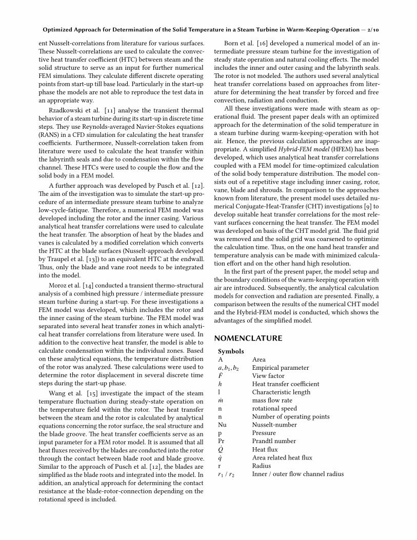
Figure 1 provides detailed information about the modelsetup of the Hybrid-FEM model. In the case of fast and fre-quent start-ups and high load ramps, the impact on the life-time is crucial. �erefore, information about the temperatureand stress distribution of the turbine in such o�-design opera-tions are important. �e Hybrid-FEMmodel can be applied toprovide these information. A numerical �uid and solid meshfor one repetitive stage is generated from the basis turbinedesign. With this mesh, a CHT model is developed which isused for calculating a characteristic map regarding the op-erating range of interest (e.g. start-up phase, warm-keepingor pre-warming). To secure a appropriate resolution of thethermal boundary layer, the near wall heat transfer is mod-eled based on the Low-Reynolds-Number method (kω-SSTturbulence model), which resolves the details of the bound-ary layer pro�le by using very small mesh length scales in
the direction normal to the wall. �e �uid boundary layery+ is smaller then 1.0 to secure a �ne mesh resolution. Fortransferring these calculation results into the Hybrid-FEMmodel, modi�ed Nusselt-Correlations are used to �t the char-acteristic HTC map. In contrast to the requirements of theCHT model, a coarse solid body mesh is su�cient for theHybrid-FEM model’s purposes. Hence, the �uid mesh is re-moved from the initial mesh and the solid mesh is coarsened.�is repetitive stage mesh can be multiplied to any needednumber of turbine stages (neglecting the �ow channel ex-pansion). In a �nal step the adapted analytical heat transfercorrelations are integrated into the model. �e result is theHybrid-FEMmodel which is able to calculate the temperatureand stress distribution within large scale turbine geometrieswith improved accuracy. �is is reasoned by individuallymodi�ed heat transfer equations, which provide a reduced aswell as at least manageable calculation e�ort for simulatinga whole multistage steam turbine.
In comparison to other approaches, the Hybrid-FEMmodel uses adapted instead of general heat transfer correla-tions for a speci�c turbine geometry and speci�c operationconditions. In the next step of the ongoing investigation theHybrid-FEM model will be validated against experimentaldata. Due to the strong basis of the CHT simulations just afew regular operation measurements are su�cient to validatethe model.
�e presented Hybrid-FEM model is used to calculate awarm-keeping operation of a steam turbine. In general, thewarm-keeping process is designed to increase the �exibilityand reduce the lifetime consumption. �e warm-keepingprocedure is characterized by a hot gas (e.g. air) which ispassed through the turbine to compensate the heat losses
Figure 1. Process chart - Hybrid-FEM model
Optimized Approach for Determination of the Solid Temperature in a Steam Turbine in Warm-Keeping-Operation — 4/10
primarily to the ambient and the lubricant oil system. �esteam turbine rotates during the warm-keeping process. Be-sides the conventional rotation direction, it is possible torotate the steam turbine rotor in reverse direction to increasethe warm-keeping e�ciency [5]. �e operating case withconventional rotation direction is called quadrant 1 (Q1) andthe other one quadrant 2 (Q2).
�e heat transfer and �ow phenomena in warm-keepingoperation have already been investigated [9]. For this analy-sis a numerical 3D single stage CHT-model was used charac-terized by the following assumptions:
• Steady-state CHT-simulation
• Single blade passage (approx. 2.5◦) with periodic bound-aries in circumferential direction
• Frozen rotor-stator interface
• Fully turbulent ideal gas with constant �uid properties
• No heat radiation
• Low Reynolds kω-SST turbulence model
• Constant material properties for the solid state
• Fluid boundary layer: y+ ≤ 1.0
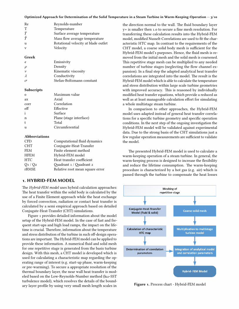
Toebben et al. [9] �gured out that in warm-keeping op-eration most of the heat is transferred by forced convectionfrom the �uid to blades and vanes. �ese kind of �ns conductthe heat through the blade-rotor respectively vane-casingconnection to the main turbine components. �erefore, thecontact heat resistance between these surfaces is importantfor calculating the overall heat transfer and the tempera-ture distribution within rotor and casing. Besides convection,heat radiation within the �ow channel and between the innerand outer casing occurs. �e in�uence of the heat radiationdepends on the surface temperatures. In contrast to theinvestigations of the �ow phenomena and the convectiveheat transfer in which the radiative heat transfer could beneglected due to similar suface temperatures (steady-stateoperation), the relevance of radiation increases for transientoperations. �us, the three heat transfer phenomena convec-tion, radiation and contact heat transfer need to be integratedinto the Hybrid-FEM model by using analytical calculationapproaches (Fig.2).
�e coarsened solid mesh of the single stage Hybrid-FEMmodel has only 5.1 · 104 nodes. In comparison to the solidmesh of the CHTmodel the reduction factor is 63. �e qualityand accuracy of the coarsened mesh was proven in a meshstudy. �e reduction of the number of nodes is permi�edbecause there is no �uid mesh and thus, the interpolationbetween �uid and solid mesh is no longer crucial. �e �uidmesh usually has a much higher number of nodes than thesolid mesh to ensure a high resolution of the �ow phenomenaand the thermal boundary layer. �e numerical solver needsto interpolate between the �uid and the solid mesh. Hence,the resolution of the solid mesh is also crucial for the accuracy
of the heat transfer calculation. Once the �uid mesh is nolonger needed, the solid mesh can be coarsened signi�cantly.�e total mesh reduction factor of the �nal Hybrid-FEMmeshcompared to the �uid (3.6 · 106 nodes) and solid (3.2 · 106
nodes) CHT mesh is 133. With this mesh resolution it ispossible to simulate a whole steam turbine with acceptablecomputational e�ort.
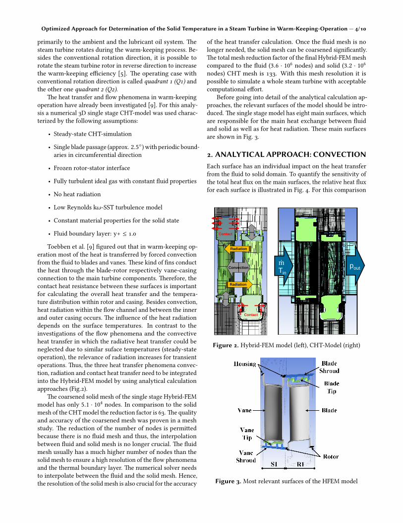
Before going into detail of the analytical calculation ap-proaches, the relevant surfaces of the model should be intro-duced. �e single stage model has eight main surfaces, whichare responsible for the main heat exchange between �uidand solid as well as for heat radiation. �ese main surfacesare shown in Fig. 3.
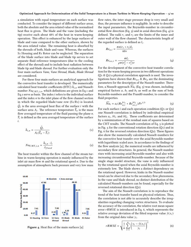
2. ANALYTICAL APPROACH: CONVECTIONEach surface has an individual impact on the heat transferfrom the �uid to solid domain. To quantify the sensitivity ofthe total heat �ux on the main surfaces, the relative heat �uxfor each surface is illustrated in Fig. 4. For this comparison
Convection
Contact
Contact
Radiation
Radiation
Tin
pout
Figure 2. Hybrid-FEM model (le�), CHT-Model (right)
Figure 3. Most relevant surfaces of the HFEM model
Optimized Approach for Determination of the Solid Temperature in a Steam Turbine in Warm-Keeping-Operation — 5/10
a simulation with equal temperature on each surface wasconducted. To consider the impact of di�erent surface areas,both the absolute and the area related value of the normalizedheat �ux is given. �e blade and the vane (including thetip) receive each about 48% of the heat in warm-keepingoperation. �is e�ect is enhanced by the large surfaces ofblade and vane compared to the other surfaces, shown bythe area related value. �e remaining heat is absorbed bythe shrouds of both, blade and vane. Whereas, the surfacesS1 Housing and R1 Rotor can be neglected. �e separationof the blade surface into blade and blade tip serves to setseparate �uid reference temperatures (due to the coolinge�ect of the shroud) and to include heat radiation betweenblade tip and blade shroud. For further evaluation only thefour main surfaces Vane, Vane Shroud, Blade, Blade Shroudare considered.
For these four main surfaces an analytical approach forthe convective heat transfer is developed. �e numericallycalculated heat transfer coe�cients (HTC) hi,n and Nusselt-number NuCHT , i,n , which de�nitions are given in Eq.1 andEq.2 serve as basis. �e index i refers to the individual surfaceand the index n to the inlet plane of the �ow channel sectionin which the regarded blade/vane row (S1/R1) is located.¯Qi is the area averaged heat �ux of the surface i with thesurface area Ai . �e reference temperature ¯Tn is the mass�ow averaged temperature of the �uid passing the plane n.Ti is de�ned as the area averaged temperature of the surfacei.
hi,n =
¯Qi
Ai ( ¯Tn − Ti )(1)
NuCHT , i,n =hi,n · liλ f luid
(2)
�e heat transfer within the �ow channel of the steam tur-bine in warm-keeping operation is mainly in�uenced by theinlet air mass �ow m and the rotational speed n. Due to theassumption of atmospheric back pressure and very low mass
Figure 4. Heat �ux of the main surfaces [9]
�ow rates, the inter stage pressure drop is very small andthus, the pressure in�uence is negligible. In order to describethe input parameters, the Reynolds-number in circumfer-ential �ow direction (Eq. 3) and in axial direction (Eq. 4) isde�ned. �e radii r1 and r2 are the limits of the inner andouter wall of the �ow channel. �e characteristic length ofthe regarded surface is de�ned as li .
Reu, i =πn(r1 + r2)li
60ν (3)
Reax, i =mli
ρπ(r22 − r2
1 )ν(4)
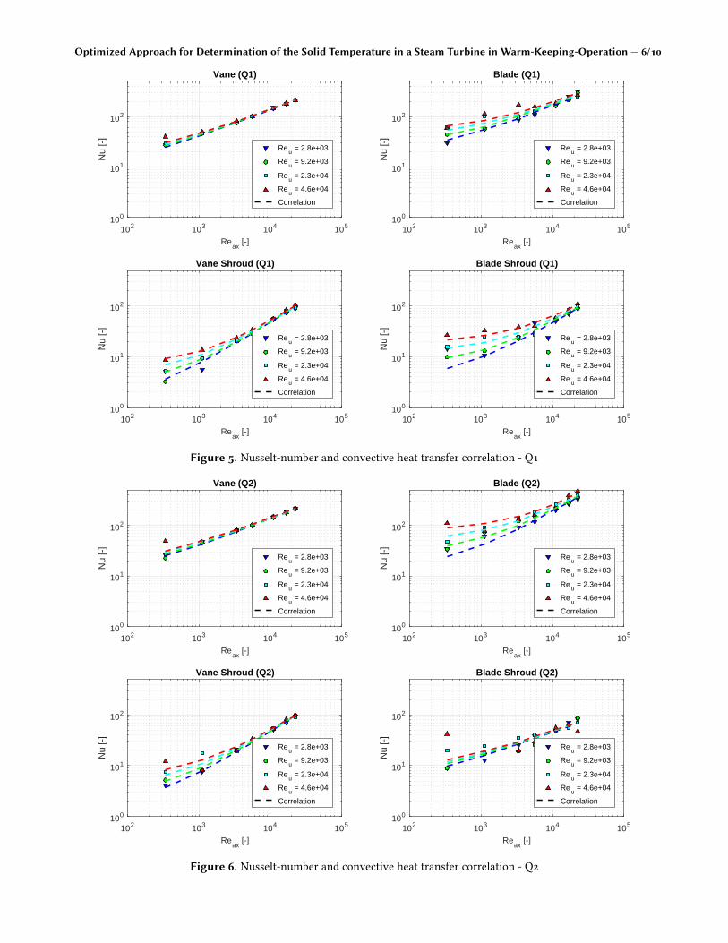
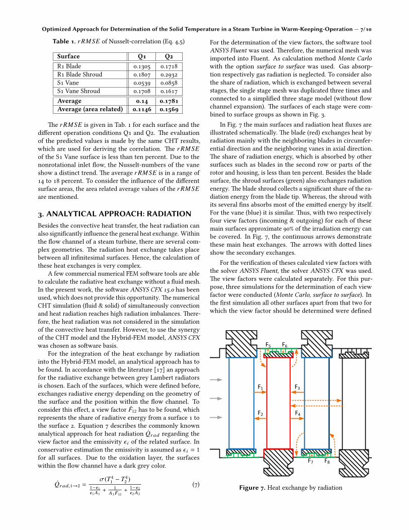
For the development of the convective heat transfer correla-tion for the warm-keeping process in two di�erent operations(Q1 & Q2) a physical correlation approach is used. �e inves-tigations have shown that Reax & Reu are the dominatingparameters for the description of the Nusselt-number. �ere-fore, a Nusselt-approach Nui (Eq. 5) was chosen, includingempirical factors a, b1 and b2 as well as the sum of bothReynolds-numbers and the Prandtl-number, to consider the�uid properties.
Nui = ai (Reb1iu, i + Reb2i
ax, i )Pr1/3 (5)For each surface i and each operation condition (Q1 or Q2)one Nusselt-correlation is de�ned by individual empiricalfactors ai , b1i and b2i . �ese coe�cients are determinedby a minimization of the residual sum of squares based onthe CHT results. �e Nusselt-correlation of Eq. 5 is plo�edin Fig. 5 for the conventional rotation direction (Q1) and inFig. 6 for the reversed rotation direction (Q2). �ese �guresalso show the numerically calculated Nusselt-numbers forthe convective heat transfer over the axial Reynolds-numberwith logarithmic scaled axes. In accordance to the �ndings ofthe �ow analysis [9], the numerical results are in�uenced bysecondary �ow structures. In general, the Nusselt-numberrises with increasing axial Reynolds-number and also withincreasing circumferential Reynolds-number. Because of thesingle stage model structure, the vane is only in�uencedby the rotational speed when the axial Reynolds-number isextremely low. �e blade shows a distinct dependency onthe rotational speed. However, kinks in the Nusselt-numbertrend can be observed due to the secondary �ow phenomena.In the vane and blade shroud, no distinct distribution of thecalculated Nusselt-numbers can be found, especially for thereversed rotational direction (Q2).
�e aim of the Nusselt-correlation is to reproduce thetrend of the heat transfer based on physical relations. �us,the correlation is not able to accurately describe the irreg-ularities regarding changing vortex structures. To evaluatethe accuracy of the correlation, the relative root mean squareerror r RMSE is introduced in Eq. 6, which represents therelative average deviation of the ��ed response value y(xi )from the original data value yi .
r RMSE =
√√1n
n∑i=1
(yi − y(xi )
yi
)2(6)
Optimized Approach for Determination of the Solid Temperature in a Steam Turbine in Warm-Keeping-Operation — 6/10
102 103 104 105
Reax
[-]
100
101
102
Nu
[-]
Blade (Q1)
Reu = 2.8e+03
Reu = 9.2e+03
Reu = 2.3e+04
Reu = 4.6e+04
Correlation
102 103 104 105
Reax
[-]
100
101
102
Nu
[-]
Blade Shroud (Q1)
Reu = 2.8e+03
Reu = 9.2e+03
Reu = 2.3e+04
Reu = 4.6e+04
Correlation
102 103 104 105
Reax
[-]
100
101
102
Nu
[-]
Vane Shroud (Q1)
Reu = 2.8e+03
Reu = 9.2e+03
Reu = 2.3e+04
Reu = 4.6e+04
Correlation
102 103 104 105
Reax
[-]
100
101
102
Nu
[-]
Vane (Q1)
Reu = 2.8e+03
Reu = 9.2e+03
Reu = 2.3e+04
Reu = 4.6e+04
Correlation
Figure 5. Nusselt-number and convective heat transfer correlation - Q1
102 103 104 105
Reax
[-]
100
101
102
Nu
[-]
Blade (Q2)
Reu = 2.8e+03
Reu = 9.2e+03
Reu = 2.3e+04
Reu = 4.6e+04
Correlation
102 103 104 105
Reax
[-]
100
101
102
Nu
[-]
Blade Shroud (Q2)
Reu = 2.8e+03
Reu = 9.2e+03
Reu = 2.3e+04
Reu = 4.6e+04
Correlation
102 103 104 105
Reax
[-]
100
101
102
Nu
[-]
Vane Shroud (Q2)
Reu = 2.8e+03
Reu = 9.2e+03
Reu = 2.3e+04
Reu = 4.6e+04
Correlation
102 103 104 105
Reax
[-]
100
101
102
Nu
[-]
Vane (Q2)
Reu = 2.8e+03
Reu = 9.2e+03
Reu = 2.3e+04
Reu = 4.6e+04
Correlation
Figure 6. Nusselt-number and convective heat transfer correlation - Q2
Optimized Approach for Determination of the Solid Temperature in a Steam Turbine in Warm-Keeping-Operation — 7/10
Table 1. r RMSE of Nusselt-correlation (Eq. 4,5)
Surface Q1 Q2R1 Blade 0.1305 0.1718R1 Blade Shroud 0.1807 0.2932S1 Vane 0.0539 0.0858S1 Vane Shroud 0.1708 0.1617Average 0.14 0.1781Average (area related) 0.1146 0.1569
�e r RMSE is given in Tab. 1 for each surface and thedi�erent operation conditions Q1 and Q2. �e evaluationof the predicted values is made by the same CHT results,which are used for deriving the correlation. �e r RMSEof the S1 Vane surface is less than ten percent. Due to thenonrotational inlet �ow, the Nusselt-numbers of the vaneshow a distinct trend. �e average r RMSE is in a range of14 to 18 percent. To consider the in�uence of the di�erentsurface areas, the area related average values of the r RMSEare mentioned.
3. ANALYTICAL APPROACH: RADIATIONBesides the convective heat transfer, the heat radiation canalso signi�cantly in�uence the general heat exchange. Withinthe �ow channel of a steam turbine, there are several com-plex geometries. �e radiation heat exchange takes placebetween all in�nitesimal surfaces. Hence, the calculation ofthese heat exchanges is very complex.
A few commercial numerical FEM so�ware tools are ableto calculate the radiative heat exchange without a �uid mesh.In the present work, the so�ware ANSYS CFX 15.0 has beenused, which does not provide this opportunity. �e numericalCHT simulation (�uid & solid) of simultaneously convectionand heat radiation reaches high radiation imbalances. �ere-fore, the heat radiation was not considered in the simulationof the convective heat transfer. However, to use the synergyof the CHT model and the Hybrid-FEM model, ANSYS CFXwas chosen as so�ware basis.
For the integration of the heat exchange by radiationinto the Hybrid-FEM model, an analytical approach has tobe found. In accordance with the literature [17] an approachfor the radiative exchange between grey Lambert radiatorsis chosen. Each of the surfaces, which were de�ned before,exchanges radiative energy depending on the geometry ofthe surface and the position within the �ow channel. Toconsider this e�ect, a view factor F12 has to be found, whichrepresents the share of radiative energy from a surface 1 tothe surface 2. Equation 7 describes the commonly knownanalytical approach for heat radiation Qrad regarding theview factor and the emissivity ε i of the related surface. Inconservative estimation the emissivity is assumed as ε i = 1for all surfaces. Due to the oxidation layer, the surfaceswithin the �ow channel have a dark grey color.
Qrad,1→2 =σ(T4
1 − T42 )
1−ε1ε1A1
+ 1A1 F12
+ 1−ε2ε2A2
(7)
For the determination of the view factors, the so�ware toolANSYS Fluent was used. �erefore, the numerical mesh wasimported into Fluent. As calculation method Monte Carlowith the option surface to surface was used. Gas absorp-tion respectively gas radiation is neglected. To consider alsothe share of radiation, which is exchanged between severalstages, the single stage mesh was duplicated three times andconnected to a simpli�ed three stage model (without �owchannel expansion). �e surfaces of each stage were com-bined to surface groups as shown in Fig. 3.
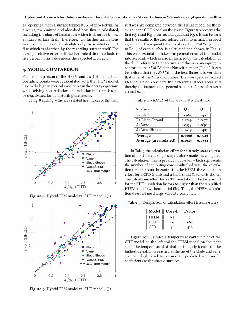
In Fig. 7 the main surfaces and radiation heat �uxes areillustrated schematically. �e blade (red) exchanges heat byradiation mainly with the neighboring blades in circumfer-ential direction and the neighboring vanes in axial direction.�e share of radiation energy, which is absorbed by othersurfaces such as blades in the second row or parts of therotor and housing, is less than ten percent. Besides the bladesurface, the shroud surfaces (green) also exchanges radiationenergy. �e blade shroud collects a signi�cant share of the ra-diation energy from the blade tip. Whereas, the shroud withits several �ns absorbs most of the emi�ed energy by itself.For the vane (blue) it is similar. �us, with two respectivelyfour view factors (incoming & outgoing) for each of thesemain surfaces approximate 90% of the irradiation energy canbe covered. In Fig. 7, the continuous arrows demonstratethese main heat exchanges. �e arrows with do�ed linesshow the secondary exchanges.
For the veri�cation of theses calculated view factors withthe solver ANSYS Fluent, the solver ANSYS CFX was used.�e view factors were calculated separately. For this pur-pose, three simulations for the determination of each viewfactor were conducted (Monte Carlo, surface to surface). Inthe �rst simulation all other surfaces apart from that two forwhich the view factor should be determined were de�ned
ϕ=0.02 ϕ=0.02
ϕ=0.20ϕ=0.19
F1 F3
F2 F4
F5 F6
F7 F8
Figure 7. Heat exchange by radiation
Optimized Approach for Determination of the Solid Temperature in a Steam Turbine in Warm-Keeping-Operation — 8/10
as ”openings” with a surface temperature of zero Kelvin. Asa result, the emi�ed and absorbed heat �ux is calculated,including the share of irradiation which is absorbed by theemi�ing surface itself. �erefore, two further simulationswere conducted to each calculate only the irradiation heat�ux which is absorbed by the regarding surface itself. �eaverage relative error of these two calculation methods is�ve percent. �is value meets the expected accuracy.
4. MODEL COMPARISONFor the comparison of the HFEM and the CHT model, alloperating points were recalculated with the HFEM model.Due to the high numerical imbalances in the energy equationswhile solving heat radiation, the radiation in�uence had tobe deactivated for no distorting the results.
In Fig. 8 and Fig. 9 the area related heat �uxes of the main
0 0.2 0.4 0.6 0.8 1_qi= _q0;i (CHT)
0
0.2
0.4
0.6
0.8
1
_q i=_q 0
;i(H
FEM
)
BladeVaneBlade ShroudVane Shroud15% error margin
Figure 8. Hybrid-FEM model vs. CHT model - Q1
0 0.2 0.4 0.6 0.8 1_qi= _q0;i (CHT)
0
0.2
0.4
0.6
0.8
1
_q i=_q 0
;i(H
FEM
)
BladeVaneBlade ShroudVane Shroud15% error margin
Figure 9. Hybrid-FEM model vs. CHT model - Q2
surfaces are compared between the HFEM model on the x-axis and the CHTmodel on the y-axis. Figure 8 represents the�rst (Q1) and Fig. 9 the second quadrant (Q2). It can be seenthat the results of the area related heat �uxes match in goodagreement. For a quantitative analysis, the r RMSE (similarto Eq.6) of each surface is calculated and shown in Tab. 2.�is error estimation takes the general error of the modelinto account, which is also in�uenced by the calculation ofthe �uid reference temperature and the area averaging, incontrast to the r RMSE of the Nusselt-number (Tab. 1). It canbe noticed that the r RMSE of the heat �uxes is lower thanthat only of the Nusselt-number. �e average area relatedr RMSE which considers the di�erent surfaces areas andthereby, the impact on the general heat transfer, is in between0.1 and 0.13.
Table 2. r RMSE of the area related heat �ux
Surface Q1 Q2R1 Blade 0.0983 0.1407R1 Blade Shroud 0.1729 0.2677S1 Vane 0.0533 0.0691S1 Vane Shroud 0.1819 0.1407Average 0.1266 0.1546Average (area related) 0.1027 0.1332
In Tab. 3 the calculation e�ort for a steady-state calcula-tion of the di�erent single stage turbine models is compared.�e calculation time is provided in core-h, which representsthe number of computing cores multiplied with the calcula-tion time in hours. In contrast to the HFEM, the calculatione�ort for a CFD (�uid) and a CHT (�uid & solid) is shown.�e calculation e�ort for a CFD simulation is factor 410 andfor the CHT simulation factor 660 higher than the simpli�edHFEM model (without initial �le). �us, the HFEM calcula-tion does not need large-capacity computers.
Table 3. Comparison of calculation e�ort (steady-state)
Model Core-h FactorHFEM 0.1 1CHT 66 660CFD 41 410
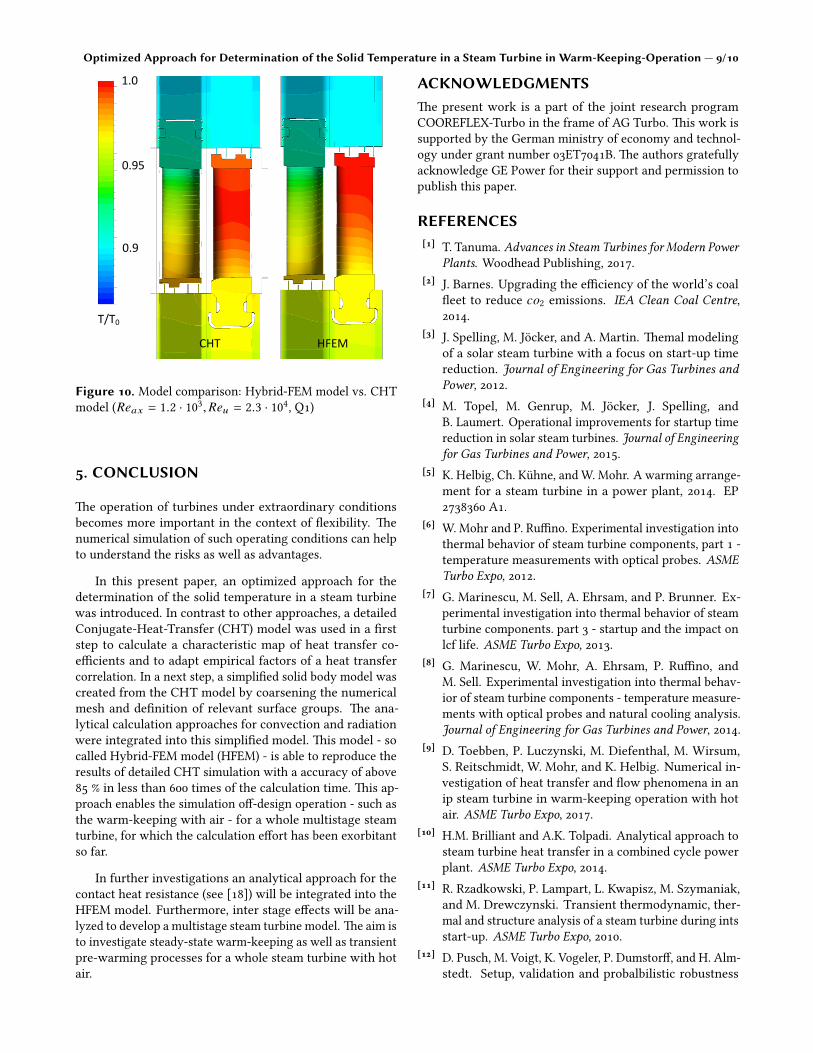
Figure 10 illustrates a temperature contour plot of theCHT model on the le� and the HFEM model on the rightside. �e temperature distribution is nearly identical. �ehighest deviation is reached at the tip of the blade and vane,due to the highest relative error of the predicted heat transfercoe�cients at the shroud surfaces.
Optimized Approach for Determination of the Solid Temperature in a Steam Turbine in Warm-Keeping-Operation — 9/10
CHT HFEM
1.0
0.9
0.95
T/T0
Figure 10. Model comparison: Hybrid-FEM model vs. CHTmodel (Reax = 1.2 · 103,Reu = 2.3 · 104, Q1)
5. CONCLUSION
�e operation of turbines under extraordinary conditionsbecomes more important in the context of �exibility. �enumerical simulation of such operating conditions can helpto understand the risks as well as advantages.
In this present paper, an optimized approach for thedetermination of the solid temperature in a steam turbinewas introduced. In contrast to other approaches, a detailedConjugate-Heat-Transfer (CHT) model was used in a �rststep to calculate a characteristic map of heat transfer co-e�cients and to adapt empirical factors of a heat transfercorrelation. In a next step, a simpli�ed solid body model wascreated from the CHT model by coarsening the numericalmesh and de�nition of relevant surface groups. �e ana-lytical calculation approaches for convection and radiationwere integrated into this simpli�ed model. �is model - socalled Hybrid-FEM model (HFEM) - is able to reproduce theresults of detailed CHT simulation with a accuracy of above85 % in less than 600 times of the calculation time. �is ap-proach enables the simulation o�-design operation - such asthe warm-keeping with air - for a whole multistage steamturbine, for which the calculation e�ort has been exorbitantso far.
In further investigations an analytical approach for thecontact heat resistance (see [18]) will be integrated into theHFEM model. Furthermore, inter stage e�ects will be ana-lyzed to develop a multistage steam turbine model. �e aim isto investigate steady-state warm-keeping as well as transientpre-warming processes for a whole steam turbine with hotair.
ACKNOWLEDGMENTS�e present work is a part of the joint research programCOOREFLEX-Turbo in the frame of AG Turbo. �is work issupported by the German ministry of economy and technol-ogy under grant number 03ET7041B. �e authors gratefullyacknowledge GE Power for their support and permission topublish this paper.
REFERENCES[1] T. Tanuma. Advances in Steam Turbines for Modern Power
Plants. Woodhead Publishing, 2017.[2] J. Barnes. Upgrading the e�ciency of the world’s coal
�eet to reduce co2 emissions. IEA Clean Coal Centre,2014.
[3] J. Spelling, M. Jocker, and A. Martin. �emal modelingof a solar steam turbine with a focus on start-up timereduction. Journal of Engineering for Gas Turbines andPower, 2012.
[4] M. Topel, M. Genrup, M. Jocker, J. Spelling, andB. Laumert. Operational improvements for startup timereduction in solar steam turbines. Journal of Engineeringfor Gas Turbines and Power, 2015.
[5] K. Helbig, Ch. Kuhne, andW. Mohr. A warming arrange-ment for a steam turbine in a power plant, 2014. EP2738360 A1.
[6] W. Mohr and P. Ru�no. Experimental investigation intothermal behavior of steam turbine components, part 1 -temperature measurements with optical probes. ASMETurbo Expo, 2012.
[7] G. Marinescu, M. Sell, A. Ehrsam, and P. Brunner. Ex-perimental investigation into thermal behavior of steamturbine components. part 3 - startup and the impact onlcf life. ASME Turbo Expo, 2013.
[8] G. Marinescu, W. Mohr, A. Ehrsam, P. Ru�no, andM. Sell. Experimental investigation into thermal behav-ior of steam turbine components - temperature measure-ments with optical probes and natural cooling analysis.Journal of Engineering for Gas Turbines and Power, 2014.
[9] D. Toebben, P. Luczynski, M. Diefenthal, M. Wirsum,S. Reitschmidt, W. Mohr, and K. Helbig. Numerical in-vestigation of heat transfer and �ow phenomena in anip steam turbine in warm-keeping operation with hotair. ASME Turbo Expo, 2017.
[10] H.M. Brilliant and A.K. Tolpadi. Analytical approach tosteam turbine heat transfer in a combined cycle powerplant. ASME Turbo Expo, 2014.
[11] R. Rzadkowski, P. Lampart, L. Kwapisz, M. Szymaniak,and M. Drewczynski. Transient thermodynamic, ther-mal and structure analysis of a steam turbine during intsstart-up. ASME Turbo Expo, 2010.
[12] D. Pusch, M. Voigt, K. Vogeler, P. Dumstor�, and H. Alm-stedt. Setup, validation and probalbilistic robustness
Optimized Approach for Determination of the Solid Temperature in a Steam Turbine in Warm-Keeping-Operation — 10/10
estimation of a model for prediction of lcf in steam tur-bine rotors. ASME Turbo Expo, 2016.
[13] W. Traupel. �ermische Turbomaschinen. Bd. 1. Springer,Berlin, 1988.
[14] L. Moroz, B. Frolov, and R. Kochurov. Steam turbinerotor transient thermo-structural analysis and lifetimeprediction. ASME Turbo Expo, 2016.
[15] W.Z. Wang, P. Buhl, A. Klenk, and Y.Z. Liu. �e e�ect ofin-service steam temperature transients on the damagebehavior of steam turbine rotor. International Journal ofFatique, 2016.
[16] D. Born, P. Stein, G. Marinescu, S. Koch, and D. Schu-macher. �ermal modelling of an intermediate pressuresteam turbine by means of conjugate heat transfer - sim-ulation and validation. ASME Turbo Expo, 2016.
[17] H. D. Baehr and K. Stephan. Heat and Mass Tranfer.Springer-Verlag Berlin Heidelberg, 2011.
[18] D. Toebben, X. E. R. de Graaf, P. Luczynski, M. Wirsum,W.Mohr, and K. Helbig. Test rig for applied experimentalinvestigations of the thermal contact resistance at theblade-rotor-connection in a steam turbine. ISROMAC,2017.