Embed Size (px)
Citation preview
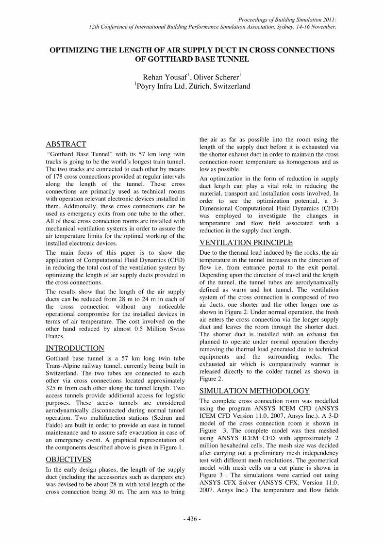
OPTIMIZING THE LENGTH OF AIR SUPPLY DUCT IN CROSS CONNECTIONS OF GOTTHARD BASE TUNNEL
Rehan Yousaf1, Oliver Scherer1
1Pöyry Infra Ltd, Zürich, Switzerland
ABSTRACT “Gotthard Base Tunnel” with its 57 km long twin tracks is going to be the world’s longest train tunnel. The two tracks are connected to each other by means of 178 cross connections provided at regular intervals along the length of the tunnel. These cross connections are primarily used as technical rooms with operation relevant electronic devices installed in them. Additionally, these cross connections can be used as emergency exits from one tube to the other. All of these cross connection rooms are installed with mechanical ventilation systems in order to assure the air temperature limits for the optimal working of the installed electronic devices. The main focus of this paper is to show the application of Computational Fluid Dynamics (CFD) in reducing the total cost of the ventilation system by optimizing the length of air supply ducts provided in the cross connections. The results show that the length of the air supply ducts can be reduced from 28 m to 24 m in each of the cross connection without any noticeable operational compromise for the installed devices in terms of air temperature. The cost involved on the other hand reduced by almost 0.5 Million Swiss Francs.
INTRODUCTION Gotthard base tunnel is a 57 km long twin tube Trans-Alpine railway tunnel, currently being built in Switzerland. The two tubes are connected to each other via cross connections located approximately 325 m from each other along the tunnel length. Two access tunnels provide additional access for logistic purposes. These access tunnels are considered aerodynamically disconnected during normal tunnel operation. Two multifunction stations (Sedrun and Faido) are built in order to provide an ease in tunnel maintenance and to assure safe evacuation in case of an emergency event. A graphical representation of the components described above is given in Figure 1.
OBJECTIVES In the early design phases, the length of the supply duct (including the accessories such as dampers etc) was devised to be about 28 m with total length of the cross connection being 30 m. The aim was to bring
the air as far as possible into the room using the length of the supply duct before it is exhausted via the shorter exhaust duct in order to maintain the cross connection room temperature as homogenous and as low as possible. An optimization in the form of reduction in supply duct length can play a vital role in reducing the material, transport and installation costs involved. In order to see the optimization potential, a 3-Dimensional Computational Fluid Dynamics (CFD) was employed to investigate the changes in temperature and flow field associated with a reduction in the supply duct length.
VENTILATION PRINCIPLE Due to the thermal load induced by the rocks, the air temperature in the tunnel increases in the direction of flow i.e. from entrance portal to the exit portal. Depending upon the direction of travel and the length of the tunnel, the tunnel tubes are aerodynamically defined as warm and hot tunnel. The ventilation system of the cross connection is composed of two air ducts, one shorter and the other longer one as shown in Figure 2. Under normal operation, the fresh air enters the cross connection via the longer supply duct and leaves the room through the shorter duct. The shorter duct is installed with an exhaust fan planned to operate under normal operation thereby removing the thermal load generated due to technical equipments and the surrounding rocks. The exhausted air which is comparatively warmer is released directly to the colder tunnel as shown in Figure 2.
SIMULATION METHODOLOGY The complete cross connection room was modelled using the program ANSYS ICEM CFD (ANSYS ICEM CFD Version 11.0, 2007, Ansys Inc.). A 3-D model of the cross connection room is shown in Figure 3. The complete model was then meshed using ANSYS ICEM CFD with approximately 2 million hexahedral cells. The mesh size was decided after carrying out a preliminary mesh independency test with different mesh resolutions. The geometrical model with mesh cells on a cut plane is shown in Figure 3 . The simulations were carried out using ANSYS CFX Solver (ANSYS CFX, Version 11.0, 2007, Ansys Inc.) The temperature and flow fields
Proceedings of Building Simulation 2011: 12th Conference of International Building Performance Simulation Association, Sydney, 14-16 November.
- 436 -

were compared for reduced supply duct lengths of 24 m and 20 m with that of complete supply duct length of 28 m.
Simulation Parameters and Boundary Conditions The meshed model was setup for the flow physics using the software ANSYS CFX (ANSYS CFX, Version 11.0, 2007, Ansys Inc.). The ideal gas law was used to capture the temperature dependent flows. Steady state simulations were carried out by solving Navier Stokes equations (Versteeg, Malalasekera, 1995). In order to resolve the turbulence induced effects, SST turbulence model (ANSYS CFX, Version 11.0, 2007, Ansys Inc.) was employed. The aero- and thermodynamic conditions were chosen for a cross connection room located centrally along the length of the Gotthard Base Tunnel. The surface temperature of the cross connection room (caved portion) was set to 35°C where as the surface temperature of the front and back walls adjacent to the warmer and colder tunnel were defined to have a surface temperature of 30°C. Technical equipments were modelled as internal load of 7 kW. Two technical equipment cupboards were modelled as flow resistances located near to each end of the cross connection room. The walls of the supply and exhaust ducts were modelled as adiabatic walls. The exhaust was modelled as an outlet with a constant volume flow of 2.2 m³/s. The air enters the supply duct via an opening with air temperature of 30°C.
Computational Resources The simulations are carried out on a intel xeon cluster with 8, 2.66 GHz parallel processors. One simulation run took about 13 hours of wall clock time for carrying out 2000 iterations.
RESULTS The simulation results were considered as valid converged results once the RMS residuals fell for momentum, mass and energy equation fell below 1e-5. The results are presented as a) iso-surface of 4 m/s velocity with overlay of temperature b) heat transfer coefficient at the technical equipment on the rear and front sides and c) temperature averaged cross sections located every 2 m along the length of the room (cross connection).
Iso surfaces of velocity Figure 4 show the iso surface of 4 m/s velocity with an overlay of temperature for the three different variations. The value of 4 m/s is chosen arbitrarily for comparison purposes. In its basic variation (variation 0), the jet of air coming out of the supply duct impinges the wall directly with the temperature of 30.5°C. With a reduction of 4 m in supply duct length (variation 1), the incoming air (via supply duct) gets mixed with the room air and reaches the end of the cross connection with a temperature of
31°C. It is however seen that the impulse effect is still dominant and the temperature of the incoming air is influenced by +0.5 K. With a reduction of 8 m in the supply duct length (Variation 2), it is seen that the surrounding warmer air gets quickly mixed up with the air coming through the supply duct. The impulse effect is still to be seen but the temperature at the impingement point is about 31.6°C.
Heat Transfer Coefficients Figure 5 show the perspective views of the cross connection room with heat transfer coefficients plotted on the surface of the technical equipment. It can be seen that a reduction of 8 m in the supply duct length increases the heat transfer (shown by higher heat transfer coefficients) on the “Front Side” but has little influence on the “Rear Side” of the technical equipments when compared with variations 0 and 1.
Temperature Figure 6 is a graphical representation of temperatures averaged on a cross section plane at regular interval of 2 m along the length of cross connection room. The temperature curve is a result of linear interpolation of the averaged values. The temperature curves are shown as function of cross connection length for each of the three variations. It is seen that with a supply length of 28 m (variation 0), the air delivered is about 0.5 K colder near to the end of the cross connection room compared to air supplied using supply duct length of 24 m (variation 1) and supply duct length of 20 m (variation 2). The 0.5 K temperature change induced due to longer supply duct (variation 0) is however levelled out within the first meter and the longer supply duct brings no additional advantage in keeping the temperature of the cross connection room lower as compared to the variations 1 and 2. With shorter supply duct lengths (variation 1 and 2), the air takes away the heat from the technical equipments on its way towards the end of the cross connection room, returns back and removes again the heat from the technical equipment but with a lower heat transfer rate due to lower temperature difference.
CONCLUSIONS On the basis of the results provided in earlier sections, it is seen that reducing the supply duct length has no negative effect instead the heat transfer from the surface of technical equipment increases with a decrease in the supply duct length. A supply duct reduction of 4 m proves to be more effective due to its linear temperature increase and lower overall temperature in the cross connection. A decrease of supply duct length by 8 m leads to satisfying results with the exception that the temperature near to the start of the cross section is higher. This is due to the fact that the air entering the cross connection starts to get warm on its way to the end of cross connection due to the shorter supply duct length and on its way
Proceedings of Building Simulation 2011: 12th Conference of International Building Performance Simulation Association, Sydney, 14-16 November.
- 437 -

back after impingement cumulate near the entrance (start) of the cross connection. A reduction in supply duct length is a cost effective measure as long as it does not influence the aero- and thermodynamic conditions such as air movement and temperatures in the cross connection room. A drastic increase in temperature can cause a threat to the functionality of the installed technical equipment. It is seen from the results that a reduction of 8 m in supply duct length indicates the tendency of increase in average temperature. Due to the uncertainties in the boundary conditions such as inlet air temperature, rock local temperature, variation in internal thermal loads etc, it was decided to reduce the length of supply duct by 4 m thereby saving the costs by approximately 0.5 million Swiss Francs in the final design.
ACKNOWLEDGEMENT The results published in this paper are courtesy of the consortium "Alp-Transit Gotthard" (ATG, 2011). The authors would like to thank ATG for their allowance for publication. REFERENCES Alp Transit Gotthard; Website: www.alptransit.ch. ANSYS CFX, Version 11, Ansys Inc.
(www.ansys.com) ANSYS ICEM CFD, Version 11, Ansys Inc.
(www.ansys.com) H.K.Versteeg and W.Malalasekera, An introduction
to Computational Fluid Dynamics, The Finite Volume Method, Prentice Hall, 1995.
Proceedings of Building Simulation 2011: 12th Conference of International Building Performance Simulation Association, Sydney, 14-16 November.
- 438 -
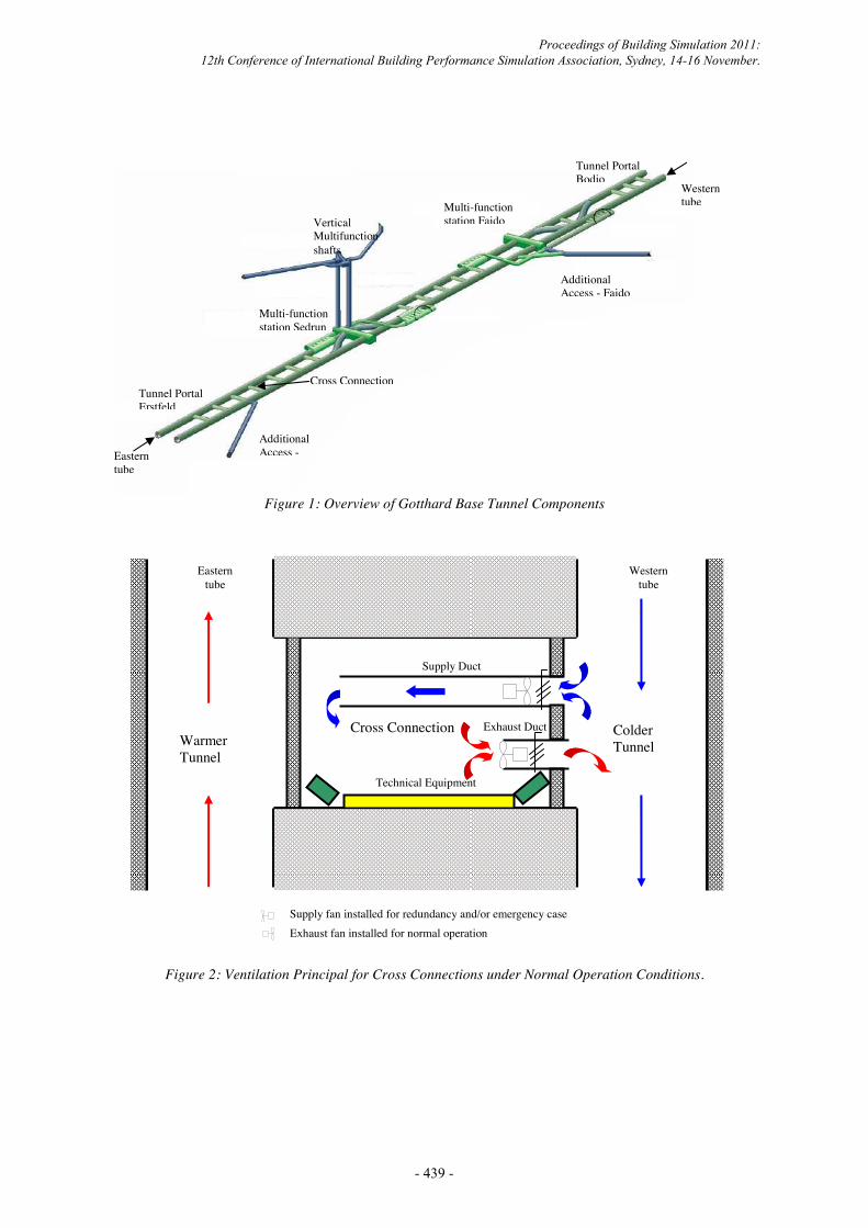
Figure 1: Overview of Gotthard Base Tunnel Components
Figure 2: Ventilation Principal for Cross Connections under Normal Operation Conditions.
Eastern tube
Western tube
Warmer Tunnel
Colder Tunnel
Cross Connection
Supply Duct
Exhaust Duct
Technical Equipment
Supply fan installed for redundancy and/or emergency case Exhaust fan installed for normal operation
Additional Access -
Additional Access - Faido
Tunnel Portal Bodio
Multi-function station Faido
Multi-function station Sedrun
Tunnel Portal Erstfeld
Vertical Multifunction shafts
Cross Connection
Eastern tube
Western tube
Proceedings of Building Simulation 2011: 12th Conference of International Building Performance Simulation Association, Sydney, 14-16 November.
- 439 -

Figure 3: 3-Dimensional model of the cross connection with mesh cut plane.
Figure 4: Iso-Surface of 4 [m/s] velocity with an overlay of temperature.
Hexahedral cells at a cut plane
Supply Duct
Exhaust Duct
thermal load
Technical Equipment Cupboard 1
Technical Equipment Cupboard 2
Variation 0: Supply duct 28 m long
Variation 1: Supply duct 24 m long
Variation 2: Supply duct 20 m long
Proceedings of Building Simulation 2011: 12th Conference of International Building Performance Simulation Association, Sydney, 14-16 November.
- 440 -

Figure 5: Heat transfer coefficients plotted on the technical equipment with thermal load of 7 kW.
Figure 6: Average Temperature in the cross connection (excluding air temperature in supply and exhaust duct) plotted at 2 m interval along the length of the room (cross connection)
30.5
31.0
31.5
32.0
32.5
33.0
33.5
34.0
34.5
0 5 10 15 20 25 30Length along the Cross Connection [m]
Tem
pera
ture
[°C
]
Variation 0 Variation 1 Variation 2
End
Star
t
Proceedings of Building Simulation 2011: 12th Conference of International Building Performance Simulation Association, Sydney, 14-16 November.
- 441 -