Embed Size (px)
Citation preview
Presented by: Shefali Gupta
Kurukshetra University, Kurukshetra
OPTIMIZING THE PERFORMANCE OF
MEMS ELECTROSTATIC COMB DRIVE
ACTUATOR WITH DIFFERENT
FLEXURE SPRINGS
Microelectromechanical systems (MEMS) are very small devices or
groups of devices that can integrate both mechanical and electrical
components.
MEMS can be constructed on one chip that contains one or more
micro-components and the electrical circuitry for inputs and
outputs of the components.
The term MEMS first started being used in the 1980’s.
Microcomponents make the system faster, more reliable, cheaper
and more capable.
MEMS
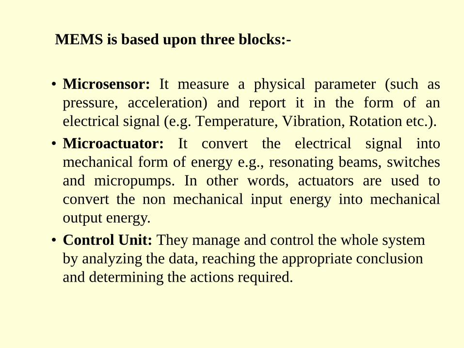
MEMS is based upon three blocks:-
• Microsensor: It measure a physical parameter (such as
pressure, acceleration) and report it in the form of an
electrical signal (e.g. Temperature, Vibration, Rotation etc.).
• Microactuator: It convert the electrical signal into
mechanical form of energy e.g., resonating beams, switches
and micropumps. In other words, actuators are used to
convert the non mechanical input energy into mechanical
output energy.
• Control Unit: They manage and control the whole system
by analyzing the data, reaching the appropriate conclusion
and determining the actions required.
Actuator
It converts non mechanical input energy into
mechanical output energy.
ELECTROSTATIC COMB DRIVE ACTUATOR
Comb Drive actuator is the main application of
Electrostatic Actuator
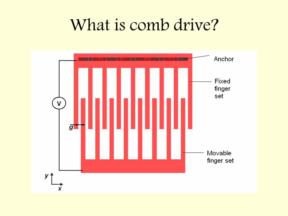
What is comb drive?
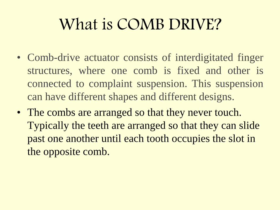
What is COMB DRIVE? • Comb-drive actuator consists of interdigitated finger
structures, where one comb is fixed and other is
connected to complaint suspension. This suspension
can have different shapes and different designs.
• The combs are arranged so that they never touch.
Typically the teeth are arranged so that they can slide
past one another until each tooth occupies the slot in
the opposite comb.
• Applying a potential difference across the comb
structure will result in deflection of the movable
comb structure, this deflection is due to generated
electrostatic forces in the system.
• The position of the movable fingers is controlled by
balance between electrostatic forces and the
mechanical forces. Mechanical forces are generated
through spring structures. They directly depend upon
the stiffness of the flexures. By changing the flexures,
mechanical forces changes which changes
displacement.
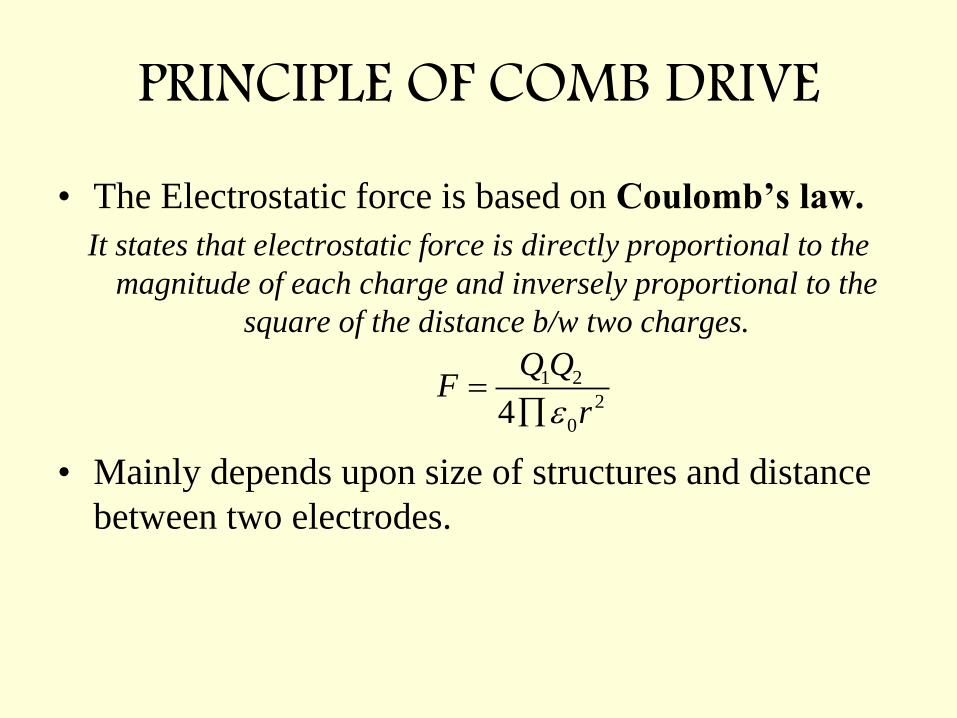
PRINCIPLE OF COMB DRIVE • The Electrostatic force is based on Coulomb’s law.
It states that electrostatic force is directly proportional to the
magnitude of each charge and inversely proportional to the
square of the distance b/w two charges.
• Mainly depends upon size of structures and distance
between two electrodes.
1 2
2
04
Q QF
r
APPLICATIONS • RESONATORS • ELECTROMECHANICAL FILTERS • OPTICAL SHUTTERS • MICROGRIPPERS • VOLTMETERS
OBJECTIVE
Large deflections at low actuation
voltage.
SPRING DESIGNS
1. FIXED – FIXED FLEXURE
2. CRAB LEG FLEXURE
3. FOLDED FLEXURE
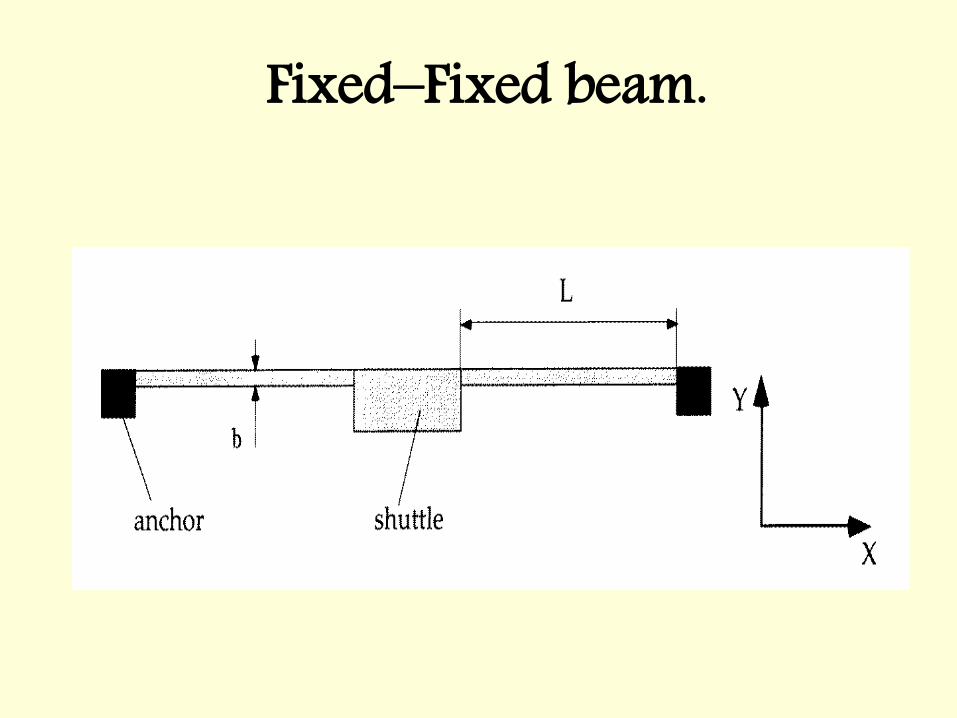
Fixed–Fixed beam.
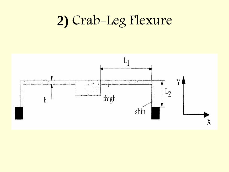
2) Crab-Leg Flexure
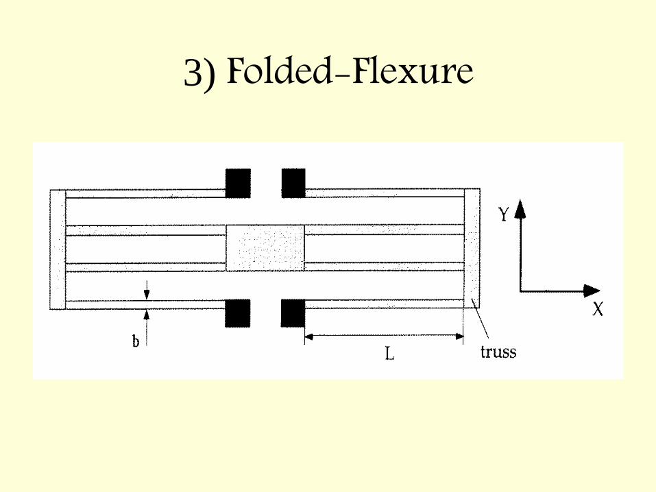
3) Folded-Flexure
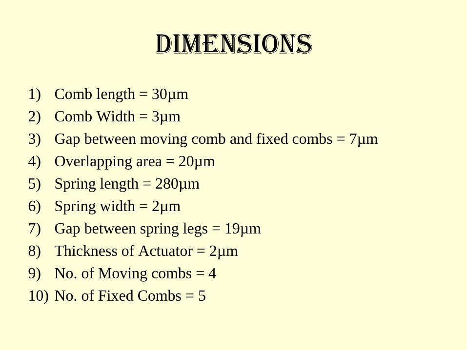
Dimensions
1) Comb length = 30µm
2) Comb Width = 3µm
3) Gap between moving comb and fixed combs = 7µm
4) Overlapping area = 20µm
5) Spring length = 280µm
6) Spring width = 2µm
7) Gap between spring legs = 19µm
8) Thickness of Actuator = 2µm
9) No. of Moving combs = 4
10) No. of Fixed Combs = 5
20n tV
Fel
g
32 ( )W
K EtL
0 02 ( )n t y yC
g
3 20 ( )2
n LV
Eg W
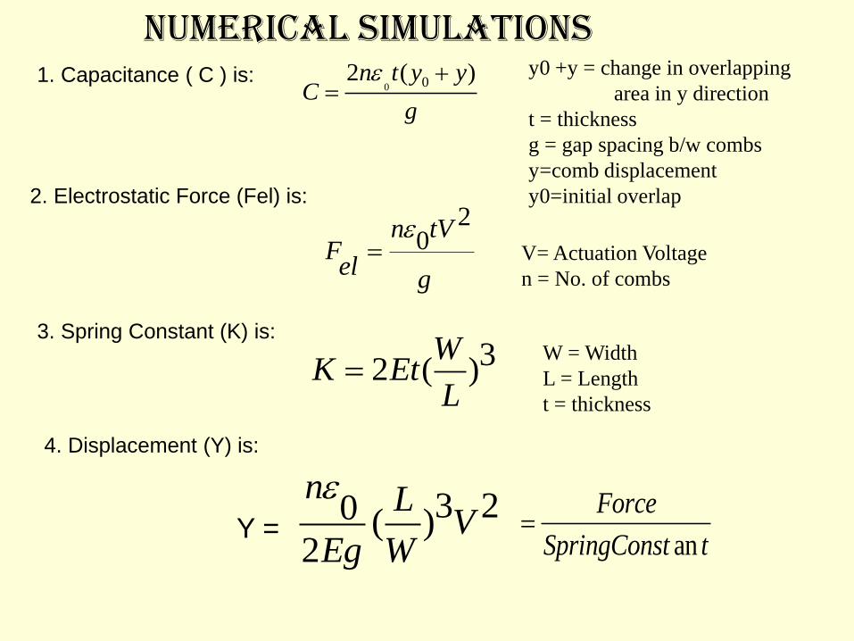
1. Capacitance ( C ) is: y0 +y = change in overlapping
area in y direction
t = thickness
g = gap spacing b/w combs
y=comb displacement
y0=initial overlap 2. Electrostatic Force (Fel) is:
V= Actuation Voltage
n = No. of combs
3. Spring Constant (K) is: W = Width
L = Length
t = thickness
4. Displacement (Y) is:
Y =
NUMERICAL SIMULATIONS
an
Force
SpringConst t
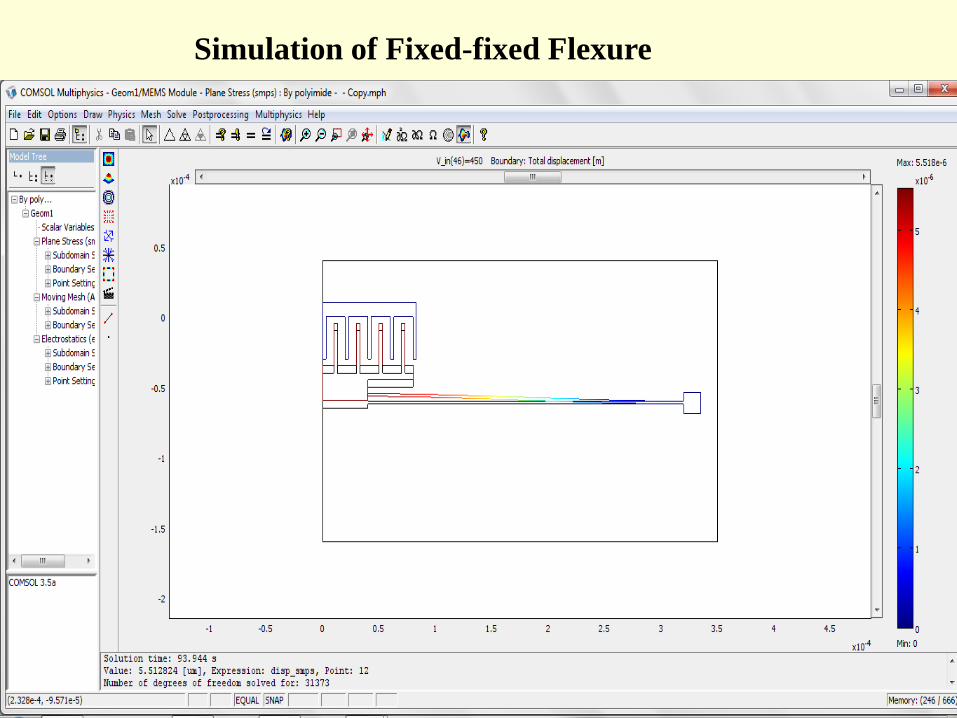
Simulation of Fixed-fixed Flexure
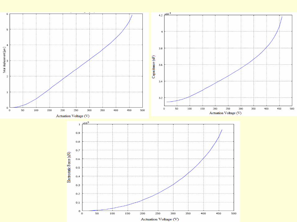
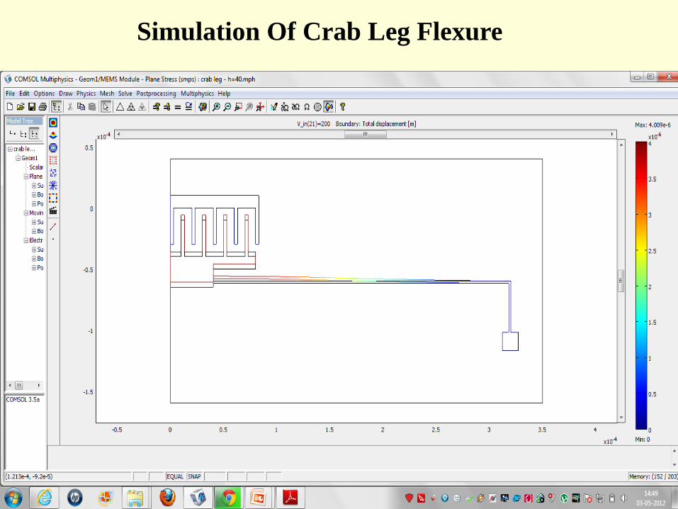
Simulation Of Crab Leg Flexure
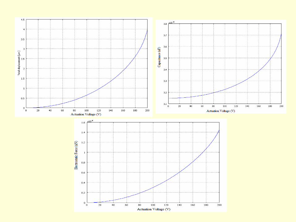
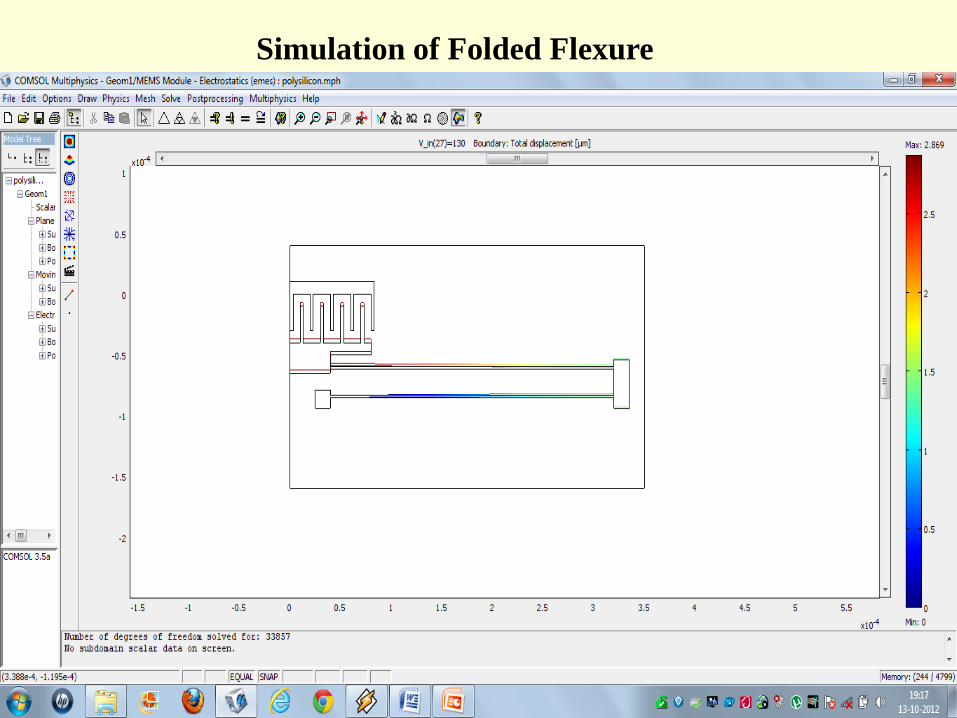
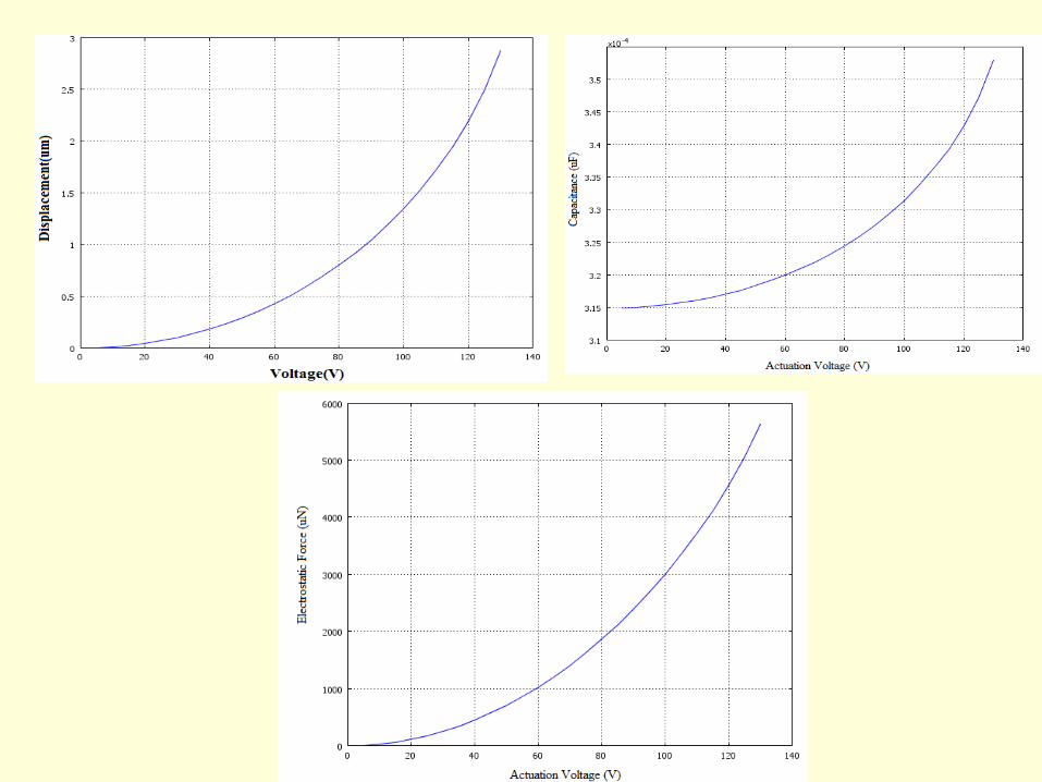
Simulation of Folded Flexure
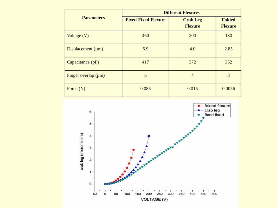
Parameters
Different Flexures
Fixed-Fixed Flexure Crab Leg
Flexure
Folded
Flexure
Voltage (V) 460 200 130
Displacement (µm) 5.9 4.0 2.85
Capacitance (pF) 417 372 352
Finger overlap (µm) 6 4 3
Force (N) 0.085 0.015 0.0056
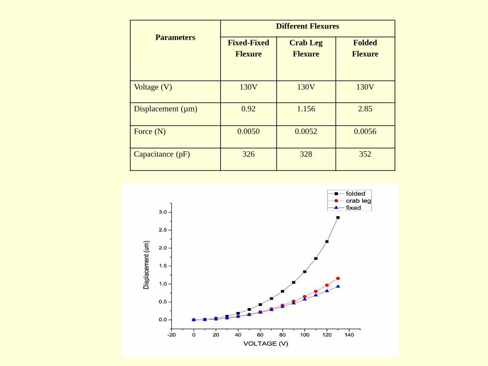
Parameters
Different Flexures
Fixed-Fixed
Flexure
Crab Leg
Flexure
Folded
Flexure
Voltage (V) 130V 130V 130V
Displacement (µm) 0.92 1.156 2.85
Force (N) 0.0050 0.0052 0.0056
Capacitance (pF) 326 328 352
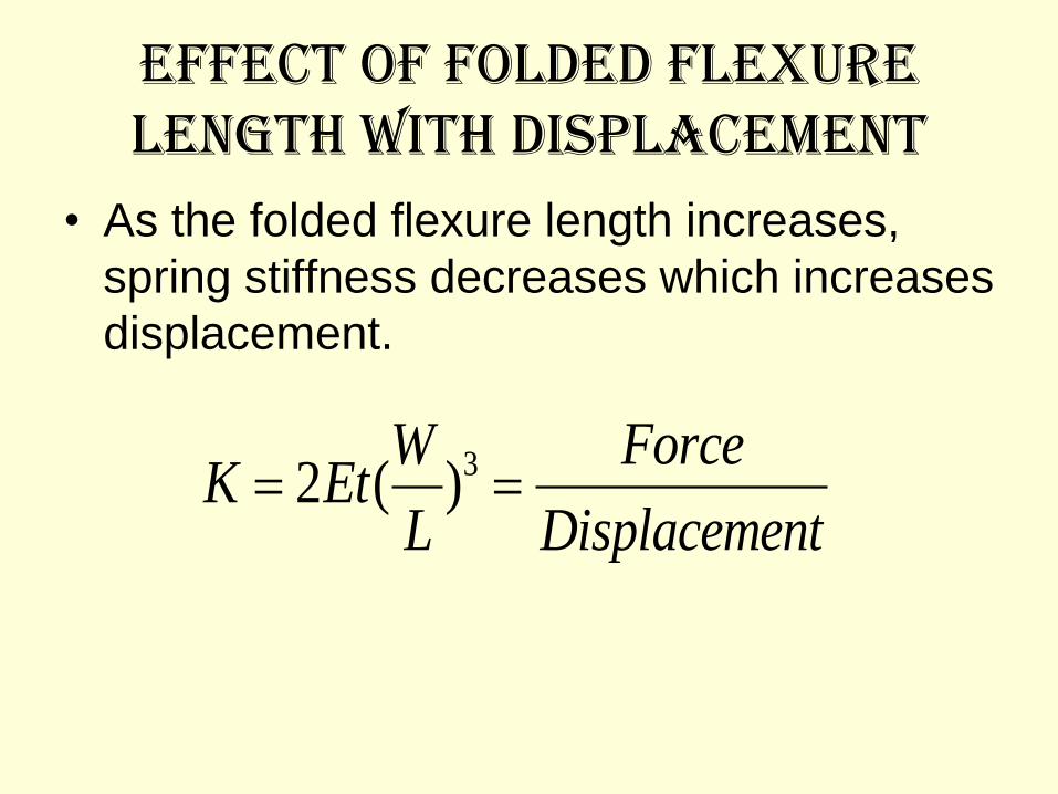
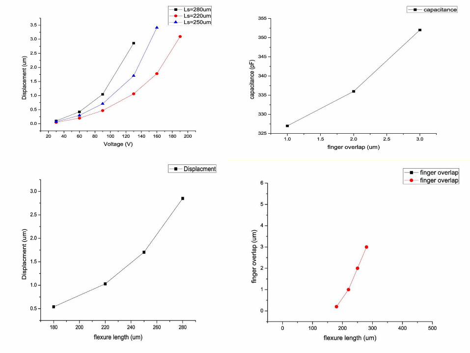
Effect of Folded Flexure length with displacement
• As the folded flexure length increases,
spring stiffness decreases which increases
displacement.
32 ( )W Force
K EtL Displacement
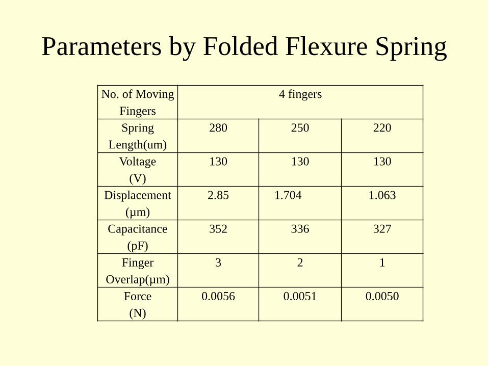
Parameters by Folded Flexure Spring
No. of Moving
Fingers
4 fingers
Spring
Length(um)
280 250 220
Voltage
(V)
130 130 130
Displacement
(µm)
2.85 1.704 1.063
Capacitance
(pF)
352 336 327
Finger
Overlap(µm)
3 2 1
Force
(N)
0.0056 0.0051 0.0050