Embed Size (px)
Citation preview
Democratic and Popular Republic of Algeria
-------------------------------------------------------------------
University of Kasdi Merbah – Ouargla
Faculty of Science and Technology and Matter Sciences Department of Mechanical Engineering
Dissertation
Professional Master
Domain: Science and Technology
Specialty: Energy
Title:
Publicly defended
On: .30./ 05/2017
Before the jury
President: Mr HECINI ...............................................................KMU Ouargla
Supervisor: Mr .DERGHOUT ZOHEIR ..................................KMU-Ouargla
Examiner:Mr. ZERROUK . ........................................................KMU Ouargla
Submitted by : Supervised by :
Kat Mohamed Ali Derghouth Zohir
Bourahla Benzeghmane
Academic year: 2016/2017
OPTIMIZTION AND INVESTIGATE OF AN AIR
CONDITIONING SYSTEM WITH LOW ENERGY
CONSUMPTION AND ADAPTED WITH LOCAL
CLIMATE
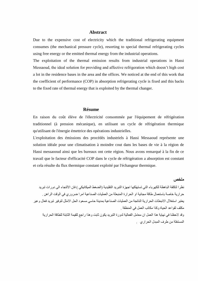
Abstract
Due to the expensive cost of electricity which the traditional refrigerating equipment
consumes (the mechanical pressure cycle), resorting to special thermal refrigerating cycles
using free energy or the emitted thermal energy from the industrial operations.
The exploitation of the thermal emission results from industrial operations in Hassi
Messaoud, the ideal solution for providing and affective refrigeration which doesn’t high cost
a lot in the residence bases in the area and the offices. We noticed at the end of this work that
the coefficient of performance (COP) in absorption refrigerating cycle is fixed and this backs
to the fixed rate of thermal energy that is exploited by the thermal changer.
Résume
En raison du coût élève de l'électricité consommée par l'équipement de réfrigération
traditionnel (à pression mécanique), en utilisant un cycle de réfrigération thermique
qu'utilisant de l'énergie émettrice des opérations industrielles.
L'exploitation des émissions des procédés industriels à Hassi Messaoud représente une
solution idéale pour une climatisation à moindre cout dans les bases de vie à la région de
Hassi messaooud ainsi que les bureaux ont cette région. Nous avons remarqué à la fin de ce
travail que le facteur d'efficacité COP dans le cycle de réfrigération a absorption est constant
et cela résulte du flux thermique constant exploité par l'échangeur thermique.
ملخص
فان االنخجاء انى دوراث حبزد (انضغظ انمكاوك )وظزا نخكهفت انباهظت نهكهزباء انخ حسخههكها اجهزة انخبزد انخقهدت
. حزارت خاصت باسخعمال طاقت مجاوت او انحزارة انمىبعثت مه انعمهاث انصىاعت امزا ضزوري ف انىقج انزاهه
عخبز اسخغالل االوبعثاث انحزارت انىاحجت مه انعمهاث انصىاعت بمدىت حاس مسعىد انحم االمثم نخىفز حبزد فعال وعز
. مكهف نقىاعد انحاة وكذا مكاحب انعمم ف انمىطقت
وقد الحظىا ف وهات هذا انعمم ان معامم انفعانت ندورة انخبزد كىن ثابج وهذا راجع نهقمت انثابخت نهطاقت انحزارت
.انمسخغهت مه طزف انمبدل انحزاري
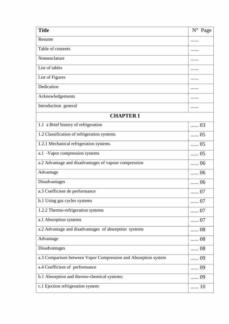
Title N° Page
Resume ......
Table of contents ......
Nomenclature ......
List of tables ......
List of Figures ......
Dedication ......
Acknowledgements ......
Introduction general ......
CHAPTER I
1.1 a Brief history of refrigeration ...... 03
1.2 Classification of refrigeration systems ...... 05
1.2.1 Mechanical refrigeration systems ...... 05
a.1 -Vapor compression systems ...... 05
a.2 Advantage and disadvantages of vapour compression ...... 06
Advantage ...... 06
Disadvantages ...... 06
a.3 Coefficient de performance ...... 07
b.1 Using gas cycles systems ...... 07
1.2.2 Thermo-refrigeration systems ...... 07
a.1 Absorption systems ...... 07
a.2 Advantage and disadvantages of absorption systems ...... 08
Advantage ...... 08
Disadvantages ...... 08
a.3 Comparison between Vapor Compression and Absorption system ...... 09
a.4 Coefficient of performance ...... 09
b.1 Absorption and thermo-chemical systems: ...... 09
c.1 Ejection refrigeration system: ...... 10
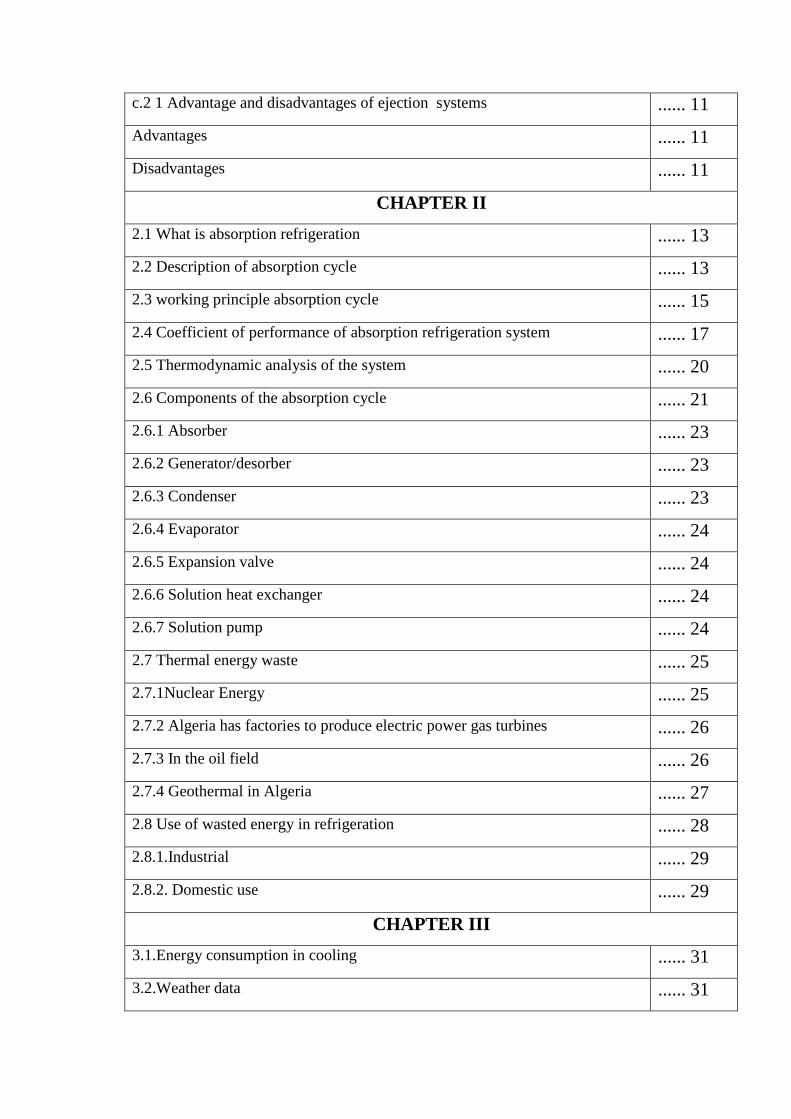
c.2 1 Advantage and disadvantages of ejection systems ...... 11
Advantages ...... 11
Disadvantages ...... 11
CHAPTER II
2.1 What is absorption refrigeration ...... 13
2.2 Description of absorption cycle ...... 13
2.3 working principle absorption cycle ...... 15
2.4 Coefficient of performance of absorption refrigeration system ...... 17
2.5 Thermodynamic analysis of the system ...... 20
2.6 Components of the absorption cycle ...... 21
2.6.1 Absorber ...... 23
2.6.2 Generator/desorber ...... 23
2.6.3 Condenser ...... 23
2.6.4 Evaporator ...... 24
2.6.5 Expansion valve ...... 24
2.6.6 Solution heat exchanger ...... 24
2.6.7 Solution pump ...... 24
2.7 Thermal energy waste ...... 25
2.7.1Nuclear Energy ...... 25
2.7.2 Algeria has factories to produce electric power gas turbines ...... 26
2.7.3 In the oil field ...... 26
2.7.4 Geothermal in Algeria ...... 27
2.8 Use of wasted energy in refrigeration ...... 28
2.8.1.Industrial ...... 29
2.8.2. Domestic use ...... 29
CHAPTER III
3.1.Energy consumption in cooling ...... 31
3.2.Weather data ...... 31

3.3.Building data ...... 34
3.4.DESCRIPTION OF THE TRNSYS ...... 37
3.5.Coefficient of performance ...... 40
Conclusion General ...... 41
Recommendation ...... 41
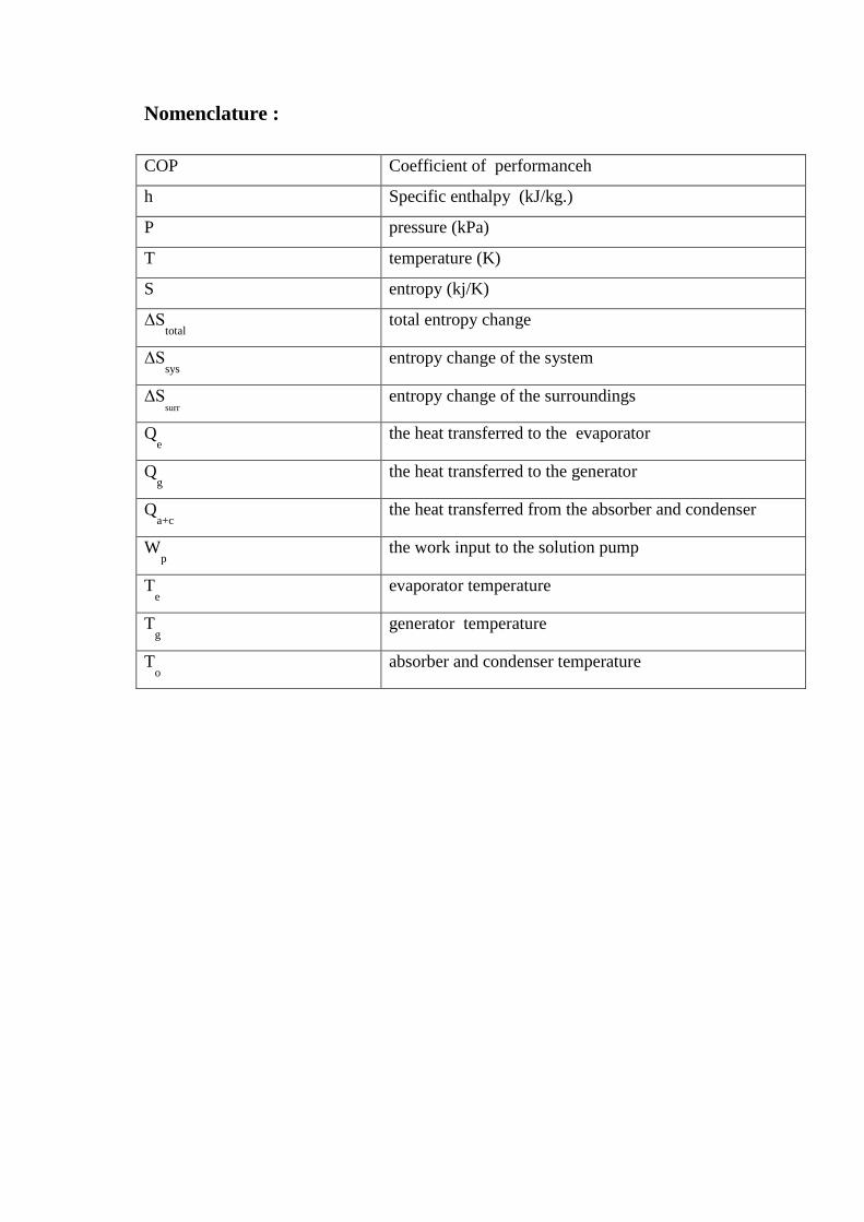
Nomenclature :
COP Coefficient of performanceh
h Specific enthalpy (kJ/kg.)
P pressure (kPa)
T temperature (K)
S entropy (kj/K)
ΔStotal
total entropy change
ΔSsys
entropy change of the system
ΔSsurr
entropy change of the surroundings
Qe the heat transferred to the evaporator
Qg the heat transferred to the generator
Qa+c
the heat transferred from the absorber and condenser
Wp
the work input to the solution pump
Te evaporator temperature
Tg generator temperature
To absorber and condenser temperature
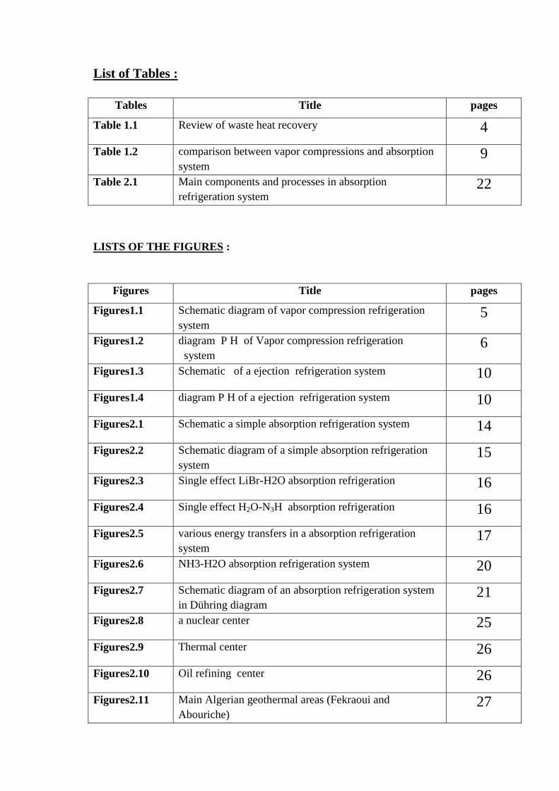
List of Tables :
Tables Title pages
Table 1.1 Review of waste heat recovery 4
Table 1.2 comparison between vapor compressions and absorption
system 9
Table 2.1 Main components and processes in absorption
refrigeration system 22
LISTS OF THE FIGURES :
Figures Title pages
Figures1.1 Schematic diagram of vapor compression refrigeration
system 5
Figures1.2 diagram P H of Vapor compression refrigeration
system 6
Figures1.3 Schematic of a ejection refrigeration system 10
Figures1.4 diagram P H of a ejection refrigeration system 10
Figures2.1 Schematic a simple absorption refrigeration system 14
Figures2.2 Schematic diagram of a simple absorption refrigeration
system 15
Figures2.3 Single effect LiBr-H2O absorption refrigeration 16
Figures2.4 Single effect H2O-N3H absorption refrigeration 16
Figures2.5 various energy transfers in a absorption refrigeration
system 17
Figures2.6 NH3-H2O absorption refrigeration system 20
Figures2.7 Schematic diagram of an absorption refrigeration system
in Dühring diagram 21
Figures2.8 a nuclear center 25
Figures2.9 Thermal center 26
Figures2.10 Oil refining center 26
Figures2.11 Main Algerian geothermal areas (Fekraoui and
Abouriche) 27
Figures2.12 Temperatures in the Earth 28
Figures2.13 Schematic diagram of a simple absorption refrigeration
system Connected to the heat exchanger 28
Figures2.14 Schematic of a simple absorption refrigeration system
Connected to the electricity production center 29
Figures3.1 Electricity production by source (2012) 31
Figures3.2 Monthly average variation of temperature during one year 32
Figures3.3 Daily average variation of temperature during one year 32
Figures3.4 Duration of sunshine and Astronomical duration of the
day during one year 33
Figures3.5 Diffuse and global radiation during one year 33
Figures3.6 operative room temperature of building during one year 34
Figures3.7 Air temperature °C of building during one year 35
Figures3.8 Heating (Q heat) and cooling (Q cool) demand of
building during one year 36
Figures3.9 TRNSYS SIMULATION STUDIO 37
Figures3.10 SYSTEME DESCRPTION 38
Figures3.11 Flowchart of absorption air-conditioning project 39
Fig 3.12 Coefficient of performance
40

Dedication
To my whole Family « Benzeghmane »
To my parents
To my wife and children
I dedicate this work
BOURAHLA BENZEGHMANE
Dedication
my whole family « kat »
To my parents
To my brothers and sisters
dedicate this work
KAT MOHAMED ALI

Acknowledgements
First of all, our thanks go to Allah the Almighty who gave us the
power to complete this work.
We would like to express our full gratitude to our
Supervisor,
Mr. Derghouth Zohir for his guidance, help, and
Encouragement
and academic support.
Also, we would like to express sincere thanks and appreciation to
the members of the jury for reading and evaluating
our work
and also great thanks to the Faculty of applied sciences
(Mechanical Engineering/ Energetic ) which embraced us
Finally, we are very thankful to all who helped us in conducting our
work.
GENERAL INTRODUCTION
1
GENERAL INTRODUCTION :
In Algeria, 60% of buildings consume energy in daily different fields such as refrigerators,
air conditioners and all what makes human comfortable and cannot dispense of using them in
nowadays life specially in South Algeria where the weather is very hot . 90% from the
electrical energy comes from the thermal energy installed specially in south Algeria [1].
Recently, the petrol is in decreasing, Algeria will suffer from this decreasing in the coming
generations because all its economics depend on this non-renewable energy so that it requires
compensating this problem with the renewable energies that do not harm the environment and
last forever such as solar energy, eolian, hydraulics, geothermal….
And to preserve this energy we should economize it the maximum and use it wisely without
wasting it to find solutions to this tough problem.
To solve this problem we should work on the waste energies by refrigeration absorption to
lead us to the decrease of the global warming and we should pay attention to Industrial
thermal waste and the domestic application with the usage of the hot water of the area that is
related to as a recourse of the temperature for alimentation of the boiler.
In this dissertation the work is divided into three chapters
the first one is dealt with the review of the refrigerating system and mentioning some of the
researches that are related to this field (absorption refrigerating cycle), whether the second
chapter is concerned with the studied system and defining it and giving some illustrations
about the thesis.
Finally in the third chapter we will discuss the results that is lead by the whole dissertation .

CHAPTER I REVIEW
3
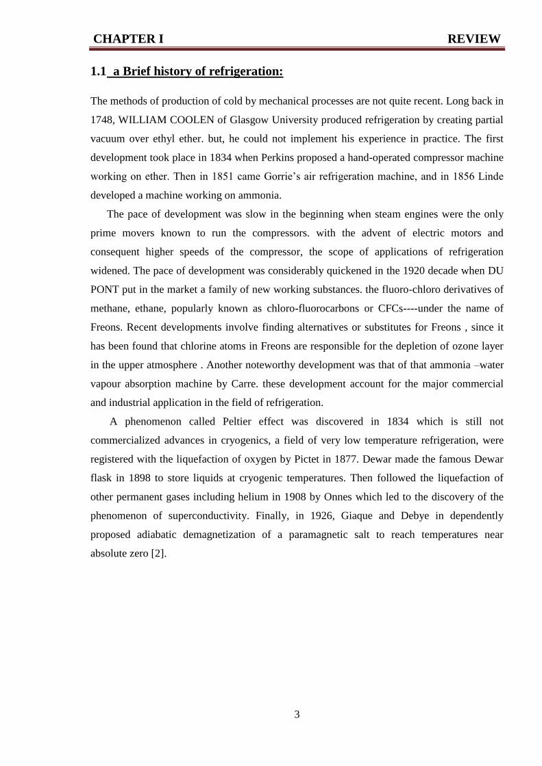
1.1 a Brief history of refrigeration:
The methods of production of cold by mechanical processes are not quite recent. Long back in
1748, WILLIAM COOLEN of Glasgow University produced refrigeration by creating partial
vacuum over ethyl ether. but, he could not implement his experience in practice. The first
development took place in 1834 when Perkins proposed a hand-operated compressor machine
working on ether. Then in 1851 came Gorrie’s air refrigeration machine, and in 1856 Linde
developed a machine working on ammonia.
The pace of development was slow in the beginning when steam engines were the only
prime movers known to run the compressors. with the advent of electric motors and
consequent higher speeds of the compressor, the scope of applications of refrigeration
widened. The pace of development was considerably quickened in the 1920 decade when DU
PONT put in the market a family of new working substances. the fluoro-chloro derivatives of
methane, ethane, popularly known as chloro-fluorocarbons or CFCs----under the name of
Freons. Recent developments involve finding alternatives or substitutes for Freons , since it
has been found that chlorine atoms in Freons are responsible for the depletion of ozone layer
in the upper atmosphere . Another noteworthy development was that of that ammonia –water
vapour absorption machine by Carre. these development account for the major commercial
and industrial application in the field of refrigeration.
A phenomenon called Peltier effect was discovered in 1834 which is still not
commercialized advances in cryogenics, a field of very low temperature refrigeration, were
registered with the liquefaction of oxygen by Pictet in 1877. Dewar made the famous Dewar
flask in 1898 to store liquids at cryogenic temperatures. Then followed the liquefaction of
other permanent gases including helium in 1908 by Onnes which led to the discovery of the
phenomenon of superconductivity. Finally, in 1926, Giaque and Debye in dependently
proposed adiabatic demagnetization of a paramagnetic salt to reach temperatures near
absolute zero [2].
CHAPTER I REVIEW
4
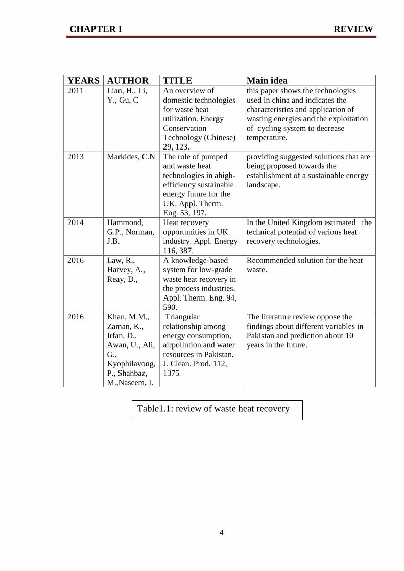
YEARS AUTHOR TITLE Main idea 2011 Lian, H., Li,
Y., Gu, C
An overview of
domestic technologies
for waste heat
utilization. Energy
Conservation
Technology (Chinese)
29, 123.
this paper shows the technologies
used in china and indicates the
characteristics and application of
wasting energies and the exploitation
of cycling system to decrease
temperature.
2013 Markides, C.N The role of pumped
and waste heat
technologies in ahigh-
efficiency sustainable
energy future for the
UK. Appl. Therm.
Eng. 53, 197.
providing suggested solutions that are
being proposed towards the
establishment of a sustainable energy
landscape.
2014 Hammond,
G.P., Norman,
J.B.
Heat recovery
opportunities in UK
industry. Appl. Energy
116, 387.
In the United Kingdom estimated the
technical potential of various heat
recovery technologies.
2016 Law, R.,
Harvey, A.,
Reay, D.,
A knowledge-based
system for low-grade
waste heat recovery in
the process industries.
Appl. Therm. Eng. 94,
590.
Recommended solution for the heat
waste.
2016 Khan, M.M.,
Zaman, K.,
Irfan, D.,
Awan, U., Ali,
G.,
Kyophilavong,
P., Shahbaz,
M.,Naseem, I.
Triangular
relationship among
energy consumption,
airpollution and water
resources in Pakistan.
J. Clean. Prod. 112,
1375.
The literature review oppose the
findings about different variables in
Pakistan and prediction about 10
years in the future.
Table1.1: review of waste heat recovery
CHAPTER I REVIEW
5
1.2 Classification of refrigeration systems :
Two main classes of refrigeration systems can be distinguished; those are Mechanical energy
to operate, the mechano-refrigeration systems and which Consume mainly thermal energy, the
thermo-refrigerating systems
1.2.1 Mechanical refrigeration systems:
among them, two families stand out:
a / Liquefiable vapor compression systems,
b/ Using gas cycles systems
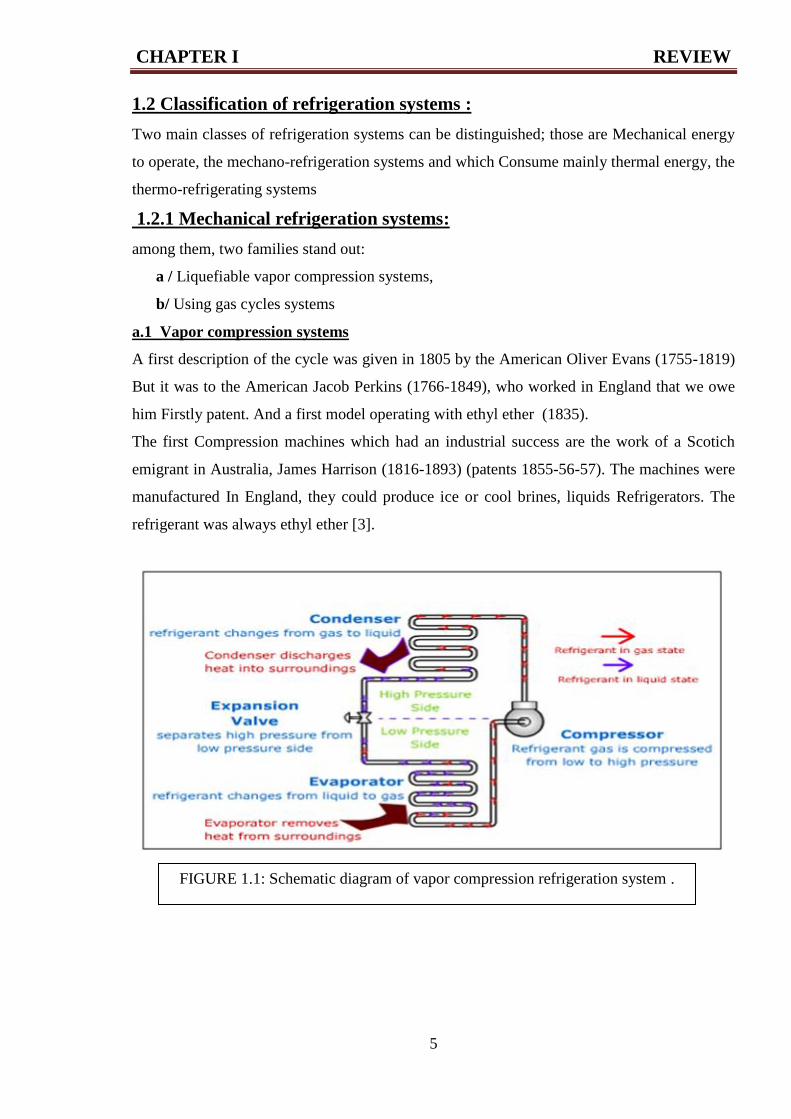
a.1 Vapor compression systems
A first description of the cycle was given in 1805 by the American Oliver Evans (1755-1819)
But it was to the American Jacob Perkins (1766-1849), who worked in England that we owe
him Firstly patent. And a first model operating with ethyl ether (1835).
The first Compression machines which had an industrial success are the work of a Scotich
emigrant in Australia, James Harrison (1816-1893) (patents 1855-56-57). The machines were
manufactured In England, they could produce ice or cool brines, liquids Refrigerators. The
refrigerant was always ethyl ether [3].
FIGURE 1.1: Schematic diagram of vapor compression refrigeration system .
CHAPTER I REVIEW
6
a.2 Advantage and disadvantages of vapour compression
Advantage:
1. It has smaller size for given capacity of refrigeration.
2. It has less running cost.
3. It can be employed over a large range of temperatures .
4. The coefficient of performance is quite high.
Disadvantages:
1. The initial cost is high .
2. The prevention of leakage of refrigerant is the major problem in vapour compression
system.
3. Many systems still use HCFC refrigerants, which contribute to depletion of ozone layer.
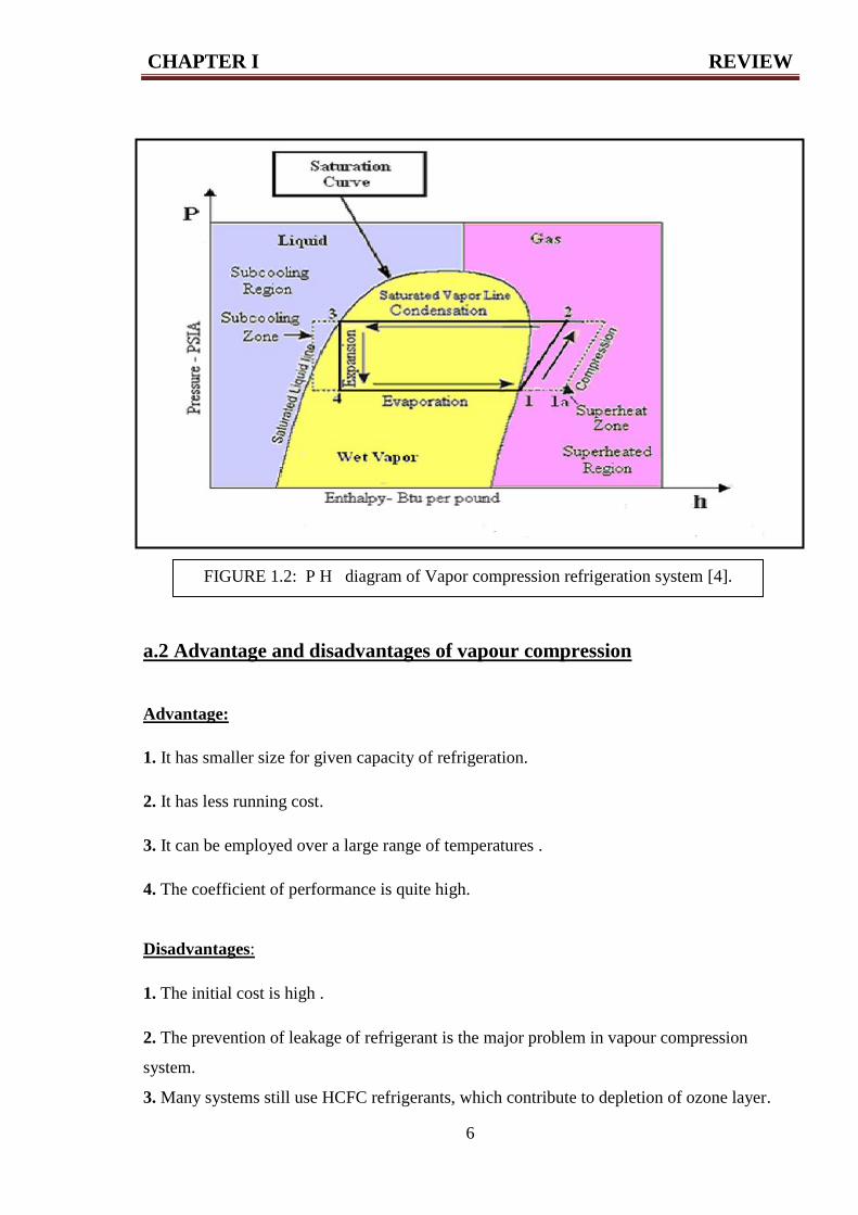
FIGURE 1.2: P H diagram of Vapor compression refrigeration system [4].
CHAPTER I REVIEW
7
a.3 Coefficient of performance :
COP = Q eva / w com
b - Using gas cycles systems
Here the active fluid does not change state during the refrigeration cycle but remains gaseous.
When it is compressed, the gas heats up, then it is cooled under pressure to the temperature
then it is relaxed, which results in a lowering of its temperature.
The first machine "outdoors" is due to the American John Gorrie (1803-1855) to cool the
brine at -7 ° C (patents 1850-51). Inspired by the air of Pastor Robert Stirling (1837) the Scot
Alexander Kirk (1830-1892) directed a closed cycle machine that regularly produces, for
about ten years.
Since 1864 a temperature of -13 °C. In this technique we can cite the contributions of the
German Franz Windhausen (1829-1904), the American Leicester Allen (1832-1912) and the
French Paul Giffard (1837-1897) [3].
The development of these systems was less than that of the steam compression machines
because their efficiency is reduced in the ordinary field of refrigeration, freezing and air
conditioning. However, they are at the origin of most cryogenic cycles for liquefaction of
gases and production of low temperatures.
1.2.2 Thermo-refrigeration systems:
One can distinguish among these refrigerating systems consuming thermal energy:
a/ Absorption systems.
b/ bsorption and thermo-chemical systems.
c/ Ejection systems.
a.1 Absorption systems:
Although their importance is much smaller than compression systems, they are currently the
only thermo-refrigeration systems that are developing. Here the circulation of the refrigerant
is not due to a mechanical compressor but to the circulation by pump of an absorbent liquid
whose content, of refrigerant absorbed, depends on the temperature and the pressure.

CHAPTER I REVIEW
8
Mechanical work required is very small, the system, on the other hand, consumes heat, the
father of these systems is the French Ferdinand Carré (1824-1900) who patented in 1859 the
first continuous absorption machine using the refrigerant: ammonia - absorbent water.
These machines were almost immediately operational. Their thermodynamic study did not
start until 1913 with the German man Edmund Altenkirch and was continued during the first
half of the 20th century. We should also mention the work of the Italian Guido Maïuri on
these machines and those two people the Swedes von Platen and Munters on the absorption-
diffusion cycle for absorption refrigerators without a pump (1920).
In the 1940s, the lithium water-bromide absorption machine was introduced in the United
States, where water was the refrigerant; This adaptation of the Carre cycle Is widely used in
air conditioning.
Discontinuous absorption systems, although they appear very early, do not develop the idea
(devices to cool the jars of water of Edmond Carre - 1866).
a.2 Advantage and disadvantages of absorption systems
Advantage
1. No electricity required.
2. No chance of leakage.
3. High system reliability, very few failures.
4. waste heat can be used.
5. system not effected by variation of loads.
Disadvantages:
1. Low cop.
2. Higher cost initially.
3. Need to be installed perfectly horizontally .
CHAPTER I REVIEW
9
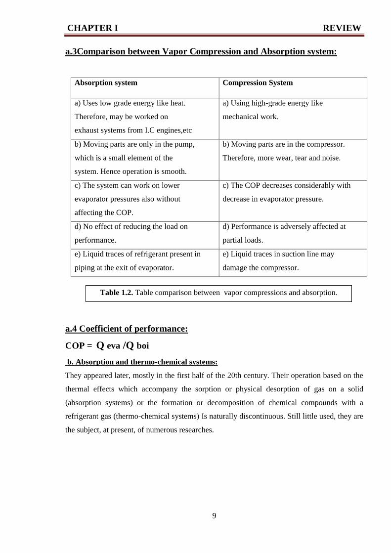
a.3Comparison between Vapor Compression and Absorption system:
Absorption system Compression System
a) Uses low grade energy like heat.
Therefore, may be worked on
exhaust systems from I.C engines,etc
a) Using high-grade energy like
mechanical work.
b) Moving parts are only in the pump,
which is a small element of the
system. Hence operation is smooth.
b) Moving parts are in the compressor.
Therefore, more wear, tear and noise.
c) The system can work on lower
evaporator pressures also without
affecting the COP.
c) The COP decreases considerably with
decrease in evaporator pressure.
d) No effect of reducing the load on
performance.
d) Performance is adversely affected at
partial loads.
e) Liquid traces of refrigerant present in
piping at the exit of evaporator.
e) Liquid traces in suction line may
damage the compressor.
a.4 Coefficient of performance:
COP = Q eva /Q boi
b. Absorption and thermo-chemical systems:
They appeared later, mostly in the first half of the 20th century. Their operation based on the
thermal effects which accompany the sorption or physical desorption of gas on a solid
(absorption systems) or the formation or decomposition of chemical compounds with a
refrigerant gas (thermo-chemical systems) Is naturally discontinuous. Still little used, they are
the subject, at present, of numerous researches.
Table 1.2. Table comparison between vapor compressions and absorption.
system
CHAPTER I REVIEW
10
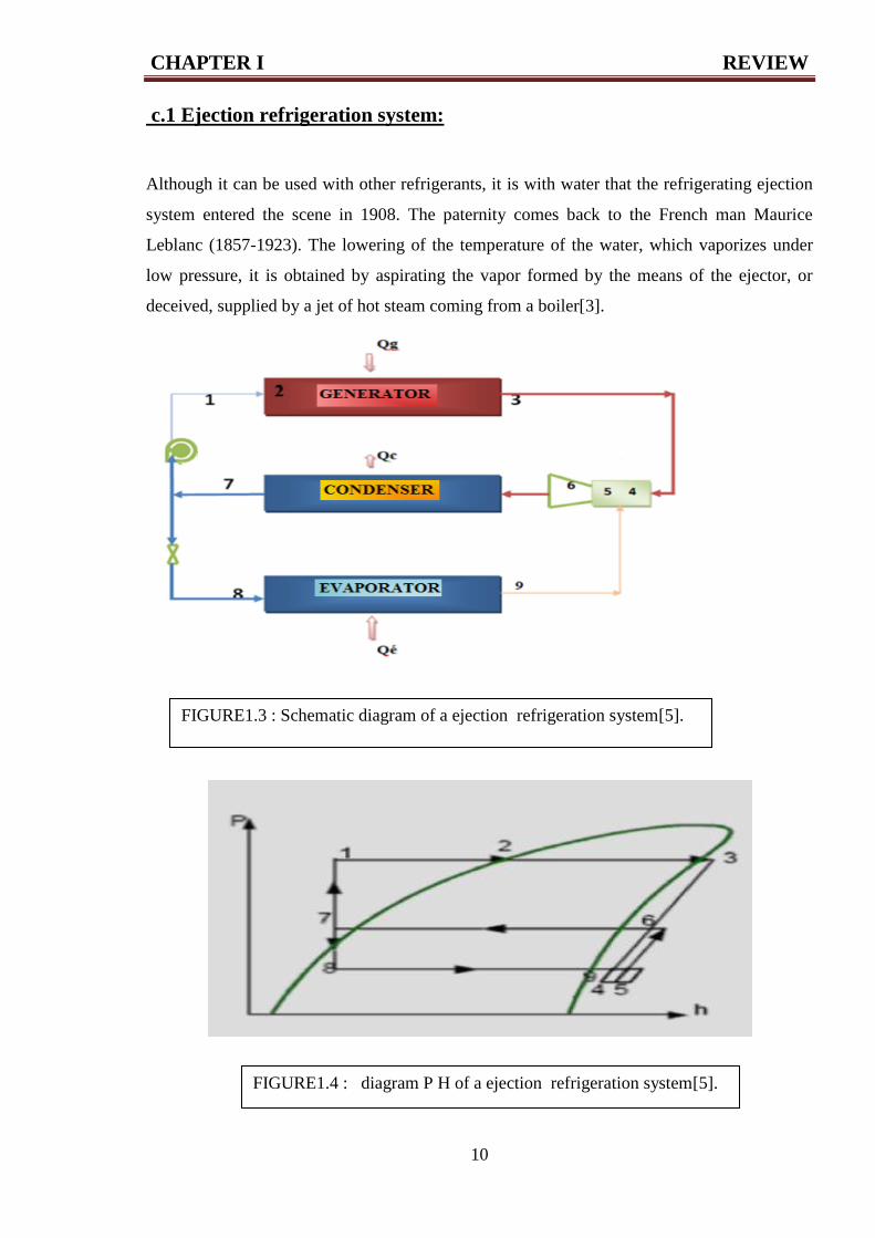
c.1 Ejection refrigeration system:
Although it can be used with other refrigerants, it is with water that the refrigerating ejection
system entered the scene in 1908. The paternity comes back to the French man Maurice
Leblanc (1857-1923). The lowering of the temperature of the water, which vaporizes under
low pressure, it is obtained by aspirating the vapor formed by the means of the ejector, or
deceived, supplied by a jet of hot steam coming from a boiler[3].
FIGURE1.3 : Schematic diagram of a ejection refrigeration system[5].
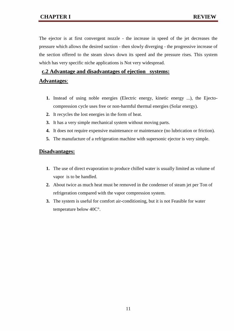
FIGURE1.4 : diagram P H of a ejection refrigeration system[5].
CHAPTER I REVIEW
11
The ejector is at first convergent nozzle - the increase in speed of the jet decreases the
pressure which allows the desired suction - then slowly diverging - the progressive increase of
the section offered to the steam slows down its speed and the pressure rises. This system
which has very specific niche applications is Not very widespread.
c.2 Advantage and disadvantages of ejection systems:
Advantages:
1. Instead of using noble energies (Electric energy, kinetic energy ...), the Ejecto-
compression cycle uses free or non-harmful thermal energies (Solar energy).
2. It recycles the lost energies in the form of heat.
3. It has a very simple mechanical system without moving parts.
4. It does not require expensive maintenance or maintenance (no lubrication or friction).
5. The manufacture of a refrigeration machine with supersonic ejector is very simple.
Disadvantages:
1. The use of direct evaporation to produce chilled water is usually limited as volume of
vapor is to be handled.
2. About twice as much heat must be removed in the condenser of steam jet per Ton of
refrigeration compared with the vapor compression system.
3. The system is useful for comfort air-conditioning, but it is not Feasible for water
temperature below 40C°.

CHAPTER II APSORPTION REFRIGERATION SYSTEM
13
2.1 What is absorption refrigeration?
Absorption refrigeration is another method of refrigeration, which instead of mechanical work
of the compressor utilizes locally available heat sources. Absorption is a chemical process in
which molecules of the refrigerant enter a bulk phase of a transport medium.
Absorption is not to be confused with adsorption, which means binding of refrigerant’s
molecules on the surface of a highly porous solid medium (adsorbent) — not within its
volume.
The absorption refrigeration systems are much more complex than vapor compression
systems, thus they occupy more space and are more expensive
Absorption is economically attractive only if there is a source of inexpensive thermal
energy available — the unit cost of thermal energy is low relative to electricity (and is
predicted remain low in the future).
The heat source could be either natural or artificial. The natural energy sources include
renewables such as solar energy or geothermal energy. The artificial heat source is typically
waste heat of some industrial process (e.g. in power plants or production facilities) or exhaust
gases from the engines. The most attractive sources are at the temperature (100c°_200c°) [6].
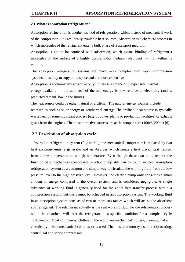
2.2 Description of absorption cycle:
absorption refrigeration system (Figure 2.1), the mechanical compressor is replaced by two
heat exchange units, a generator and an absorber, which create a heat driven heat transfer
from a low temperature to a high temperature. Even though these two units replace the
function of a mechanical compressor, electric pump still can be found in most absorption
refrigeration system as a common and simple way to circulate the working fluid from the low
pressure level to the high pressure level. However, the electric pump only consumes a small
amount of energy compared to the overall system, and is considered negligible. A single
substance of working fluid is generally used for the entire heat transfer process within a
compression system, but this cannot be achieved in an absorption system. The working fluid
in an absorption system consists of two or more substances which will act as the absorbent
and refrigerant. The refrigerant actually is the real working fluid for the refrigeration process
while the absorbent will treat the refrigerant to a specific condition for a complete cycle
continuation. Most commercial chillers in the world are mechanical chillers, meaning that an
electrically-driven mechanical compressor is used. The most common types are reciprocating,
centrifugal and screw compressors.
CHAPTER II APSORPTION REFRIGERATION SYSTEM
14
The absorption refrigeration cycle has recently attracted much research attention because of
the possibility of using waste thermal energy or renewable energies as the power source, thus
reducing the demand for electricity supply [7].
Absorption cycles are used in applications where one or more of the exchanges of heat with
the surrounding is a useful product, for example refrigeration, air conditioning and heat
pumping.
The two great advantages of the absorption cycles compared to other cycles with similar
production.
• No large, rotating mechanical equipment is required .
• Any source of heat can be used, including low temperature sources.
FIGURE 2.1: Schematic A simple absorption refrigeration system.
CHAPTER II APSORPTION REFRIGERATION SYSTEM
15
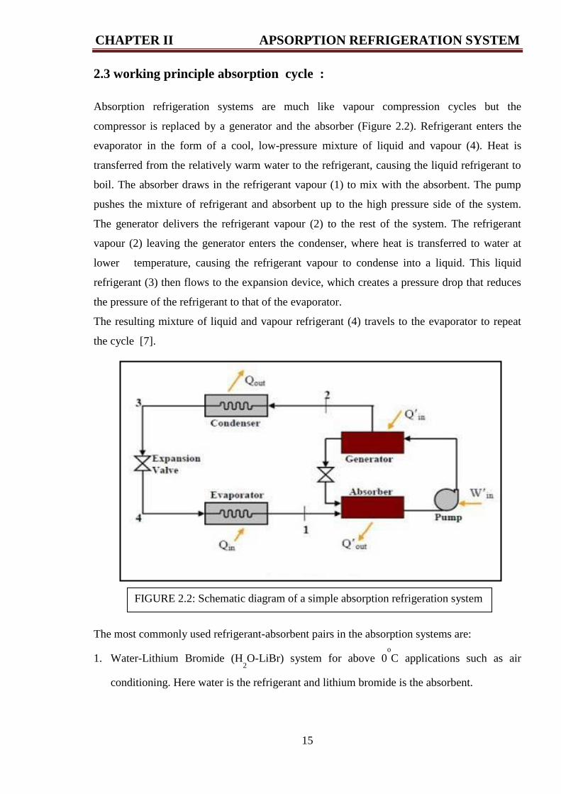
2.3 working principle absorption cycle :
Absorption refrigeration systems are much like vapour compression cycles but the
compressor is replaced by a generator and the absorber (Figure 2.2). Refrigerant enters the
evaporator in the form of a cool, low-pressure mixture of liquid and vapour (4). Heat is
transferred from the relatively warm water to the refrigerant, causing the liquid refrigerant to
boil. The absorber draws in the refrigerant vapour (1) to mix with the absorbent. The pump
pushes the mixture of refrigerant and absorbent up to the high pressure side of the system.
The generator delivers the refrigerant vapour (2) to the rest of the system. The refrigerant
vapour (2) leaving the generator enters the condenser, where heat is transferred to water at
lower temperature, causing the refrigerant vapour to condense into a liquid. This liquid
refrigerant (3) then flows to the expansion device, which creates a pressure drop that reduces
the pressure of the refrigerant to that of the evaporator.
The resulting mixture of liquid and vapour refrigerant (4) travels to the evaporator to repeat
the cycle [7].
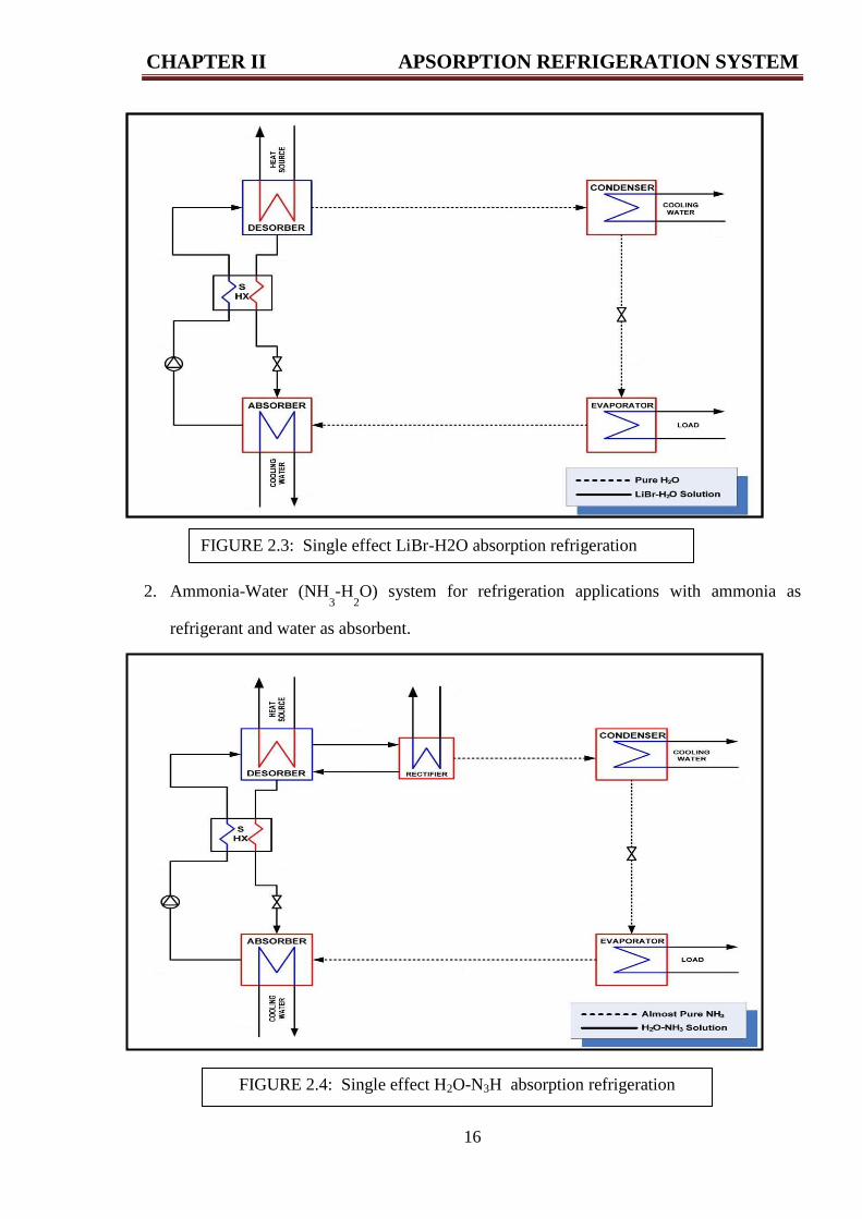
The most commonly used refrigerant-absorbent pairs in the absorption systems are:
1. Water-Lithium Bromide (H2O-LiBr) system for above 0
o
C applications such as air
conditioning. Here water is the refrigerant and lithium bromide is the absorbent.
FIGURE 2.2: Schematic diagram of a simple absorption refrigeration system
CHAPTER II APSORPTION REFRIGERATION SYSTEM
16
2. Ammonia-Water (NH3-H
2O) system for refrigeration applications with ammonia as
refrigerant and water as absorbent.
FIGURE 2.3: Single effect LiBr-H2O absorption refrigeration
system
FIGURE 2.4: Single effect H2O-N3H absorption refrigeration
system
CHAPTER II APSORPTION REFRIGERATION SYSTEM
17
3. Of late efforts are being made to develop other refrigerant-absorbent systems using both
natural and synthetic refrigerants to overcome some of the limitations of (H2O-LiBr) and
(NH3-H
2 O) systems.
4. Currently, large water-lithium bromide (H2O-LiBr) systems are extensively used in air
conditioning applications, whereas large ammonia-water (NH3-H
2O) systems are used in
refrigeration applications .
5. used in a pumpless form in small domestic refrigerators [8].
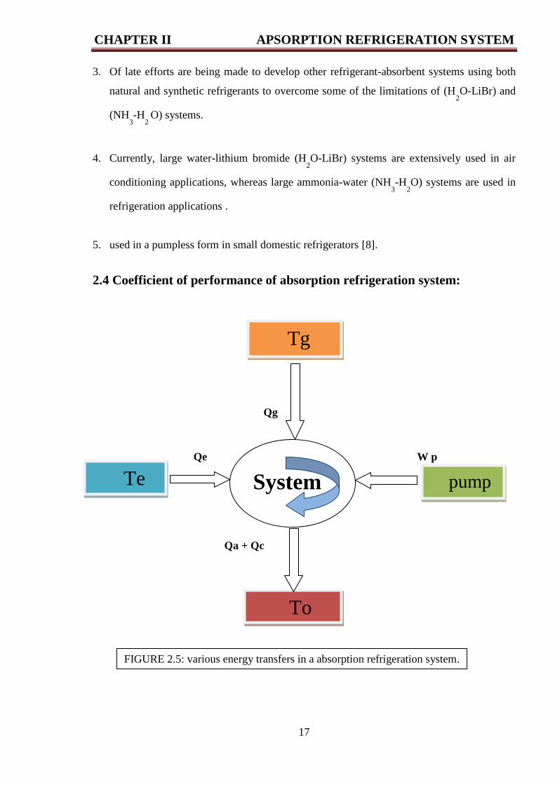
2.4 Coefficient of performance of absorption refrigeration system:
Qg
Qe W p
Qa + Qc
System pump
Tg
Te
To
FIGURE 2.5: various energy transfers in a absorption refrigeration system.
CHAPTER II APSORPTION REFRIGERATION SYSTEM
18
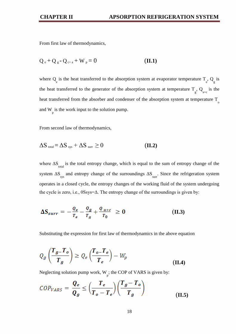
From first law of thermodynamics,
Q e + Q g - Q c+ a + W p = 0 (II.1)
where Qe
is the heat transferred to the absorption system at evaporator temperature Te, Q
g is
the heat transferred to the generator of the absorption system at temperature Tg, Q
a+c is the
heat transferred from the absorber and condenser of the absorption system at temperature To
and Wp
is the work input to the solution pump.
From second law of thermodynamics,
ΔS total = ΔS sys + ΔS surr ≥ 0 (II.2)
where ΔStotal
is the total entropy change, which is equal to the sum of entropy change of the
system ΔSsys
and entropy change of the surroundings ΔSsurr
. Since the refrigeration system
operates in a closed cycle, the entropy changes of the working fluid of the system undergoing
the cycle is zero, i.e., 0Ssys=Δ. The entropy change of the surroundings is given by:
(II.3)
Substituting the expression for first law of thermodynamics in the above equation
(II.4)
Neglecting solution pump work, Wp; the COP of VARS is given by:
(II.5)
CHAPTER II APSORPTION REFRIGERATION SYSTEM
19
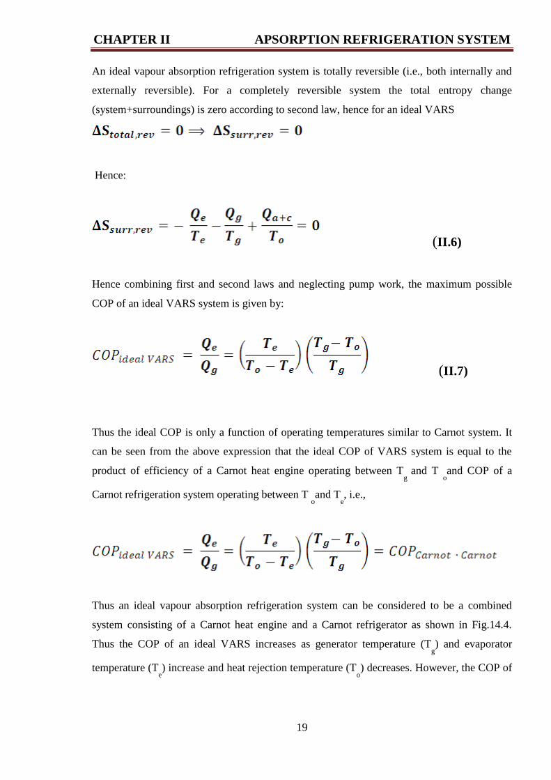
An ideal vapour absorption refrigeration system is totally reversible (i.e., both internally and
externally reversible). For a completely reversible system the total entropy change
(system+surroundings) is zero according to second law, hence for an ideal VARS
Hence:
(II.6)
Hence combining first and second laws and neglecting pump work, the maximum possible
COP of an ideal VARS system is given by:
(II.7)
Thus the ideal COP is only a function of operating temperatures similar to Carnot system. It
can be seen from the above expression that the ideal COP of VARS system is equal to the
product of efficiency of a Carnot heat engine operating between Tg
and T oand COP of a
Carnot refrigeration system operating between T oand T
e, i.e.,
Thus an ideal vapour absorption refrigeration system can be considered to be a combined
system consisting of a Carnot heat engine and a Carnot refrigerator as shown in Fig.14.4.
Thus the COP of an ideal VARS increases as generator temperature (Tg) and evaporator
temperature (Te) increase and heat rejection temperature (T
o) decreases. However, the COP of
CHAPTER II APSORPTION REFRIGERATION SYSTEM
20
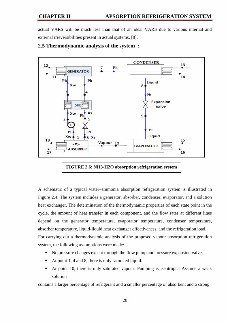
FIGURE 2.6: NH3-H2O absorption refrigeration system
actual VARS will be much less than that of an ideal VARS due to various internal and
external irreversibilities present in actual systems. [8].
2.5 Thermodynamic analysis of the system :
A schematic of a typical water–ammonia absorption refrigeration system is illustrated in
Figure 2.4. The system includes a generator, absorber, condenser, evaporator, and a solution
heat exchanger. The determination of the thermodynamic properties of each state point in the
cycle, the amount of heat transfer in each component, and the flow rates at different lines
depend on the generator temperature, evaporator temperature, condenser temperature,
absorber temperature, liquid-liquid heat exchanger effectiveness, and the refrigeration load.
For carrying out a thermodynamic analysis of the proposed vapour absorption refrigeration
system, the following assumptions were made:
No pressure changes except through the flow pump and pressure expansion valve.
At point 1, 4 and 8, there is only saturated liquid.
At point 10, there is only saturated vapour. Pumping is isentropic. Assume a weak
solution
contains a larger percentage of refrigerant and a smaller percentage of absorbent and a strong
CHAPTER II APSORPTION REFRIGERATION SYSTEM
21
solution contains a larger percentage of absorbent and a smaller percentage of refrigerant. The
percentages of the weak solution at state 1, 2 and 3 and the percentages of the strong solution
at state 4, 5 and 6 will remain same. The temperatures at thermodynamic states 11, 12, 13, 14,
15,16, 17 and 18 are the external circuit for water which is used to input heat for the
components of the system shown in Figure 2.4.
This system has two pressure limits; one is a high-pressure limit and the other is the
low-pressure limit.
P1 = P6 = P9 = P10 = Low pressure.
P2 = P3 = P4 = P5 = P7 = P8 = High pressure. [7]
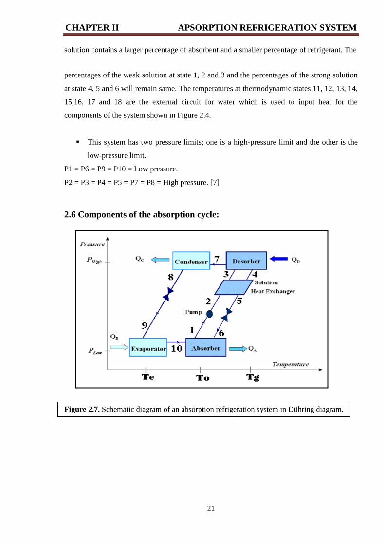
2.6 Components of the absorption cycle:
Figure 2.7. Schematic diagram of an absorption refrigeration system in Dühring diagram.
CHAPTER II APSORPTION REFRIGERATION SYSTEM
22
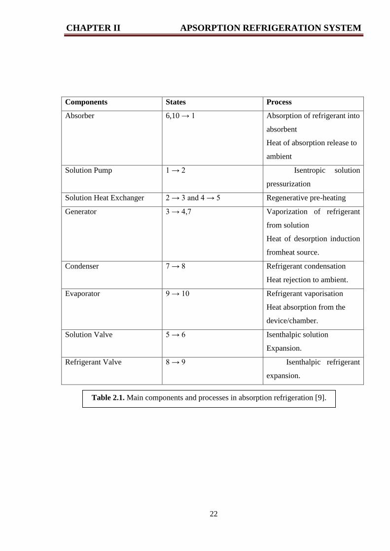
Table 2.1. Main components and processes in absorption refrigeration [9].
Components States Process
Absorber 6,10 → 1 Absorption of refrigerant into
absorbent
Heat of absorption release to
ambient
Solution Pump 1 → 2 Isentropic solution
pressurization
Solution Heat Exchanger 2 → 3 and 4 → 5 Regenerative pre-heating
Generator 3 → 4,7 Vaporization of refrigerant
from solution
Heat of desorption induction
fromheat source.
Condenser 7 → 8 Refrigerant condensation
Heat rejection to ambient.
Evaporator 9 → 10 Refrigerant vaporisation
Heat absorption from the
device/chamber.
Solution Valve 5 → 6 Isenthalpic solution
Expansion.
Refrigerant Valve 8 → 9 Isenthalpic refrigerant
expansion.
CHAPTER II APSORPTION REFRIGERATION SYSTEM
23
2.6.1 Absorber:
The absorber is a chamber where the absorbent and the refrigerant vapour are mixed together.
It is equipped with a heat rejection system, i.e. bundles of tubes as in the condenser, and
operates under a low pressure level which corresponds to the evaporator temperature. The
absorption process can only occur if the absorber is at a sensible low temperature level, hence
the heat rejection system needs to be attached. The mixing process of the absorbent and the
refrigerant vapour generate latent heat of condensation and raise the solution temperature.
Simultaneous with the developmental processing of
latent heat, heat transfer with cooling water will then lower the absorber temperature and,
together with the solution temperature, creates a well-blended solution that will be ready for
the next cycle. A lower absorber temperature means more refrigerating capacity due to a
higher refrigerant’s flow rate from the evaporator.
2.6.2 Generator/ desorber :
The desorber operates under high pressure which is controlled either by the temperature of the
incoming heat to the desorber or the condensation temperature required by the cooling water
entering the condenser. The desorption process generates vapour and extracts the refrigerant
from the working fluid by the addition of the external heat from the heat source; it could be
desorption of water out of a lithium bromide-water solution or ammonia out of a water-
ammonia solution. The refrigerant vapour travels to the condenser while the liquid absorbent
is gravitationally settled at the bottom of the desorber; the pressure difference between the
desorber and the absorber then causes it to flow out to the absorber through an expansion
valve.
2.6.3 Condenser:
A liquid state of a refrigerant is a must in order for the refrigeration process to run. Hence, the
vapour phase of a refrigerant from the desorber is altered to a liquid by the condenser. The
condensing process of a high pressure refrigerant vapour is done by rejecting the vapour’s
latent heat to the sink, following a regular heat balance formulation.
CHAPTER II APSORPTION REFRIGERATION SYSTEM
24
2.6.4 Evaporator:
The temperature of evaporation regulates the lower pressure level of the absorption system. a
low pressure of two phase refrigerant from the flow restrictor continues to evaporate due to
the addition of latent heat from the refrigeration environment. a complete evaporation process
will convert the two phase refrigerant into vapour.
2.6.5 Expansion valve:
An expansion valve is a component that reduces the pressure and splits the two different
pressure levels. In a simple model of a single effect absorption refrigeration system, the
pressure change is assumed only to occur at the expansion valve and the solution pump. There
is no heat added or removed from the working fluid at the expansion valve. The enthalpy of
the working fluid remains the same on both sides. The pressure change process between the
two end points of the expansion valve, while there is no mass flow change and the process is
assumed as an adiabatic process, can change the volume if the fluid generates a small amount
of steam phase via flashing.
2.6.6 Solution heat exchanger:
A solution heat exchanger is a heat exchange unit with the purpose of pre-heating the solution
before it enters the desorber and removing unwanted heat from the absorbent. The heat
exchange process within the solution heat exchanger reduces the amount of heat required
from the heat source in the desorber and also reduces the quantity of heat to be rejected by the
heat sink (cooling water) in the absorber as well.
2.6.7 Solution pump:
Although the main distinction between compression and absorption refrigeration is the
replacement of the mechanically driven system by a heat driven system, the presence of a
mechanically driven component is still needed in an absorption system. A solution pump will
mainly circulate and lift the solution from the lower pressure level side to the higher pressure
level side of the system. To maintain this pressure difference, a centrifugal type pump is
preferable. Assuming the solution is an uncompressible liquid, in other words the specific
CHAPTER II APSORPTION REFRIGERATION SYSTEM
25
volume of the liquid (ν) will not change during the pumping process, the power requirement
to lift the solution with mass flow from pressure level P1 to P2 2.2 [10]
2.7 Thermal energy waste
There is high thermal energy in many fields in the world in hot ground water or produced
from the centers of production of electricity or nuclear reactors or in engines, but why not
exploit it?
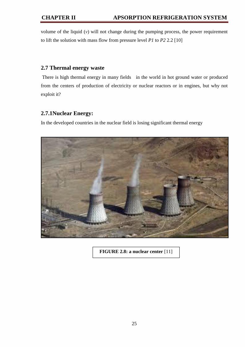
2.7.1Nuclear Energy:
In the developed countries in the nuclear field is losing significant thermal energy
FIGURE 2.8: a nuclear center [11]
CHAPTER II APSORPTION REFRIGERATION SYSTEM
26
FIGURE 2.9: thermal center [12]
2.7.2 Algeria has factories to produce electric power gas turbines:
Most of Algeria is electricity output is from thermal centers.
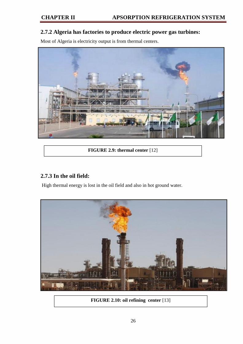
2.7.3 In the oil field:
High thermal energy is lost in the oil field and also in hot ground water.
FIGURE 2.10: oil refining center [13]
CHAPTER II APSORPTION REFRIGERATION SYSTEM
27
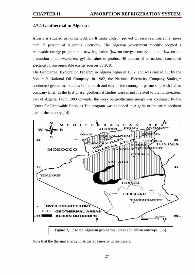
Figure 2,11: Main Algerian geothermal areas and albian outcrops [15].
2.7.4 Geothermal in Algeria :
Algeria is situated in northern Africa It ranks 16th in proved oil reserves. Currently, more
than 98 percent of Algeria’s electricity. The Algerian government recently adopted a
renewable energy program and new legislation (law on energy conservation and law on the
promotion of renewable energy) that aims to produce 40 percent of its national consumed
electricity from renewable energy sources by 2030.
The Geothermal Exploration Program in Algeria began in 1967, and was carried out by the
Sonatrach National Oil Company. In 1982, the National Electricity Company Sonlegaz
conducted geothermal studies in the north and east of the country in partnership with Italian
company Enel. In the first phase, geothermal studies were mainly related to the north-eastern
part of Algeria. From 1983 onwards, the work on geothermal energy was continued by the
Center for Renewable Energies The program was extended in Algeria to the entire northern
part of the country [14].
Note that the thermal energy in Algeria is mostly in the desert.
CHAPTER II APSORPTION REFRIGERATION SYSTEM
28
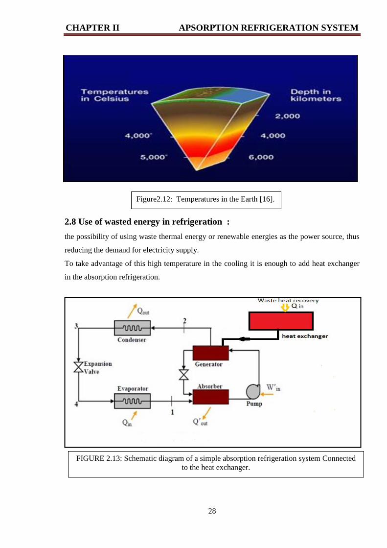
FIGURE 2.13: Schematic diagram of a simple absorption refrigeration system Connected
to the heat exchanger.
2.8 Use of wasted energy in refrigeration :
the possibility of using waste thermal energy or renewable energies as the power source, thus
reducing the demand for electricity supply.
To take advantage of this high temperature in the cooling it is enough to add heat exchanger
in the absorption refrigeration.
Figure2.12: Temperatures in the Earth [16].
CHAPTER II APSORPTION REFRIGERATION SYSTEM
29
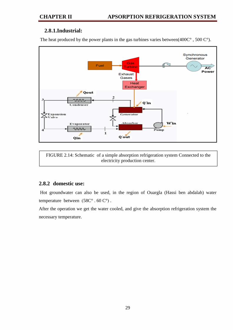
2.8 .1.Industrial:
The heat produced by the power plants in the gas turbines varies between(400C° , 500 C°).
2.8.2 domestic use:
Hot groundwater can also be used, in the region of Ouargla (Hassi ben abdalah) water
temperature between )58C° . 60 C°( .
After the operation we get the water cooled, and give the absorption refrigeration system the
necessary temperature.
FIGURE 2.14: Schematic of a simple absorption refrigeration system Connected to the
electricity production center.

CHAPTER III RESULTS AND DISCUSS
31
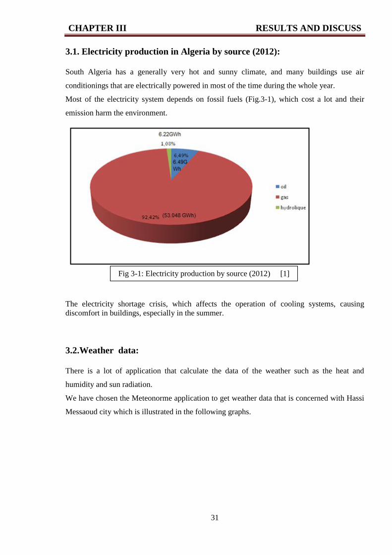
3.1. Electricity production in Algeria by source (2012):
South Algeria has a generally very hot and sunny climate, and many buildings use air
conditionings that are electrically powered in most of the time during the whole year.
Most of the electricity system depends on fossil fuels (Fig.3-1), which cost a lot and their
emission harm the environment.
The electricity shortage crisis, which affects the operation of cooling systems, causing
discomfort in buildings, especially in the summer.
3.2.Weather data:
There is a lot of application that calculate the data of the weather such as the heat and
humidity and sun radiation.
We have chosen the Meteonorme application to get weather data that is concerned with Hassi
Messaoud city which is illustrated in the following graphs.
Fig 3-1: Electricity production by source (2012) [1]
CHAPTER III RESULTS AND DISCUSS
32
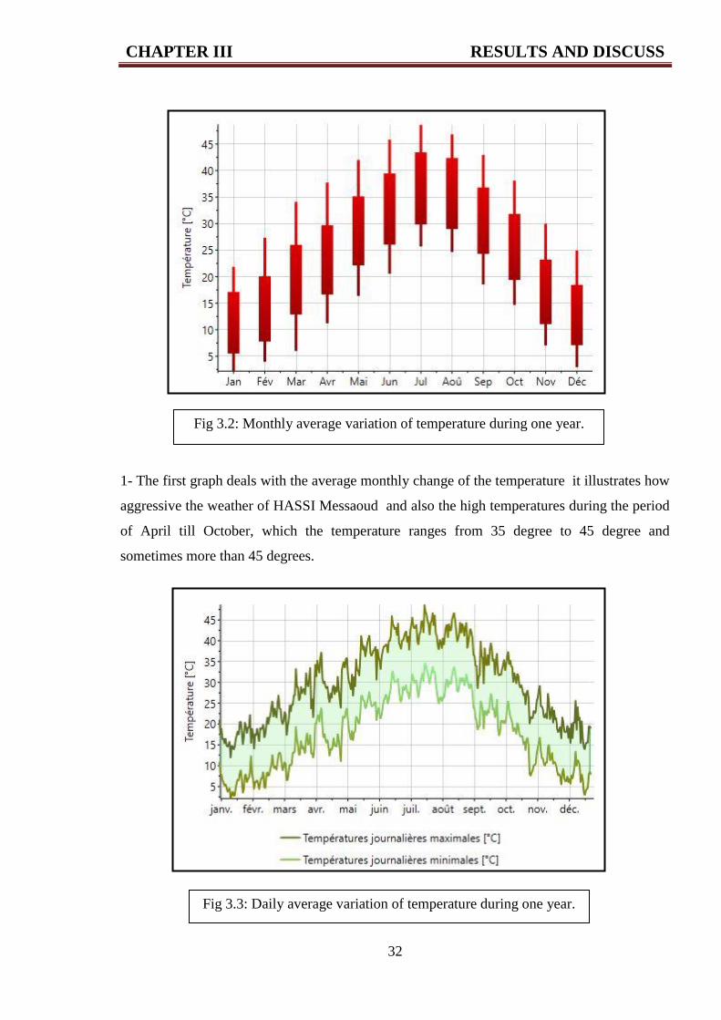
1- The first graph deals with the average monthly change of the temperature it illustrates how
aggressive the weather of HASSI Messaoud and also the high temperatures during the period
of April till October, which the temperature ranges from 35 degree to 45 degree and
sometimes more than 45 degrees.
Fig 3.2: Monthly average variation of temperature during one year.
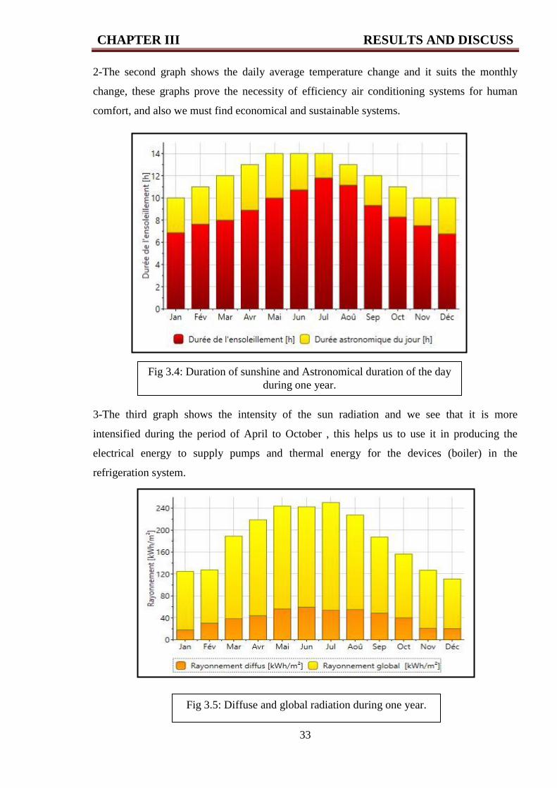
Fig 3.3: Daily average variation of temperature during one year.
CHAPTER III RESULTS AND DISCUSS
33
2-The second graph shows the daily average temperature change and it suits the monthly
change, these graphs prove the necessity of efficiency air conditioning systems for human
comfort, and also we must find economical and sustainable systems.
3-The third graph shows the intensity of the sun radiation and we see that it is more
intensified during the period of April to October , this helps us to use it in producing the
electrical energy to supply pumps and thermal energy for the devices (boiler) in the
refrigeration system.
Fig 3.4: Duration of sunshine and Astronomical duration of the day
during one year.
Fig 3.5: Diffuse and global radiation during one year.
CHAPTER III RESULTS AND DISCUSS
34
4- The fourth graph represents the sunniest periods which support the third graph we notice
that the period which the weather is sunny is the period that is mentioned before (between
April and October).
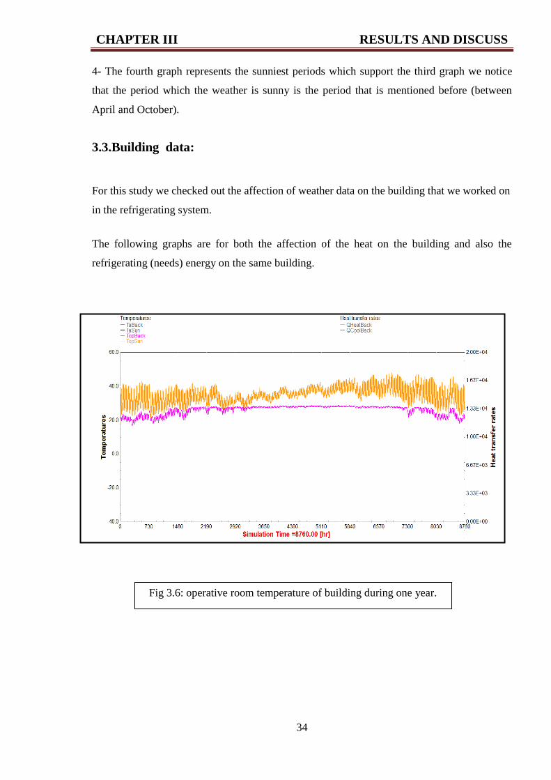
3.3.Building data:
For this study we checked out the affection of weather data on the building that we worked on
in the refrigerating system.
The following graphs are for both the affection of the heat on the building and also the
refrigerating (needs) energy on the same building.
Fig 3.6: operative room temperature of building during one year.
CHAPTER III RESULTS AND DISCUSS
35
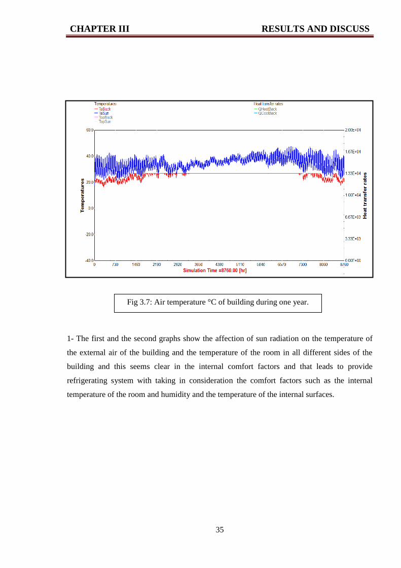
1- The first and the second graphs show the affection of sun radiation on the temperature of
the external air of the building and the temperature of the room in all different sides of the
building and this seems clear in the internal comfort factors and that leads to provide
refrigerating system with taking in consideration the comfort factors such as the internal
temperature of the room and humidity and the temperature of the internal surfaces.
Fig 3.7: Air temperature °C of building during one year.
CHAPTER III RESULTS AND DISCUSS
36
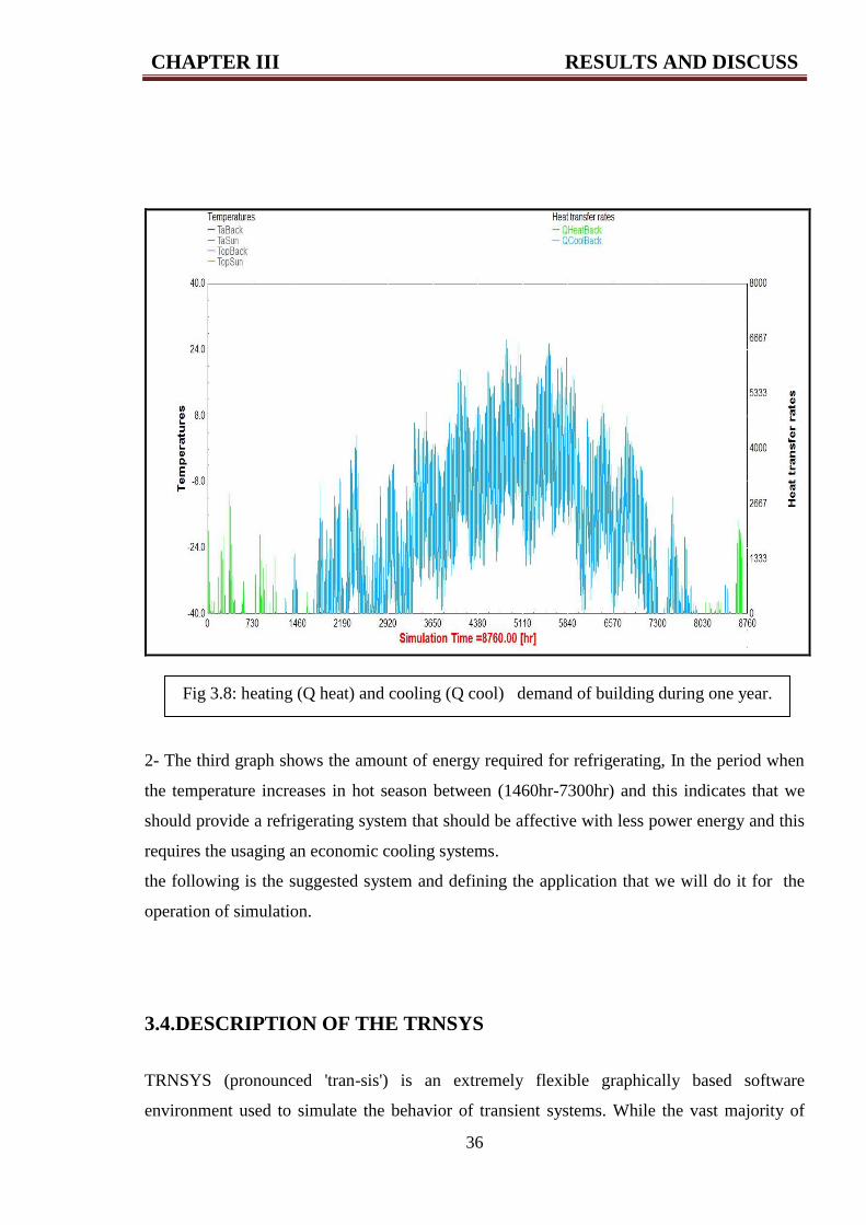
2- The third graph shows the amount of energy required for refrigerating, In the period when
the temperature increases in hot season between (1460hr-7300hr) and this indicates that we
should provide a refrigerating system that should be affective with less power energy and this
requires the usaging an economic cooling systems.
the following is the suggested system and defining the application that we will do it for the
operation of simulation.
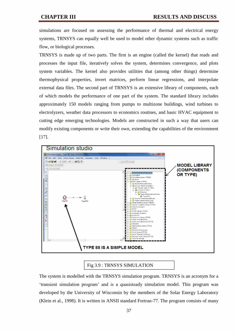
3.4.DESCRIPTION OF THE TRNSYS
TRNSYS (pronounced 'tran-sis') is an extremely flexible graphically based software
environment used to simulate the behavior of transient systems. While the vast majority of
Fig 3.8: heating (Q heat) and cooling (Q cool) demand of building during one year.
CHAPTER III RESULTS AND DISCUSS
37
simulations are focused on assessing the performance of thermal and electrical energy
systems, TRNSYS can equally well be used to model other dynamic systems such as traffic
flow, or biological processes.
TRNSYS is made up of two parts. The first is an engine (called the kernel) that reads and
processes the input file, iteratively solves the system, determines convergence, and plots
system variables. The kernel also provides utilities that (among other things) determine
thermophysical properties, invert matrices, perform linear regressions, and interpolate
external data files. The second part of TRNSYS is an extensive library of components, each
of which models the performance of one part of the system. The standard library includes
approximately 150 models ranging from pumps to multizone buildings, wind turbines to
electrolyzers, weather data processors to economics routines, and basic HVAC equipment to
cutting edge emerging technologies. Models are constructed in such a way that users can
modify existing components or write their own, extending the capabilities of the environment
[17].
The system is modelled with the TRNSYS simulation program. TRNSYS is an acronym for a
‘transient simulation program’ and is a quasisteady simulation model. This program was
developed by the University of Wisconsin by the members of the Solar Energy Laboratory
(Klein et al., 1998). It is written in ANSII standard Fortran-77. The program consists of many
Fig 3.9 : TRNSYS SIMULATION
STUDIO
CHAPTER III RESULTS AND DISCUSS
38
subroutines that model subsystem components. The mathematical models for the sub-system
components are given in terms of their ordinary differential or algebraic equations.
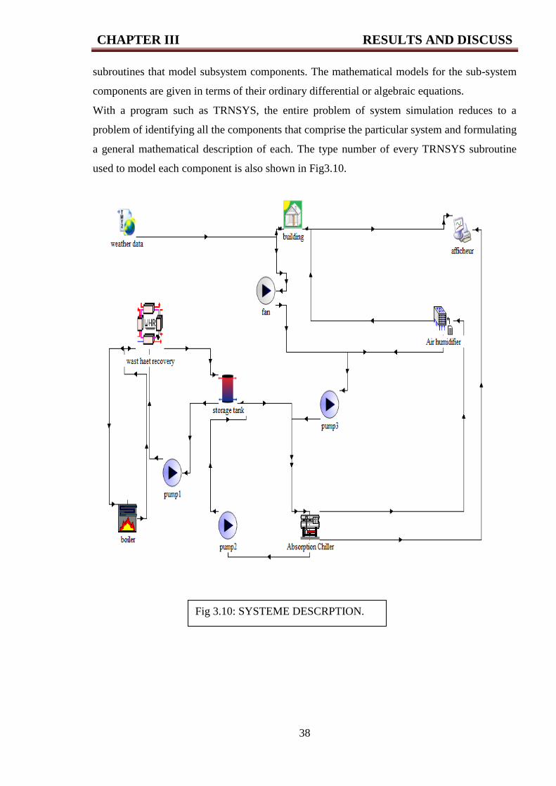
With a program such as TRNSYS, the entire problem of system simulation reduces to a
problem of identifying all the components that comprise the particular system and formulating
a general mathematical description of each. The type number of every TRNSYS subroutine
used to model each component is also shown in Fig3.10.
Fig 3.10: SYSTEME DESCRPTION.
CHAPTER III RESULTS AND DISCUSS
39
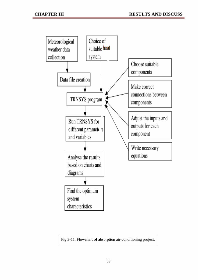
Fig 3-11. Flowchart of absorption air-conditioning project.
CHAPTER III RESULTS AND DISCUSS
40
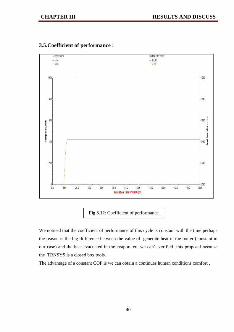
3.5.Coefficient of performance :
We noticed that the coefficient of performance of this cycle is constant with the time perhaps
the reason is the big difference between the value of generate heat in the boiler (constant in
our case) and the heat evacuated in the evaporated, we can’t verified this proposal because
the TRNSYS is a closed box tools.
The advantage of a constant COP is we can obtain a continues human conditions comfort .
Fig 3.12: Coefficient of performance.
GENERAL CONCLUSION AND RECOMMENDATIONS
41
General Conclusion:
The purpose of this work is to make a way to exploit the thermal energy resulting from the
turbine that exists in the industrial compound in Hassi Messaud city and also exploiting the
thermal energy of the local hot water for the operation of the absorption refrigerating using
the simulation application (TRNSYS) that through it we found precious pieces of information
in the field of refrigeration and several kinds of refrigeration cycles (absorption) and we knew
how to use and structure a certain refrigerating system in the application (TRNSYS) which is
considered an important tool in nowadays time(dynamic) used in a lot of institutes and
Scientific Research Centers especially in the renewable energy and building energy fields
It is also deduced the changes of temperature which requires an affective refrigeration and
heating system because the temperature that affects the factors of the human comfort and all
of that must be related to a good refrigerating system which doesn’t cost from the economic
side.
Recommendations:
1- Usage of other thermal energies of daily life like water, the flood, and the hot fountains
which is extracted from the ground.
2-Application and embodying the theoretical experiments practically just like the studied
example.
3- The exploitation of another waste industrial thermal energies with temperatures and it is
too many in the industrial life.
4- Use other thermal cycles to comparison.
5- Create a new component (new cycle of refrigeration) and add it to TRNSYS library.
42
REFERENCES
[1]http://www.iea.org/statistics/statisticssearch/report/?country=algeria&product=electricityan
dhet
[2] C-P-ARORA- refrigeration-air-conditioning- third-edition Y-2009
[3] Http: //www.iifiir.org . international institute of refrigeration
[4] A. BHATIA, B.E -Fundamentals of mechanical refrigeration systems-Y 2012
[5] BENTAMA. B: mémoire de magister , étude thermodynamique des mélanges des fluides
frigorigènes et leur utilisation dans les machines tritherme Université Mentouri Constantine.
[6] BOGUSŁAW BIAŁKO,BARTOSZ ZAJĄCZKOWSKI- refrigeration machines, system
applicationsY 2011.
[7] JANE UWERA-design of a cooling system for storage of agricultural products with
emphasis on irish potatoes Reports2013.
[8] me, iit kharagpur (REFRIGERATION AND AIR CONDITIONING( .version 1 _india
_2008 .
[9] HIFNI MUKHTAR ARIYADI -thermodynamic study on absorption refrigeration systems
using ammonia/ionic liquid - DOCTORAL THESIS July 2016.
[10] TESHA – absorption refrigeration system as an integrated condenser cooling unit in a
geothermal power plant-2009.
[11] Philippe Berthier (A bas le « renouvelable officiel » vive le nucléaire ! ) /5/10/2013.
[12] lematin dz .net Deux nouveaux gisements entrent en production à Hassi Messaoud.
[13] Le contre-choc pétrolier conduit l’Algérie à réduire ses dépenses En savoir plus sur
http://www.lemonde.fr/economie/article/2016/06/09/ .
[14] H. Saibi- Geothermal Resources in Algeria -april 2015
[15] Hakim Saibi, Renewable and Sustainable Energy Reviews Oct 20, 2015
[16] http://www.growingchristians.org/rfgc/genesis/transcripts/lesson1-3.
[17] http www.trnsys.com.