Embed Size (px)
Citation preview

Option Board
IEI-02 for
mega Drive-Line IIO
Technical Descriptionand Operating Instructions
BAUMÜLLER
E 5.00033.02Edition: July 2001

BAUMÜLLER
OPTION BOARD IEI-02 FOR DRIVE-LINE II
Technical Description and Operating Instructions
Edition: July 2001
Document no. 5.00033.02
This operation manual is intended as a complement to the technical description and the operation ma-nual of the apparatus.
BEFORE CARRYING OUT COMMISSIONING, CAREFULLY READ AND OBSERVE THE OPERATING INSTRUCTIONS
AND SAFETY INFORMATION
This document contains all the information necessary to correctly use the products it describes. It is in-tended for specially trained, technically qualified personnel who are well-versed in all warnings and com-missioning activities.
The equipment is manufactured using state-of-the-art technology and is safe in operation. It can safelybe installed and commissioned and functions without problems if the safety information is followed.
You may not carry out commissioning until it has been established that the machine into which this com-ponent is to be installed complies with the specifications of the EC machine guidelines.
This technical description/these operating instructions invalidate all previous descriptions of the corre-sponding product. Within the scope of further development of our products, Baumüller GmbH reservesthe right to change their technical data and handling.
Manufacturer and Baumüller Nürnberg GmbHSupplier’s Address: Ostendstr. 80
D-90482 Nürnberg Tel. ++49 (0)9 11/54 32 - 0 Fax ++49 (0)9 11/54 32 - 1 30
Copyright: These operating instructions or extracts from them may not be copied or dupli-cated without our permission.
Country of Origin: Germany
Date of Manufacture: Determined from the serial number on the equipment
Option Board IEI-02 for Drive-Line IIBaumüller Nürnber g GmbH 5.00033.02

2 Option Board IEI-02 for Drive-Line II5.00033.02 Baumüller Nürnber g GmbH
Table of Contents
TABLE OF CONTENTS
1 Safety Information ............................................................................................. 5
2 Technical Data ................................................................................................... 7
2.1 General ............................................................................................................................... 7
2.1.1 Using the IEI-02 for Position Acquisition ............................................................... 72.1.2 Using the IEI-02 as a Rapid Counter ..................................................................... 7
2.2 Technical Data of the Option Board .................................................................................... 8
3 Installation ........................................................................................................ 11
3.1 Pin Assignment ................................................................................................................. 11
3.2 LEDs ................................................................................................................................. 13
3.3 Accessories ....................................................................................................................... 14
4 Using the IEI-02 in the PROPROG wt II Project ............................................ 15
4.1 Libraries Under PROPROG wt II ....................................................................................... 15
4.2 Data Types for the IEI-02 .................................................................................................. 16
4.3 Declaring Variables ........................................................................................................... 18
4.4 Structure Assignment and Register Addresses ................................................................ 20
4.4.1 Structure Elements of IEI_READ_BMSTRUCT .................................................. 204.4.2 Structure Elements of IEI_WRITE_BMSTRUCT ................................................. 22
4.5 Configuring and Operating the IEI-02 ............................................................................... 23
4.5.1 The IEI-02 Trigger Signal .................................................................................... 234.5.2 IEI-02 COMMAND Register ................................................................................ 234.5.3 IEI-02 STATUS register ....................................................................................... 244.5.4 IEI-02 MODE Register ......................................................................................... 254.5.5 Procedure at Acquisition of Print Marks and Zero Tracks ................................... 25
4.6 Function Initialization of the IEI-02 via FB IEI02_INIT ....................................................... 28
5 Index ................................................................................................................. 31
Option Board IEI-02 for Drive-Line II IIIBaumüller Nürnber g GmbH 5.00033.02

Table of Contents
IV Option Board IEI-02 for Drive-Line II5.00033.02 Baumüller Nürnber g GmbH
Safety Information
1 SAFETY INFORMATION
General Information
These operating instructions contain all the information necessary for correct operation of the productsdescribed. The document is intended for specially trained, technically qualified personnel who are well-versed in all warnings and commissioning activities.
The equipment is manufactured using state-of-the-art technology and is safe in operation. It can safelybe installed and commissioned and functions without problems if the safety information in these opera-ting instructions is followed.
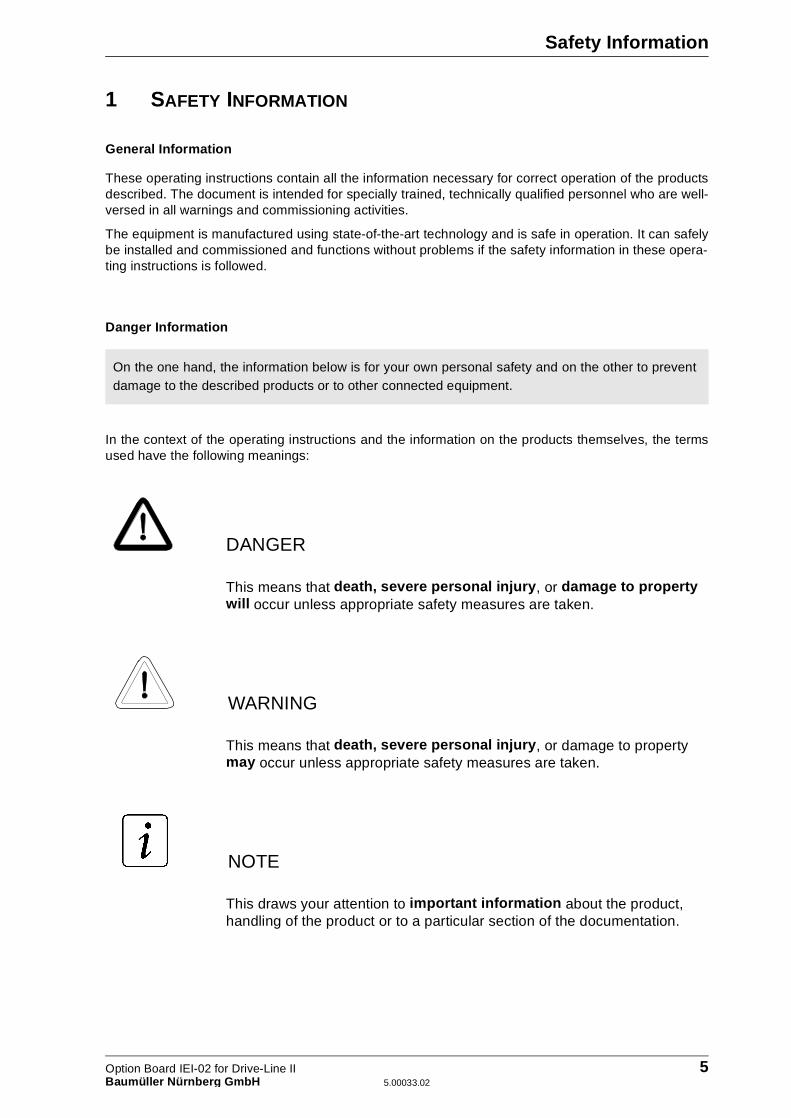
Danger Information
In the context of the operating instructions and the information on the products themselves, the termsused have the following meanings:
This means that death, severe personal injury , or damage to property will occur unless appropriate safety measures are taken.
This means that death, severe personal injury , or damage to property may occur unless appropriate safety measures are taken.
This draws your attention to important information about the product, handling of the product or to a particular section of the documentation.
On the one hand, the information below is for your own personal safety and on the other to preventdamage to the described products or to other connected equipment.
DANGER
WARNING
NOTE
Option Board IEI-02 for Drive-Line II 5Baumüller Nürnber g GmbH 5.00033.02
Safety Information
Qualified Personnel
In the context of the safety-specific information in this document or on the products themselves, qualifiedpersonnel are considered to be persons who are familiar with setting up, assembling, commissioning andoperating the product and who have qualifications appropriate to their activities:
� Trained or instructed or authorized to commission, ground and mark circuits and equipment in acor-dance with recognized safety standards.
� Trained or instructed in accordance with recognized safety standards in the care and use of appro-priate safety equipment.
Appropriate Use
You may only use the equipment/system for the purposes specified in the operating instructions and in conjunction with the third-party equipment and components recommended or authorized by BAUMÜLLER NÜRNBERG GmbH.
For safety reasons, you must not change or add components on/to the equipment/system.
The machine minder must report immediately any changes that occur which adversely affect the safety of the equipment/system.
WARNING
6 Option Board IEI-02 for Drive-Line II5.00033.02 Baumüller Nürnber g GmbH
Technical Data
2 TECHNICAL DATA
2.1 General
2.1.1 Using the IEI-02 for Position Acquisition
You can use the IEI-02 (Incremental Encoder Interface) as a counter module for position acquisition forpositioning and synchronization tasks.
The IEI-02 is an option board of the �mega Drive-Line II system with two counter channels. For positionacquisition, you can connect commercially available square-wave incremental encoders with differentresolutions. The IEI-02 counts the signal edges with a 4-MHz counter, which allows it to evaluate high-resolution encoders too.
The IEI-02 is initialized and it carries out evaluation in a PROPROG wt II program under IEC 61131-3.A function block from library IEI_DLII_20bd00 (or above) is available for initialization. LibraryREGISTER_DLII_20bd00 (or above) is available as an option for further functions like referenceable ab-solute positions, angles with print mark positions and the functions of a register controller.
This results in the following areas of application for position acquisition:
� as a real leading axle for cam disks
� for position acquisition for positioning maneouvres
� for position acquisition for web-cylinder register controllers
� for position acquisition for web-web register controllers
� for position acquisition for infeed tasks
� for format measurement
2.1.2 Using the IEI-02 as a Rapid Counter
As an alternative to position acquisition, you can configure the IEI-02 as a rapid counter for tracer si-gnals. The system can evaluate the 24 V tracer signal at up to 200 kHz. This means that you can carryout any counting procedures you like on 24 V industrial logic-based sensors. This yields the followingarea of application, for example:
� Copy counter
It is also possible to use the IEI-02 as a rapid counter in-parallel with application as position acquisitionvia the second counter.
Note that the system counts both edges of the tracer signal.
Option Board IEI-02 for Drive-Line II 7Baumüller Nürnber g GmbH 5.00033.02
Technical Data
2.2 Technical Data of the Option Board
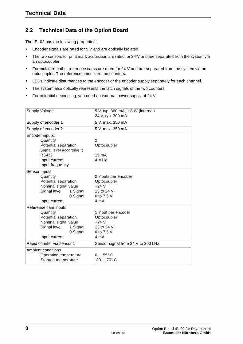
The IEI-02 has the following properties:
� Encoder signals are rated for 5 V and are optically isolated.
� The two sensors for print mark acquisition are rated for 24 V and are separated from the system via an optocoupler.
� For multiturn paths, reference cams are rated for 24 V and are separated from the system via an optocoupler. The reference cams zero the counters.
� LEDs indicate disturbances to the encoder or the encoder supply separately for each channel.
� The system also optically represents the latch signals of the two counters.
� For potential decoupling, you need an external power supply of 24 V.
Supply Voltage 5 V, typ. 360 mA, 1.8 W (internal)24 V, typ. 300 mA
Supply of encoder 1 5 V, max. 350 mA
Supply of encoder 2 5 V, max. 350 mA
Encoder inputs:QuantityPotential separationS igna l leve l according to R S422Input currentInput frequency
2Optocoupler
15 mA4 MHz
Sensor inputsQuantityPotential separationNominal signal valueSignal level 1 Signal
0 SignalInput current
2 inputs per encoderOptocoupler+24 V13 to 24 V0 to 7.5 V4 mA
Reference cam inputsQuantityPotential separationNominal signal valueSignal level 1 Signal
0 SignalInput current
1 input per encoderOptocoupler+24 V13 to 24 V0 to 7.5 V4 mA
Rapid counter via sensor 1 Sensor signal from 24 V to 200 kHz
Ambient conditionsOperating temperatureStorage temperature
0 ... 55° C-30 ... 70° C
8 Option Board IEI-02 for Drive-Line II5.00033.02 Baumüller Nürnber g GmbH
Technical Data
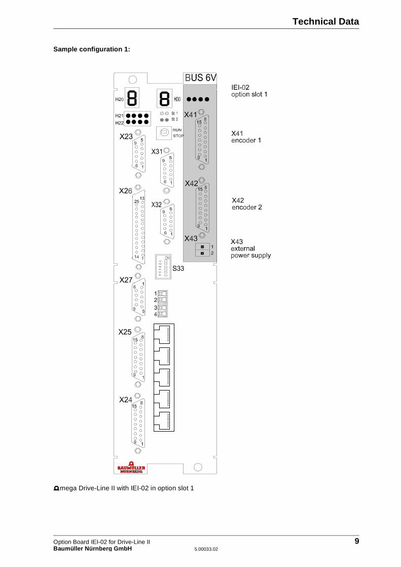
Sample configuration 1:
�mega Drive-Line II with IEI-02 in option slot 1
Option Board IEI-02 for Drive-Line II 9Baumüller Nürnber g GmbH 5.00033.02
Technical Data
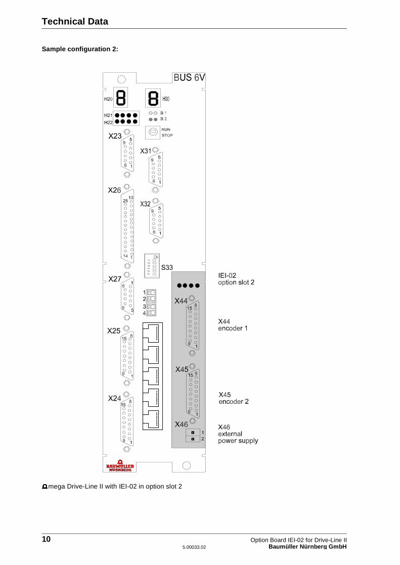
Sample configuration 2:
�mega Drive-Line II with IEI-02 in option slot 2
10 Option Board IEI-02 for Drive-Line II5.00033.02 Baumüller Nürnber g GmbH
Installation
3 INSTALLATION
3.1 Pin Assignment
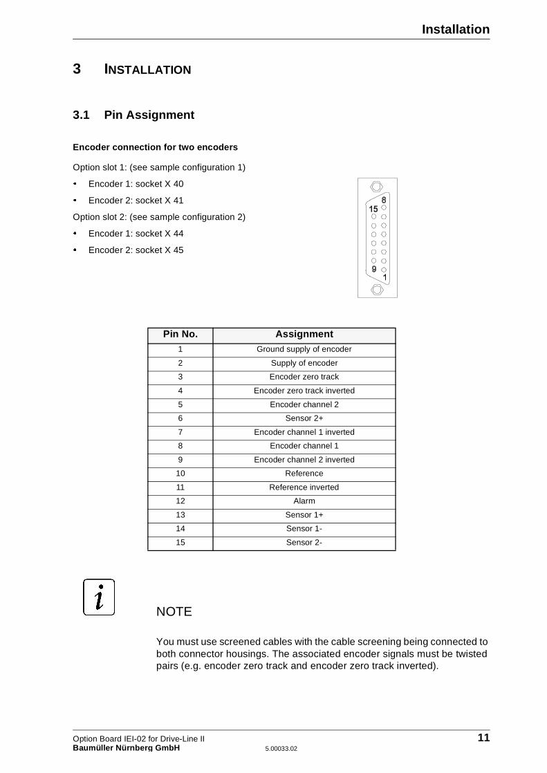
Encoder connection for two encoders
Option slot 1: (see sample configuration 1)
� Encoder 1: socket X 40
� Encoder 2: socket X 41
Option slot 2: (see sample configuration 2)
� Encoder 1: socket X 44
� Encoder 2: socket X 45
You must use screened cables with the cable screening being connected to both connector housings. The associated encoder signals must be twisted pairs (e.g. encoder zero track and encoder zero track inverted).
Pin No. Assignment1 Ground supply of encoder
2 Supply of encoder
3 Encoder zero track
4 Encoder zero track inverted
5 Encoder channel 2
6 Sensor 2+
7 Encoder channel 1 inverted
8 Encoder channel 1
9 Encoder channel 2 inverted
10 Reference
11 Reference inverted
12 Alarm
13 Sensor 1+
14 Sensor 1-
15 Sensor 2-
NOTE
Option Board IEI-02 for Drive-Line II 11Baumüller Nürnber g GmbH 5.00033.02
Installation
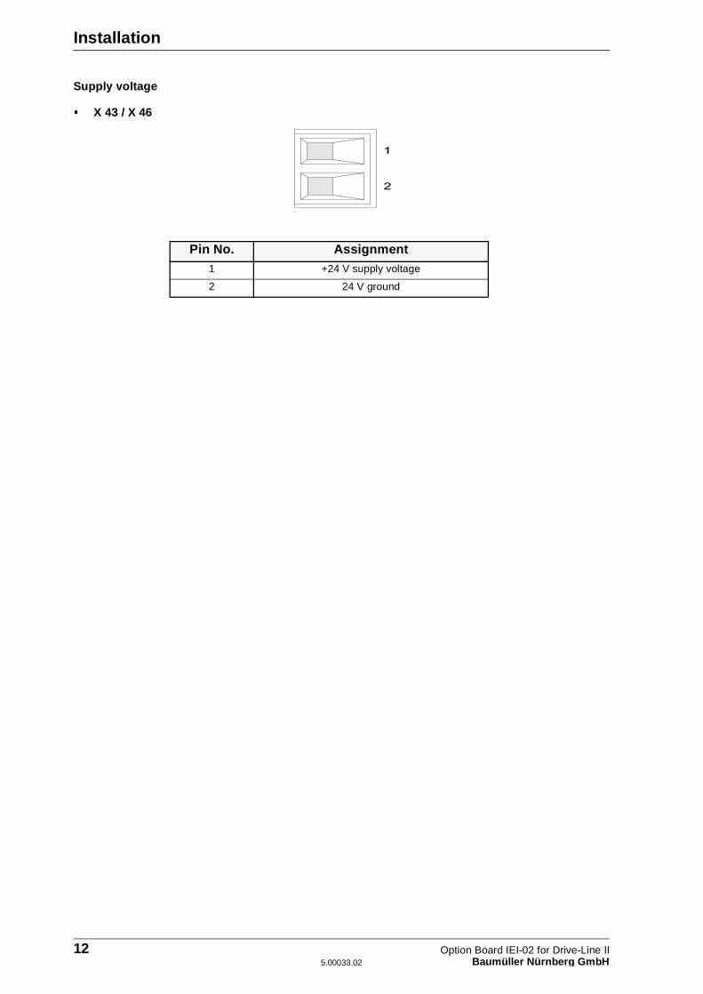
Supply voltage
� X 43 / X 46
Pin No. Assignment1 +24 V supply voltage
2 24 V ground
12 Option Board IEI-02 for Drive-Line II5.00033.02 Baumüller Nürnber g GmbH
Installation
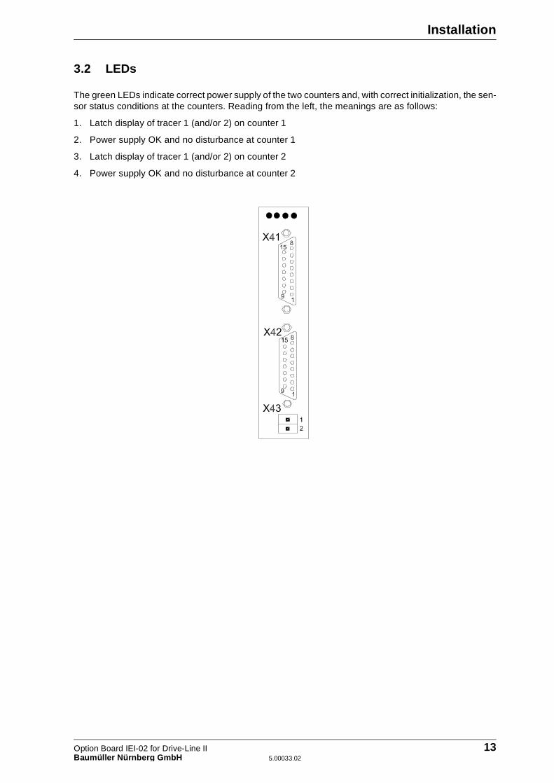
3.2 LEDs
The green LEDs indicate correct power supply of the two counters and, with correct initialization, the sen-sor status conditions at the counters. Reading from the left, the meanings are as follows:
1. Latch display of tracer 1 (and/or 2) on counter 1
2. Power supply OK and no disturbance at counter 1
3. Latch display of tracer 1 (and/or 2) on counter 2
4. Power supply OK and no disturbance at counter 2
Option Board IEI-02 for Drive-Line II 13Baumüller Nürnber g GmbH 5.00033.02

Installation
3.3 Accessories
2-pin connector for supply voltage.
14 Option Board IEI-02 for Drive-Line II5.00033.02 Baumüller Nürnber g GmbH

Using the IEI-02 in the PROPROG wt II Project
4 USING THE IEI-02 IN THE PROPROG WT II PROJECT
To be able to read the counter readings and to control references in the PROPROG wt II project, thesystem must access from the program the IEI-02's registers. To make these accesses easier, data typesare declared that mimic the IEI-02's register structure. See “Data Types for the IEI-02” on page 16.
The system uses these data types to declare variables that are assigned to the address of the optioninterface that is used. (See “Declaring Variables” on page 18.) In this way, the variables mimic the IEI-02's register structure (see structure elements in "Structure Assignment and Register Addresses"). Formore details about the option slots and option interfaces, refer to the �mega Drive-Line II technical de-scription.
After this, it is possible to use the structure elements of the declared variables to access the IEI-02's re-gister structure and to initialize the Incremental Encoder Interface in this way. Apart from this, the systemuses structure elements to enable references and to poll them (see "IEI-02 COMMAND register" and"IEI-02 STATUS register").
To correctly evaluate the option board, you must also configure a trigger signal (see "IEI-02 trigger si-gnal").
4.1 Libraries Under PROPROG wt II
You can set the functions of the IEI-02 using the function blocks (FBs) and register structures of thePROPROG wt II library from the following versions on.
You must insert the libraries in the project tree under libraries into the project.
The optional library of the register controller offers enhanced functions
� IEI_DLII_20bd00 (or above): Function block IEI02_INIT for setting the counter
� SYSTEM_DLII_20bd00 (or above): Function block OPT_INIT for interconnecting Trigger 1
� BM_TYPES_20bd00 (or above): Data type IEI_WRITE_BMSTRUCT for reading IEI-02 data type IEI_READ_BMSTRUCT for writing to the IEI-02
� REGISTER_DLII_20bd00 (or above): Function blocks of the register controller
Option Board IEI-02 for Drive-Line II 15Baumüller Nürnber g GmbH 5.00033.02
Using the IEI-02 in the PROPROG wt II Project
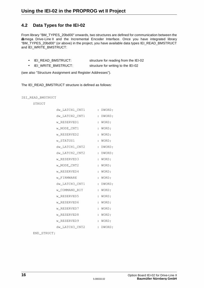
4.2 Data Types for the IEI-02
From library "BM_TYPES_20bd00" onwards, two structures are defined for communication between the�mega Drive-Line II and the Incremental Encoder Interface. Once you have integrated library"BM_TYPES_20bd00" (or above) in the project, you have available data types IEI_READ_BMSTRUCTand IEI_WRITE_BMSTRUCT:
(see also "Structure Assignment and Register Addresses").
The IEI_READ_BMSTRUCT structure is defined as follows:
IEI_READ_BMSTRUCT
STRUCT
dw_LATCH1_CNT1 : DWORD;
dw_LATCH2_CNT1 : DWORD;
w_RESERVED1 : WORD;
w_MODE_CNT1 : WORD;
w_RESERVED2 : WORD;
w_STATUS1 : WORD;
dw_LATCH1_CNT2 : DWORD;
dw_LATCH2_CNT2 : DWORD;
w_RESERVED3 : WORD;
w_MODE_CNT2 : WORD;
w_RESERVED4 : WORD;
w_FIRMWARE : WORD;
dw_LATCH3_CNT1 : DWORD;
w_COMMAND_BIT : WORD;
w_RESERVED5 : WORD;
w_RESERVED6 : WORD;
w_RESERVED7 : WORD;
w_RESERVED8 : WORD;
w_RESERVED9 : WORD;
dw_LATCH3_CNT2 : DWORD;
END_STRUCT;
� IEI_READ_BMSTRUCT: structure for reading from the IEI-02
� IEI_WRITE_BMSTRUCT: structure for writing to the IEI-02
16 Option Board IEI-02 for Drive-Line II5.00033.02 Baumüller Nürnber g GmbH
Using the IEI-02 in the PROPROG wt II Project
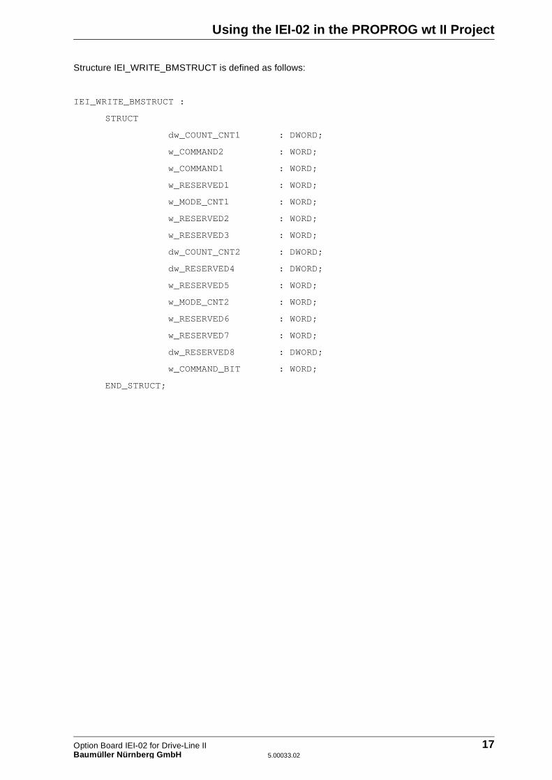
Structure IEI_WRITE_BMSTRUCT is defined as follows:
IEI_WRITE_BMSTRUCT :
STRUCT
dw_COUNT_CNT1 : DWORD;
w_COMMAND2 : WORD;
w_COMMAND1 : WORD;
w_RESERVED1 : WORD;
w_MODE_CNT1 : WORD;
w_RESERVED2 : WORD;
w_RESERVED3 : WORD;
dw_COUNT_CNT2 : DWORD;
dw_RESERVED4 : DWORD;
w_RESERVED5 : WORD;
w_MODE_CNT2 : WORD;
w_RESERVED6 : WORD;
w_RESERVED7 : WORD;
dw_RESERVED8 : DWORD;
w_COMMAND_BIT : WORD;
END_STRUCT;
Option Board IEI-02 for Drive-Line II 17Baumüller Nürnber g GmbH 5.00033.02

Using the IEI-02 in the PROPROG wt II Project
4.3 Declaring Variables
You declare two global variables of types global IEI_READ_BMSTRUCT and IEI_WRITE_BMSTRUCT.Using these variables and their structure elements (See “Structure Assignment and Register Addresses”on page 20.), you can access the Incremental Encoder Interface.
Apart from the marked registers of the IEI-02, it is only possible in the case of data types WORD and DWORD to access the registers word-by-word or doubleword-by-doubleword. Control accesses via the command register can only be made in one cycle, successively and word-by-word. DWORD must convert polled counter readings to the arithmetic data type DINT.
In the PROPROG wt II project, you create a global variable of data type
IEI_READ_BMSTRUCT
and assign it to the base address of option interface 1
%MB3.1000000
Example
_IEI_READ AT %MB3.1000000 : IEI_READ_BMSTRUCT;
Where:
_IEI_READ is the variable name with the data type short designati-on "_" for STRUCT
IEI_READ_BMSTRUCT is the variable's data type%MB3.1000000 is the base address of option interface 1
Example of accessing an element of the structure:
_IEI_READ.dw_LATCH1_CNT1
Where:
_IEI_READ is the variable namedw_LATCH1_CNT1 is the element of the structure with the data type short
designation "dw" for DWORD
When writing to the IEI-02 via data type IEI_WRITE_BMSTRUCT, proceed in a similar way usingthe address %MB3.1000000 in this case too.
NOTE
18 Option Board IEI-02 for Drive-Line II5.00033.02 Baumüller Nürnber g GmbH

Using the IEI-02 in the PROPROG wt II Project
You must assign both variables to the address of the option interface that is being used. The address ofthe option interface results from the option slot that you are using.
� Option slot 1 → option interface 1 → address AT %MB 3.1000000
� Option slot 2 → option interface 2 → address AT %MB 3.2000000
In the following description, the variable name is replaced by an asterisk (*).
NOTE
Option Board IEI-02 for Drive-Line II 19Baumüller Nürnber g GmbH 5.00033.02

Using the IEI-02 in the PROPROG wt II Project
4.4 Structure Assignment and Register Addresses
You can carry out both symbolic evaluation of the communications registers using the structure elementsas well as absolute evaluation. In the case of absolute evaluation, you must use the addresses of theregisters that are listed in the tables below. Base address n results in dependence on the option slot thatyou are using:
Option interface 1: n = %MB 3.1000000
Option interface 2: n = %MB 3.2000000
4.4.1 Structure Elements of IEI_READ_BMSTRUCT
The registers have the following meanings:
Counter 1 - count register (*.dw_LATCH1_CNT1):
This value is updated due to triggering of the option board via Trigger 1. Depending on the setting of theMODE register, the system can read the position value of encoder 1 or the number of positive and ne-gative edges from tracer 1 of encoder 1.
Counter 1 - latch register (positive edge) (*.dw_LATCH2_CNT1):
When a transfer condition occurs, the system represents the current value of counter 1 in this register.You can use as the transfer condition the positive edges of tracer 1 or 2 and the zero track of encoder1. The transfer condition results from the setting of the COMMAND register.
Address Data type Meaning Structure element in IEI_READ_BMSTRUCT
n + 0 DWORD Counter 1 - Count register *.dw_LATCH1_CNT1
n + 4 DWORD Counter 1 - Latch register (positive edge)
*.dw_LATCH2_CNT1
n + 10 WORD Counter 1 - MODE register *.w_MODE_CNT1
n + 14 WORD STATUS register (word access) *.w_STATUS1
n + 16 DWORD Counter 2 - Count register *.dw_LATCH1_CNT2
n + 20 DWORD Counter 2 - Latch register (positive edge)
*.dw_LATCH2_CNT2
n + 26 WORD Counter 2 - MODE register *.w_MODE_CNT2
n + 30 WORD Reserved for firmware *.w_FIRMWARE
n + 32 DWORD Counter 1 - Latch register (negative edge)
*.dw_LATCH3_CNT1
n + 36 WORD Command register (bit accesses) *.w_COMMAND_BIT
n + 48 DWORD Counter 2 - Latch register (negative edge)
*.dw_LATCH3_CNT2
20 Option Board IEI-02 for Drive-Line II5.00033.02 Baumüller Nürnber g GmbH
Using the IEI-02 in the PROPROG wt II Project
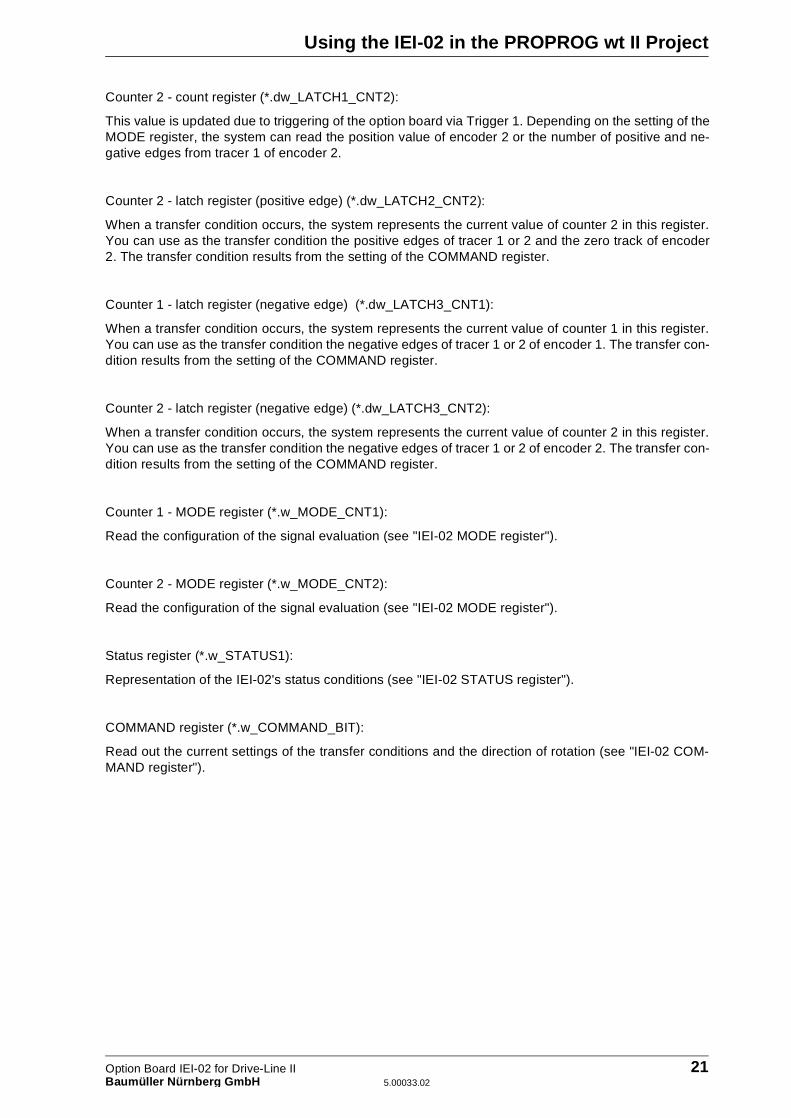
Counter 2 - count register (*.dw_LATCH1_CNT2):
This value is updated due to triggering of the option board via Trigger 1. Depending on the setting of theMODE register, the system can read the position value of encoder 2 or the number of positive and ne-gative edges from tracer 1 of encoder 2.
Counter 2 - latch register (positive edge) (*.dw_LATCH2_CNT2):
When a transfer condition occurs, the system represents the current value of counter 2 in this register.You can use as the transfer condition the positive edges of tracer 1 or 2 and the zero track of encoder2. The transfer condition results from the setting of the COMMAND register.
Counter 1 - latch register (negative edge) (*.dw_LATCH3_CNT1):
When a transfer condition occurs, the system represents the current value of counter 1 in this register.You can use as the transfer condition the negative edges of tracer 1 or 2 of encoder 1. The transfer con-dition results from the setting of the COMMAND register.
Counter 2 - latch register (negative edge) (*.dw_LATCH3_CNT2):
When a transfer condition occurs, the system represents the current value of counter 2 in this register.You can use as the transfer condition the negative edges of tracer 1 or 2 of encoder 2. The transfer con-dition results from the setting of the COMMAND register.
Counter 1 - MODE register (*.w_MODE_CNT1):
Read the configuration of the signal evaluation (see "IEI-02 MODE register").
Counter 2 - MODE register (*.w_MODE_CNT2):
Read the configuration of the signal evaluation (see "IEI-02 MODE register").
Status register (*.w_STATUS1):
Representation of the IEI-02's status conditions (see "IEI-02 STATUS register").
COMMAND register (*.w_COMMAND_BIT):
Read out the current settings of the transfer conditions and the direction of rotation (see "IEI-02 COM-MAND register").
Option Board IEI-02 for Drive-Line II 21Baumüller Nürnber g GmbH 5.00033.02
Using the IEI-02 in the PROPROG wt II Project
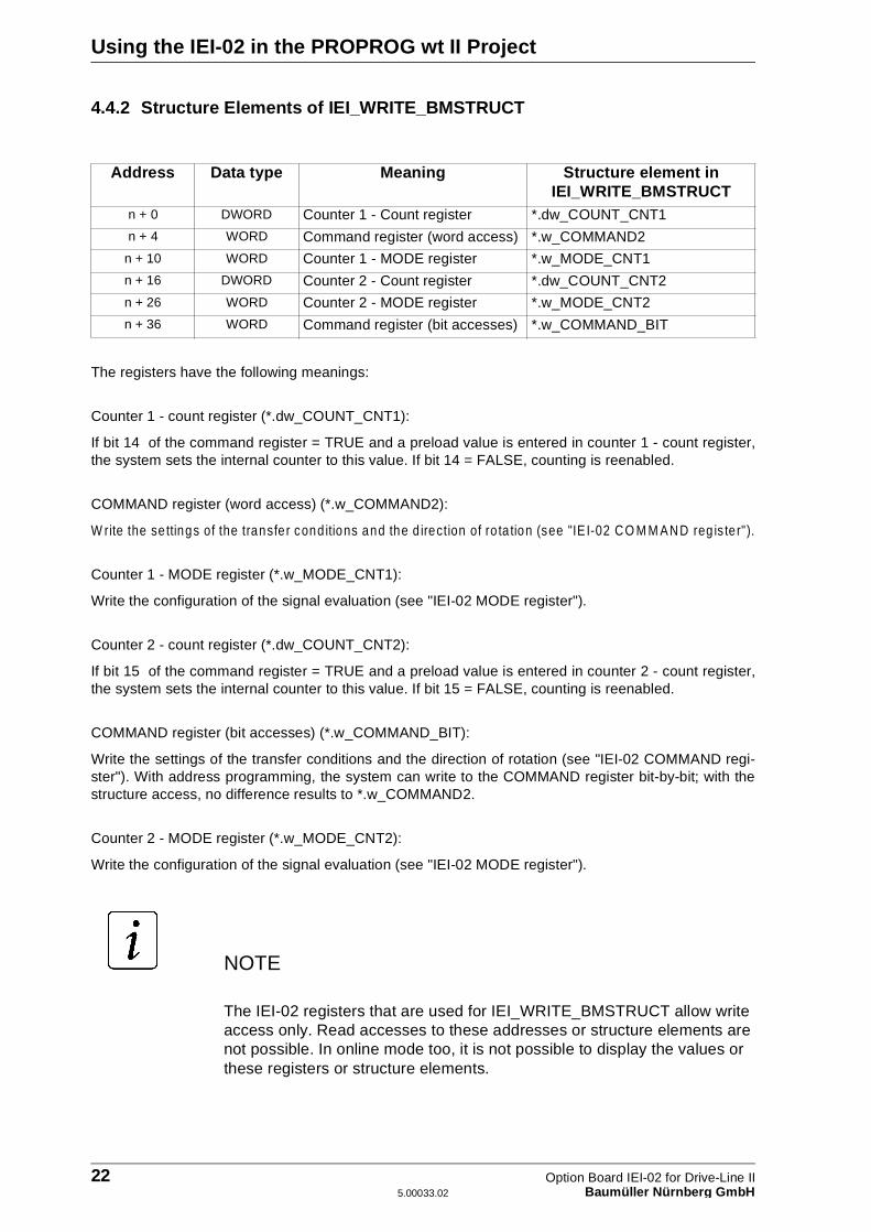
4.4.2 Structure Elements of IEI_WRITE_BMSTRUCT
The registers have the following meanings:
Counter 1 - count register (*.dw_COUNT_CNT1):
If bit 14 of the command register = TRUE and a preload value is entered in counter 1 - count register,the system sets the internal counter to this value. If bit 14 = FALSE, counting is reenabled.
COMMAND register (word access) (*.w_COMMAND2):
W rite the se ttings of the transfer cond itions and the d irection of ro ta tion (see "IE I-02 CO M M AND reg is te r").
Counter 1 - MODE register (*.w_MODE_CNT1):
Write the configuration of the signal evaluation (see "IEI-02 MODE register").
Counter 2 - count register (*.dw_COUNT_CNT2):
If bit 15 of the command register = TRUE and a preload value is entered in counter 2 - count register,the system sets the internal counter to this value. If bit 15 = FALSE, counting is reenabled.
COMMAND register (bit accesses) (*.w_COMMAND_BIT):
Write the settings of the transfer conditions and the direction of rotation (see "IEI-02 COMMAND regi-ster"). With address programming, the system can write to the COMMAND register bit-by-bit; with thestructure access, no difference results to *.w_COMMAND2.
Counter 2 - MODE register (*.w_MODE_CNT2):
Write the configuration of the signal evaluation (see "IEI-02 MODE register").
The IEI-02 registers that are used for IEI_WRITE_BMSTRUCT allow write access only. Read accesses to these addresses or structure elements are not possible. In online mode too, it is not possible to display the values or these registers or structure elements.
Address Data type Meaning Structure element in IEI_WRITE_BMSTRUCT
n + 0 DWORD Counter 1 - Count register *.dw_COUNT_CNT1
n + 4 WORD Command register (word access) *.w_COMMAND2
n + 10 WORD Counter 1 - MODE register *.w_MODE_CNT1
n + 16 DWORD Counter 2 - Count register *.dw_COUNT_CNT2
n + 26 WORD Counter 2 - MODE register *.w_MODE_CNT2
n + 36 WORD Command register (bit accesses) *.w_COMMAND_BIT
NOTE
22 Option Board IEI-02 for Drive-Line II5.00033.02 Baumüller Nürnber g GmbH
Using the IEI-02 in the PROPROG wt II Project
4.5 Configuring and Operating the IEI-02
4.5.1 The IEI-02 Trigger Signal
The IEI-02 needs a trigger signal, i.e. Trigger 1. You must interconnect Trigger signal Trigger 1 viafunction block (FB) OPT_INIT (see FB OPT_INIT in the �mega Drive-Line II technical description).
The IEI-02's count registers are updated via Trigger 1 of the option interface. If the counter readings aretriggered by a clock signal that triggers an event at the same time, it is possible to synchronize the ac-cesses to the registers to the event task. This procedure is absolutely necessary for many applicationsto guarantee real-time response, e.g. for encoder signals as a real leading axle.
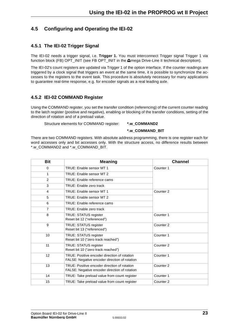
4.5.2 IEI-02 COMMAND Register
Using the COMMAND register, you set the transfer condition (referencing) of the current counter readingto the latch register (positive and negative), enabling or blocking of the transfer conditions, setting of thedirection of rotation and of a preload value.
Structure elements for COMMAND register: *.w_COMMAND2
*.w_COMMAND_BIT
There are two COMMAND registers. With absolute address programming, there is one register each forword accesses only and bit accesses only. With the structure access, no difference results between*.w_COMMAND2 and *.w_COMMAND_BIT.
Bit Meaning Channel0 TRUE: Enable sensor MT 1 Counter 1
1 TRUE: Enable sensor MT 2
2 TRUE: Enable reference cams
3 TRUE: Enable zero track
4 TRUE: Enable sensor MT 1 Counter 2
5 TRUE: Enable sensor MT 2
6 TRUE: Enable reference cams
7 TRUE: Enable zero track
8 TRUE: STATUS register Reset bit 12 (“referenced”)
Counter 1
9 TRUE: STATUS register Reset bit 13 (“referenced”)
Counter 2
10 TRUE: STATUS register Reset bit 10 (“zero track reached”)
Counter 1
11 TRUE: STATUS register Reset bit 10 (“zero track reached”)
Counter 2
12 TRUE: Positive encoder direction of rotation FALSE: Negative encoder direction of rotation
Counter 1
13 TRUE: Positive encoder direction of rotationFALSE: Negative encoder direction of rotation
Counter 2
14 TRUE: Take preload value from count register Counter 1
15 TRUE: Take preload value from count register Counter 2
Option Board IEI-02 for Drive-Line II 23Baumüller Nürnber g GmbH 5.00033.02
Using the IEI-02 in the PROPROG wt II Project
You must choose either
Tracer 1
or
Tracer 2
or
Zero track and tracer 1
or
Reference cam.
Reference cam: on a change from FALSE ⇒ TRUE, the system resets the hardware counter.
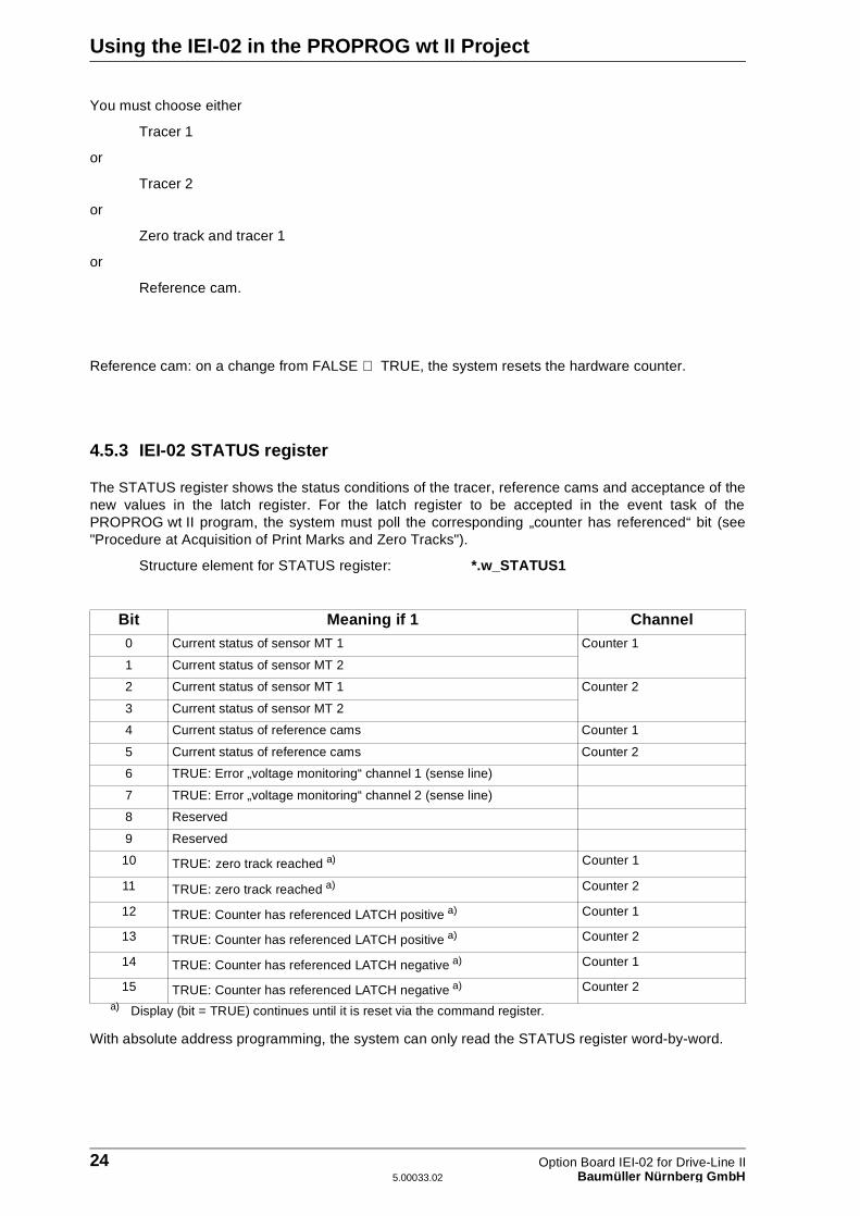
4.5.3 IEI-02 STATUS register
The STATUS register shows the status conditions of the tracer, reference cams and acceptance of thenew values in the latch register. For the latch register to be accepted in the event task of thePROPROG wt II program, the system must poll the corresponding „counter has referenced“ bit (see"Procedure at Acquisition of Print Marks and Zero Tracks").
Structure element for STATUS register: *.w_STATUS1
With absolute address programming, the system can only read the STATUS register word-by-word.
Bit Meaning if 1 Channel0 Current status of sensor MT 1 Counter 1
1 Current status of sensor MT 2
2 Current status of sensor MT 1 Counter 2
3 Current status of sensor MT 2
4 Current status of reference cams Counter 1
5 Current status of reference cams Counter 2
6 TRUE: Error „voltage monitoring“ channel 1 (sense line)
7 TRUE: Error „voltage monitoring“ channel 2 (sense line)
8 Reserved
9 Reserved
10 TRUE: zero track reached a)
a) Display (bit = TRUE) continues until it is reset via the command register.
Counter 1
11 TRUE: zero track reached a) Counter 2
12 TRUE: Counter has referenced LATCH positive a) Counter 1
13 TRUE: Counter has referenced LATCH positive a) Counter 2
14 TRUE: Counter has referenced LATCH negative a) Counter 1
15 TRUE: Counter has referenced LATCH negative a) Counter 2
24 Option Board IEI-02 for Drive-Line II5.00033.02 Baumüller Nürnber g GmbH

Using the IEI-02 in the PROPROG wt II Project
4.5.4 IEI-02 MODE Register
You must set the MODE register in accordance with the counter that is to be configured.
In rapid counter setting, the system counts on the count register both edges of the sensor connected totracer 1.
There are two MODE registers. One register each per counter channel.
Structure elements for the MODE register: *.w_MODE_CNT1: For counter channel 1
*.w_MODE_CNT2: For counter channel 2
Four-fold multiplexing of signal evaluation sets the maximum encoder resolution.
With absolute address programming, the system can only write to the MODE register word-by-word.
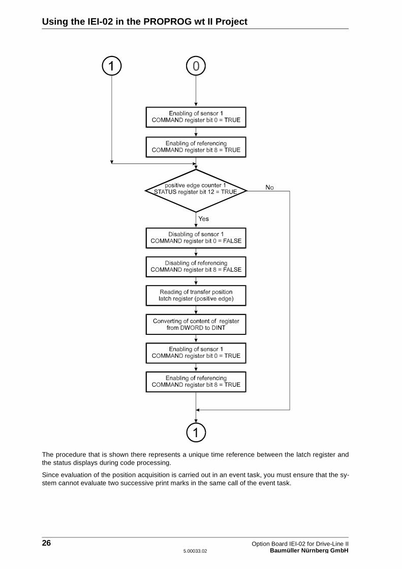
4.5.5 Procedure at Acquisition of Print Marks and Zero Tracks
Below, we will show you on the basis of an example the procedure for implementing print mark acquisi-tion on a positive edge of tracer 1 on encoder 1.
Set the MODE register to the appropriate multiplexing of the signal evaluation and direction of rotationfor encoder 1 (FB IEI02_INIT).
Follow the sequence of control and evaluation to print mark acquisition via the COMMAND and STATUSregisters that is shown in the following diagram:
Value Meaning16#0000 Four-fold multiplexing of encoder signal evaluation
16#0001 Two-fold multiplexing of encoder signal evaluation
16#0004 Single multiplexing of encoder signal evaluation
16#0085 Rapid counter for tracer 1, positive and negative edges
Option Board IEI-02 for Drive-Line II 25Baumüller Nürnber g GmbH 5.00033.02
Using the IEI-02 in the PROPROG wt II Project
The procedure that is shown there represents a unique time reference between the latch register andthe status displays during code processing.
Since evaluation of the position acquisition is carried out in an event task, you must ensure that the sy-stem cannot evaluate two successive print marks in the same call of the event task.
26 Option Board IEI-02 for Drive-Line II5.00033.02 Baumüller Nürnber g GmbH
Using the IEI-02 in the PROPROG wt II Project
For implementing: zero track acquisition, additionally note the following
� If tracer 1 is irrelevant to position acquisition, the signal must be permanently connected to 24 V.
� Enable the zero track in addition to tracer 1
� The transfer condition for the latch register is „enable zero track“ = TRUE and „enable tracer 1“ = TRUE
� Display of „zero track reached“ in the STATUS register is only an additional piece of information. Evaluation of the latch register (positive edge) must always be carried out with „Counter has refe-renced LATCH positive“. In any one direction of rotation, the distance of two „Counter has referenced LATCH positives“ is the zero track distance and, with this, the encoder resolution is one revolution.
Option Board IEI-02 for Drive-Line II 27Baumüller Nürnber g GmbH 5.00033.02

Using the IEI-02 in the PROPROG wt II Project
4.6 Function Initialization of the IEI-02 via FB IEI02_INIT
Function block IEI02_INIT initializes the IEI-02 option board. The system writes the IEI-02 registers ofthe specified option interface with the configuration that was created at the input.
FB IEI02_INIT needs BM_TYPES_20bd00 (or above).
Description
Input/output _BASE_WRITE:
At _BASE_WRITE, you must connect a global variable of data type IEI_WRITE_BMSTRUCT.
You m ust assign this variab le via dec lara tion o f global variables to the base address o f option board IE I-02 .
Example:
Option board IEI-02 for �mega Drive-Line II
_IeiBaseWrite AT %MB3.1000000 : IEI_WRITE_BMSTRUCT;
Where:
_IeiBaseWrite is the variable name with the data type short designati-on "_" for STRUCT
IEI_WRITE_BMSTRUCT is the data type%MB3.1000000 is the base address on the IEI-02 in option slot 1
Input u_CFG_CNT1_EVA:
For counter 1 encoder resolution with factor 1.For counter 1 encoder resolution with factor 2.For counter 1 encoder resolution with factor 4 (highest resolution).
Input u_CFG_CNT1_GRO:
For counter 1 direction of rotation 1 = clockwise, 0 = anti-clockwise.
Parameter input Data type Description_BASE_WRITE IEI_WRITE_BMSTRUCT Option interface with register structureu_CFG_CNT1_EVA UINT
(1, 2, 4)Multiplexing of evaluation counter 1
u_CFG_CNT1_GRO UINT(0, 1)
Direction of rotation of counter 1 clockwise or anti-clockwise
u_CFG_CNT2_EVA UINT(1, 2, 4)
Multiplexing of evaluation counter 2
u_CFG_CNT2_GRO UINT(0, 1)
Direction of rotation of counter 2 clockwise or anti-clockwise
x_CFG_MTMODE_CNT1 BOOL Rapid counter on sensor 1 counter 1x_CFG_MTMODE_CNT2 BOOL Rapid counter on sensor 1 counter 2 x_EN BOOL Enable
Parameter output Data type Description_BASE_WRITE IEI_WRITE_BMSTRUCT Option interface with register structure
28 Option Board IEI-02 for Drive-Line II5.00033.02 Baumüller Nürnber g GmbH
Using the IEI-02 in the PROPROG wt II Project
Input u_CFG_CNT2_EVA:
For counter 2 encoder resolution with factor 1.For counter 2 encoder resolution with factor 2.For counter 2 encoder resolution with factor 4 (highest resolution).
Input u_CFG_CNT2_GRO:
For counter 2 direction of rotation 1 = clockwise, 0 = anti-clockwise.
Input x_CFG_MTMODE_CNT1:
For counter 1 operating mode rapid counter on tracer 1.TRUE = activated (both edges are counted).FALSE = deactivated (tracer 1 or 2 takes the position).
Input x_CFG_MTMODE_CNT2:
For counter 2 operating mode rapid counter on tracer 1.TRUE = activated (both edges are counted).FALSE = deactivated (tracer 1 or 2 takes the position).
Input x_EN:
TRUE = The IEI-02 is initialized.FALSE = No initialization enable.
The FB IEI02_INIT initializes the specified IEI-02 counter module with regard to multiplexing of evalua-tion, the direction of rotation and operating mode (position acquisition or counting the latches of tracer1, rapid counter).
Instead of counting a position via a square-wave incremental encoder signal, the system can count atracer detection (operating mode rapid counter to both edges of tracer 1).
The counter group is not initialized until after a general enable x_EN=TRUE.
To configure functions of the IEI-02 for a register controller, you must use function block REG_CONTROL_INIT from library REGISTER_DLII_20bd00 (or above). FB IEI02_INIT is a component of FB REG_CONTROL_INIT.
Error evaluation: None.
NOTE
Option Board IEI-02 for Drive-Line II 29Baumüller Nürnber g GmbH 5.00033.02
Using the IEI-02 in the PROPROG wt II Project
30 Option Board IEI-02 for Drive-Line II5.00033.02 Baumüller Nürnber g GmbH
Index
3
0
8
5
43
5 INDEX
A
Appropriate Use .......................................... 6Areas of application ..................................... 7
B
BM_TYPES_20bd00 ................................. 15
C
COMMAND register .................... 21, 22, 23Count register ............................. 20, 21, 22
D
Danger Information ..................................... 5Data type
IEI_READ_BMSTRUCT ...................... 16IEI_WRITE_BMSTRUCT .............. 16, 17
Data types ................................................ 16Declaring variables .................................... 18
E
Encoder connection ................................... 11
F
FB IEI02_INIT ........................................... 28
G
Global variable .......................................... 18
I
IEI_DLII_20bd00 ....................................... 15IEI_READ_BMSTRUCT ............................ 20IEI_WRITE_BMSTRUCT ........................... 22IEI02_INIT ................................................ 28Initialization ............................................... 28
L
Latch register .............................. 20, 21, 24
LED ......................................................... 1
M
MODE register ............................ 21, 22, 25
O
Option slot ........................................... 9, 1
P
Pin assignmentEncoder connection ............................ 11Supply voltage .................................... 12
Position acquisition ..................................... 7print mark acquisition ................................ 25Properties ..................................................
Q
Qualified Personnel ..................................... 6
R
Rapid counter ...................................... 7, 2Reference cams ....................................... 24Register access ........................................ 15Register address ...................................... 20REGISTER_DLII_20bd00 .......................... 15
S
Safety Information ....................................... 5Sample configuration ........................... 9, 10STATUS register ............................... 21, 24Structure elements ............................. 15, 20SYSTEM_DLII_20bd00 ............................. 15
T
Tracer ...................................................... 2Trigger signal ........................................... 2
Option Board IEI-02 for Drive-Line II 31Baumüller Nürnber g GmbH 5.00033.02
Index
Z
Zero track acquisition ................................ 27
32 Option Board IEI-02 for Drive-Line II5.00033.02 Baumüller Nürnber g GmbH