Embed Size (px)
Citation preview
December 2015 CG-PRC037A-GB
Option Guide
Conquest Air-cooled Liquid Chillers with
Scroll compressors
Models CGAX & CXAX 015 to 060

Table of contents . 1 CONQUEST™ Range Overview ........................................................................... 1
1.1 CGAX Range ............................................................................................................... 1 1.2 CXAX Range ................................................................................................................ 2 1.3 Coil’s distribution .......................................................................................................... 3 1.4 Unit Appearance .......................................................................................................... 4
2 Efficiency level, Digit 12 ....................................................................................... 6 2.1 Standard efficiency, Digit 12 = 1 .................................................................................. 6 2.2 High efficiency, Digit 12 = 2 ......................................................................................... 6 2.3 AC & EC fans Characteristics. ..................................................................................... 6
3 Operating map – airside, Digit 15 ...................................................................... 10 3.1 Standard Ambient temperature, Digit 15 = A ............................................................. 10 3.2 Low ambient temperature, Digit 15 = C ..................................................................... 11
4 Freeze protection, Digit 18 ................................................................................. 12 4.1 None, Digit 18 = X ...................................................................................................... 12 4.2 With electric heaters, Digit 18 = 2 .............................................................................. 12 4.3 With pump activation, Digit 18 = 3 ............................................................................. 13
5 Operating map water side, Digit 21 ................................................................... 15 5.1 Comfort cooling, Digit 21 = A ..................................................................................... 15 5.2 Process cooling, Digit 21 = B ..................................................................................... 15
6 Water connection, Digit 22 ................................................................................. 16 6.1 Grooved pipe connection (standard) digit 22 = 1 ....................................................... 16 6.2 Grooved pipe connection with coupling and pipe stub digit 22 = 3 ............................ 16
7 Condenser coating, Digit 23 ............................................................................... 18 7.1 Standard aluminum fins, Digit 23 = B ......................................................................... 18 7.2 Epoxy aluminum fins Digit 23 = E. ............................................................................. 19 7.3 Aluminum Micro Channel, Digit 23 = H. ..................................................................... 19 7.4 E-coated Micro Channel, Digit 23 = J ........................................................................ 22
8 Heat Recovery, Digit 24 ...................................................................................... 23 8.1 None Heat Recovery, Digit 24 = X ............................................................................. 23 8.2 Partial Heat Recovery (PHR), Digit 24 = 2 ................................................................. 23
9 Starter type, Digit 26 ........................................................................................... 25 9.1 Across the Line Starter/Direct on Line Digit 26= A ..................................................... 25 9.2 Solid-state Soft Starter Digit 26 = B ........................................................................... 25
10 Human interface, Digit 30 ................................................................................... 26 10.1 Without interface, Digit 30= X .................................................................................... 26 10.2 Interface PGD1, Digit 30= A ....................................................................................... 26 10.3 Interface PGDTouch , Digit 30 = B ............................................................................. 26
11 Smart Com protocol, Digit 31 ............................................................................. 28 11.1 No remote digital communication, Digit 31 = X .......................................................... 28 11.2 Modbus interface, Digit 31 = 1 ................................................................................... 28 11.3 LonTalk® interface, Digit 31 = 2 ................................................................................ 28 11.4 BACNet™ Interface; Digit 31= 4 ................................................................................ 29
12 External customer input/output option, Digit 32 .............................................. 30 12.1 Without, Digit 32 = X .................................................................................................. 30 12.2 With, Digit 32 = A ....................................................................................................... 30
13 Smart Sequencer, Digit 33 .................................................................................. 32 13.1 Without, Digit 33 = X .................................................................................................. 32 13.2 With Smart Sequencer, Digit 33 = 1 ........................................................................... 32
14 Hydraulic module, Digit 35 ................................................................................. 34 14.1 No pumps and no contactors, Digit 35 = X ................................................................ 35 14.2 Contactors single pump, Digit 35 = 2 ......................................................................... 35 14.3 Contactors dual pump, Digit 35 = 4 ............................................................................ 35 14.4 Single pump standard pressure, Digit 35 = 5 ............................................................. 36

Table of contents .
14.5 Single pump high pressure, Digit 35 = 6 .................................................................... 38 14.6 Dual pump standard pressure, Digit 35 = 7 ............................................................... 39
15 Smart Flow Control, Digit 36 .............................................................................. 40 15.1 No pump flow control; Digit 36 = X ............................................................................. 40 15.2 Manual flow control, Digit 36 = B ............................................................................... 40 15.3 Variable primary flow (Constant ΔT), Digit 36 = C ..................................................... 41 15.4 Variable primary flow (Constant ΔP), Digit 36 = D ..................................................... 41
16 Buffer tank, Digit 37 ............................................................................................ 43 16.1 Without Buffer tank; Digit 37 = X ................................................................................ 43 16.2 Buffer Tank, Digit 37 = 1 ............................................................................................ 43
17 Installation accessory, Digit 39 .......................................................................... 45 17.1 None, Digit 39 = 1 ...................................................................................................... 45 17.2 Neoprene Pads, Digit 39 = 4 ...................................................................................... 45
18 Acoustic level, Digit 41 ....................................................................................... 47 18.1 Standard Noise (SN), digit 15 = X .............................................................................. 47 18.2 Low Noise (LN), digit 15 = L ....................................................................................... 47 18.3 HESP, Digit 41 = 2 ..................................................................................................... 49
19 Condenser protection, Digit 42 .......................................................................... 50 19.1 No option, Digit 42 = X ............................................................................................... 50 19.2 Condenser guard grill, Digit 42 = A ............................................................................ 50
20 Literature Language, Digit 44 ............................................................................. 51
21 Under/over voltage protection, Digit 45 ............................................................ 52 21.1 None, Digit 45 = X ...................................................................................................... 52 21.2 Included, Digit 45 = 1 ................................................................................................. 52
22 Suplemental Heat Control, Digit 49 ................................................................... 53 22.1 Without, Digit 49 = X .................................................................................................. 53 22.2 With, Digit 49 = 1........................................................................................................ 53
23 Design Special, Digit 50 ...................................................................................... 54
1 | P a g e
1 CONQUEST™ Range Overview
Before explaining the different options and accessories available, let’s first take a look at the
current range and review the definition of CONQUEST™ Air-cooled heat pumps and chillers.
The CONQUEST Air-cooled heat pumps and chillers family covers a capacity range between
40 kW and 165 kW, which includes Cooling only and Heat pump units. For the “Cooling only”
unit, it is called CGAX and the Heat pump is named CXAX. The units come divided by its
efficiency and their acoustic level which won’t comprise the efficiencies.
The best value chiller of the market
Optimized efficiencies
Lowest sound levels
High quality finish
Smart and versatile
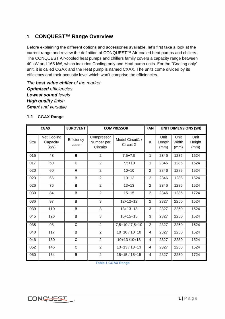
1.1 CGAX Range
CGAX EUROVENT COMPRESSOR FAN UNIT DIMENSIONS (SN)
Size Net Cooling
Capacity
(kW)
Efficiency
class
Compressor
Number per
Circuits
Model Circuit1 /
Circuit 2 #
Unit
Length
(mm)
Unit
Width
(mm)
Unit
Height
(mm)
015 43 B 2 7,5+7,5 1 2346 1285 1524
017 50 C 2 7,5+10 1 2346 1285 1524
020 60 A 2 10+10 2 2346 1285 1524
023 66 B 2 10+13 2 2346 1285 1524
026 76 B 2 13+13 2 2346 1285 1524
030 84 B 2 15+15 2 2346 1285 1724
036 97 B 3 12+12+12 2 2327 2250 1524
039 110 B 3 13+13+13 3 2327 2250 1524
045 126 B 3 15+15+15 3 2327 2250 1524
035 98 C 2 7,5+10 / 7,5+10 2 2327 2250 1524
040 117 B 2 10+10 / 10+10 4 2327 2250 1524
046 130 C 2 10+13 /10+13 4 2327 2250 1524
052 146 C 2 13+13 / 13+13 4 2327 2250 1524
060 164 B 2 15+15 / 15+15 4 2327 2250 1724
Table 1 CGAX Range
2 | P a g e
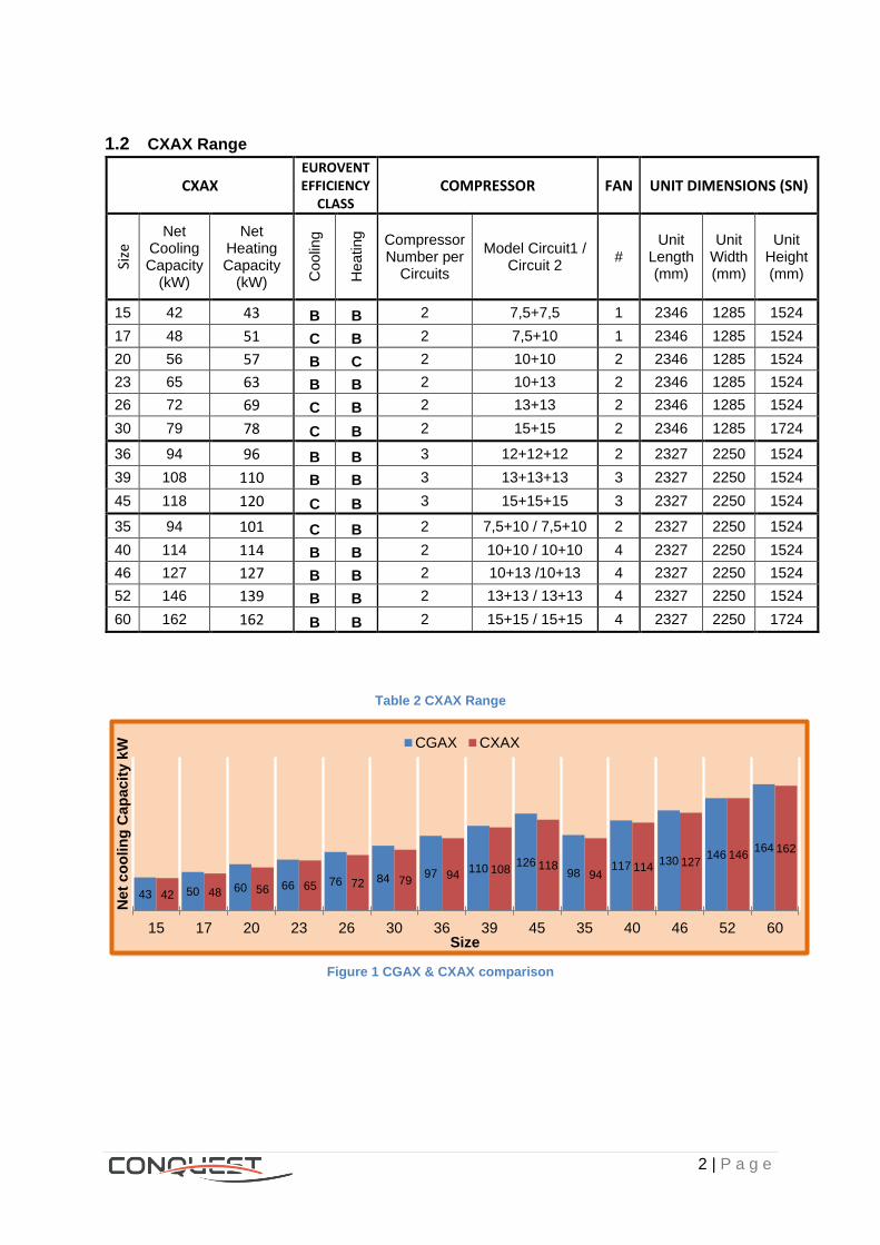
1.2 CXAX Range
CXAX EUROVENT EFFICIENCY
CLASS COMPRESSOR FAN UNIT DIMENSIONS (SN)
Size
Net Cooling Capacity
(kW)
Net Heating Capacity
(kW) Co
olin
g
He
ating
Compressor Number per
Circuits
Model Circuit1 / Circuit 2
# Unit
Length (mm)
Unit Width (mm)
Unit Height (mm)
15 42 43 B B 2 7,5+7,5 1 2346 1285 1524
17 48 51 C B 2 7,5+10 1 2346 1285 1524
20 56 57 B C 2 10+10 2 2346 1285 1524
23 65 63 B B 2 10+13 2 2346 1285 1524
26 72 69 C B 2 13+13 2 2346 1285 1524
30 79 78 C B 2 15+15 2 2346 1285 1724
36 94 96 B B 3 12+12+12 2 2327 2250 1524
39 108 110 B B 3 13+13+13 3 2327 2250 1524
45 118 120 C B 3 15+15+15 3 2327 2250 1524
35 94 101 C B 2 7,5+10 / 7,5+10 2 2327 2250 1524
40 114 114 B B 2 10+10 / 10+10 4 2327 2250 1524
46 127 127 B B 2 10+13 /10+13 4 2327 2250 1524
52 146 139 B B 2 13+13 / 13+13 4 2327 2250 1524
60 162 162 B B 2 15+15 / 15+15 4 2327 2250 1724
Table 2 CXAX Range
Figure 1 CGAX & CXAX comparison
43 50 60 66 76 84 97 110 126
98 117 130
146 164
42 48 56 65 72 79 94 108 118
94 114 127
146 162
15 17 20 23 26 30 36 39 45 35 40 46 52 60
Ne
t c
oo
lin
g C
ap
ac
ity k
W
Size
CGAX CXAX
3 | P a g e
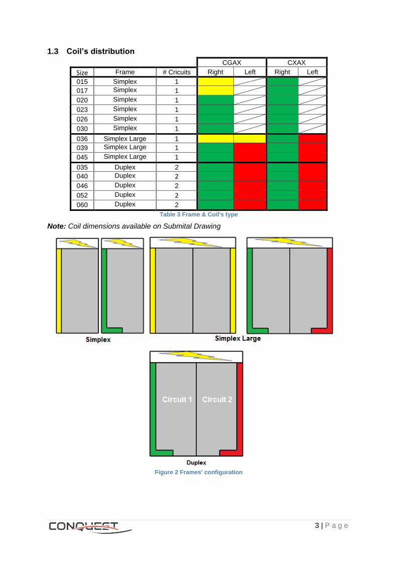
1.3 Coil’s distribution
CGAX CXAX
Size Frame # Cricuits Right Side
Left Side
Right Side
Left Side 015 Simplex 1
017 Simplex 1
020 Simplex 1
023 Simplex 1
026 Simplex 1
030 Simplex 1
036 Simplex Large 1 039 Simplex Large 1
045 Simplex Large 1
035 Duplex 2 040 Duplex 2
046 Duplex 2
052 Duplex 2
060 Duplex 2 Table 3 Frame & Coil's type
Note: Coil dimensions available on Submital Drawing
Figure 2 Frames' configuration
4 | P a g e
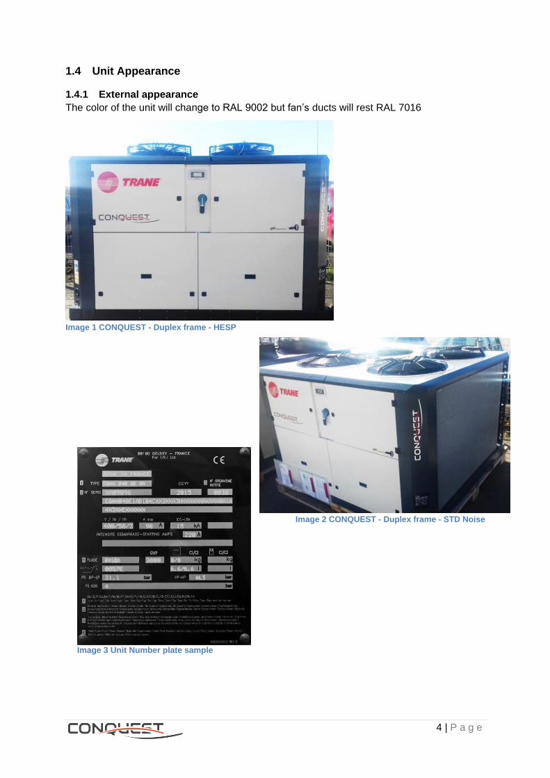
1.4 Unit Appearance
1.4.1 External appearance
The color of the unit will change to RAL 9002 but fan’s ducts will rest RAL 7016
Image 1 CONQUEST - Duplex frame - HESP
Image 2 CONQUEST - Duplex frame - STD Noise
Image 3 Unit Number plate sample

5 | P a g e
1.4.2 Inside apparence
Image 4 Unit w/o hydraulic module
Image 5 Unit with hydraulic module
Image 6 Electrical panel

6 | P a g e
2 Efficiency level, Digit 12
2.1 Standard efficiency, Digit 12 = 1
2.1.1 Description
EER at 12/7 OAT=35°C: SE is class B or C (Eurovent efficiency) when operating at full load.
Standard efficiency, units use AC fan motors with three-phase on the condenser. The motor
and the ball bearings are permanently lubricated and overload protection is provided.
However, if the unit has Low Ambient (Digit 15= C) then it will have one EC fan per circuit.
2.2 High efficiency, Digit 12 = 2
2.2.1 Description
HE version remains with the same compressors, exchangers and airflow of SE version.
The EER in High efficiency unit is the same value of a standard unit, but the ESEER is much
higher because it counts with an adaptive control that improves the efficiency in partial load
operation. Best compromise between number of compressors in operation and airflow (fans’
rotation)
High efficiency units are always equipped EC fan brushless motor, operating with direct
current. EC Fan: the basis is similar to the principle of a frequency inverter; the motor speed
depends on the voltage provided by the integrated module. All fans will be driven at the same
speed.
2.2.2 Benefits
High efficiency and a significant reduction of energy consumption at partial load.
2.3 AC & EC fans Characteristics.
The motors of both fans are Insulation class F and Ingress protection marking IP54.
Image 7 AC fans model
Image 8 EC fans model
AC Motor Number of poles: 8
Nominal Speed: 680 RPM
Same grid design as AC fan With EC motor

7 | P a g e
2.3.1 Fan’s type
Figure 3 Fans' distribution
FAN CKT 1 FAN CKT 2
1A 1B 1C 2A 2B
Simplex
SE - Std Ambient
High/Low Speed (AC fan)
High Speed (AC fan) if any
SE - Low Ambient
Variable Speed (EC fan)
High Speed (AC fan) if any
HE/HESP Variable Speed
(EC fan) Variable Speed (EC fan) if any
Simplex Large
SE - Std Ambient
High/Low Speed (AC fan)
High Speed (AC fan)
High Speed (AC fan)
SE - Low Ambient
Variable Speed (EC fan)
High Speed (AC fan)
High Speed (AC fan)
HE/HESP Variable Speed
(EC fan) Variable Speed
(EC fan)
Variable Speed
(EC fan)
Duplex
SE - Std Ambient
High/Low Speed (AC fan)
High Speed (AC fan) if any
High/Low Speed (AC fan)
High Speed (AC fan) if any
SE - Low Ambient
Variable Speed (EC fan)
High Speed (AC fan) if any
Variable Speed (EC fan)
High Speed (AC fan) if any
HE/HESP Variable Speed
(EC fan) Variable Speed (EC fan) if any
Variable Speed (EC fan)
Variable Speed (EC fan) if any
Table 4 Fans operation
8 | P a g e
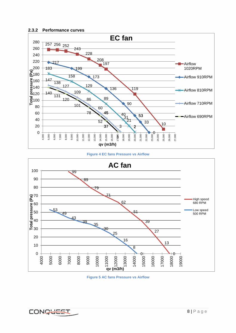
2.3.2 Performance curves
Figure 4 EC fans Pressure vs Airflow
Figure 5 AC fans Pressure vs Airflow
10
119
197 208
228
243 252 256 257
53
0
33
53
90
136
173
199
217
2 2
21 31
40
89
129
158
183
45
3
45
60
86
109
127 138
147
37
3
37
52
78
101
120 131
140
0
20
40
60
80
100
120
140
160
180
200
220
240
260
2804
,00
0
5,0
00
6,0
00
7,0
00
8,0
00
9,0
00
10,0
00
11,0
00
12,0
00
13,0
00
14,0
00
15,0
00
16,0
00
17,0
00
18,0
00
19,0
00
20,0
00
21,0
00
22,0
00
23,0
00
24,0
00
25,0
00
26,0
00
27,0
00
To
tal
pre
ss
ure
(P
a)
qv (m3/h)
EC fan
Airflow1020RPM
Airflow 910RPM
Airflow 810RPM
Airflow 710RPM
Airflow 690RPM
0
13
27
39
51
62
71
79
89
99
0
8
16
25
30 35
39 43
49 53
0
10
20
30
40
50
60
70
80
90
100
400
0
500
0
600
0
700
0
800
0
900
0
100
00
110
00
120
00
130
00
140
00
150
00
160
00
170
00
180
00
190
00
To
tal
pre
ss
ure
(P
a)
qv (m3/h)
AC fan
High speed680 RPM
Low speed500 RPM
9 | P a g e
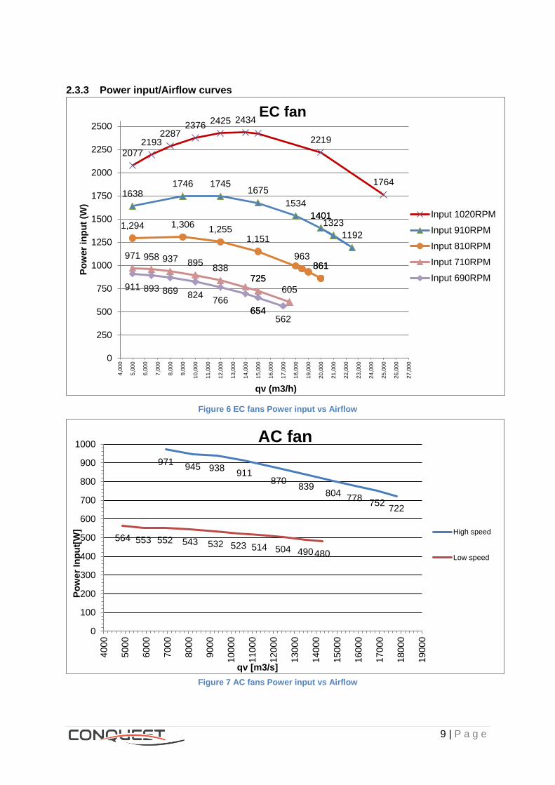
2.3.3 Power input/Airflow curves
Figure 6 EC fans Power input vs Airflow
Figure 7 AC fans Power input vs Airflow
1764
2219
2434 2425 2376
2287 2193
2077
1401
1192
1323 1401
1534
1675 1745 1746
1638
861 861 963
1,151 1,255
1,306 1,294
725
605
725 838
895 937 958 971
654 562
654 766
824 869 893 911
0
250
500
750
1000
1250
1500
1750
2000
2250
25004
,00
0
5,0
00
6,0
00
7,0
00
8,0
00
9,0
00
10,0
00
11,0
00
12,0
00
13,0
00
14,0
00
15,0
00
16,0
00
17,0
00
18,0
00
19,0
00
20,0
00
21,0
00
22,0
00
23,0
00
24,0
00
25,0
00
26,0
00
27,0
00
Po
wer
inp
ut
(W)
qv (m3/h)
EC fan
Input 1020RPM
Input 910RPM
Input 810RPM
Input 710RPM
Input 690RPM
722 752
778 804
839 870
911 938 945
971
480 490 504 514 523 532 543 552 553 564
0
100
200
300
400
500
600
700
800
900
1000
400
0
500
0
600
0
700
0
800
0
900
0
100
00
110
00
120
00
130
00
140
00
150
00
160
00
170
00
180
00
190
00
Po
wer
Inp
ut[
W]
qv [m3/s]
AC fan
High speed
Low speed
10 | P a g e
3 Operating map – airside, Digit 15
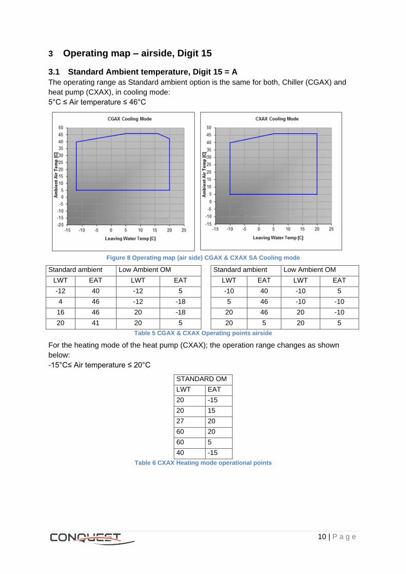
3.1 Standard Ambient temperature, Digit 15 = A
The operating range as Standard ambient option is the same for both, Chiller (CGAX) and
heat pump (CXAX), in cooling mode:
5°C ≤ Air temperature ≤ 46°C
Figure 8 Operating map (air side) CGAX & CXAX SA Cooling mode
Standard ambient
OM
Low Ambient OM
(Requires 1 EC fan/circuit
minimum)
Standard ambient
OM
Low Ambient OM
(Requires 1 EC
fan/circuit minimum) LWT EAT LWT EAT LWT EAT LWT EAT
-12 40 -12 5 -10 40 -10 5
4 46 -12 -18 5 46 -10 -10
16 46 20 -18 20 46 20 -10
20 41 20 5 20 5 20 5
Table 5 CGAX & CXAX Operating points airside
For the heating mode of the heat pump (CXAX); the operation range changes as shown
below:
-15°C≤ Air temperature ≤ 20°C
STANDARD OM
LWT EAT
20 -15
20 15
27 20
60 20
60 5
40 -15
Table 6 CXAX Heating mode operational points

11 | P a g e
Figure 9 Operating map CXAX SA Heating mode
3.2 Low ambient temperature, Digit 15 = C
- Low ambient Chiller (CGAX): -18°C ≤ Air temperature ≤ 46°C
- Low ambient Heat pump (CXAX): -10°C ≤ Air temperature ≤ 46°C
- With Low ambient option, EC fans are mounted on the unit. EC fans allow operation
with air temperature down to -18/-10 ° C by reducing the air flow when necessary.
Figure 10 Operating map CGAX & CXAX LA cooling mode
12 | P a g e
4 Freeze protection, Digit 18
4.1 None, Digit 18 = X
Glycol in the water loop in charge of the freeze protection.
4.2 With electric heaters, Digit 18 = 2
4.2.1 Application
- When the unit is exposed to ambient temperature between 0°C and -18°C.
- When the unit needs to be protected from freezing (no glycol in the water loop).
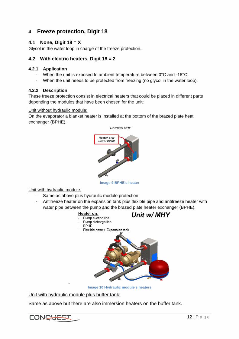
4.2.2 Description
These freeze protection consist in electrical heaters that could be placed in different parts
depending the modules that have been chosen for the unit:
Unit without hydraulic module:
On the evaporator a blanket heater is installed at the bottom of the brazed plate heat
exchanger (BPHE).
Image 9 BPHE's heater
Unit with hydraulic module:
- Same as above plus hydraulic module protection
- Antifreeze heater on the expansion tank plus flexible pipe and antifreeze heater with
water pipe between the pump and the brazed plate heater exchanger (BPHE).
- Image 10 Hydraulic module's heaters
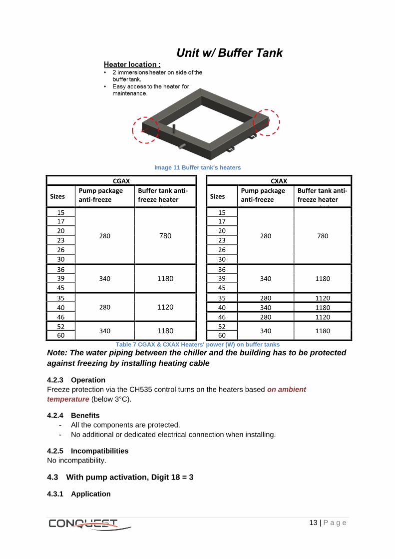
Unit with hydraulic module plus buffer tank:
Same as above but there are also immersion heaters on the buffer tank.
13 | P a g e
Image 11 Buffer tank's heaters
CGAX CXAX
Sizes Pump package anti-freeze heater power (W)
Buffer tank anti-freeze heater power (W)
Sizes Pump package anti-freeze heater power (W)
Buffer tank anti-freeze heater power (W)
15
280 780
15
280 780
17 17
20 20
23 23
26 26
30 30
36 340 1180
36 340 1180 39 39
45 45
35 280 1120
35 280 1120
40 40 340 1180
46 46 280 1120
52 340 1180
52 340 1180
60 60 Table 7 CGAX & CXAX Heaters' power (W) on buffer tanks
Note: The water piping between the chiller and the building has to be protected
against freezing by installing heating cable
4.2.3 Operation
Freeze protection via the CH535 control turns on the heaters based on ambient
temperature (below 3°C).
4.2.4 Benefits
- All the components are protected.
- No additional or dedicated electrical connection when installing.
4.2.5 Incompatibilities
No incompatibility.
4.3 With pump activation, Digit 18 = 3
4.3.1 Application
14 | P a g e
No heaters are provided but the anti-freeze protection is possible with the pump activation
using external temperature sensor. This system allows reducing the price and consumption
of the unit.
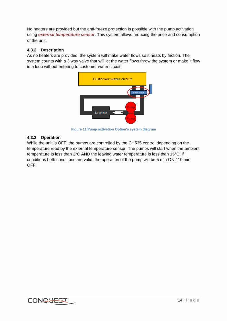
4.3.2 Description
As no heaters are provided, the system will make water flows so it heats by friction. The
system counts with a 3 way valve that will let the water flows throw the system or make it flow
in a loop without entering to customer water circuit.
Figure 11 Pump activation Option’s system diagram
4.3.3 Operation
While the unit is OFF, the pumps are controlled by the CH535 control depending on the
temperature read by the external temperature sensor. The pumps will start when the ambient
temperature is less than 2°C AND the leaving water temperature is less than 15°C; if
conditions both conditions are valid, the operation of the pump will be 5 min ON / 10 min
OFF.
15 | P a g e
Leaving water temperature
5 Operating map water side, Digit 21
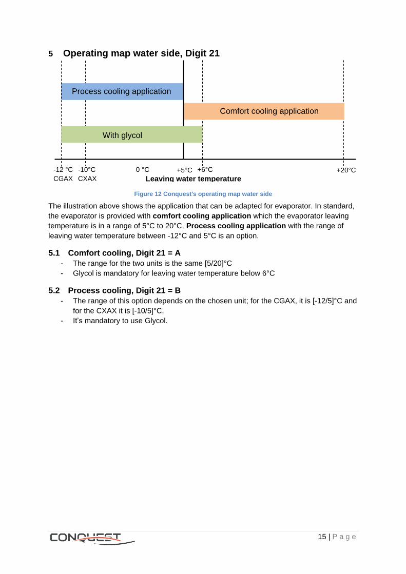
Figure 12 Conquest's operating map water side
The illustration above shows the application that can be adapted for evaporator. In standard,
the evaporator is provided with comfort cooling application which the evaporator leaving
temperature is in a range of 5°C to 20°C. Process cooling application with the range of
leaving water temperature between -12°C and 5°C is an option.
5.1 Comfort cooling, Digit 21 = A
- The range for the two units is the same [5/20]°C
- Glycol is mandatory for leaving water temperature below 6°C
5.2 Process cooling, Digit 21 = B
- The range of this option depends on the chosen unit; for the CGAX, it is [-12/5]°C and
for the CXAX it is [-10/5]°C.
- It’s mandatory to use Glycol.
Process cooling application
-12 °C -10°C
CGAX CXAX
0 °C +6°C +5°C +20°C
With glycol
Comfort cooling application
16 | P a g e
6 Water connection, Digit 22 There are 2 ways which are suggested by Trane for water pipe connections (cold water and
HR hot water (if any) connections).
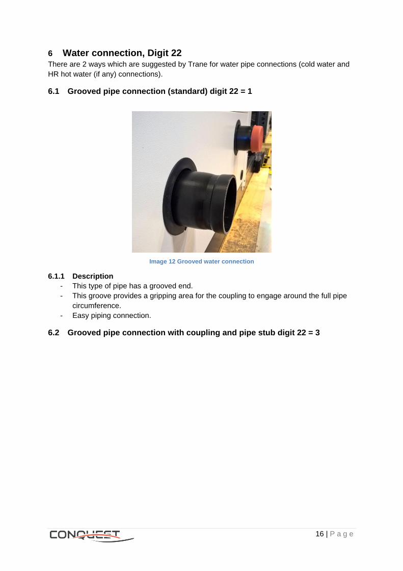
6.1 Grooved pipe connection (standard) digit 22 = 1
Image 12 Grooved water connection
6.1.1 Description
- This type of pipe has a grooved end.
- This groove provides a gripping area for the coupling to engage around the full pipe
circumference.
- Easy piping connection.
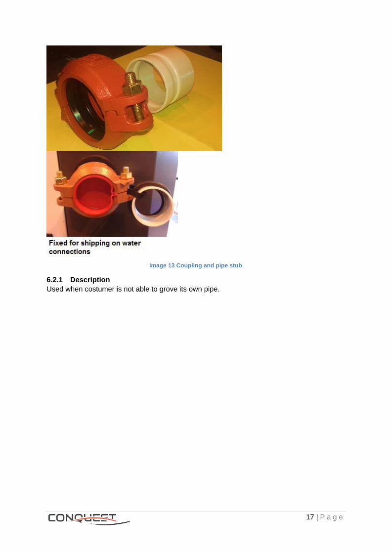
6.2 Grooved pipe connection with coupling and pipe stub digit 22 = 3
17 | P a g e
Image 13 Coupling and pipe stub
6.2.1 Description
Used when costumer is not able to grove its own pipe.

18 | P a g e
7 Condenser coating, Digit 23
7.1 Standard aluminum fins, Digit 23 = B
Image 14 Aluminum fins
7.1.1 Application
- When the chiller is installed in standard condition
- Non polluted ambiance
- Non corrosive ambiance
7.1.2 Description
Aluminum fin is a standard fin used on all CXAX heat pumps.
7.1.3 Incompatibilities
CGAX.

19 | P a g e
7.2 Epoxy aluminum fins Digit 23 = E.
Image 15 Gold epoxy aluminum fins
7.2.1 Application
- When the heat pump is requested for coastal or salt mist environments.
- When the aluminum fin is exposed to hard weather conditions (acid rain, moisture,
pollution, salt …).
7.2.2 Description
- The fins are made out of aluminum coated sheets.
- Condenser epoxy coated; epoxy slows down the corrosion process on the aluminum
fins when the unit is installed on sea side or in a polluted area.
- Epoxy layer is between 2 to 3 µm thick per surface
7.2.3 Benefits
This option allows installation near the sea and avoids aluminum corrosion. The epoxy also
provides a barrier protection at the fin collar to stop galvanic corrosion action between the
aluminum fins and the copper tubes.
7.2.4 Incompatibilities
CGAX
7.2.5 More detail
For information, there are 192 fins per foot installed in the condenser.
See engineering bulletin PROD_PRB004_E4 on Litweb.
7.3 Aluminum Micro Channel, Digit 23 = H.

20 | P a g e
Image 16 Micro Channel Heat Exchanger
7.3.1 Application
Aluminum Micro Channel Heat Exchanger is standard for all CGAX chillers.
7.3.2 Description
- The fully-brazed construction micro channel coil increases the coil rigidity making
them more rugged to resist the rigors of job site handling and damage due to
shipping. The micro channel coil's headers, tubes and fins are assembled and then
sprayed with a powder flux bonding agent. The coil is then sent through a large
controlled air automated brazing furnace that completely joins these separate pieces
as one solid micro channel coil.
- The bottom and top tubes of each coil section are always inactive refrigerant paths,
this is done to prevent refrigerant leaks due to corrosion that may be present from
moisture resting between the top or bottom tube and the gasket material and also
serve as a buffer during the installation and removal of the coil section.
21 | P a g e
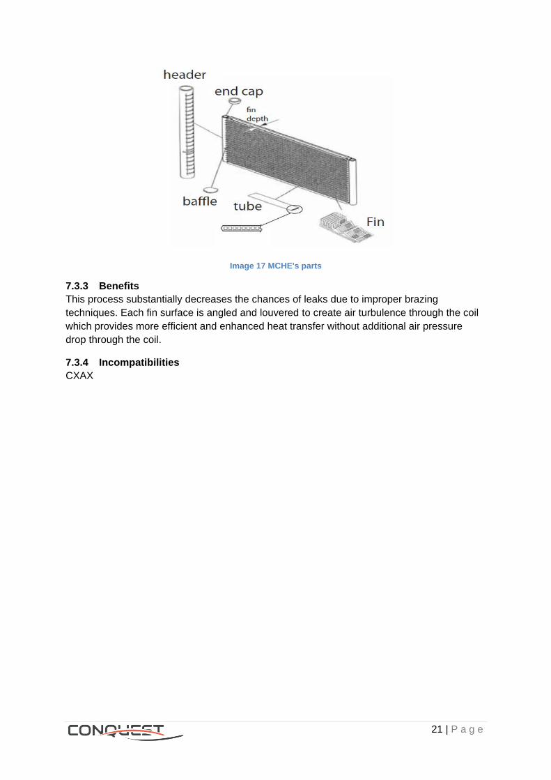
Image 17 MCHE's parts
7.3.3 Benefits
This process substantially decreases the chances of leaks due to improper brazing
techniques. Each fin surface is angled and louvered to create air turbulence through the coil
which provides more efficient and enhanced heat transfer without additional air pressure
drop through the coil.
7.3.4 Incompatibilities
CXAX

22 | P a g e
7.4 E-coated Micro Channel, Digit 23 = J
Image 18 E-Coated MCHE
7.4.1 Application
Refer to the following document to know when is necessary to apply the coating PROD_PRB
005 A, on LitWeb.
7.4.2 Description
The condenser is provided already coated before unit assembly.
7.4.3 Benefits
This option allows installation in high chemical concentrated or coastal environment and
avoids aluminum corrosion.
7.4.4 Incompatibilities
CXAX
23 | P a g e
8 Heat Recovery, Digit 24
8.1 None Heat Recovery, Digit 24 = X
All refrigerant’s heat is rejected to the atmosphere.
8.2 Partial Heat Recovery (PHR), Digit 24 = 2
8.2.1 Application
When part of the rejected heat needs to be recovered for heating water.
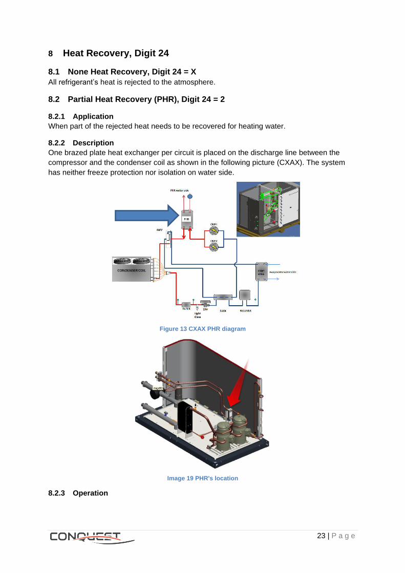
8.2.2 Description
One brazed plate heat exchanger per circuit is placed on the discharge line between the
compressor and the condenser coil as shown in the following picture (CXAX). The system
has neither freeze protection nor isolation on water side.
Figure 13 CXAX PHR diagram
Image 19 PHR's location
8.2.3 Operation

24 | P a g e
At the discharge line of the compressor, refrigerant is de-superheated by transferring its
sensible heat to the water which will rise its temperature. At full load conditions (PHR EWT=
40°C / LWT=45°C - OAT = 35°C - EVAP EWT= 12°C / LWT= 7°C), 20% of the cooling
capacity can be recovered.
Figure 14 PHR’s Operating map
Even if the heat exchanger has on site water connections, the customer shall provide the
water loop for partial heat recovery; that means: a circulation pump provides constant
water flow rate from the tank; three-way valve to adjust the water flow of PHR heat
exchanger based on the heat exchanger leaving water temperature (As the leaving water
temperature increases, the PHR water flow rate increases) and safety elements such as
expansion tanks and safety valves
Figure 15 Customer's connection diagram
8.2.4 Benefits
- Recuperation of part of the heating rejected capacity.
- Energy saving
25 | P a g e
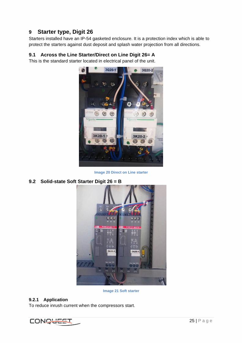
9 Starter type, Digit 26 Starters installed have an IP-54 gasketed enclosure. It is a protection index which is able to
protect the starters against dust deposit and splash water projection from all directions.
9.1 Across the Line Starter/Direct on Line Digit 26= A
This is the standard starter located in electrical panel of the unit.
Image 20 Direct on Line starter
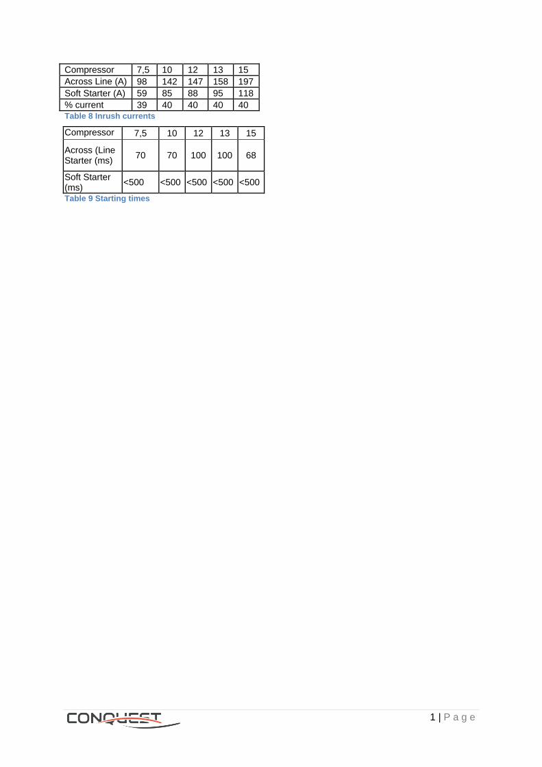
9.2 Solid-state Soft Starter Digit 26 = B
Image 21 Soft starter
9.2.1 Application
To reduce inrush current when the compressors start.

26 | P a g e
9.2.2 Description
Factory-installed, located in electrical panel of the unit.
9.2.3 Operation
- In this circuit, the soft starter replaces the direct on line starter.
- It controls the current flow which will generate the compressors to start gradually.
9.2.4 Benefits
- With the soft starter, the starting current drops down to 2.5 - 3 IN (IN: nominal
intensity).
- The compressor can start smoothly as the starting current is reduced.
- Smooth starting reduces motor and compressor wear.
- Less stress on the power supply.
9.2.5 Incompatibilities
Direct on Line.
9.2.6 More detail
There is a device called Silicon Controlled Rectifier (SCR) that soft starter works with. The
SCR is an electronic switch which allows current to flow through it only when electronic signal
is applied to its gate.
Comparison between across line starter and soft starter:
By installing soft starter in the circuit, it will reduce the starting current. There are 5 different
sizes of compressor.
1 | P a g e
Compressor size
7,5 10 12 13 15
Across Line (A) (()Starter (A)
98 142 147 158 197
Soft Starter (A) 59 85 88 95 118
% current reduction
39 40 40 40 40 Table 8 Inrush currents
Compressor size
7,5 10 12 13 15
Across (Line Starter (ms)
70 70 100 100 68
Soft Starter (ms)
<500 <500 <500 <500 <500
Table 9 Starting times
25 | P a g e
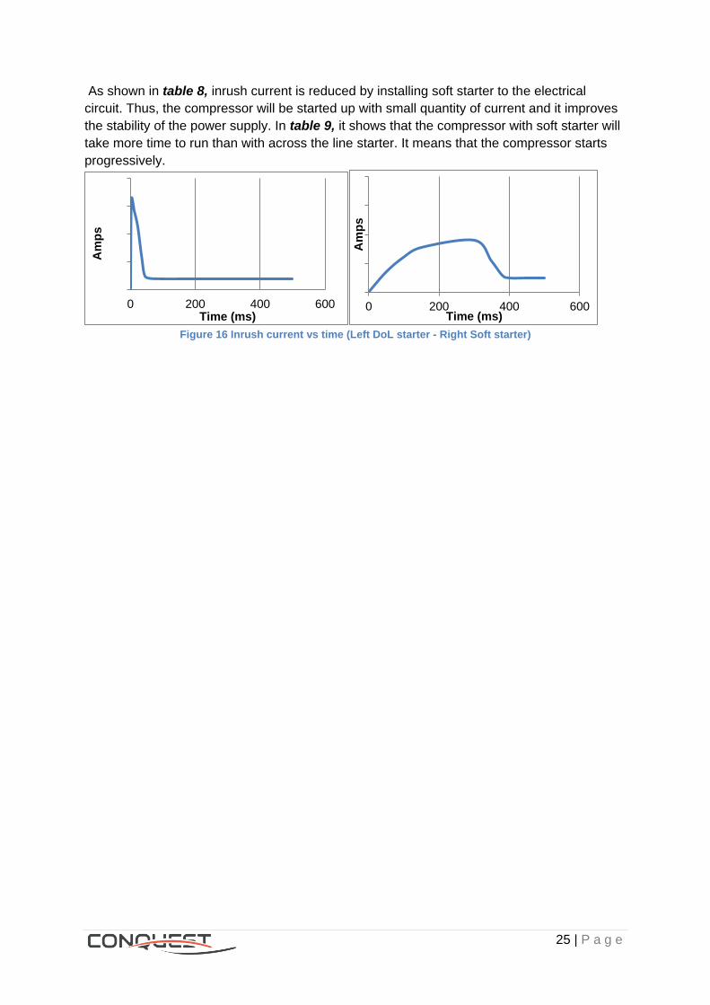
As shown in table 8, inrush current is reduced by installing soft starter to the electrical
circuit. Thus, the compressor will be started up with small quantity of current and it improves
the stability of the power supply. In table 9, it shows that the compressor with soft starter will
take more time to run than with across the line starter. It means that the compressor starts
progressively.
Figure 16 Inrush current vs time (Left DoL starter - Right Soft starter)
0 200 400 600
Am
ps
Time (ms) 0 200 400 600
Am
ps
Time (ms)

26 | P a g e
10 Human interface, Digit 30
The human interface will let the operator control chiller’s water set points, scheduling,
enable/disable options, etc…
Figure 17 Control architecture
10.1 Without interface, Digit 30= X For starting the chiller it’s necessary to have an interface even if the chiller was ordered
without it. The customer won’t have any information of chiller’s operation except if it’s
connected to BMS. Also only remote ON/OFF would be possible.
10.2 Interface PGD1, Digit 30= A
10.2.1 Description
This panel has a greyscale display, for programing the chiller and view operation values.
For details, see CH535 user guide.
Image 22 PGD1 Interface
10.3 Interface PGDTouch , Digit 30 = B
10.3.1 Description
Hum
an inte
rface
PD
G1 o
r P
DG
Touch

27 | P a g e
This interface counts with a full color touch display to ease chiller’s controlling. Besides
showing the operation values and letting control the chiller, it is also possible view an
historical report of the operation.
Image 23 PDG Touch interface
Image 24 PDG Touch sample interface
10.3.2 Benefits
Friendly user interface.
28 | P a g e
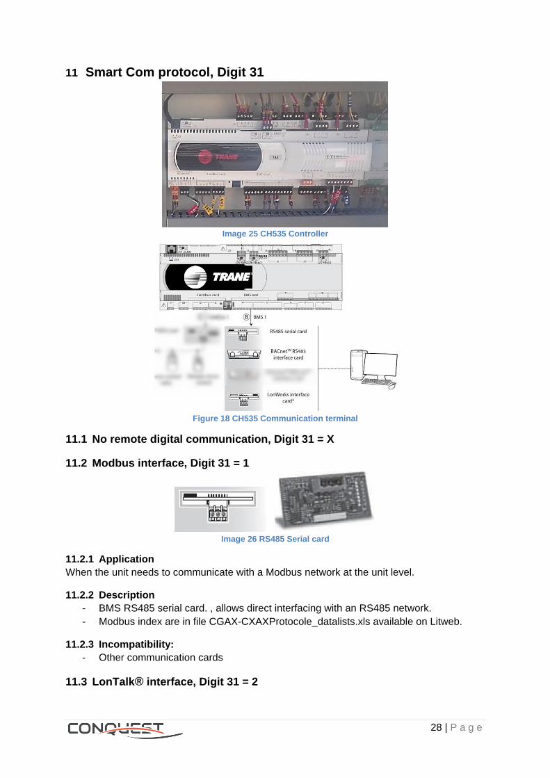
11 Smart Com protocol, Digit 31
Image 25 CH535 Controller
Figure 18 CH535 Communication terminal
11.1 No remote digital communication, Digit 31 = X
11.2 Modbus interface, Digit 31 = 1
Image 26 RS485 Serial card
11.2.1 Application
When the unit needs to communicate with a Modbus network at the unit level.
11.2.2 Description
- BMS RS485 serial card. , allows direct interfacing with an RS485 network.
- Modbus index are in file CGAX-CXAXProtocole_datalists.xls available on Litweb.
11.2.3 Incompatibility:
- Other communication cards
11.3 LonTalk® interface, Digit 31 = 2
29 | P a g e
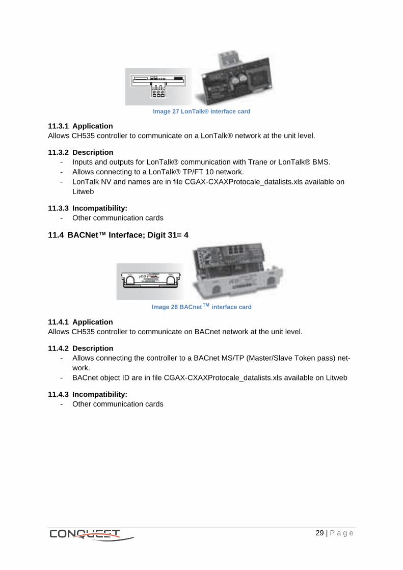
Image 27 LonTalk® interface card
11.3.1 Application
Allows CH535 controller to communicate on a LonTalk® network at the unit level.
11.3.2 Description
- Inputs and outputs for LonTalk® communication with Trane or LonTalk® BMS.
- Allows connecting to a LonTalk® TP/FT 10 network.
- LonTalk NV and names are in file CGAX-CXAXProtocale_datalists.xls available on
Litweb
11.3.3 Incompatibility:
- Other communication cards
11.4 BACNet™ Interface; Digit 31= 4
Image 28 BACnet™ interface card
11.4.1 Application
Allows CH535 controller to communicate on BACnet network at the unit level.
11.4.2 Description
- Allows connecting the controller to a BACnet MS/TP (Master/Slave Token pass) net-
work.
- BACnet object ID are in file CGAX-CXAXProtocale_datalists.xls available on Litweb
11.4.3 Incompatibility:
- Other communication cards
30 | P a g e
12 External customer input/output option, Digit 32
12.1 Without, Digit 32 = X
12.2 With, Digit 32 = A
12.2.1 Package included:
Customer inputs:
Auxiliary Set point validation.
External water Set point*.
External current demand limit Set point
Customer outputs:
Programmable relays (x4)
12.2.2 Relay costumer information
For more details, Refer to table 22 of the IOM
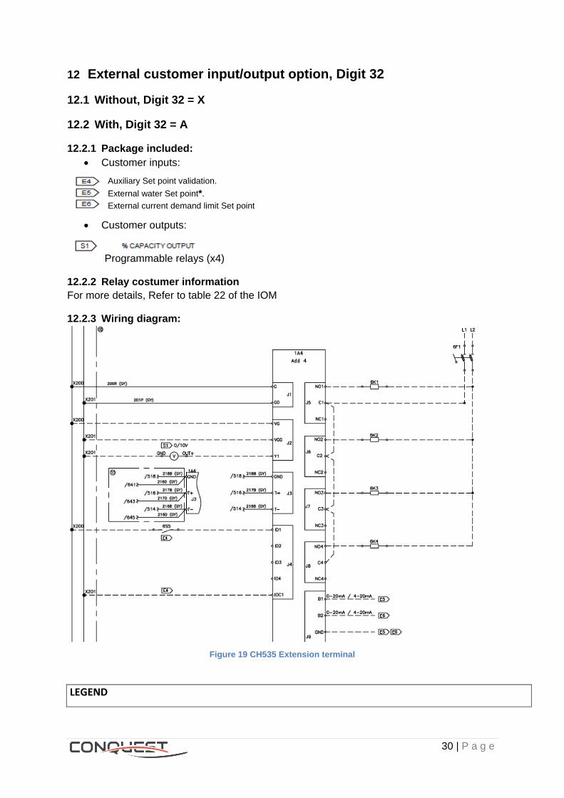
12.2.3 Wiring diagram:
Figure 19 CH535 Extension terminal
LEGEND
31 | P a g e
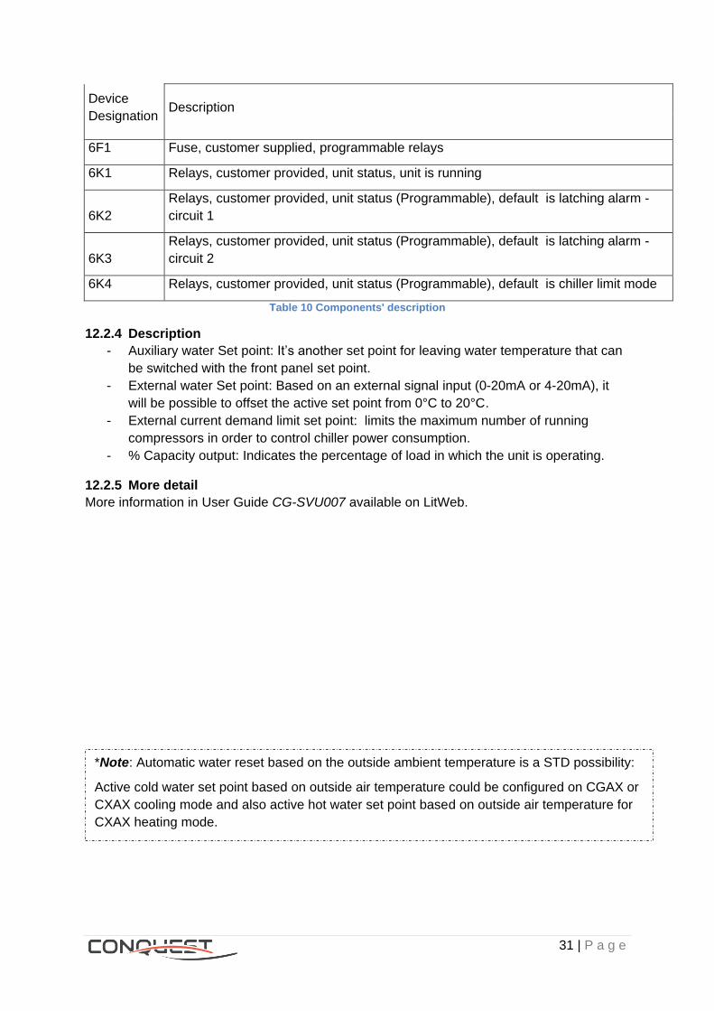
Device
Designation Description
6F1 Fuse, customer supplied, programmable relays
6K1 Relays, customer provided, unit status, unit is running
6K2
Relays, customer provided, unit status (Programmable), default is latching alarm -
circuit 1
6K3
Relays, customer provided, unit status (Programmable), default is latching alarm -
circuit 2
6K4 Relays, customer provided, unit status (Programmable), default is chiller limit mode
Table 10 Components' description
12.2.4 Description
- Auxiliary water Set point: It’s another set point for leaving water temperature that can
be switched with the front panel set point.
- External water Set point: Based on an external signal input (0-20mA or 4-20mA), it
will be possible to offset the active set point from 0°C to 20°C.
- External current demand limit set point: limits the maximum number of running
compressors in order to control chiller power consumption.
- % Capacity output: Indicates the percentage of load in which the unit is operating.
12.2.5 More detail
More information in User Guide CG-SVU007 available on LitWeb.
*Note: Automatic water reset based on the outside ambient temperature is a STD possibility:
Active cold water set point based on outside air temperature could be configured on CGAX or
CXAX cooling mode and also active hot water set point based on outside air temperature for
CXAX heating mode.

32 | P a g e
13 Smart Sequencer, Digit 33
13.1 Without, Digit 33 = X
13.2 With Smart Sequencer, Digit 33 = 1
13.2.1 Application
To control up to 3 chillers of equal capacity in parallel configuration.
Figure 20 Parallel Units configuration
13.2.2 Description
The system will activate in cascade each of the chillers, it means that the chiller will be
activated once the previous have reached its full charge. The chillers communicate between
them by pLan Link.
Figure 21 Operating representation
13.2.3 Operation
33 | P a g e
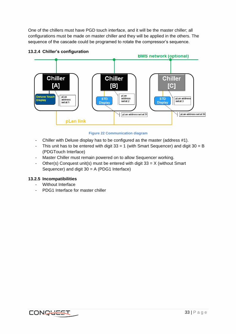
One of the chillers must have PGD touch interface, and it will be the master chiller; all
configurations must be made on master chiller and they will be applied in the others. The
sequence of the cascade could be programed to rotate the compressor’s sequence.
13.2.4 Chiller’s configuration
Figure 22 Communication diagram
- Chiller with Deluxe display has to be configured as the master (address #1).
- This unit has to be entered with digit 33 = 1 (with Smart Sequencer) and digit 30 = B
(PDGTouch Interface)
- Master Chiller must remain powered on to allow Sequencer working.
- Other(s) Conquest unit(s) must be entered with digit 33 = X (without Smart
Sequencer) and digit 30 = A (PDG1 Interface)
13.2.5 Incompatibilities
- Without Interface
- PDG1 Interface for master chiller
34 | P a g e
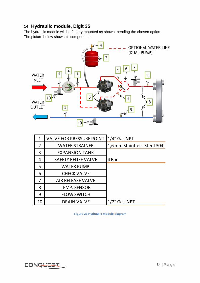
14 Hydraulic module, Digit 35 The hydraulic module will be factory mounted as shown, pending the chosen option.
The picture below shows its components:
Figure 23 Hydraulic module diagram
1 VALVE FOR PRESSURE POINT 1/4" Gas NPT
2 WATER STRAINER 1,6 mm Staintless Steel 304
3 EXPANSION TANK
4 SAFETY RELIEF VALVE 4 Bar
5 WATER PUMP
6 CHECK VALVE
7 AIR RELEASE VALVE
8 TEMP. SENSOR
9 FLOW SWITCH
10 DRAIN VALVE 1/2" Gas NPT
35 | P a g e
14.1 No pumps and no contactors, Digit 35 = X
Hydraulic module is not integrated in the unit; the costumer provides pump and pump’s
electrical systems.
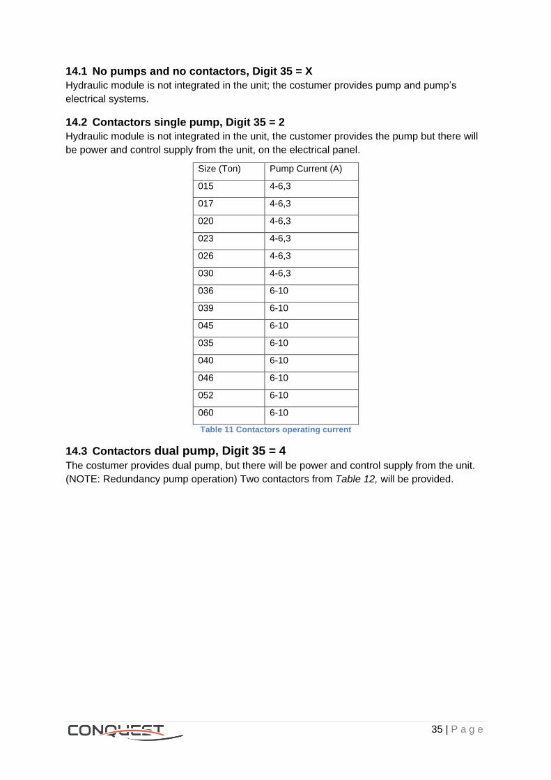
14.2 Contactors single pump, Digit 35 = 2 Hydraulic module is not integrated in the unit, the customer provides the pump but there will
be power and control supply from the unit, on the electrical panel.
Size (Ton) Pump Current (A)
015 4-6,3
017 4-6,3
020 4-6,3
023 4-6,3
026 4-6,3
030 4-6,3
036 6-10
039 6-10
045 6-10
035 6-10
040 6-10
046 6-10
052 6-10
060 6-10
Table 11 Contactors operating current
14.3 Contactors dual pump, Digit 35 = 4 The costumer provides dual pump, but there will be power and control supply from the unit.
(NOTE: Redundancy pump operation) Two contactors from Table 12, will be provided.

36 | P a g e
14.4 Single pump standard pressure, Digit 35 = 5
14.4.1 Application
Simplifies installation of the unit.
14.4.2 Description
Image 29 Single pump hydraulic module
- The supplier is Grundfos.
- The pump is integrated into unit’s hydraulic module.
14.4.3 Pump reference:
Pumps available:
CGAX / CXAX STD Pressure Sizes Pump
015 AC 25-109
017 AC 25-109
020 AC 25-109
023 AC 25-116
026 AC 25-116
030 AC 25-116
036 AC 25-116
039 AC 25-125
045 AC 25-125
035 AC 25-116
040 AC 25-125
046 AC 25-125
052 AC 25-125
060 AC 25-125 Table 12 Standard head available pumps
14.4.4 Operation / Benefits
AC 25 - 109 Size of the pump
case Diameter of the impeller
(mm)
37 | P a g e
- Compact design: Pump and motor are integrated in a compact and user-friendly
design, the pump is fitted to a low-profile base plate, making it ideal for installation in
systems.
- High reliability: State-of-the-art mechanical shaft seal design and materials offering
high wear resistance and long operative life. Also the pumps are less sensitive to
impurities in the pumped liquid.
- Low noise level: The AC pumps offer very silent operation.
14.4.5 Material specification
Description Material Material
EN ISO/AISI/ASTM
Pump housing Composite PP 30 % GF
Impeller Composite, brass Table 13 Material specification
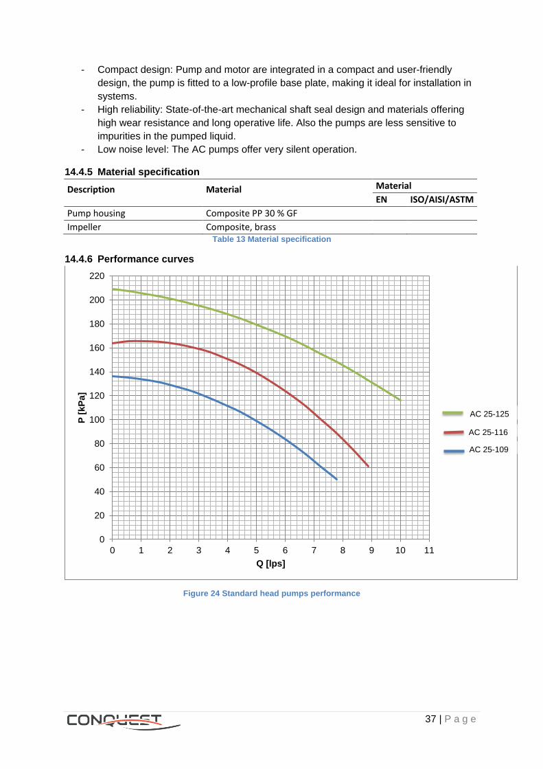
14.4.6 Performance curves
Figure 24 Standard head pumps performance
0
20
40
60
80
100
120
140
160
180
200
220
0 1 2 3 4 5 6 7 8 9 10 11
P [
kP
a]
Q [lps]
AC 25-109
AC 25-116
AC 25-125

38 | P a g e
14.4.7 Electrical data
Pump type P1 [kW] P2 [kW] IN [A] Cos ϕ1/1 n1/1 [min-1]
AC 25-109 1,20 0,87 2,44 0,75 2838
AC 25-116 1,50 1,26 3,5 0,72 2892
AC 25-125 2,30 1,90 5,03 0,78 2863
Table 14 Standard head pumps electrical data
14.5 Single pump high pressure, Digit 35 = 6
14.5.1 Application
When the requested available pressure is not archived by the standard pressure pumps.
14.5.2 Description
Pumps available:
CGAX / CXAX High Pressure Sizes Pump
015 AC 25-125
017 AC 25-125
020 AC 25-125
023 AC 25-125
026 AC 25-125
030 AC 25-125
036 AC 30-142
039 AC 30-142
045 AC 30-142
035 AC 30-142
040 AC 30-142
046 AC 30-142
052 AC 30-142
060 AC 30-142 Table 15 High head available pumps
14.5.3 Operation / Benefits
Same as single pump standard pressure.
14.5.4 Material specification
Same as single pump standard pressure.

39 | P a g e
14.5.5 Performance curves
Figure 25 High head pumps performance
14.5.6 Electrical data
Pump type P1 [kW] P2 [kW] IN [A] Cos ϕ1/1 n1/1 [min-1] AC 30 3,00 2,56 6,20 0,78 2865
Table 16 High head pumps electrical data
14.6 Dual pump standard pressure, Digit 35 = 7
Image 30 Dual pump hydraulic module
14.6.1 Application
Guard pump for increasing reliability of the water circulation
14.6.2 Description
Just one of the pumps works at the time, the other is in stand-by but in case there is a failure
on the active pump the other will take the place automatically.
14.6.3 Dual pump high pressure, Digit 35 = 8
It’s the same but uses the high pressure single pump.
0
30
60
90
120
150
180
210
240
270
0 1 2 3 4 5 6 7 8 9 10 11
P [
kP
a]
Q [lps]
A…AC 30-142
40 | P a g e
15 Smart Flow Control, Digit 36
15.1 No pump flow control; Digit 36 = X
The pump will always work at its nominal speed and the customer will have to use balancing
valves to adjust the operation point.
15.2 Manual flow control, Digit 36 = B
15.2.1 Application
The goal of this alternative is to provide appropriate flow rate and hydraulic balance, without
the need of mechanical balancing valve, but, taking advantage of the energy consumption
optimization of the pump.
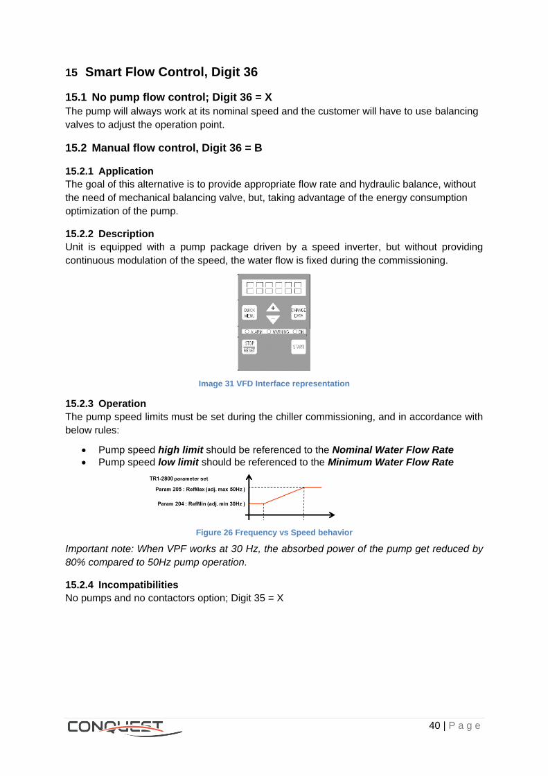
15.2.2 Description
Unit is equipped with a pump package driven by a speed inverter, but without providing
continuous modulation of the speed, the water flow is fixed during the commissioning.
Image 31 VFD Interface representation
15.2.3 Operation
The pump speed limits must be set during the chiller commissioning, and in accordance with
below rules:
Pump speed high limit should be referenced to the Nominal Water Flow Rate
Pump speed low limit should be referenced to the Minimum Water Flow Rate
Figure 26 Frequency vs Speed behavior
Important note: When VPF works at 30 Hz, the absorbed power of the pump get reduced by
80% compared to 50Hz pump operation.
15.2.4 Incompatibilities
No pumps and no contactors option; Digit 35 = X
41 | P a g e
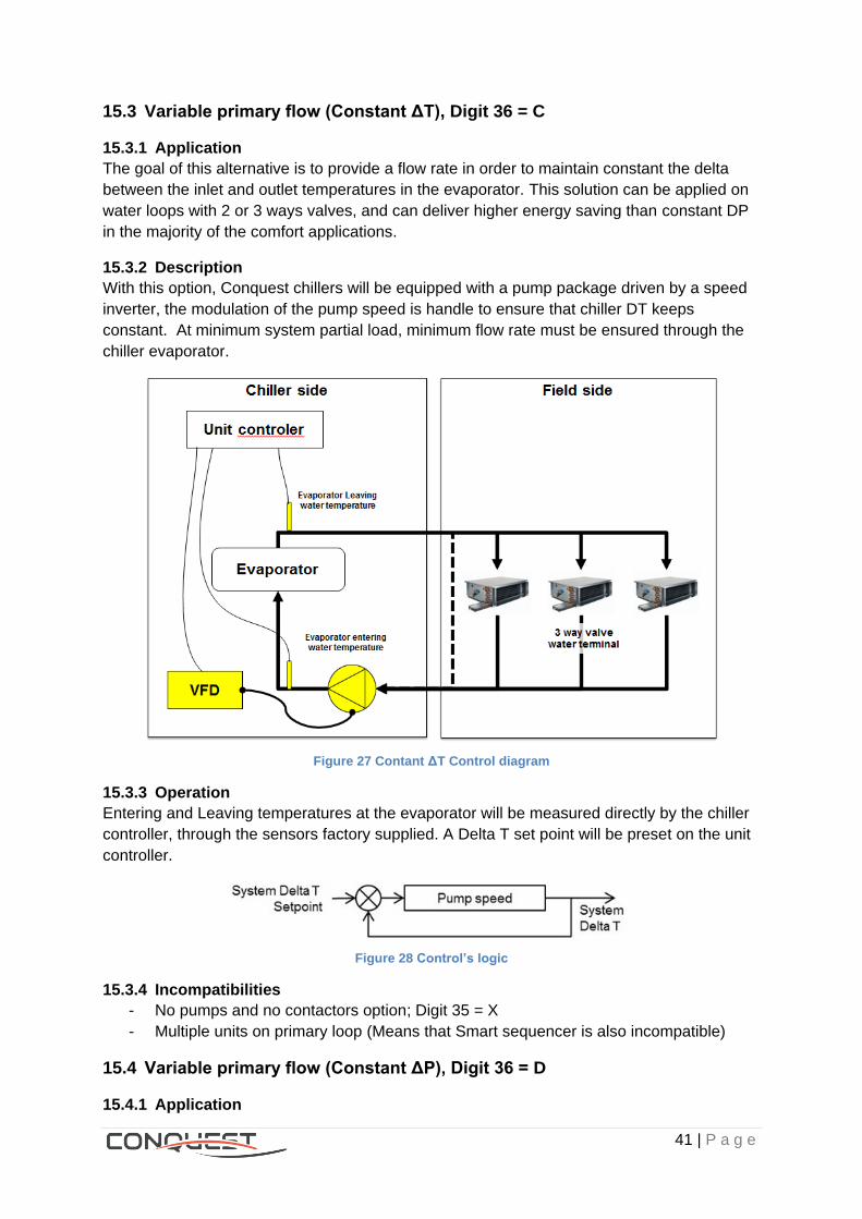
15.3 Variable primary flow (Constant ΔT), Digit 36 = C
15.3.1 Application
The goal of this alternative is to provide a flow rate in order to maintain constant the delta
between the inlet and outlet temperatures in the evaporator. This solution can be applied on
water loops with 2 or 3 ways valves, and can deliver higher energy saving than constant DP
in the majority of the comfort applications.
15.3.2 Description
With this option, Conquest chillers will be equipped with a pump package driven by a speed
inverter, the modulation of the pump speed is handle to ensure that chiller DT keeps
constant. At minimum system partial load, minimum flow rate must be ensured through the
chiller evaporator.
Figure 27 Contant ΔT Control diagram
15.3.3 Operation
Entering and Leaving temperatures at the evaporator will be measured directly by the chiller
controller, through the sensors factory supplied. A Delta T set point will be preset on the unit
controller.
Figure 28 Control’s logic
15.3.4 Incompatibilities
- No pumps and no contactors option; Digit 35 = X
- Multiple units on primary loop (Means that Smart sequencer is also incompatible)
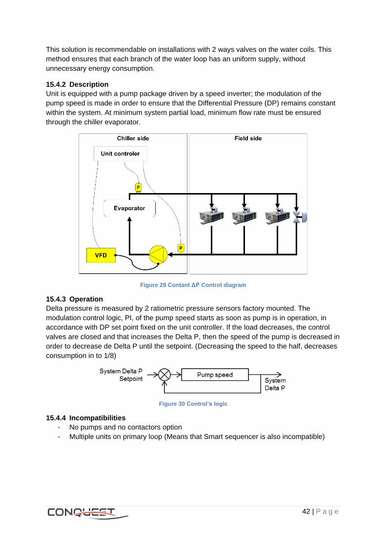
15.4 Variable primary flow (Constant ΔP), Digit 36 = D
15.4.1 Application
42 | P a g e
This solution is recommendable on installations with 2 ways valves on the water coils. This
method ensures that each branch of the water loop has an uniform supply, without
unnecessary energy consumption.
15.4.2 Description
Unit is equipped with a pump package driven by a speed inverter; the modulation of the
pump speed is made in order to ensure that the Differential Pressure (DP) remains constant
within the system. At minimum system partial load, minimum flow rate must be ensured
through the chiller evaporator.
Figure 29 Contant ΔP Control diagram
15.4.3 Operation
Delta pressure is measured by 2 ratiometric pressure sensors factory mounted. The
modulation control logic, PI, of the pump speed starts as soon as pump is in operation, in
accordance with DP set point fixed on the unit controller. If the load decreases, the control
valves are closed and that increases the Delta P, then the speed of the pump is decreased in
order to decrease de Delta P until the setpoint. (Decreasing the speed to the half, decreases
consumption in to 1/8)
Figure 30 Control’s logic
15.4.4 Incompatibilities
- No pumps and no contactors option
- Multiple units on primary loop (Means that Smart sequencer is also incompatible)

43 | P a g e
16 Buffer tank, Digit 37
16.1 Without Buffer tank; Digit 37 = X
16.2 Buffer Tank, Digit 37 = 1
16.2.1 Application
- Used to increase water chiller inertia
- Allows to meet the two minutes water loop circulation
- Stable water temperature operation
16.2.2 Description/Operation
- Consists in a tank of water placed before the pump, Factory-installed
- Placed below the unit structure
- It doesn’t modifies unit dimensions but the height increases +330mm
Image 32 Unit w/o buffer tank & with it
Image 33 Buffer tank & Hydraulic module
16.2.3 Volumes
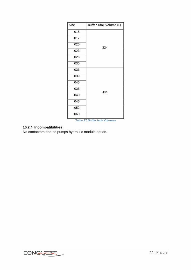
44 | P a g e
Size Buffer Tank Volume (L)
015
324
017
020
023
026
030
036
444
039
045
035
040
046
052
060
Table 17 Buffer tank Volumes
16.2.4 Incompatibilities
No contactors and no pumps hydraulic module option.
45 | P a g e
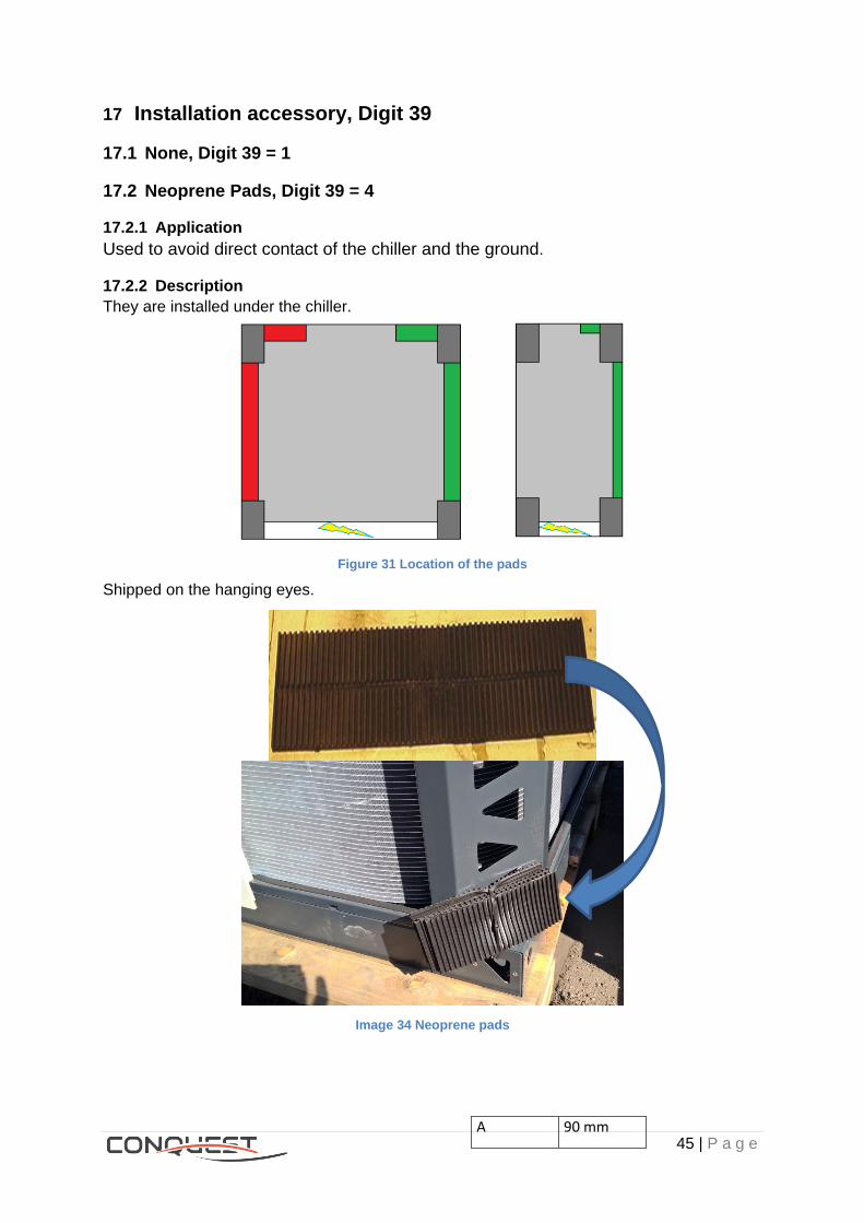
17 Installation accessory, Digit 39
17.1 None, Digit 39 = 1
17.2 Neoprene Pads, Digit 39 = 4
17.2.1 Application
Used to avoid direct contact of the chiller and the ground.
17.2.2 Description
They are installed under the chiller.
Figure 31 Location of the pads
Shipped on the hanging eyes.
Image 34 Neoprene pads
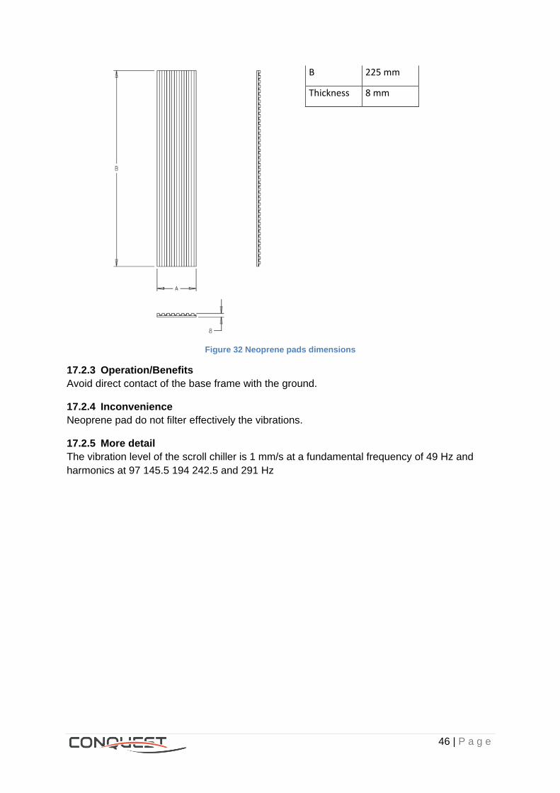
A 90 mm
46 | P a g e
Figure 32 Neoprene pads dimensions
17.2.3 Operation/Benefits
Avoid direct contact of the base frame with the ground.
17.2.4 Inconvenience
Neoprene pad do not filter effectively the vibrations.
17.2.5 More detail
The vibration level of the scroll chiller is 1 mm/s at a fundamental frequency of 49 Hz and
harmonics at 97 145.5 194 242.5 and 291 Hz
B 225 mm
Thickness 8 mm

47 | P a g e
18 Acoustic level, Digit 41
CGAX/CXAX
Noise Level
Digit 41
SIMPLEX
015/017/020/023/026/030
SIMPLEX LARGE
036/039/045
DUPLEX
035/040/046/052/060
SN (D41=3)
LN (D41=4)
HESP
(D41=2)
Table 18 CONQUEST's aspect depending on acoustic level
18.1 Standard Noise (SN), digit 15 = X
18.1.1 Application
When the unit is requested for a non-noise sensitive area.
18.1.2 Description
The fans are placed below the roof.
18.1.3 Operation
The chiller operates with a sound power level in between 83 to 89 dB(A)
18.2 Low Noise (LN), digit 15 = L
18.2.1 Application
When the unit is requested for a noise sensitive area.
48 | P a g e
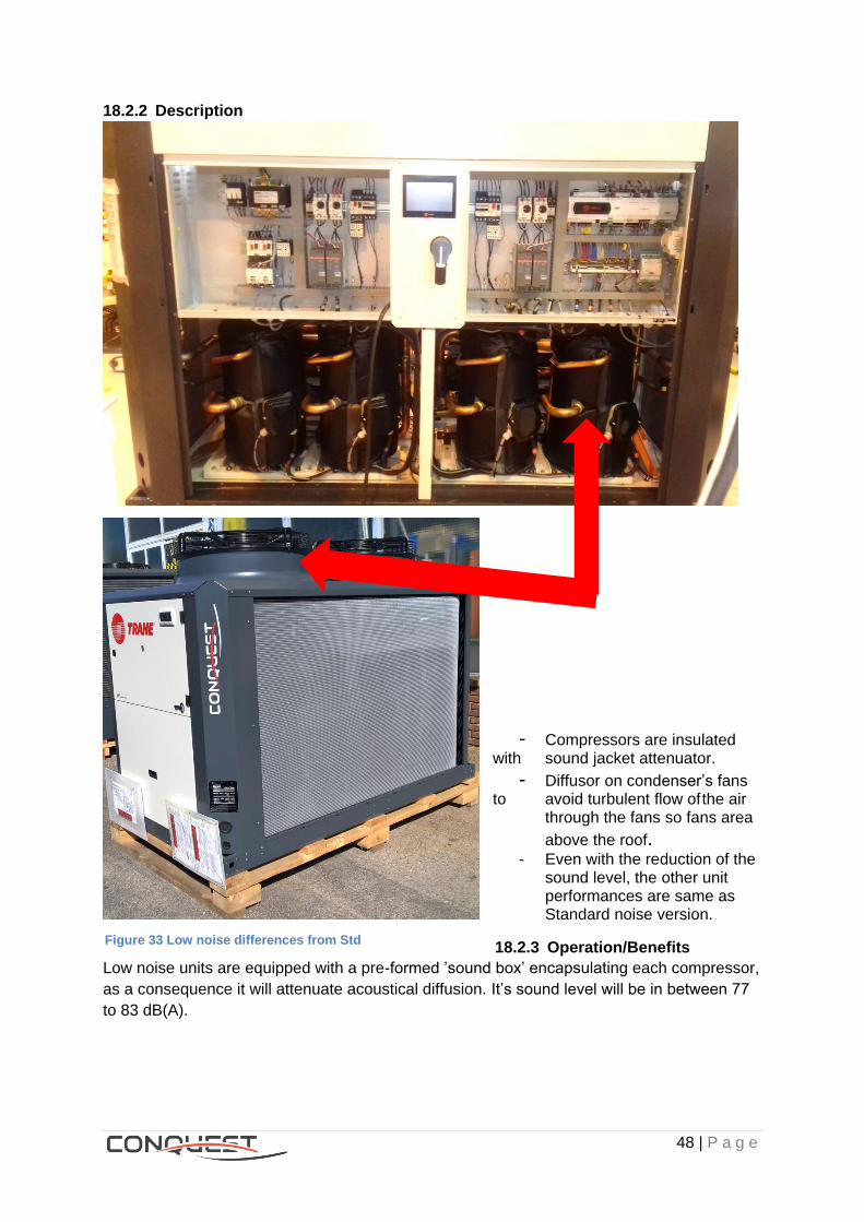
18.2.2 Description
- Compressors are insulated with sound jacket attenuator.
- Diffusor on condenser’s fans to avoid turbulent flow of the air through the fans so fans area
above the roof. - Even with the reduction of the
sound level, the other unit performances are same as Standard noise version.
18.2.3 Operation/Benefits
Low noise units are equipped with a pre-formed ’sound box’ encapsulating each compressor,
as a consequence it will attenuate acoustical diffusion. It’s sound level will be in between 77
to 83 dB(A).
Figure 33 Low noise differences from Std
49 | P a g e
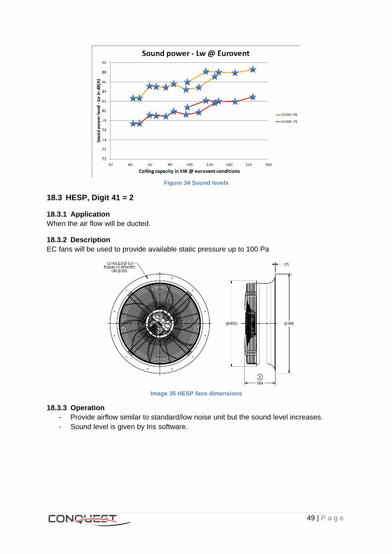
Figure 34 Sound levels
18.3 HESP, Digit 41 = 2
18.3.1 Application
When the air flow will be ducted.
18.3.2 Description
EC fans will be used to provide available static pressure up to 100 Pa
Image 35 HESP fans dimensions
18.3.3 Operation
- Provide airflow similar to standard/low noise unit but the sound level increases.
- Sound level is given by Iris software.
50 | P a g e
19 Condenser protection, Digit 42
19.1 No option, Digit 42 = X
19.2 Condenser guard grill, Digit 42 = A
19.2.1 Application
The unit is requested for polluted, susceptible to be damaged or a persons’ high frequency
areas.
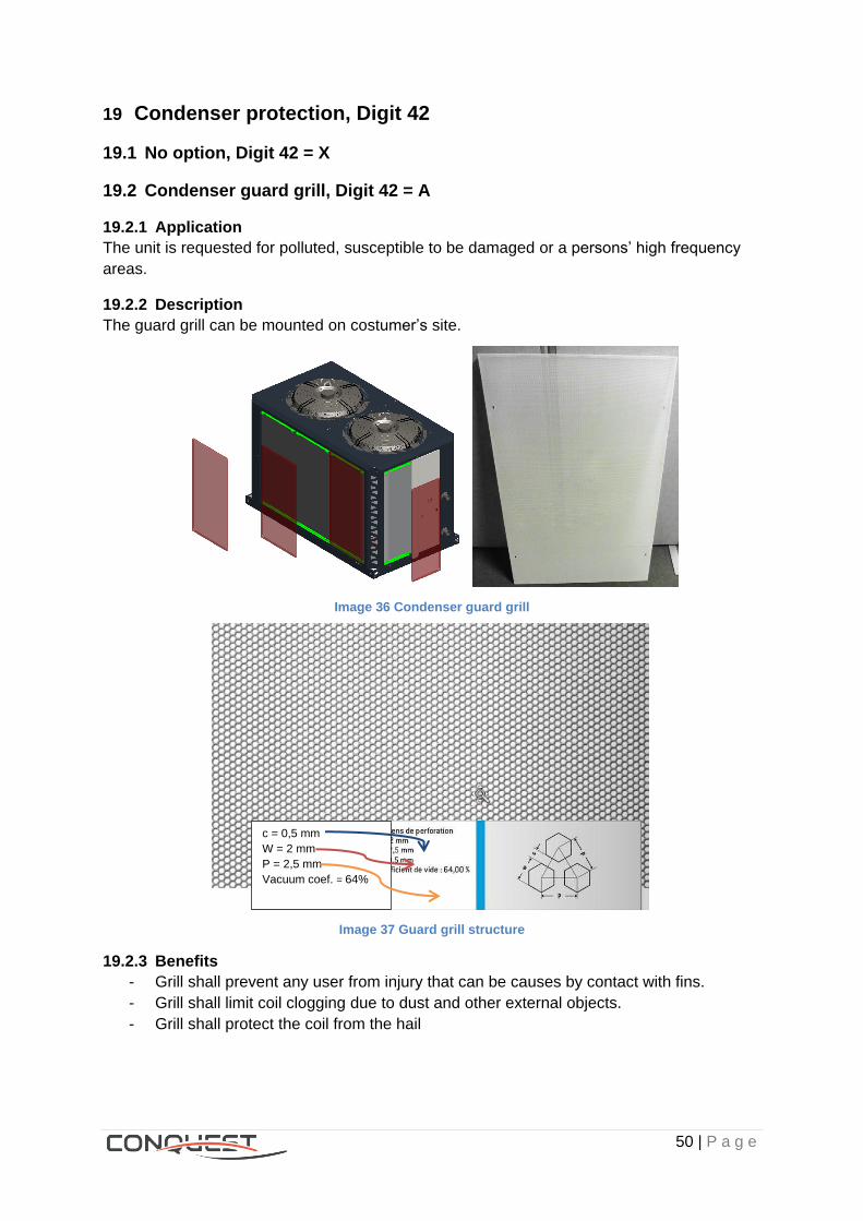
19.2.2 Description
The guard grill can be mounted on costumer’s site.
Image 36 Condenser guard grill
Image 37 Guard grill structure
19.2.3 Benefits
- Grill shall prevent any user from injury that can be causes by contact with fins.
- Grill shall limit coil clogging due to dust and other external objects.
- Grill shall protect the coil from the hail
c = 0,5 mm
W = 2 mm
P = 2,5 mm
Vacuum coef. = 64%
51 | P a g e
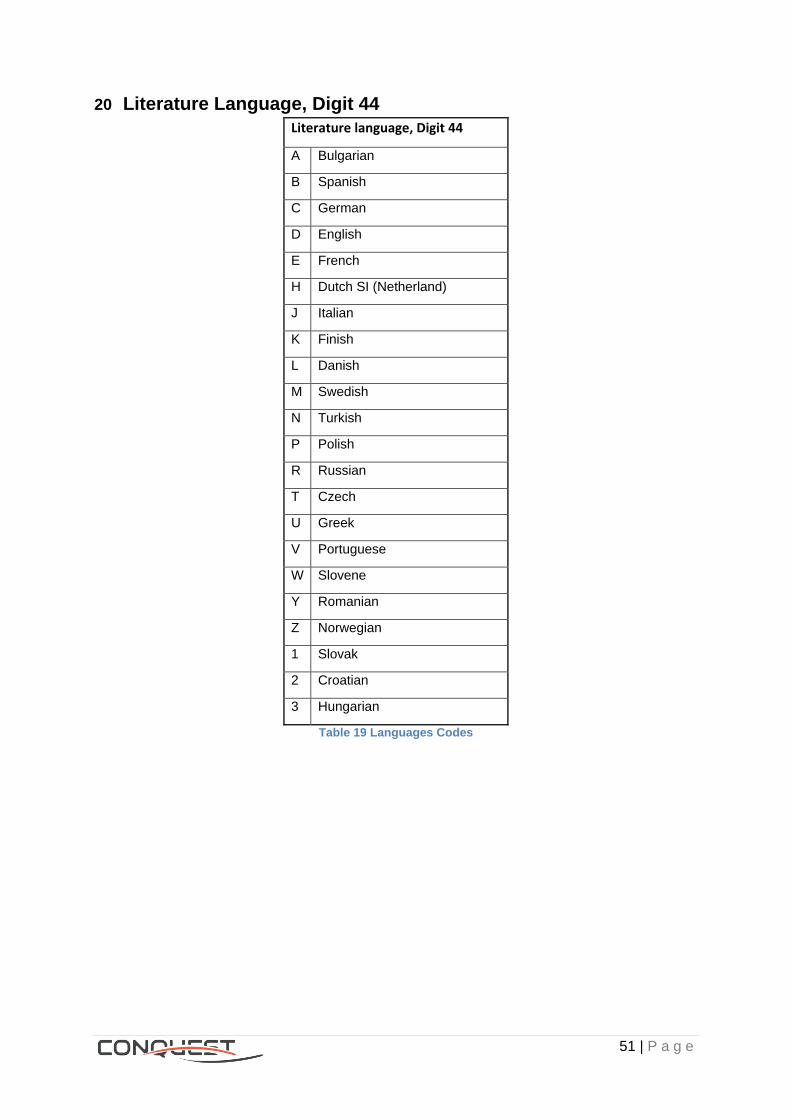
20 Literature Language, Digit 44
Literature language, Digit 44
A Bulgarian
B Spanish
C German
D English
E French
H Dutch SI (Netherland)
J Italian
K Finish
L Danish
M Swedish
N Turkish
P Polish
R Russian
T Czech
U Greek
V Portuguese
W Slovene
Y Romanian
Z Norwegian
1 Slovak
2 Croatian
3 Hungarian
Table 19 Languages Codes

52 | P a g e
21 Under/over voltage protection, Digit 45
21.1 None, Digit 45 = X
21.2 Included, Digit 45 = 1
21.2.1 Application
A RM4 TR relay is used to control unit phase sequence and under/over voltage protection.
21.2.2 Description
- Factory installed, located in the control panel.
- Only one relay for each unit.
Image 38 RM4 TR Relay
21.2.3 Operation
- If any fault linked is detected, the compressor is stopped.
- Overvoltage and undervoltage detection (RM4TR):
o In normal operation, the relay is energized and LEDs U and R are lit.
o If the average of the three voltages between phases fluctuates outside the
range to be monitored, the output relay is de-energized.
- Overvoltage: the Red LED “> U” on
- Undervoltage: the Red LED “< U” on
21.2.4 Benefits
- All motors are fully protected.
- Relay RM4 TR provides a phase reversal protection and under/over voltage
protection
21.2.5 Summary
Phase reveral protection Under/over voltage protection
Compressors Fans (and pump) Compressors Fans (and pump)
CGAX - CXAX Digit 45 = X YES YES NO NO
CGAX - CXAX Digit 45 = 1 YES YES YES YES
Image 39 Available protections
R Yellow LED: Indicates the relay state. U Green LED: Indicates that the relay power supply is on. > U Red LED: Overvoltage fault. < U Red LED: Under voltage fault. P Red LED: Phase failure or phase
reversal.
53 | P a g e
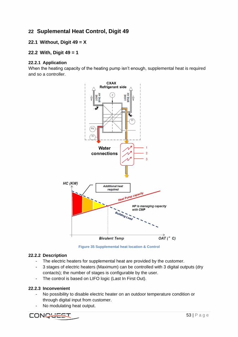
22 Suplemental Heat Control, Digit 49
22.1 Without, Digit 49 = X
22.2 With, Digit 49 = 1
22.2.1 Application
When the heating capacity of the heating pump isn’t enough, supplemental heat is required
and so a controller.
Figure 35 Supplemental heat location & Control
22.2.2 Description
- The electric heaters for supplemental heat are provided by the customer.
- 3 stages of electric heaters (Maximum) can be controlled with 3 digital outputs (dry
contacts); the number of stages is configurable by the user.
- The control is based on LIFO logic (Last In First Out).
22.2.3 Inconvenient
- No possibility to disable electric heater on an outdoor temperature condition or
through digital input from customer.
- No modulating heat output.

54 | P a g e
22.2.4 Incompatibilities
CGAX
23 Design Special, Digit 50
Lists .
Figures: Figure 1 CGAX & CXAX comparison ............................................................................................ 2
Figure 2 Frames' configuration ...................................................................................................... 3
Figure 6 Fans' distribution ............................................................................................................. 7
Figure 7 EC fans Pressure vs Airflow ............................................................................................ 8
Figure 8 AC fans Pressure vs Airflow ............................................................................................ 8
Figure 9 EC fans Power input vs Airflow ....................................................................................... 9
Figure 10 AC fans Power input vs Airflow ..................................................................................... 9
Figure 11 Operating map (air side) CGAX & CXAX SA Cooling mode ....................................... 10
Figure 12 Operating map CXAX SA Heating mode .................................................................... 11
Figure 13 Operating map CGAX & CXAX LA cooling mode ....................................................... 11
Figure 14 Pump activation Option’s system diagram .................................................................. 14
Figure 15 Conquest's operating map water side ......................................................................... 15
Figure 16 CXAX PHR diagram .................................................................................................... 23
Figure 17 PHR’s Operating map ................................................................................................. 24
Figure 18 Customer's connection diagram .................................................................................. 24
Figure 19 Inrush current vs time (Left Direct starter - Right Soft starter)..................................... 25
Figure 20 Control architecture ..................................................................................................... 26
Figure 21 CH535 Communication terminal ................................................................................. 28
Figure 22 CH535 Extension terminal .......................................................................................... 30
Figure 23 Parallel Units configuration ......................................................................................... 32
Figure 24 Operating representation ............................................................................................ 32
Figure 25 Communication diagram ............................................................................................. 33
Figure 26 Hydraulic module diagram .......................................................................................... 34
Figure 27 Standard head pumps performance ............................................................................ 37
Figure 28 High head pumps performance ................................................................................... 39
Figure 29 Frequency vs Speed behavior .................................................................................... 40
Figure 30 Contant ΔT Control diagram ....................................................................................... 41
Figure 31 Control’s logic .............................................................................................................. 41
Figure 32 Contant ΔP Control diagram ....................................................................................... 42
Figure 33 Control’s logic .............................................................................................................. 42
Figure 34 Neoprene pads dimensions ........................................................................................ 46
Figure 35 Low noise differences from Std ................................................................................... 48
Figure 36 Sound levels ................................................................................................................ 49
Figure 37 Supplemental heat location & Control ......................................................................... 53
Lists .
Images: Image 1 CONQUEST - Duplex frame - HESP .............................................................................. 4
Image 2 CONQUEST - Duplex frame - STD Noise ....................................................................... 4
Image 3 Unit Number plate ........................................................................................................... 4
Image 4 Unit w/o hydraulic module ............................................................................................... 5
Image 5 Unit with hydraulic module .............................................................................................. 5
Image 6 Electrical panel ................................................................................................................ 5
Image 7 AC fans model ................................................................................................................. 6
Image 8 EC fans model ................................................................................................................. 6
Image 9 BPHE's heater ............................................................................................................... 12
Image 10 Hydraulic module's heaters ......................................................................................... 12
Image 11 Buffer tank's heaters.................................................................................................... 13
Image 12 Grooved water connection .......................................................................................... 16
Image 13 Coupling and pipe stub ................................................................................................ 17
Image 14 Aluminum fins .............................................................................................................. 18
Image 15 Gold epoxy aluminum fins ........................................................................................... 19
Image 16 Micro Channel Heat Exchanger .................................................................................. 20
Image 17 MCHE's parts .............................................................................................................. 21
Image 18 E-Coated MCHE .......................................................................................................... 22
Image 19 PHR's location ............................................................................................................. 23
Image 20 Direct starter ................................................................................................................ 25
Image 21 Soft starter ................................................................................................................... 25
Image 22 PGD1 Interface ............................................................................................................ 26
Image 23 PDG Touch interface ................................................................................................... 27
Image 24 PDG Touch sample interface ...................................................................................... 27
Image 25 CH535 Controller ......................................................................................................... 28
Image 26 RS485 Serial card ....................................................................................................... 28
Image 27 LonTalk® interface card .............................................................................................. 29
Image 28 BACnet™ interface card .............................................................................................. 29
Image 29 Single pump hydraulic module .................................................................................... 36
Image 30 Dual pump hydraulic module ....................................................................................... 39
Image 31 VFD Interface representation ...................................................................................... 40
Image 32 Unit w/o buffer tank & with it ........................................................................................ 43
Image 33 Buffer tank & Hydraulic module ................................................................................... 43
Image 34 Neoprene pads ............................................................................................................ 45
Image 35 HESP fans dimmensions ............................................................................................. 49
Image 36 Condenser guard grill .................................................................................................. 50
Image 37 Guard grill structure ..................................................................................................... 50
Image 38 RM4 TR Relay ............................................................................................................. 52
Image 39 Available protections ................................................................................................... 52

Lists .
Tables: Table 1 CGAX Range .................................................................................................................... 1
Table 2 CXAX Range .................................................................................................................... 2
Table 3 Frame & Coil's type .......................................................................................................... 3
Table 4 Fans operation ................................................................................................................. 7
Table 5 CGAX & CXAX Operating points airside ........................................................................ 10
Table 6 CXAX Heating mode operational points ......................................................................... 10
Table 8 CGAX & CXAX Heaters' power on buffer tanks ............................................................. 13
Table 9 Inrush currents ................................................................................................................. 1
Table 10 Starting times ................................................................................................................. 1
Table 11 Components' description .............................................................................................. 31
Table 12 Contactors operating current ........................................................................................ 35
Table 13 Standard head available pumps ................................................................................... 36
Table 14 Material specification .................................................................................................... 37
Table 15 Standard head pumps electrical data ........................................................................... 38
Table 16 High head available pumps .......................................................................................... 38
Table 17 High head pumps electrical data .................................................................................. 39
Table 18 Buffer tank Volumes ..................................................................................................... 44
Table 19 CONQUEST's aspect depending on acoustic level ...................................................... 47
Table 20 Languages Codes ........................................................................................................ 51
Trane optimizes the performance of homes and buildings around the world. A business of Ingersoll Rand, the leader in
creating and sustaining safe, comfortable and energy efficient environments, Trane offers a broad portfolio of advanced
controls and HVAC systems, comprehensive building services, and parts.
For more information, visit www.Trane.com.
Trane has a policy of continuous product and product data improvement and reserves the right to change design and specifications without
notice.
© 2015 Trane All rights reserved
CG-PRC037-GB December 2015