Embed Size (px)
Citation preview

Atkins Version 1.0 | 18 December 2013
Options/Feasibility Study for the A23/A232 Fiveways Scheme
Transport for London
18 December 2013

Options/Feasibility Study for the A23/A232 Fiveways Scheme
Atkins Version 1.0 | 18 December 2013
Notice
This document and its contents have been prepared and are intended solely for Transport for London’s information and use in relation to the Options/feasibility study for the A23/A232 Fiveways scheme.
Atkins Highways & Transportation assumes no responsibility to any other party in respect of or arising out of or in connection with this document and/or its contents.
This document has 70 pages including the cover.
Document history
Job number: 5127130 Document ref: 5127130/FS/REP/001
Revision Purpose description Originated Checked Reviewed Authorised Date
- Draft issue 05/12/13
A Final Issue 19/12/13
Client signoff
Client Transport for London
Project Fiveways Junction Improvement
Document title Options/feasibility study for the A23/A232 Fiveways scheme
Job no. 5127130
Copy no.
Document reference
5127130/FS/REP/001 Rev A

Options/Feasibility Study for the A23/A232 Fiveways Scheme
Atkins Version 1.0 | 18 December 2013
Table of contents
Chapter Pages
Executive summary 5
1. Introduction 6 1.1. Client Brief 6 1.2. Aims of the Study 6 1.3. Background 6 1.4. Proposed Options 6
2. Existing Information 8 2.1. Location 8 2.2. Road Layout 8 2.3. Bridge Records 9 2.4. As Built Drawings 9 2.5. Health and Safety 9 2.6. Environment 9 2.7. Traffic 9 2.8. Accident Data 10 2.9. Statutory Undertakers Equipment 10 2.10. Network Rail Equipment / Geometry 10 2.11. Land Ownership 11 2.12. Geotechnical Information 11 2.13. Topographical Information 11 2.14. Drainage Details 11
3. General Design Constraints 12 3.1. Highways General Design Principles 12 3.2. Design Life 12 3.3. Design Speed 12 3.4. Cross Section 13 3.5. Horizontal Alignment 14 3.6. Vertical Alignment 16 3.7. Visibility 16 3.8. Loading 17 3.9. Vertical Clearance 17 3.10. Railway Lateral Clearance 17 3.11. Road Restraint Systems 17 3.12. Statutory Undertakers Equipment 18 3.13. Temporary Works/Traffic Management 18 3.14. Network Rail 21 3.15. Other Stakeholders 21 3.16. Architecture and Finishes 21
4. Highways Design Option Development 22 4.1. Existing Topography 22 4.2. Option 1 Parameters 23 4.3. Option 1A Parameters 26 4.4. Option 2 Parameters 29
5. Structural Design Option Development 30 5.1. Structural Attributes 30 5.2. Construction Sequence 33

Options/Feasibility Study for the A23/A232 Fiveways Scheme
Atkins Version 1.0 | 18 December 2013
5.3. Network Rail Consultation 33
6. Appraisal of Options 35 6.1. Description of Viable Options 35 6.2. Estimated Initial Capital Costs 44 6.3. Whole Life Costs 45 6.4. Outline Construction Programme 45 6.5. Key Risks 45 6.6. Departures from Standard 46 6.7. Advantages and Disadvantages 46
7. Health and Safety Considerations 50
8. Environmental Considerations 51 8.1. Potential Ecological Constraints 51 8.2. Environmental Management Plans 57
9. Conclusions 58
10. Recommendations 58
Appendices 59
Appendix A. Existing Bridge Record Information 60
Appendix B. Existing Statutory Undertaker’s Information 61
Appendix C. Drawings 62
Appendix D. Outline Design Programme 63
Appendix E. Outline Construction Programme 64
Appendix F. Project Risk Register 65
Appendix G. Designers’ Risk Assessment 66
Appendix H. Environmental Management Plans and Ecology Calendar 67
Appendix I. Topographical Survey Specification and Extent 68
Tables Table 3-1 Details of Proposed cross section 13 Table 3-2 Details of SSD for a 50kph urban design 16 Table 5-1 Information to be requested from Network Rail 34 Table 6-1 Construction Period and Railway Possessions 45
Figures Figure 2-1 Location Plan 8 Figure 3-1 Extract from TD 9/93 showing geometric parameters for a 50kph design speed 15 Figure 3-2 Typical Reinforced concrete H4a Parapet 18 Figure 4-1 Extract from TD 41/95 of a simple layout for a private access 24 Figure 4-2 Diverge Slip Road layouts 25 Figure 4-3 Diverge Slip Road dimensions 25 Figure 4-4 Merge Slip Road layouts 27 Figure 4-5 Merge Slip Road dimensions 27 Figure 4-6 TD 27/05 Slip Road Cross Section Details 28 Figure 6-1 Existing South Abutment and central trestle showing clearance to track 37 Figure 6-2 Existing North Abutment and adjacent platform 37 Figure 6-3 High Meads loop Construction 39 Figure 6-4 River Worth Keighley Construction 39 Figure 6-5 Wooferton Bridge Construction 40 Figure 6-6 Typical Piling Rig Layout 40 Figure 6-7 View of Existing Waddon Bridge from the station 41
Options/Feasibility Study for the A23/A232 Fiveways Scheme
Atkins Version 1.0 | 18 December 2013
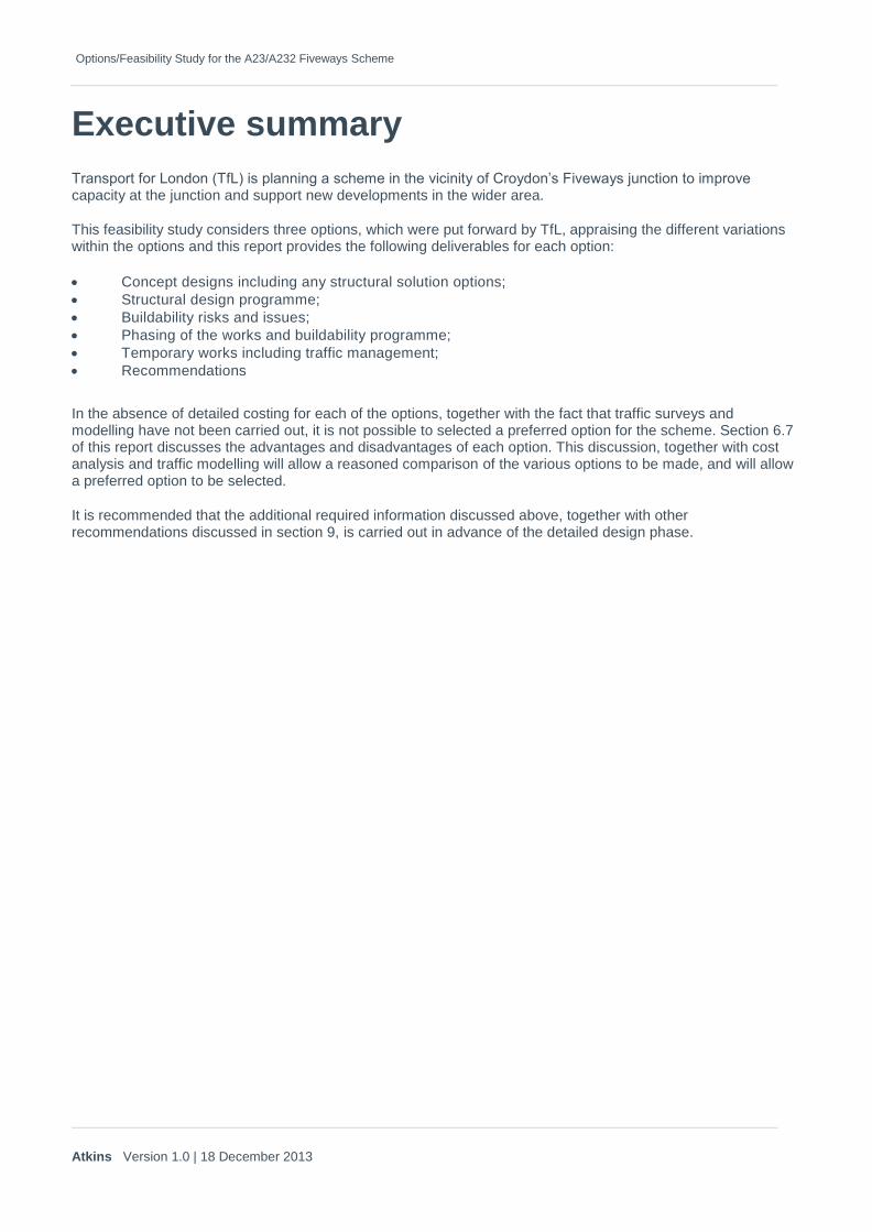
Executive summary
Transport for London (TfL) is planning a scheme in the vicinity of Croydon’s Fiveways junction to improve capacity at the junction and support new developments in the wider area.
This feasibility study considers three options, which were put forward by TfL, appraising the different variations within the options and this report provides the following deliverables for each option:
Concept designs including any structural solution options;
Structural design programme;
Buildability risks and issues;
Phasing of the works and buildability programme;
Temporary works including traffic management;
Recommendations
In the absence of detailed costing for each of the options, together with the fact that traffic surveys and modelling have not been carried out, it is not possible to selected a preferred option for the scheme. Section 6.7 of this report discusses the advantages and disadvantages of each option. This discussion, together with cost analysis and traffic modelling will allow a reasoned comparison of the various options to be made, and will allow a preferred option to be selected.
It is recommended that the additional required information discussed above, together with other recommendations discussed in section 9, is carried out in advance of the detailed design phase.
Options/Feasibility Study for the A23/A232 Fiveways Scheme
Atkins Version 1.0 | 18 December 2013
1. Introduction
1.1. Client Brief
Atkins has been commissioned by Transport for London (TfL) to undertake the feasibility study for the A23/A232 Fiveways scheme in accordance with its brief included in Tender Ref: tfl_scp_000027_task_24_co057.
1.2. Aims of the Study
As stated in the client brief, the objective of the feasibility study is to consider three options, which were put forward by TfL, appraising the different variations within the options. This report provides the following deliverables for each option:
Concept designs including any structural solution options;
Structural design programme;
Buildability risks and issues;
Phasing of the works and buildability programme;
Temporary works including traffic management;
Recommendations
1.3. Background Fiveways junction in Croydon is a signalised junction between a number of roads – the A23 Purley Way to the north and south, the A232 Stafford Road to the north east, the B275 Denning Avenue to the east and the B271 Stafford Road to the south west.
The junction is over-capacity, and traffic regularly builds up in the vicinity of the junction. The objective of the options proposed for this feasibility study is to alleviate the traffic feeding into the Fiveways junction.
1.4. Proposed Options The issues at Fiveways junction have been under investigation for some time, and TfL have developed two options to undertake feasibility and to undertake an analysis of the benefits of each option.
The options considered are as follows:
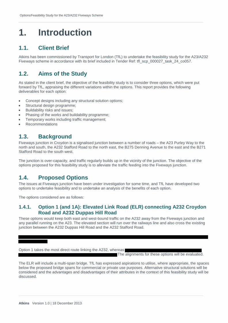
1.4.1. Option 1 (and 1A): Elevated Link Road (ELR) connecting A232 Croydon Road and A232 Duppas Hill Road
These options would keep both east and west-bound traffic on the A232 away from the Fiveways junction and any parallel running on the A23. The elevated section will run over the railways line and also cross the existing junction between the A232 Duppas Hill Road and the A232 Stafford Road.
Option 1 takes the most direct route linking the A232, whereas The alignments for these options will be evaluated.
The ELR will include a multi-span bridge. TfL has expressed aspirations to utilise, where appropriate, the spaces below the proposed bridge spans for commercial or private use purposes. Alternative structural solutions will be considered and the advantages and disadvantages of their attributes in the context of this feasibility study will be discussed.
Options/Feasibility Study for the A23/A232 Fiveways Scheme
Atkins Version 1.0 | 18 December 2013
1.4.2. Option 2: Waddon Bridge replacement and widening of Epsom Road for two-way traffic
This option proposes to replace the existing Waddon Station Bridge over the railway with a new replacement wider bridge.
This is intended to provide more carriageway lanes and allow more traffic capacity on this short critical link where it carries both A23 and A232 traffic.
Epsom Road is also proposed to be widened to allow a new two-way operation. This removes the need for Eastbound A232 traffic to use the Fiveways junction.

Options/Feasibility Study for the A23/A232 Fiveways Scheme
Atkins Version 1.0 | 18 December 2013
2. Existing Information
2.1. Location Fiveways junction in Croydon is a junction between a number of roads – the A23 Purley Way to the north and south, the A232 Stafford Road to the north east, the B275 Denning Avenue to the east and the B271 Stafford Road to the south west.
Figure 2-1 Location Plan
2.2. Road Layout
The A23 road runs north-south providing a link between the M25/M23 and Kennington Park/Oval. The A23 passes to the west of Croydon, adjacent to Waddon Railway Station. Locally the A23 is a 30mph two-way single carriageway road, with lane widening, for both northbound and southbound traffic on approach to signalised junctions. To the north and south of the A23 junction with the A232, the A23 is locally known as Purley Way.
Fiveways Junction

Options/Feasibility Study for the A23/A232 Fiveways Scheme
Atkins Version 1.0 | 18 December 2013
The A232 road runs east-west linking Epsom and Orpington. The A232 intersects the A23 to the west of Croydon (the Fiveways Junction). The A232 is locally known as Croydon Road to the west of the A23 and Stafford Road to the east of the A23. Locally the A232 is a 30mph two-way single carriageway road, with lane widening on approach to signalised junctions.
North of the A23 Purley Way and A232 Stafford Road junction, the two roads are again linked by Epsom Road, which is a one-way (westbound only) single carriageway road. Epsom Road serves access to Waddon Road Railway Station.
The Fiveways Junction is a five-arm signal controlled junction, with pedestrian crossing facilities on all arms. Other than the A23 and A232, the remaining roads that link to the Fiveways junction are the B271 Stafford Road to the west and the B275 Denning Avenue to the east.
The junction of Epsom Road with the A23 Purley Way is a three-arm signalised junction with pedestrian crossing facilities provided on both joining roads.
The A232 changes its name from ‘Stafford Road’ to Duppas Hill Road at the junction of Epsom Road. This junction operates under traffic signal control for northbound and southbound traffic on the A23, for access to Epsom Road. Epsom Road continues north of the A232 approximately 50m north of the signalised junction, where traffic exiting Epsom Road is required to give-way to the A232 traffic.
The A232 Croydon Road, A23 Purley Way junction is a four-arm traffic signal control junction with pedestrian crossing facilities on all arms. The traffic arm to the east of the junction provides access to the Pets at Home and McDonalds retail developments.
2.3. Bridge Records Bridge record information was made available by TfL on CD and is also available on TfL’s bridge record database. The information comprised:
Assessment report, dated March 1991;
Options report for parapet replacement, dated October 1995;
Trial pit sketches, showing location of utility company plant, dated January 1994;
2.4. As Built Drawings TfL’s bridge drawing records include limited information about the original construction details of Waddon Bridge and their legibility is variable. These drawings are included in Appendix C of this report.
2.5. Health and Safety There is no existing health and safety file for Waddon Bridge. There was initially no information available concerning asbestos surveys and the presence of hazardous materials. TfL have subsequently revealed that a paint survey was undertaken in 2001, and this survey revealed that there is no lead-based paint on Waddon Bridge.
2.6. Environment No ecological survey was provided as part of the information supplied by TfL. An outline of the potential ecological constraints has been undertaken as part of this study and is included in this report, see Section 8. It is recommended that an ecological survey should be undertaken during any preliminary and detailed design stage for this scheme.
2.7. Traffic No traffic data for this study was supplied by TfL.

Options/Feasibility Study for the A23/A232 Fiveways Scheme
Atkins Version 1.0 | 18 December 2013
2.8. Accident Data No accident data for this study was supplied by TfL.
2.9. Statutory Undertakers Equipment The following services are recorded to be present under the footways of the existing Waddon Bridge:
West Footway
65mm dia. UPVC duct for the traffic signals
610mm (24 inch) dia. cast iron low pressure gas main
20mm dia. plastic duct
3 nos. electric cables
762mm (30 inch) dia. cast iron low pressure gas main.
East Footway
2 sets of 6 nos. 76mm dia. ducts
1 No. 132kV HV electricity transmission line
410mm dia. iron pipe
500mm dia. iron pipe
381mm (15 inch) dia iron water main
2 nos. 22mm dia. cables.
Other
275kV electricity transmission line running from Croydon Road west to Duppas Hill Road
Intermediate pressure gas main in Duppas Hill Road
The available information regarding existing equipments is included in Appendix B.
2.10. Network Rail Equipment / Geometry
2.10.1. Signalling and Services No information about signalling equipment has been made available. Network Rail has been requested to provide information on Signalling and any existing services that can affect structures and works considered in option development of this feasibility study.
2.10.2. Overhead Line Equipment (OLE) There is no OLE along this stretch of railway line. Network Rail has been requested to provide information with regard to future OLE plans affecting Waddon Station Bridge. The current vertical clearance does not meet Network Rails OLE clearance requirements.
2.10.3. Tracks Two main line tracks pass under Waddon Bridge, and continue under the lines of the elevated link road options. TfL record information gives the approximate positions relative to the bridge, but the details should be confirmed by site survey during any detailed design phase.
2.10.4. Communications No information has been made available about Network Rail communications equipment. Network Rail has been requested to provide pertinent information on any existing services that can affect structures and works considered in option development of this feasibility study.

Options/Feasibility Study for the A23/A232 Fiveways Scheme
Atkins Version 1.0 | 18 December 2013
2.11. Land Ownership No land ownership information has been provided by TfL for this study. An exclusion within the scope for this study states that
2.12. Geotechnical Information No site specific geotechnical information was made available for this study. The March 1991 assessment report for Waddon Bridge suggests that there was a site investigation undertaken in 1973. A search was carried out via the British Geological Survey website (www.bgs.ac.uk) for existing borehole records. The search revealed that there are numerous borehole records for the area. These generally reveal that the ground conditions comprise chalk at a relatively shallow depth. It is recommended that a full geotechnical investigation is carried out in advance of any detailed design phase for this scheme.
2.13. Topographical Information No existing topographical survey information was provided by TfL. Ordnance Survey mapping information was obtained under the terms of TfL‟s licence, and additional LIDAR survey information was gathered as part of this feasibility study.
A detailed topographical survey should be undertaken during any detailed design stage. A specification for the survey has been provided in Appendix I together with an indicative survey extent drawing.
2.14. Drainage Details Surface drainage to the bridge is via cross falls and long falls in the carriageways. Road gullies have been noted north of the bridge along the western kerbline, but no further investigations of the highway drainage have been undertaken as part of this study. Drainage surveys should be undertaken prior to detailed design stage.
Options/Feasibility Study for the A23/A232 Fiveways Scheme
Atkins Version 1.0 | 18 December 2013
3. General Design Constraints
3.1. Highways General Design Principles There are various Design Speed and Design Standards that might be appropriate for this project. The Design Manual for Roads and Bridges (DMRB) contains a number of standards which will provide a basis for this preliminary design. TD9/93 gives geometric parameters for link road design, TD27/05 describes cross section requirements, TD16/07 covers roundabout design, TD 42/95 gives details of priority junction design and TD22/06 covers grade separated junctions. However, these standards are intended for trunk road design with a higher design speed than the 50kph Design Speed selected for this project (see section 2.2 below). The DMRB standards and/or the parameters they recommend should therefore be qualified (and, in some cases, superseded) by reference to standards more appropriate for the low speed highway infrastructure required for the Fiveways project.
Transport in the Urban Environment (published in 1997) has largely been superseded by the 2007 DfT publication Manual for Streets (MfS1). In September 2010 the Chartered Institution of Highways and Transportation published Manual for Streets 2 (MfS2) which complements and builds on the advice contained within MfS1, exploring in greater detail how and where its key principles can be applied to busier streets and roads in urban locations up to, but not including, trunk roads. It is considered that the advice given in MfS2, with reference to MfS and, where appropriate, the DMRB offers the most appropriate design standard platform for this project.
3.2. Design Life The design life of any proposed new bridge shall be 120 years.
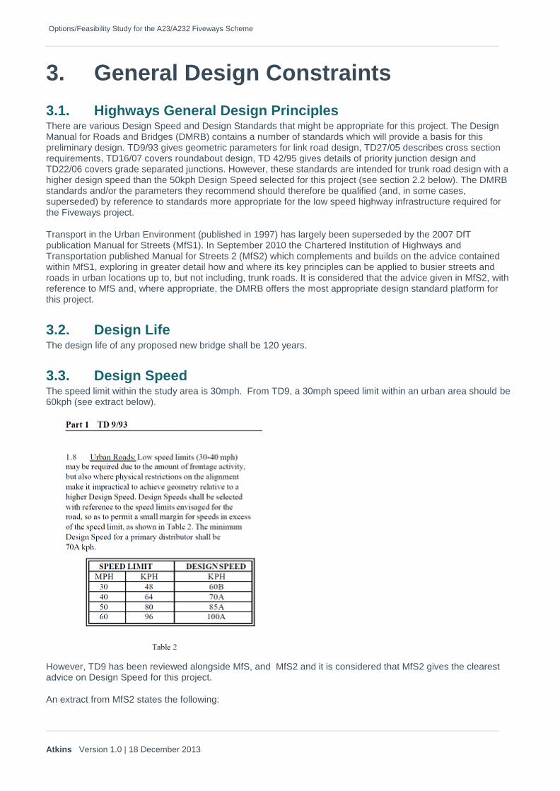
3.3. Design Speed The speed limit within the study area is 30mph. From TD9, a 30mph speed limit within an urban area should be 60kph (see extract below).
However, TD9 has been reviewed alongside MfS, and MfS2 and it is considered that MfS2 gives the clearest advice on Design Speed for this project.
An extract from MfS2 states the following:

Options/Feasibility Study for the A23/A232 Fiveways Scheme
Atkins Version 1.0 | 18 December 2013
The geometric design of carriageways is generally based on the notion of a design speed, which in the past has tended to be fixed along a route, or a substantial section of a route.
Design speeds in urban areas (or rural routes subject to a local speed limit) have tended to be based on the advice contained in DMRB TD 9/93, which determines design speed from the existing or proposed local speed limit, but with some allowance for vehicles travelling at higher speeds. In urban areas subject to a 30mph limit, a design speed of 60kph (37mph) has often been used.
It is now considered inappropriate in areas subject to a limit of 30mph, to adopt a design speed of more than 30 mph unless existing speeds are significantly above this level.
This is justified by the finding from the research contained in MfS1 that drivers tend to adopt higher speeds in response to more generous highway geometry and that, in recent years, the proportion of vehicles that exceed the speed limit in free flow conditions has been dropping; in 2008 it was below 50%, down from 69% in 1998. Average free flow speeds were 30mph in 30mph limits; and 36mph in 40mph limits.
A 30mph design speed is equivalent to 50kph. Therefore the Design Speed for the Fiveways project has been taken as 50kph as advised in MfS2.
3.4. Cross Section In accordance with TD 27/05, and taking into account TfL requirements, the bridge deck should have the following minimum cross-section:
Options 1 and 1a
Option 2
Table 3-1 Details of Proposed cross section

Options/Feasibility Study for the A23/A232 Fiveways Scheme
Atkins Version 1.0 | 18 December 2013
3.5. Horizontal Alignment MfS2 section 8.3 states:
The adoption of gentle minimum curve radii for new highways in urban areas can result in alignments that are inappropriate to the surrounding urban grain, sometimes requiring the acquisition and demolition of existing buildings and creating awkward plots of remaining land. This could be avoided if sharper curves were used The Sky Blue Way example in Chapter 2 shows the damage that can result when new highways are designed with generous curvature and widths.
Tighter radii can be adopted; TD9/93 para 3.4 advises that horizontal curves of four steps below desirable minimum radii can be used, "inter alia", for design speeds of 60kph and below. The relative sharpness of curves is established by the formula v2/R, where v=design speed (kph) and R= radius (m).
Horizontal curves of four steps below desirable minimum (TF9/93 para 0.7) have a v2/R value of 56, and therefore the minimum horizontal curves corresponding to this criterion are as follows:
Superelevation in urban areas should be kept to a minimum, since it is often difficult to achieve due to the frequency of accesses and junctions and other constraints. Excessive superelevation can also adversely affect the relationship between the carriageway and
frontage buildings and footways. When it is provided, a maximum superelevation in urban areas of 5% is recommended (TD9/93 para 3.2).
Where it is desirable to provide a horizontal curve below the values recommended in Table 8.1 above, the preferred solution will often be to reduce the speed of traffic locally, rather than provide steep superelevation, which will tend to encourage higher speeds.
The presence of a sharp bend will itself lead to lower speeds Research by TRL49 showed the following reductions in speed at bends (v = Approach Speed (kph),
R = Bend radius).
Options/Feasibility Study for the A23/A232 Fiveways Scheme
Atkins Version 1.0 | 18 December 2013
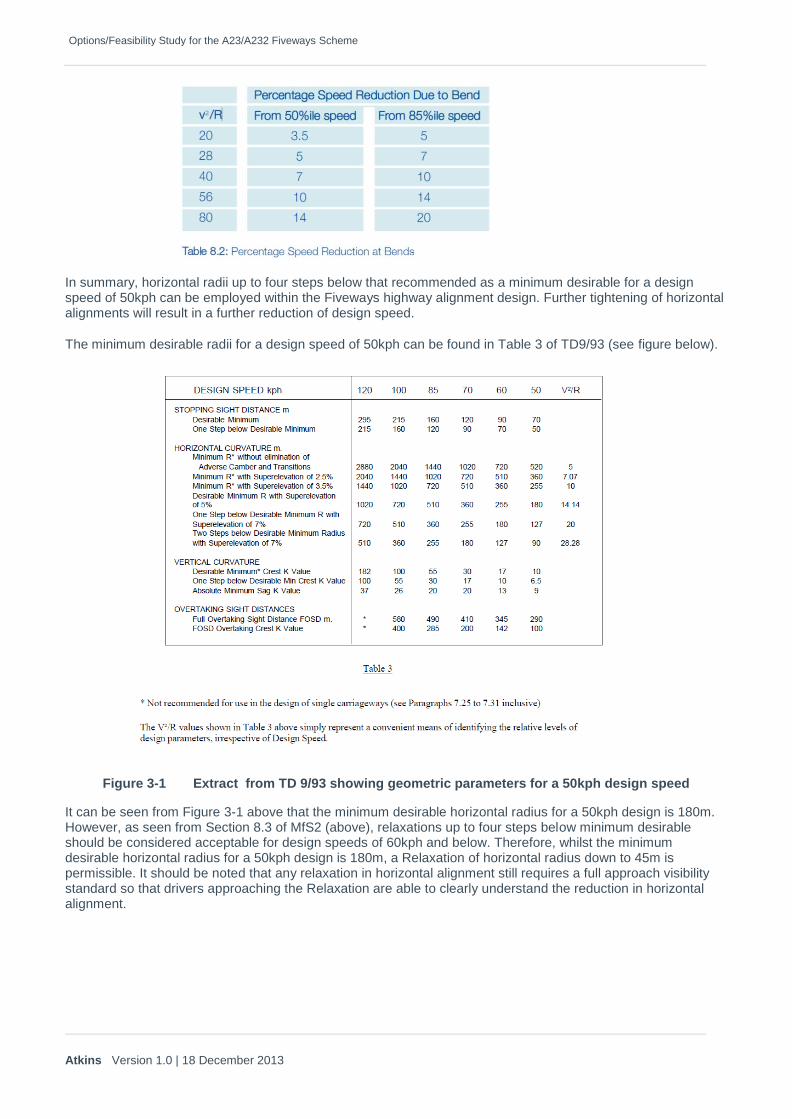
In summary, horizontal radii up to four steps below that recommended as a minimum desirable for a design speed of 50kph can be employed within the Fiveways highway alignment design. Further tightening of horizontal alignments will result in a further reduction of design speed.
The minimum desirable radii for a design speed of 50kph can be found in Table 3 of TD9/93 (see figure below).
Figure 3-1 Extract from TD 9/93 showing geometric parameters for a 50kph design speed
It can be seen from Figure 3-1 above that the minimum desirable horizontal radius for a 50kph design is 180m. However, as seen from Section 8.3 of MfS2 (above), relaxations up to four steps below minimum desirable should be considered acceptable for design speeds of 60kph and below. Therefore, whilst the minimum desirable horizontal radius for a 50kph design is 180m, a Relaxation of horizontal radius down to 45m is permissible. It should be noted that any relaxation in horizontal alignment still requires a full approach visibility standard so that drivers approaching the Relaxation are able to clearly understand the reduction in horizontal alignment.

Options/Feasibility Study for the A23/A232 Fiveways Scheme
Atkins Version 1.0 | 18 December 2013
3.6. Vertical Alignment Vertical curvature should accommodate the appropriate visibility requirements for the design speed of the road and also allow drivers to negotiate vertical curvature with some comfort. The minimum desirable k value for a crest curve is 10
Sag curves are determined by comfort and visibility, the latter defined by headlamp visibility. A minimum desirable 50kph sag curve has a k value of 11
The absolute minimum desirable k value for a sag curve at 50kph (comfort value) is 6.5.
Details of the vertical parameters appropriate for a 50kph link road can be seen in Table 3 of TD9/93 (see figure 2 above).
3.7. Visibility The Visibility requirements described in TD9/93 are calculated using the formula:
SSD = vt+v²/2(d+0.1a)
Where
SSD = Stopping Sight Distance; v= speed (m/s); t = driver perception time in seconds
d = deceleration (m/s²); a = longitudinal gradient.
For the SSD values in TD9/93, t is taken as 2 seconds, d is taken as 2.45 m/s² and ‘a’ is considered to be zero. However, MfS does not consider the above parameters to be appropriate in a low speed urban environment and states:
Drivers are normally able to stop much more quickly than this in response to an emergency. The stopping distances given in the Highway Code assume a driver reaction time of 0.67 seconds, and a deceleration rate of 6.57 m/s².
While it is not appropriate to design street geometry based on braking in an emergency, there is scope for using lower SSDs than those used in Design Bulletin 32. This is based upon the following:
• a review of practice in other countries has shown that Design Bulletin 32 values are much more conservative than those used elsewhere;
• research which shows that the 90th percentile reaction time for drivers confronted with a side-road hazard in a driving simulator is 0.9 seconds (see TRL Report 332);
• carriageway surfaces are normally able to develop a skidding resistance of at least 0.45g in wet weather conditions. Deceleration rates of 0.25g (the previously assumed value) are more typically associated with snow-covered roads; and
• of the sites studied in the preparation of this manual, no relationship was found between SSDs and casualties, regardless of whether the sites complied with Design Bulletin 32 or not.
For a low speed urban environment MfS recommends calculating SSD with a’ t’ value of 1.5 seconds and a ‘d’ value of 3.68 m/s² (for an HGV). These values, when substituted into the formula SSD = vt+v²/2(d+0.1a) gives the following SSD values for the following gradients:
Approach gradient SSD
-6% 53m
0% 47m
6% 44m
Table 3-2 Details of SSD for a 50kph urban design

Options/Feasibility Study for the A23/A232 Fiveways Scheme
Atkins Version 1.0 | 18 December 2013
3.8. Loading Any new bridge is proposed to be designed to BS EN 1992-2 as implemented by the UK National Annex. The new structure should be designed to carry SV 80, SV100 and SV 196 and any Special Order vehicle likely to be using the route.
3.9. Vertical Clearance
Options 1 and 1a Network Rail’s minimum acceptable headroom clearance requirement outlined in NR/L2/TRK/2049, for new construction on Primary InterCity main routes, is 4.780m. Although this route is not a Primary InterCity main route the headroom figure of 4.780m is assumed for this study as a conservative provision. This headroom will also accommodate OLE infrastructure/operations, but varies with route type. Network Rail has been requested to confirm the route type and the clearance requirements and future cant requirements. Any greater headroom will be difficult to achieve within the constraints of the site especially in terms of the longitudinal gradients required to merge with the existing roads on either ends of the elevated structure. For the purpose of this report, a minimum vertical clearance of 4.850m is assumed over, and between, the cess rails of the running lines for options 1 and 1a. This allows for total 70mm due to cant effect, construction tolerances and in-service bridge deck deflection under traffic live loading.
For the structure sections crossing the highway, a minimum headroom of 5.30m is used, in accordance with TD 27/05.
Option 2 Current vertical clearance is 4.270 to underside of the Waddon Station Bridge parapet tie beams.
Network Rail’s minimum acceptable headroom clearance requirement outlined in NR/L2/TRK/2049, for new construction on Primary InterCity main routes is 4.780m. Although this route is not a Primary InterCity main route the headroom figure of 4.780m is assumed for this study as a conservative provision the existing construction depth is shallow and poses a challenge to accommodate this clearance requirement. Network Rail has been requested to confirm the route type and the clearance requirements for this bridge.
For the purpose of this report, a minimum vertical clearance of 4.850m is assumed over, and between, the cess rails of the running lines. This includes allowance for the construction tolerances and in-service bridge deck deflection under the proposed traffic live loading.
It may be necessary to haunch the deck elements and as such the Network Rail minimum vertical clearances above the platform at various distances from its edge need to be in accordance to NR/L2/TRK/2049.
3.10. Railway Lateral Clearance
Options 1 and 1a The minimum lateral clearance for line speeds less than 100mph (as in this case) is 2.1m for a straight and level track from the running edges of the outside tracks to the nearest face of any obstruction. In order to provide a cess walkway of 700mm width it has been assumed that Network Rail will want 2.8m lateral clearance from cess rail running edges to the nearest face of any permanent element of the bridge. Bridge supports within 4.5m of the track need to be designed for train collision loads. In order to avoid the substantial project cost arising from bridge support elements located within the 4.5m clearance zone it is not proposed to place any bridge deck support within this zone for the purpose of developing various options.
3.11. Road Restraint Systems The parapets will be H4a containment class. This is a requirement of TfL, TAA and Network Rail for the sections over the rail corridor only (starting and finishing 3m beyond the location of any future OLE wiring). In the case of Waddon Bridge (Option 2) the substandard existing parapets and temporary vertical concrete barriers will need to be replaced.
Options/Feasibility Study for the A23/A232 Fiveways Scheme
Atkins Version 1.0 | 18 December 2013
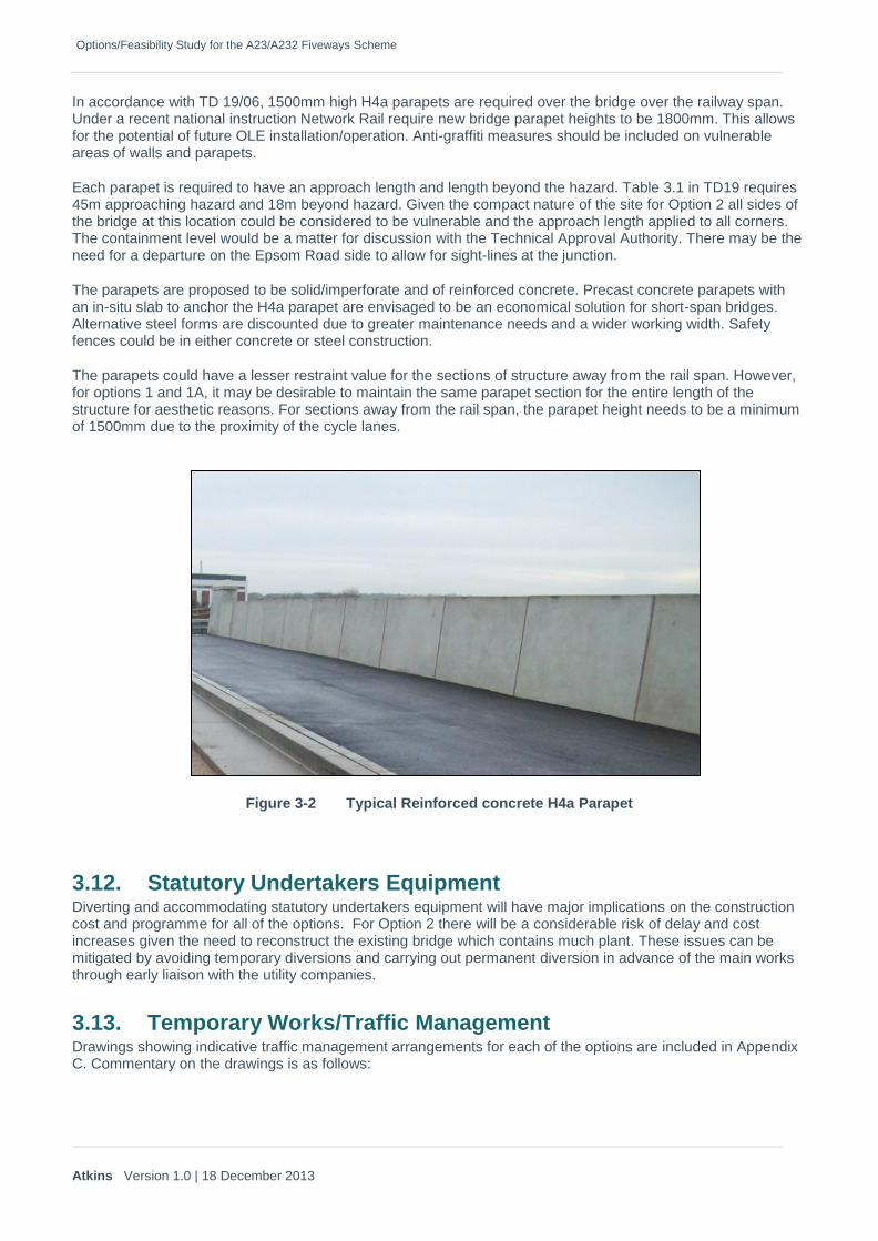
In accordance with TD 19/06, 1500mm high H4a parapets are required over the bridge over the railway span. Under a recent national instruction Network Rail require new bridge parapet heights to be 1800mm. This allows for the potential of future OLE installation/operation. Anti-graffiti measures should be included on vulnerable areas of walls and parapets.
Each parapet is required to have an approach length and length beyond the hazard. Table 3.1 in TD19 requires 45m approaching hazard and 18m beyond hazard. Given the compact nature of the site for Option 2 all sides of the bridge at this location could be considered to be vulnerable and the approach length applied to all corners. The containment level would be a matter for discussion with the Technical Approval Authority. There may be the need for a departure on the Epsom Road side to allow for sight-lines at the junction.
The parapets are proposed to be solid/imperforate and of reinforced concrete. Precast concrete parapets with an in-situ slab to anchor the H4a parapet are envisaged to be an economical solution for short-span bridges. Alternative steel forms are discounted due to greater maintenance needs and a wider working width. Safety fences could be in either concrete or steel construction.
The parapets could have a lesser restraint value for the sections of structure away from the rail span. However, for options 1 and 1A, it may be desirable to maintain the same parapet section for the entire length of the structure for aesthetic reasons. For sections away from the rail span, the parapet height needs to be a minimum of 1500mm due to the proximity of the cycle lanes.
Figure 3-2 Typical Reinforced concrete H4a Parapet
3.12. Statutory Undertakers Equipment Diverting and accommodating statutory undertakers equipment will have major implications on the construction cost and programme for all of the options. For Option 2 there will be a considerable risk of delay and cost increases given the need to reconstruct the existing bridge which contains much plant. These issues can be mitigated by avoiding temporary diversions and carrying out permanent diversion in advance of the main works through early liaison with the utility companies.
3.13. Temporary Works/Traffic Management Drawings showing indicative traffic management arrangements for each of the options are included in Appendix C. Commentary on the drawings is as follows:

Options/Feasibility Study for the A23/A232 Fiveways Scheme
Atkins Version 1.0 | 18 December 2013
Option 1: Phase 1 Offline works to be constructed first, to reduce any disruption to live traffic lanes. Access
locations to work areas may require some localised TM arrangement. This is to be discussed with the works contractor. No alteration to existing live carriageway operation. Offline works include westbound carriageway construction to Duppas Hill Road.
Phase 2 Westbound traffic from Duppas Hill Road transferred to new realigned southern slip road to enable commencement of construction to approach ramp and new bridge supports. Eastbound slip road preparation works commenced with eastbound traffic temporarily realigned to the southern side of the existing Duppas Hill Road. Access to residential properties directly accessed via Duppas Hill Road to be maintained through site.
Phase 3 Westbound traffic continues to run on new westbound slip road to enable continuing construction of bridge approach ramp and bridge supports. Eastbound slip road construction continues and eastbound traffic transferred back onto northern side of old Duppas Hill Road to enable commencement of eastbound level tie-in works with eastern end of new bridge approach/exit. Where central bridge piers are to be constructed to centre lanes of A23, southbound access from Epsom Road to Stafford Road is to be temporarily prevented to enable works access from beneath new bridge deck. The A23 operates within the TfL Lane Rental Scheme, and as such, works to construct the central piers is to be expedited where possible. Where access arrangements to this area may cause disruption to traffic flow, work is to be undertaken outside of peak hours. Traffic diverted from Epsom Road via Duppas Road and new westbound slip road. Completion of phase to include completion of Bridge deck and carriageway construction completion of new bridge and approach ends.
Phase 4 Traffic open to new bridge and approach road. New eastbound and westbound slip roads open. Access to Epsom Road southbound re-opened.
Option 1A: Phase 1 Offline works to be constructed first, to reduce any disruption to live traffic lanes. Access
locations to work areas may require some localised TM arrangement. This is to be discussed with the works contractor. No alteration to existing live carriageway operation. Offline works include westbound and eastbound carriageway construction to Duppas Hill Road.
Phase 2 Westbound traffic from Duppas Hill Road transferred to new realigned southern slip road to enable commencement of construction to approach ramp and new bridge supports. Eastbound traffic transferred onto newly constructed eastbound slip road, back onto ‘old’ Duppas Hill Road carriageway tie-in at eastern end of scheme. Access to residential properties directly accessed via Duppas Hill Road to be maintained through site.
Phase 3 Westbound traffic continues to run on new westbound slip road to enable continuing construction of bridge approach ramp and bridge supports. Eastbound traffic to continue to run on new eastbound slip road construction. Dedicated access road to residential properties to the north of Duppas Hill Road now open. Where central bridge piers are to be constructed to centre lanes of A23, southbound access from Epsom Road to Stafford Road is to be temporarily prevented to enable works access from beneath new bridge deck. The A23 operates within the TfL Lane Rental Scheme, and as such, works to construct the central piers is to be expedited where possible. Where access arrangements to this area may cause disruption to traffic flow, work is to be undertaken outside of peak hours. Traffic diverted from Epsom Road via Duppas Road and new westbound slip road. Completion of phase to include completion of Bridge deck and carriageway construction completion of new bridge and approach ends.
Phase 4 Traffic open to new bridge and approach road. New eastbound and westbound slip roads open. Access to Epsom Road southbound re-opened.
Option 2: Phase 1 Offline works to be constructed, including temporary bridge and supports. Supporting ground for
tie-in works to existing adjacent carriageway levels to be raised as near to existing levels where

Options/Feasibility Study for the A23/A232 Fiveways Scheme
Atkins Version 1.0 | 18 December 2013
possible. Offline works to include widening of Epsom Road to the south, and tie-in to existing western junction where possible. Services diverted and carried by the temporary bridge as required.
Phase 2 Westbound traffic on Epsom Road transferred onto newly constructed southern widened section to enable temporary bridge tie-in works to northern side of Epsom Road. Temporary bridge tie-in works to be completed where southbound traffic to be maintained and incorporated as part of level difference carriageway make-up. Final stages of phase to include transfer of southbound traffic by lanes onto temporary bridge deck followed by the transfer of the northbound traffic lanes. Two northbound and Southbound traffic lanes to be maintained, though alignment may be altered – reduced speed limits and ramp warning signs used to reduce vehicle speeds. Right turn traffic from Epsom Road to be accommodated as part of level tie-in works to southern end of bridge deck. Temporary traffic signals to be incorporated to traverse southbound lanes.
Phase 3 Northbound and southbound traffic transferred to temporary bridge, to enable demolition of old bridge deck with accompanying supports and construction of new bridge and supports. New works including offline carriageway level tie-in to be progressed as close to temporary bridge as possible. Traffic managed under temporary signals at Epsom Road and A23 junction.
Phase 4 Transfer of northbound traffic back onto new bridge deck, including level tie in works at either end of bridge deck ends (in reverse to Phase 2 works). Northbound traffic lanes to be maintained as two lanes and realigned to accommodate level difference make-up. Southbound traffic lanes to follow suit, post transfer of northbound lanes. Reduced speed limits and ramp warning signs used to reduce vehicle speeds. Right turn traffic from Epsom Road to be accommodated as part of level tie-in works to southern end of bridge deck. Temporary traffic signals to be incorporated to traverse southbound lanes. Epsom Road traffic to be pushed onto southern carriageway edge to allow for any surfacing and carriageway completion works to the northern footpath and railway station entrance (see note below regarding station access – localised realignment may be required to suit as required).
Phase 5 Northbound and southbound traffic running on new bridge deck. Westbound traffic from Epsom Road retained on the southern carriageway edge near to the A23 junction to complete removal of northern edge temporary bridge tie-in level make-up. Eastbound exit from Waddon Road station now open to traffic where full width of widened carriageway on Epsom Road will now be available to the east of the station entrance. Proposed signalisation re-working is expected at the junction of Epsom Road with Stafford Road. Temporary Bridge to be removed and any adjacent land reinstated as required.
Phase 6 Temporary bridge removed. Traffic running northbound and southbound on new bridge deck. Eastbound traffic now available on Epsom Road following completion of Phase 4 level tie-in works. Signal re-working is expected to the Epsom Road and A23 junction to allow eastbound travel on Epsom Road.
Access to Waddon Station to be maintained at all times.
The Traffic Management arrangements for each option are to consider the potential impacts to bus services and pedestrian movements. There are many bus routes serving the area with stops along Purley Way, Croydon Road, Stafford Road, Epsom Road and Duppas Hill Road. Where possible, any disruption to public transport services is to be minimized/ mitigated and discussed with public transport service providers. The existing pedestrian route use is to be investigated before the commencement of works and temporary pedestrian routes established as result.
It is proposed to retain the existing road space capacity wherever possible during the works activity phases. Both the A23 and A232 are roads designated on traffic sensitive routes where the TLRS applies. Where live traffic lanes are required to be relocated/switched with potential to cause disruption to the movement of traffic, this work is to be undertaken outside of peak hours.
Temporary traffic regulation orders may be required to maintain waiting restrictions on the traffic sensitive routes including the red routes.

Options/Feasibility Study for the A23/A232 Fiveways Scheme
Atkins Version 1.0 | 18 December 2013
3.14. Network Rail TfL intends to operate within an initial Network Rail Basic Service Agreement to provide for engineering consultation with regard to this scheme.
3.15. Other Stakeholders As this scheme is confidential, it was requested by TfL that there should be no stakeholder involvement in this study.
3.16. Architecture and Finishes The existing Waddon Bridge structure is generally not visible to the public since fencing and vegetation obscure views onto the railway. The only elements visible from the carriageway are the parapets and the TVCBs, neither of which have any aesthetic merit. However, the construction work for Option 2 may open up views and for
Therefore, any option pursued should be aesthetically pleasing and visually non-intrusive.
The final finish detail should be developed during any detailed design stage for the scheme.
Use of software such as VISSIM would be beneficial since it models individual vehicles through accurate representation of driving behaviour unlike more traditional software packages. VISSIM is an accepted means to assess traffic conditions and is used by TfL’s Road Space Management. The model should be developed in accordance with TfL’s Model Auditing process (VMAP).

Options/Feasibility Study for the A23/A232 Fiveways Scheme
Atkins Version 1.0 | 18 December 2013
4. Highways Design Option Development
4.1. Existing Topography
Options 1 and 1a
Option 2
Options/Feasibility Study for the A23/A232 Fiveways Scheme
Atkins Version 1.0 | 18 December 2013
4.2. Option 1 Parameters
4.2.1. Horizontal Alignment
4.2.2. Vertical Alignment
4.2.3. Visibility
4.2.4. Junctions
Options/Feasibility Study for the A23/A232 Fiveways Scheme
Atkins Version 1.0 | 18 December 2013
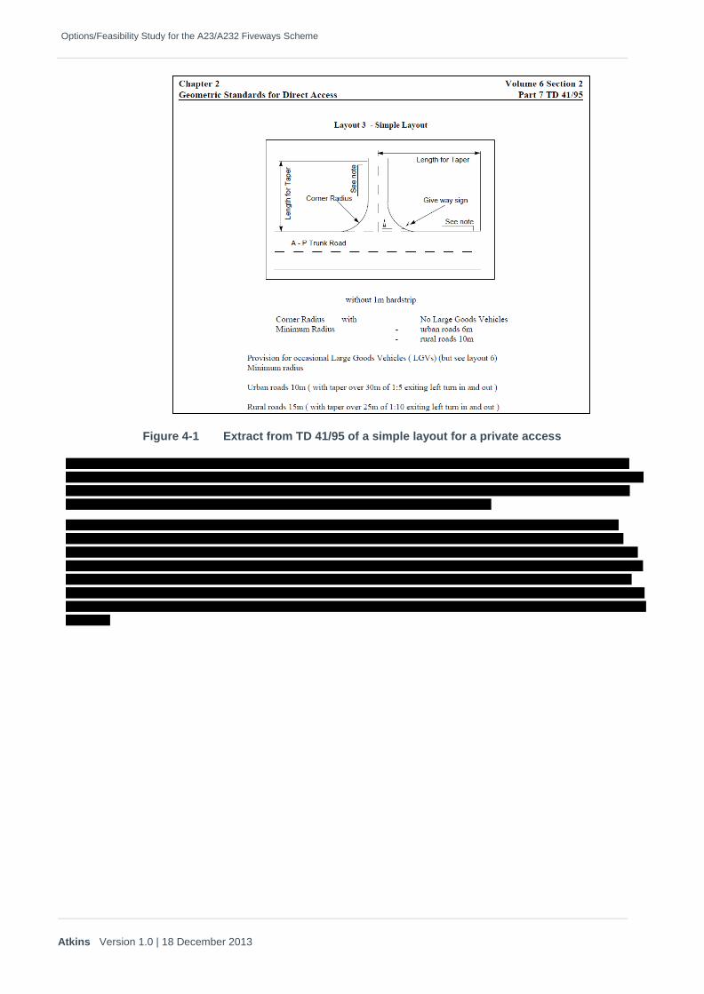
Figure 4-1 Extract from TD 41/95 of a simple layout for a private access

Options/Feasibility Study for the A23/A232 Fiveways Scheme
Atkins Version 1.0 | 18 December 2013
Figure 4-2 Diverge Slip Road layouts
Figure 4-3 Diverge Slip Road dimensions
4.2.5. NMU Provision

Options/Feasibility Study for the A23/A232 Fiveways Scheme
Atkins Version 1.0 | 18 December 2013
4.2.6. Cross-sectional detail
4.3. Option 1A Parameters
4.3.1. Horizontal Alignment
4.3.2. Vertical alignment
4.3.3. Visibility
4.3.4. Junctions

Options/Feasibility Study for the A23/A232 Fiveways Scheme
Atkins Version 1.0 | 18 December 2013
Figure 4-4 Merge Slip Road layouts
Figure 4-5 Merge Slip Road dimensions

Options/Feasibility Study for the A23/A232 Fiveways Scheme
Atkins Version 1.0 | 18 December 2013
The slip road has been designed to reflect the requirements of TD22’s Table 4 ‘Urban Road Speed Limit 50mph or less’ as described in figure 4-3.
4.3.5. NMU Provision
4.3.6. Cross-sectional detail
Figure 4-6 TD 27/05 Slip Road Cross Section Details

Options/Feasibility Study for the A23/A232 Fiveways Scheme
Atkins Version 1.0 | 18 December 2013
4.4. Option 2 Parameters
4.4.1. Horizontal Alignment
4.4.2. Vertical Alignment
4.4.3. Visibility
4.4.4. Junctions
4.4.5. Cross-sectional detail
Options/Feasibility Study for the A23/A232 Fiveways Scheme
Atkins Version 1.0 | 18 December 2013
5. Structural Design Option Development
Preliminary option development was undertaken to identify feasible solutions in terms of span arrangements and structural forms to suit the various options considered in this report.
Examination of the problem of replacing the A23 Waddon Station Bridge shows that there are many possibilities and sub options that would have to be developed in greater detail as the project progresses. The choice of solution depends on early decisions from the main stakeholders; TfL as road operators and Network Rail as track operators.
TfL: This report has been prepared on the basis of minimising traffic disruption on the A23. This requirement leads to the provision of a four lane temporary bridge to full design standards whilst reconstructing the existing. There would be no appreciable savings with the structure being temporary compared to permanent. If this combined with two sets of public utility diversions, onto a temporary and then to the permanent bridge it is likely that both the cost and programme will double.
If TfL consider that one weekend of road closure and diversion is acceptable then options that avoid any temporary bridge become viable. The programme and material savings would easily offset the cost of arranging the possession.
Network Rail: The new bridge can be built with abutments in front of the existing or behind the existing. Building in front of the existing abutment will require cooperation from Network Rail but would be less risky to a contractor and avoid having to make the substandard road alignment any worse. Building behind the abutment is a stage removed from Network Rail (although piling restrictions are likely to be the same) but adversely impacts on constructability and the final vertical alignment of the bridge.
In order to determine the viable options to be taken forward for further consideration it has been necessary to consider in more detail whether options would be acceptable to Network Rail and the constraints imposed by requirements for increased headroom with due consideration of the vertical highway alignment.
5.1. Structural Attributes
5.1.1. Deck Materials
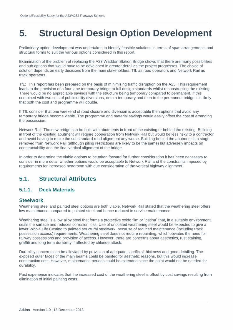
Steelwork Weathering steel and painted steel options are both viable. Network Rail stated that the weathering steel offers low maintenance compared to painted steel and hence reduced in service maintenance.
Weathering steel is a low alloy steel that forms a protective oxide film or “patina” that, in a suitable environment, seals the surface and reduces corrosion loss. Use of uncoated weathering steel would be expected to give a lower Whole Life Costing to painted structural steelwork, because of reduced maintenance (including track possession access) requirements. Weathering steel does not require repainting, which obviates the need for railway possessions and provision of access. However, there are concerns about aesthetics, rust staining, graffiti and long term durability if affected by chloride attack.
Durability concerns can be alleviated by provision of adequate sacrificial thickness and good detailing. The exposed outer faces of the main beams could be painted for aesthetic reasons, but this would increase construction cost. However, maintenance periods could be extended since the paint would not be needed for durability.
Past experience indicates that the increased cost of the weathering steel is offset by cost savings resulting from elimination of initial painting costs.

Options/Feasibility Study for the A23/A232 Fiveways Scheme
Atkins Version 1.0 | 18 December 2013
Weathering steel is perceived to be less aesthetically pleasing than painted steel. However, the use of weathering steel is becoming increasingly common in the UK and there has not been significant objection to its use by the public. The use at a station may well create concerns over perceived ambience as the bridge can be viewed close up. Rainwater run-off has to be controlled to prevent rust staining. Cleaning graffiti removes the patina and can therefore adversely affect the appearance. It will be difficult and costly to properly maintain a paint system over the railway.
Concrete Concrete would be used to form the deck slab.
The steel composite options would require a reinforced concrete deck slab approximately 250 mm thick and could utilise precast concrete participating or GRP non-participating permanent formwork to support the insitu concrete and any construction loads during construction. These permanent formwork systems are readily available and can be considered in the design of the deck slab accordingly.
GRP non-participating formwork is marginally more expensive than precast concrete participating formwork but it easier to install. It does not contribute towards the strength of the deck slab.
An alternative form of deck construction with precast concrete slabs acting compositely with steel beams in either ladder deck or multiple girder construction can be investigated further.
This form of construction offers advantages by simplifying the construction and reducing construction time providing significant benefits with the work required over the railway. Concrete parapets could be included in the precast deck units.
The disadvantages of this form of construction are developing details that can provide structural continuity in negative (hogging) moment areas and obtaining acceptance of the approving/maintaining authorities as they have in the past expressed concerns with the Serviceability Limit State design of the longitudinal joints between the concrete units and the need for tight tolerances during construction. Consultation with TFL and Network Rail regarding potential problems with acceptance would be required if this option is to be given further consideration.
Note: A paper published in the Institution of Civil Engineers Bridge Engineering journal No. 159 published in March 2006 describes a testing programme carried out to investigate joint performance and concludes that crack widths are unlikely to impose limitation at SLS.
GRP panelling used as permanent formwork for the deck is impermeable and where the ends and joints are sealed adequately, the ingress of harmful de-icing salts should be prevented.
Alternative forms of deck slab also considered were:
In situ concrete with traditional formwork supported either on the beams or from ground level. The formwork would need to be removed after the deck is cast. Therefore, it is not considered viable above a live railway due to the need for additional possessions.
Orthotropic steel decking – This option is more expensive and has health and safety issues due to the increased area of painting required both during construction and for maintenance.
5.1.2. Articulation BD 57/01 states that bridges with lengths not exceeding 60m and skews not exceeding 30 degrees shall be designed as integral bridges with abutments connected directly to the bridge deck without movement joints for expansion or contraction of the deck. The skew limit relates to the abutments rather than intermediate supports.
For Options 1 and 1A, the structure will have a total length in the region of 120m to 140m. The abutments will be square, but the intermediate supports will have a skew angle of approximately 55º. Owing to the length, an integral form of construction is not considered the most suitable solution and a conventional continuous steel-concrete composite ladder deck supported on bearings is proposed. However, the obvious benefits of a fully

Options/Feasibility Study for the A23/A232 Fiveways Scheme
Atkins Version 1.0 | 18 December 2013
integral option should not be dismissed, and, as such, consideration has also been made as to the feasibility of a fully integral solution. It is feasible for the bridge to be integral but the end details would need to be designed to avoid excessive forces in the deck that would arise from the restraint to its expansion caused by the large passive pressures mobilised in the soil behind the abutments if the deck is in contact with this soil. The detail at the end of the bridge would have to be capable of permitting approximately 30mm of movement in the pavement over the full temperature range. This has been achieved in Sweden and the US but details are not known and would require further research. Providing a properly designed expansion joint and inspection gallery would be the standard solution.
The general arrangement drawings for Options 1 and 1A include details for the fully integral variation on the structural solution. If either Option 1 or Option 1A is considered as being preferable to Option 2, evaluation of the two variations should be made to select a preferred bridge form.
For Option 2, the structure will have a maximum length of 30m with a skew of approximately 10º. Hence, a fully integral form of construction with multi-girder steel-concrete composite deck option is proposed. A saw cut joint would be provided behind each abutment to accommodate the small movements and control reflective cracking. Run-on slabs are not considered to be necessary.
5.1.3. Foundations The foundations of the existing Waddon Station Bridge are noted in the assessment report (WP Ref B435LBC) as at the interface between the Firm to Stiff Sandy Clay and medium Hard to Hard Chalk at 42m AOD, about 2m below Rail Level. It is likely that the existing bridge is founded ether in the Thanet Sands or Chalk. Some records indicate that under-pinning has been made. These records should be checked at the next stage of scheme development.
Shallow spread footings have been discounted at this stage as unlikely and reinforced concrete bored group piled foundations are considered for the purpose of this report. During design development, geotechnical risks should be fully appraised in accordance with HD 22/08. The geotechnical design and also potential contaminated land issues should be considered.
5.1.4. Details and Finishes Details and finishes for the concrete faces will be developed during any detailed design and agreed with TfL at the AIP stage.
5.1.5. Maintenance For concrete structures, salt spray and ingress of water through the deck can cause chloride attack, resulting in corrosion of reinforcement and spalling of the concrete. Environmental attack can cause carbonation of concrete, which may also result in corrosion of reinforcement. Steel structures require painting unless weathering steel is used.
All structures require inspection and maintenance but a properly detailed weathering steel-concrete composite deck would be the most cost effective solution in the long term. Weathering steel has disadvantages over appearance, rust staining and graffiti is difficult to remove affecting the surface patina so there may be aesthetic reasons why this would not be chosen. Network Rail is known not to favour painted structures as this requires track possessions to repaint.
Concrete structures can use of hydrophobic pore lining impregnants and the specification of concrete with a significant proportion of comment replacement to improve the durability of the concrete and minimise maintenance requirements. However, Highways Agency has temporarily suspended their use (Ref. CHE Memorandum 227/08) following research into their long term effectiveness and the use of similar products or alternative need to be discussed with the TfL during design stage.
Where bearings are used, they will be readily accessible from ground level with easy access for inspection and maintenance. The structure will incorporate facilities so that jacking for bearing replacement can be undertaken with minimal effect on the railway.
There will be no bearings on the structure for Option 2.
Options/Feasibility Study for the A23/A232 Fiveways Scheme
Atkins Version 1.0 | 18 December 2013
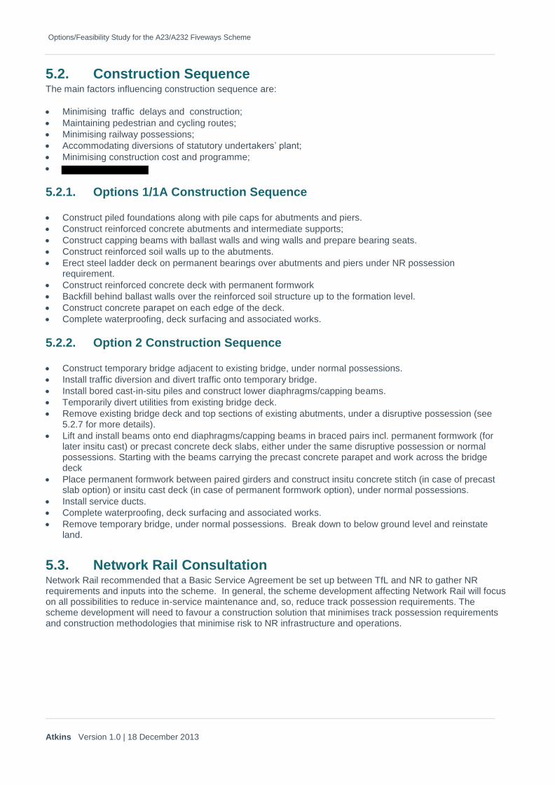
5.2. Construction Sequence The main factors influencing construction sequence are:
Minimising traffic delays and construction;
Maintaining pedestrian and cycling routes;
Minimising railway possessions;
Accommodating diversions of statutory undertakers’ plant;
Minimising construction cost and programme;
5.2.1. Options 1/1A Construction Sequence
Construct piled foundations along with pile caps for abutments and piers.
Construct reinforced concrete abutments and intermediate supports;
Construct capping beams with ballast walls and wing walls and prepare bearing seats.
Construct reinforced soil walls up to the abutments.
Erect steel ladder deck on permanent bearings over abutments and piers under NR possessionrequirement.
Construct reinforced concrete deck with permanent formwork
Backfill behind ballast walls over the reinforced soil structure up to the formation level.
Construct concrete parapet on each edge of the deck.
Complete waterproofing, deck surfacing and associated works.
5.2.2. Option 2 Construction Sequence
Construct temporary bridge adjacent to existing bridge, under normal possessions.
Install traffic diversion and divert traffic onto temporary bridge.
Install bored cast-in-situ piles and construct lower diaphragms/capping beams.
Temporarily divert utilities from existing bridge deck.
Remove existing bridge deck and top sections of existing abutments, under a disruptive possession (see5.2.7 for more details).
Lift and install beams onto end diaphragms/capping beams in braced pairs incl. permanent formwork (forlater insitu cast) or precast concrete deck slabs, either under the same disruptive possession or normalpossessions. Starting with the beams carrying the precast concrete parapet and work across the bridgedeck
Place permanent formwork between paired girders and construct insitu concrete stitch (in case of precastslab option) or insitu cast deck (in case of permanent formwork option), under normal possessions.
Install service ducts.
Complete waterproofing, deck surfacing and associated works.
Remove temporary bridge, under normal possessions. Break down to below ground level and reinstateland.
5.3. Network Rail Consultation Network Rail recommended that a Basic Service Agreement be set up between TfL and NR to gather NR requirements and inputs into the scheme. In general, the scheme development affecting Network Rail will focus on all possibilities to reduce in-service maintenance and, so, reduce track possession requirements. The scheme development will need to favour a construction solution that minimises track possession requirements and construction methodologies that minimise risk to NR infrastructure and operations.
Options/Feasibility Study for the A23/A232 Fiveways Scheme
Atkins Version 1.0 | 18 December 2013
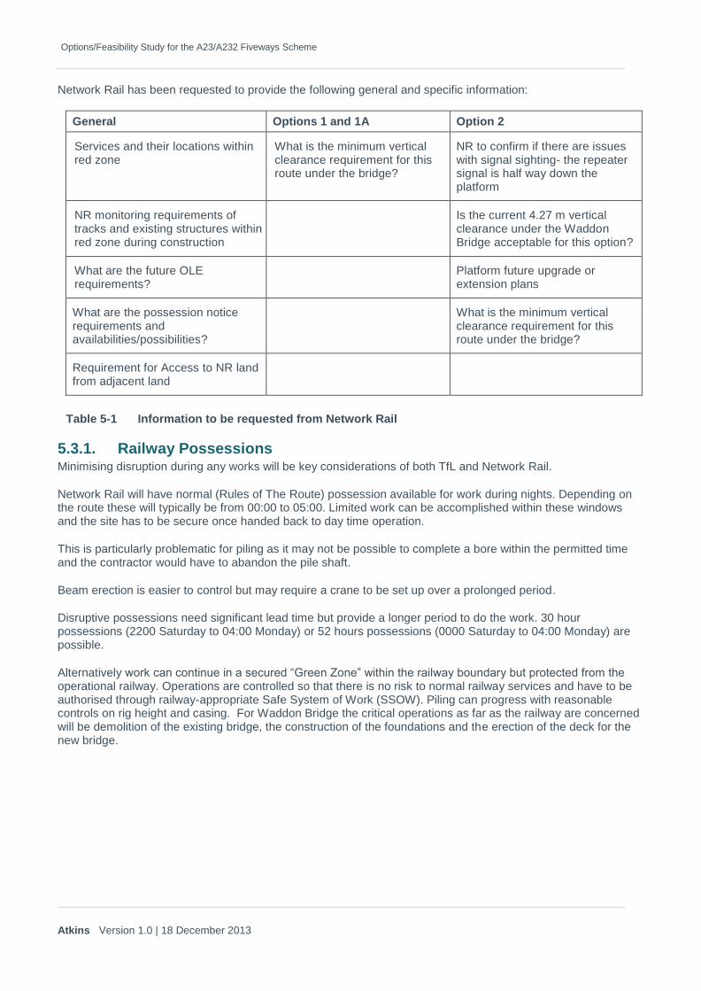
Network Rail has been requested to provide the following general and specific information:
General Options 1 and 1A Option 2
Services and their locations within red zone
What is the minimum vertical clearance requirement for this route under the bridge?
NR to confirm if there are issues with signal sighting- the repeater signal is half way down the platform
NR monitoring requirements of tracks and existing structures within red zone during construction
Is the current 4.27 m vertical clearance under the Waddon Bridge acceptable for this option?
What are the future OLE requirements?
Platform future upgrade or extension plans
What are the possession notice requirements and availabilities/possibilities?
What is the minimum vertical clearance requirement for this route under the bridge?
Requirement for Access to NR land from adjacent land
Table 5-1 Information to be requested from Network Rail
5.3.1. Railway Possessions Minimising disruption during any works will be key considerations of both TfL and Network Rail.
Network Rail will have normal (Rules of The Route) possession available for work during nights. Depending on the route these will typically be from 00:00 to 05:00. Limited work can be accomplished within these windows and the site has to be secure once handed back to day time operation.
This is particularly problematic for piling as it may not be possible to complete a bore within the permitted time and the contractor would have to abandon the pile shaft.
Beam erection is easier to control but may require a crane to be set up over a prolonged period.
Disruptive possessions need significant lead time but provide a longer period to do the work. 30 hour possessions (2200 Saturday to 04:00 Monday) or 52 hours possessions (0000 Saturday to 04:00 Monday) are possible.
Alternatively work can continue in a secured “Green Zone” within the railway boundary but protected from the operational railway. Operations are controlled so that there is no risk to normal railway services and have to be authorised through railway-appropriate Safe System of Work (SSOW). Piling can progress with reasonable controls on rig height and casing. For Waddon Bridge the critical operations as far as the railway are concerned will be demolition of the existing bridge, the construction of the foundations and the erection of the deck for the new bridge.
Options/Feasibility Study for the A23/A232 Fiveways Scheme
Atkins Version 1.0 | 18 December 2013
6. Appraisal of Options
One viable solution for each option has been taken forward for detailed appraisal.
6.1. Description of Viable Options
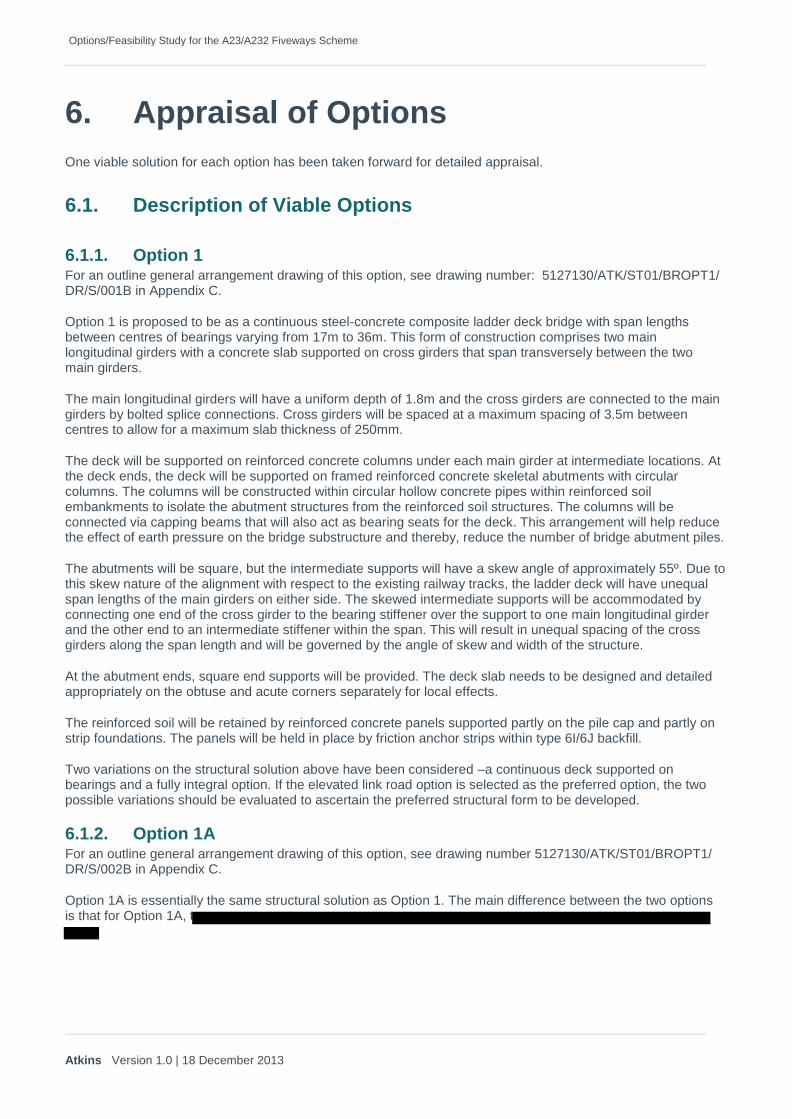
6.1.1. Option 1 For an outline general arrangement drawing of this option, see drawing number: 5127130/ATK/ST01/BROPT1/ DR/S/001B in Appendix C.
Option 1 is proposed to be as a continuous steel-concrete composite ladder deck bridge with span lengths between centres of bearings varying from 17m to 36m. This form of construction comprises two main longitudinal girders with a concrete slab supported on cross girders that span transversely between the two main girders.
The main longitudinal girders will have a uniform depth of 1.8m and the cross girders are connected to the main girders by bolted splice connections. Cross girders will be spaced at a maximum spacing of 3.5m between centres to allow for a maximum slab thickness of 250mm.
The deck will be supported on reinforced concrete columns under each main girder at intermediate locations. At the deck ends, the deck will be supported on framed reinforced concrete skeletal abutments with circular columns. The columns will be constructed within circular hollow concrete pipes within reinforced soil embankments to isolate the abutment structures from the reinforced soil structures. The columns will be connected via capping beams that will also act as bearing seats for the deck. This arrangement will help reduce the effect of earth pressure on the bridge substructure and thereby, reduce the number of bridge abutment piles.
The abutments will be square, but the intermediate supports will have a skew angle of approximately 55º. Due to this skew nature of the alignment with respect to the existing railway tracks, the ladder deck will have unequal span lengths of the main girders on either side. The skewed intermediate supports will be accommodated by connecting one end of the cross girder to the bearing stiffener over the support to one main longitudinal girder and the other end to an intermediate stiffener within the span. This will result in unequal spacing of the cross girders along the span length and will be governed by the angle of skew and width of the structure.
At the abutment ends, square end supports will be provided. The deck slab needs to be designed and detailed appropriately on the obtuse and acute corners separately for local effects.
The reinforced soil will be retained by reinforced concrete panels supported partly on the pile cap and partly on strip foundations. The panels will be held in place by friction anchor strips within type 6I/6J backfill.
Two variations on the structural solution above have been considered –a continuous deck supported on bearings and a fully integral option. If the elevated link road option is selected as the preferred option, the two possible variations should be evaluated to ascertain the preferred structural form to be developed.
6.1.2. Option 1A For an outline general arrangement drawing of this option, see drawing number 5127130/ATK/ST01/BROPT1/ DR/S/002B in Appendix C.
Option 1A is essentially the same structural solution as Option 1. The main difference between the two options is that for Option 1A, t
Options/Feasibility Study for the A23/A232 Fiveways Scheme
Atkins Version 1.0 | 18 December 2013
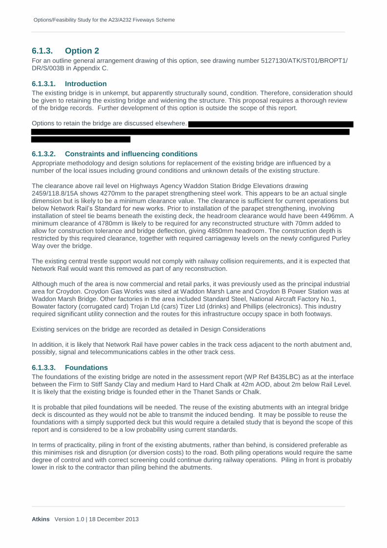
6.1.3. Option 2 For an outline general arrangement drawing of this option, see drawing number 5127130/ATK/ST01/BROPT1/ DR/S/003B in Appendix C.
6.1.3.1. Introduction
The existing bridge is in unkempt, but apparently structurally sound, condition. Therefore, consideration should be given to retaining the existing bridge and widening the structure. This proposal requires a thorough review of the bridge records. Further development of this option is outside the scope of this report.
Options to retain the bridge are discussed elsewhere.
6.1.3.2. Constraints and influencing conditions
Appropriate methodology and design solutions for replacement of the existing bridge are influenced by a number of the local issues including ground conditions and unknown details of the existing structure.
The clearance above rail level on Highways Agency Waddon Station Bridge Elevations drawing 2459/118.8/15A shows 4270mm to the parapet strengthening steel work. This appears to be an actual single dimension but is likely to be a minimum clearance value. The clearance is sufficient for current operations but below Network Rail’s Standard for new works. Prior to installation of the parapet strengthening, involving installation of steel tie beams beneath the existing deck, the headroom clearance would have been 4496mm. A minimum clearance of 4780mm is likely to be required for any reconstructed structure with 70mm added to allow for construction tolerance and bridge deflection, giving 4850mm headroom. The construction depth is restricted by this required clearance, together with required carriageway levels on the newly configured Purley Way over the bridge.
The existing central trestle support would not comply with railway collision requirements, and it is expected that Network Rail would want this removed as part of any reconstruction.
Although much of the area is now commercial and retail parks, it was previously used as the principal industrial area for Croydon. Croydon Gas Works was sited at Waddon Marsh Lane and Croydon B Power Station was at Waddon Marsh Bridge. Other factories in the area included Standard Steel, National Aircraft Factory No.1, Bowater factory (corrugated card) Trojan Ltd (cars) Tizer Ltd (drinks) and Phillips (electronics). This industry required significant utility connection and the routes for this infrastructure occupy space in both footways.
Existing services on the bridge are recorded as detailed in Design Considerations
In addition, it is likely that Network Rail have power cables in the track cess adjacent to the north abutment and, possibly, signal and telecommunications cables in the other track cess.
6.1.3.3. Foundations
The foundations of the existing bridge are noted in the assessment report (WP Ref B435LBC) as at the interface between the Firm to Stiff Sandy Clay and medium Hard to Hard Chalk at 42m AOD, about 2m below Rail Level. It is likely that the existing bridge is founded ether in the Thanet Sands or Chalk.
It is probable that piled foundations will be needed. The reuse of the existing abutments with an integral bridge deck is discounted as they would not be able to transmit the induced bending. It may be possible to reuse the foundations with a simply supported deck but this would require a detailed study that is beyond the scope of this report and is considered to be a low probability using current standards.
In terms of practicality, piling in front of the existing abutments, rather than behind, is considered preferable as this minimises risk and disruption (or diversion costs) to the road. Both piling operations would require the same degree of control and with correct screening could continue during railway operations. Piling in front is probably lower in risk to the contractor than piling behind the abutments.

Options/Feasibility Study for the A23/A232 Fiveways Scheme
Atkins Version 1.0 | 18 December 2013
Figure 6-1 Existing South Abutment and central trestle showing clearance to track
Figure 6-2 Existing North Abutment and adjacent platform
6.1.3.4. Span Arrangements and articulation
The new structure is proposed to be a single span bridge as it is likely that Network Rail will require the central trestle to be removed. The abutments are most likely to be constructed integrally with the bridge deck. This will provide a single span integral bridge.
The abutment width is estimated from unclear record drawings as 6’ thickening to 9’ at buttresses. Any piling would have to be clear of the wall so it is estimated that a 600mm clear gap would be required between the pile and the back of the existing abutment. Estimating 900mm pile diameter and 75mm positional tolerance would give an overall span of:

Options/Feasibility Study for the A23/A232 Fiveways Scheme
Atkins Version 1.0 | 18 December 2013
1.83m abutment
0.60m gap to piling
0.08m tolerance
0.45m pile diameter ______
2.96m x 2 = 5.92m
16.63m existing clear span (square) ______
22.55m span.
To consider a worst case scenario for the feasibility study we have allowed some extra tolerance of approximately two pile diameters either side to give an overall span of 26m.
This assumes that the piles can be installed without causing damage to the existing abutments.
The record drawings show sewers below the track running parallel with the road. Assuming these are still functioning then it will be harder to avoid the sewers when piling from road level compared to piling from track level. However, careful investigation to accurately locate the positions of the sewers should enable piling works to be carried out from road level without undue risk of damaging the sewers.
Alternative option would be to pipe jack a RC box underneath the road and then pile down from inside the jacked box. The box will form part of the permanent abutment. This will avoid all traffic disruption but is a very expensive option. Services should ideally be diverted before jacking the box in order to avoid damage through induced settlements.
The existing clear span is 16.63m (square). If the bridge were built in front of the existing abutments then the span would be reduced to about 13.5m.
A temporary bridge will be constructed on the East side of Waddon Bridge. The services also have to be removed before piling plant can cross the footways. Therefore the existing services will be diverted to the temporary bridge. Once the traffic is fully diverted onto the temporary bridge the permanent pile construction can be progressed.
An alternative option would require working in front of the abutments, which would require the agreement of Network Rail. Any Network Rail cables would have to be moved prior to works commencing. The site would then need to be secured by providing a full height fence/screen under the bridge and to the sides that were to be widened. The North side screen would be located behind the station platform to avoid disrupting passengers. Early consultation with Network Rail has revealed that whilst this option is potentially acceptable, it is not their preferred option. Retaining the cooperation of Network Rail would be important for the project.
With controls in place, it should be feasible to construct the widening section bridge piles either side of the existing bridge whilst permitting normal train operation. A stable, low headroom, rig could be used to satisfy NR about the risks to train operations.
Examples of piling techniques are shown below:

Options/Feasibility Study for the A23/A232 Fiveways Scheme
Atkins Version 1.0 | 18 December 2013
Figure 6-3 High Meads loop Construction
(used a 900mm piles installed by Martello piling rig adjacent to the railway, MP4000 rig)
Figure 6-4
River Worth Keighley Construction (Under a 3.1m headroom)

Options/Feasibility Study for the A23/A232 Fiveways Scheme
Atkins Version 1.0 | 18 December 2013
Figure 6-5 Wooferton Bridge Construction
Figure 6-6 Typical Piling Rig Layout

Options/Feasibility Study for the A23/A232 Fiveways Scheme
Atkins Version 1.0 | 18 December 2013
6.1.3.5. Structural Forms
The low construction depth available (800mm max, not including surfacing) will eliminate a number of deck form options.
The bridge deck could comprise of variable depth beams. The mid span section over the rails is limited to 800mm of construction depth, 550mm for steel girders and 250mm for a composite concrete deck. Near to the abutments the depth of the girders could increase in order to be more efficient and stiffen the abutment sections with a view to reducing live load moment at mid span.
Steel only solutions would not be cost effective for spans of this range and have significant whole life costs as noted above.
Alternatively, concrete could be used to form the deck either prestressed or reinforced concrete. To get to 26m span with low construction depth the prestressed beams would probably be Solid Box Beams [SD6(3) ref. Shay Murtgah catalogue]. Not regularly used, these beams are relatively heavy and can be packed with prestressing. They are typically used where headroom is an issue. The construction depth would be 925mm (construction depth is the structural dimension and excludes the surfacing. Surfacing varies to match the road cross section but has a minimum depth of 120mm). The beams can be made integral with the abutments through cast-in-situ reinforced concrete diaphragms
For shorter spans around 13.5m MY4 [ref. Shay Murtgah catalogue] could be used, which would comprise 450mm deep beams with a 150mm slab cast on top. Prestressed concrete offers advantages over perceived better long term durability, acceptable aesthetics and less area vulnerable to graffiti or bird roosting. U-beams or UM-beams can also be configured as service bays but are likely to be 300mm deeper for the same span.
Reinforced concrete decks 900mm deep could span up to 26m with some careful design. The recently completed integral Cowey Sale viaduct spans 27.9m with a 900mm deep construction depth. This was achieved with the made integral before release from the falsework. Although technically feasible with a jacking system the practicalities of integral construction and creep rule it out for further consideration at this stage when variable alternatives exist. Similarly post tensioned decks could span further, but practicality and durability concerns mean that it has not been considered further at this stage.
A decision over what is most cost effective depends upon contractor’s choice over method of construction, which will be a balance of price, programme and risk.
Figure 6-7 View of Existing Waddon Bridge from the station
(Telecommunications mast and control cabinet adjacent to the bridge. Network Rail cabinet located on far side of the bridge)

Options/Feasibility Study for the A23/A232 Fiveways Scheme
Atkins Version 1.0 | 18 December 2013
6.1.3.6. Records
Some records indicate that under-pinning has been made. These records should be checked at the next stage of scheme development.
6.1.3.7. Construction Sequence
Wing walls and approach retaining walls
The first step will be for the contractor to take possession of the site and commence site clearance. It is envisaged that the contractor would occupy the west side footpath up to the line of the existing temporary vertical concrete barriers. On the east side the telecommunications mast and equipment would need to be removed but the footpath would remain open to the public.
It is likely that vertical wing walls will retain the approach embankments. This is to avoid significant overspill onto the adjacent properties that an earthworks solution would create. The retaining walls will be parallel to the existing road, with the south-east retaining wall angled to accommodate the junction with Epsom Road.
To construct the retaining walls it is likely that a temporary sheet piled wall will be required alongside the existing road. This will permit the foundation construction. After this the retaining walls can be completed up to the finished level.
These operations can be executed without major disruption to rail or road traffic
6.1.3.8. Temporary Bridge for Diversion
The traffic needs to be diverted to the east of the existing structure prior to demolition and re-construction of the Waddon Bridge. In establishing the proposed construction sequence various issues and alternatives have been considered:
The temporary bridge deck will require H4a parapets. It is unlikely they could be readily accommodated on apropriety temporary bridging system;
It would require a large area of temporary land take;
There will be a need for additional railway possessions to dismantle the temporary bridge;
Traffic management during temporary bridge installation will be required.
Pedestrian access will need to be maintained along both sides of the temporary bridge.
The temporary bridge will be used to temporarily support statutory undertaker’s equipment, if necessary.
The temporary bridge will be approximately 20m long from face to face of the abutment walls. The temporary bridge will carry 4 lanes of traffic with footways on either side. The approximate maximum width of the deck will be 19m. This bridge will require a piled foundation as substructure to support the deck.
6.1.3.9. Demolition of Existing Bridge and Commencement of Installation of New Bridge Deck
Parapets With the west footpath occupied by the contractor, it will be straightforward to dismantle the steel parapet assembly during normal possessions. The east side will remain until the footway is diverted.
Services The services on each side of the existing bridge could be moved onto permanent service bridges to the west and east of the existing bridge. These will also carry the H4a parapets and form the edges of the new structure.
Beams and deck The existing bridge deck comprises compound steel girders with concrete jack arches spanning between girders and mass concrete fill supporting the road pavement.
Demolition will be done piecemeal or in one extended possession. In all cases, the existing track level infrastructure needs to be protected.

Options/Feasibility Study for the A23/A232 Fiveways Scheme
Atkins Version 1.0 | 18 December 2013
The disruptive possession would have the railway and road closed for 52 hours. Once possession has been achieved, the existing infrastructure would be protected including signals, lineside services, platform and rails. At road level, traffic signal loops would be disconnected beforehand. This operation is estimated to take 2 hours. (T+2).
The deck would be demolished using cranes and hydraulic concrete pulverisers or “munchers”.
The beam to central trestle fixings would need to be released first by cutting the fixing down bolts. Openings would be made in the deck to allow crane slings to be fixed under each beam. Lifting loops would be prepositioned before the general demolition commenced. This operation is expected to take 2 hours. (T+4).
Each beam would be under slung and supported by a crane to ensure stability. The concrete munchers would break through the jack arch crown along its centreline to free the outer beam, working from behind each abutment. Once the outer beam was separated cleared the crane would take the weight of the beam and remaining surrounding concrete and the munchers would complete the cut by separating any fixings of the beam at the supports. The beam would be lifted out and the next operation started until all beams were removed. With the deck removed the abutment can be locally reduced to remove any obstructions to the new construction. Small debris would fall onto the track level protection. No personnel are to go onto the bridge deck or below during demolition. This operation is expected to take 12 hours. (T+16).
The new abutment shelves would be uncovered once demolition was complete and new bridge beams would then be installed during the same possession. The crane used for demolition would now erect prefabricated deck sections.
The size of each section will depend on crane location, counter weight configuration and pick up position but heavy lifts of 300T are possible (M74 Completion Project lifted 300T steel girders with 60m reach but this required a very expensive crane). Assuming 100T as a starting point the crane could lift a 25m long deck panel, 2.5m wide. The deck would be assembled from five panels dropped in between the sections already completed outside the existing deck footprint. This operation is expected to take 10 hours. (T+26).
With the deck in place the trackside area can be cleared of any debris and the protection removed. This operation is expected to take 2 hours (T+28). Rail traffic could be restored at this point.
The deck panel assemblies would be landed on temporary bearings. Permanent GRP formwork would be used to bridge the gap between panels. Continuity reinforcement would be fixed and concrete cast to stitch the deck together. This operation would be done during normal railway operation over the following few weeks. The concrete stitch would need some time to gain strength before loading and then cure before application of water proofing. After the deck has been waterproofed the surfacing could be laid and road construction completed.
6.1.3.10. Reconstruction whilst using the A23 Waddon Station Bridge
There are a number of potential constraints that make it hard to construct a new bridge whilst maintaining the traffic flow. It is assumed that two lanes will be needed in each direction.
The widening is assumed to be start from the existing western kerbline as noted above (see highway design section).
The existing footpath area is assumed not be capable of carrying live load. The form is construction is different to the main part of the bridge. The beams comprise two service bays with the beams individually encased in concrete and steel cross girders carrying the services and any fill material. The distribution factors assumed in the assessment report would not apply to the service bays beams and wheel loads are not recorded as being assessed. It would be expected that the service bay would not support the applied load without some modification.
Any partial demolition would have to be done to suit the beam positions at 5’ (1.52m) centres. In order to leave a workable edge the carriageway would no closer than
330mm set back (minimum)
1800mm barrier THVCB working width (W6 if not recessed)

Options/Feasibility Study for the A23/A232 Fiveways Scheme
Atkins Version 1.0 | 18 December 2013
(1350mm maintenance access behind THVCB including edge protection)
300mm safety gap
2430mm
If the barrier is recessed by 200mm this could be reduced to
330mm set back (minimum)
800mm barrier THVCB working width (W2 recessed)
(600mm maintenance access behind THVCB including edge protection)
300mm safety gap
1680mm to the centreline of the remaining outer beam.
In simple terms this equates to two arch bays.
Similar clearances would be needed at the edge of any temporary road situation on new construction although recesses would be provided.
The resultant is that it would be practically difficult to get more than one lane on any partially demolished bridge. The other three would have to be carried on the construction outside the existing bridge along with a new footpath either a temporary bridge or part of the permanent bridge widening.
Given the additional risk and effort to ensure that the partially demolished bridge is maintained in a sound condition partial use of Waddon Bridge is not recommended.
6.1.3.11. Construction with closure of the A23.
If the A23 were closed for a period of 48 hours the bridge could be demolished and reconstructed over a single weekend. Traffic diversions and advance publicity would need to be implemented but the advantage would be in saving the cost and programme time for the temporary bridge construction.
The service bridges and widening could be completed either side of the existing bridge with normal railway possessions and all the services diverted once into a permanent location. The new bridge deck panels would be erected as noted above. Building in front of the existing abutments and using smaller beams would speed up time needed to complete the bridge.
Stitching the beams together and fixing deck reinforcement would follow on from beam erection but could be configured to not require further railway possessions. The deck and integral connection would then be cast and allowed to cure. The reinforcement would ideally be kept simple and prefabricated for speed. Eight hours is allowed for completing the deck. (T+36)
We have not investigated the necessary strengthen gain or early application of bridge deck waterproofing. We suggest that 12 hours is required for concrete strength gain and a temporary surface is used for traffic. The abutments would be backfilled at this point and carriageway reconstructed up to the bridge. (T+48)
To complete the construction, deck waterproofing would have to be laid. This could be done piecemeal using the increased width of the deck to allow night time traffic management for strips of temporary surfacing to be lifted deck waterproofed and permanent surfacing laid.
6.2. Estimated Initial Capital Costs
The estimated capital cost of each option is as follows:
Option 1
Option 1A
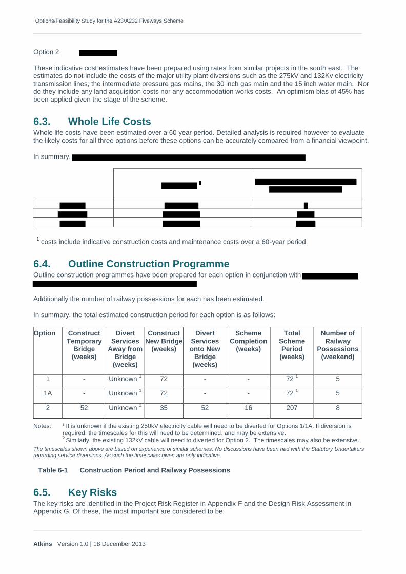
Options/Feasibility Study for the A23/A232 Fiveways Scheme
Atkins Version 1.0 | 18 December 2013
Option 2
These indicative cost estimates have been prepared using rates from similar projects in the south east. The estimates do not include the costs of the major utility plant diversions such as the 275kV and 132Kv electricity transmission lines, the intermediate pressure gas mains, the 30 inch gas main and the 15 inch water main. Nor do they include any land acquisition costs nor any accommodation works costs. An optimism bias of 45% has been applied given the stage of the scheme.
6.3. Whole Life Costs Whole life costs have been estimated over a 60 year period. Detailed analysis is required however to evaluate the likely costs for all three options before these options can be accurately compared from a financial viewpoint.
In summary,
1 costs include indicative construction costs and maintenance costs over a 60-year period
6.4. Outline Construction Programme Outline construction programmes have been prepared for each option in conjunction with
Additionally the number of railway possessions for each has been estimated.
In summary, the total estimated construction period for each option is as follows:
Option Construct Temporary
Bridge (weeks)
Divert Services
Away from Bridge (weeks)
Construct New Bridge
(weeks)
Divert Services onto New
Bridge (weeks)
Scheme Completion
(weeks)
Total Scheme Period (weeks)
Number of Railway
Possessions (weekend)
1 - Unknown 1
72 - - 72 1
5
1A - Unknown 1
72 - - 72 1
5
2 52 Unknown 2
35 52 16 207 8
Notes: 1 It is unknown if the existing 250kV electricity cable will need to be diverted for Options 1/1A. If diversion is required, the timescales for this will need to be determined, and may be extensive. 2
Similarly, the existing 132kV cable will need to diverted for Option 2. The timescales may also be extensive.
The timescales shown above are based on experience of similar schemes. No discussions have been had with the Statutory Undertakers regarding service diversions. As such the timescales given are only indicative.
Table 6-1 Construction Period and Railway Possessions
6.5. Key Risks The key risks are identified in the Project Risk Register in Appendix F and the Design Risk Assessment in Appendix G. Of these, the most important are considered to be:

Options/Feasibility Study for the A23/A232 Fiveways Scheme
Atkins Version 1.0 | 18 December 2013
Gaining agreement from Network Rail for:
Headroom,
Lateral clearance,
Use of Network Rail land,
Possessions;
Diversion of statutory undertakers equipment;
Demolition method for the existing structure;
Maintaining the integrity of the existing structure whilst partly demolished.
6.6. Departures from Standard
For this feasibility design, departures from standard will be needed to provide the highway alignment within the geographical constraints as follows:
Option 1
Option 1A
No departures identified
Option 2
Also, the vertical curvature departure will create a forward visibility departure to the low object heightalthough traffic speeds will be low here.
There will be numerous other departures required for length of road restraint system etc necessitated by the urban layout. These are not unusual in such confined locations; the low traffic speeds can be viewed as mitigation. These additional departures will need to be identified during subsequent design stages.
6.7. Advantages and Disadvantages
6.7.1. Option 1
6.7.1.1. Advantages
1. Option 1 provides a clear link for the A232 from Duppas Hill Road to Croydon Road. Traffic wishingto continue eastbound or westbound along the A232 will not need to access the Fiveways junction.Similarly, traffic on the A232 westbound, wishing to travel north on the A23 will also not need toaccess the Fiveways junction. Although no traffic data has been made available, and it was statedthat traffic analysis should not be carried out as part of this feasibility study, the elevated link roadshould clearly reduce pressure on the Fiveways junction together with the other road junctions in thevicinity.
2. Option 1 meets the required clearances over both road and rail, and the longfalls on the elevated linkroad can also achieve design standards.
3.

Options/Feasibility Study for the A23/A232 Fiveways Scheme
Atkins Version 1.0 | 18 December 2013
6.7.1.2. Disadvantages
1.
2.
3.
4. Any maintenance work required on the A23 Waddon Station Bridge would still be needed. The temporary vertical concrete barriers would not be replaced. This would leave a visual impact and possibly have a procedural impact if Network Rail requires the existing parapet be addressed as part of supporting the new bridge project.
6.7.2. Option 1A
6.7.2.1. Advantages
1. Option 1A provides a clear link for the A232 from Duppas Hill Road to Croydon Road. Traffic wishing to continue eastbound or westbound along the A232 will not need to access the Fiveways junction. Similarly, traffic on the A232 westbound, wishing to travel north on the A23 will also not need to access the Fiveways junction. Although no traffic data has been made available, and it was stated that traffic analysis should not be carried out as part of this feasibility study, the elevated link road should clearly reduce pressure on the Fiveways junction together with the other road junctions in the vicinity.
2. Option 1 meets the required clearances over both road and rail, and the longfalls on the elevated link road can also achieve design standards.
3.
4. The majority of option 1 can be constructed ‘off line’, which will reduce the additional delays likely to be caused during the construction phase.
5. The main advantage of Option 1A over Option 1 is that the elevated link road
6.7.2.2. Disadvantages
1.

Options/Feasibility Study for the A23/A232 Fiveways Scheme
Atkins Version 1.0 | 18 December 2013
2.
3.
6.7.3. Option 2
6.7.3.1. Advantages
1.
2.
3.
4. The project upgrades an existing bridge asset so that the future maintenance cost will be low.
5. The environmental impact of a new bridge would be less than the Option 1 and not dissimilar to theexisting bridge (small changes of width and vertical profile).
6.7.3.2. Disadvantages
1. Option 2 will require removal of the existing bridge and construction of a new wider bridge in itsplace. Traffic access will need to be maintained across the railway, and hence a temporary bridgewill need to be constructed adjacent to the current bridge, assuming that a closure of the A23 is notpermitted. This will require construction adjacent to and over Network Rail property/infrastructure,and will require a number of rail possessions. This imposes additional risks on the constructionprogramme.
2. Although the temporary bridge will maintain four lanes of traffic over the railway, the lanes will haveto be reduced to minimum allowed width, and speed restrictions will have to be imposed throughoutthe construction period. This will inevitably add to increased traffic delays throughout the project.
3. No traffic data has been made available, and it was stated that traffic analysis should not be carriedout as part of this feasibility study.
A detailed traffic management exercise would help quantify the benefits ofeach option in terms of impact on vehicle numbers at each junction in the area.
4.

Options/Feasibility Study for the A23/A232 Fiveways Scheme
Atkins Version 1.0 | 18 December 2013

Options/Feasibility Study for the A23/A232 Fiveways Scheme
Atkins Version 1.0 | 18 December 2013
7. Health and Safety Considerations
The Design Risk Assessment is included in Appendix G.
No additional health and safety issues are envisaged apart from those normally related to construction in similar site conditions adjacent to an electrified railway and a busy road. The key health and safety issues are:
Working in a railway environment;
Working in a highway environment on a high speed, high capacity route;
Working at height;
Maintaining edge protection during construction sufficient to protect the railway below;
Night time working;
Working near utilities plant, including high voltage electricity cables and an intermediate pressure gas main;
Operation of heavy machinery including cranes and piling plant;
Demolition including maintaining stability of the partly demolished bridge;
Hazards to the public and road users (motorists, cyclists and pedestrians);
Hand arm vibration injury;
Manual lifting;
Noise.
For Option 2, the scheme will provide improved vehicle restraint systems that will enhance the safety of the travelling public by better containment of errant vehicles.
The increased lateral and headroom clearance and the removal of the bridge piers will improve the safety of the operation of the railway.

Options/Feasibility Study for the A23/A232 Fiveways Scheme
Atkins Version 1.0 | 18 December 2013
8. Environmental Considerations
8.1. Potential Ecological Constraints
An outline of the potential constraints identified has been prepared for the two options. This is an approximate outline of potential ecological issues and it is recommend that a site visit and site survey are carried out to ensure the constraints identified are dealt with appropriately.
Protected species records and non-statutory sites searches have not been requested from the local environmental records centre given the confidentiality of the study. In the absence of a detailed study, no comments have been provided with regard to invasive plants.
An internet search1 has revealed information on non-statutory designated sites, but while this has been used to
provide approximate distances between the option locations and the designated sites, it has not provided site descriptions and the current status of the sites cannot be confirmed without a formal study data search.
The search for water bodies within 500 m of the site was undertaken using Ordnance Survey plans and aerial photographs only. These sources may not show all ponds and or water bodies within 500 m of the site boundary and therefore some water bodies may not have been identified.
A copy of the Atkins Ecology Calendar has been provided in Appendix H which highlights the potential timings of ecology work which need to be considered in advance of scheme construction.
1 http://www.croydon.gov.uk/contents/departments/planningandregeneration/pdf/evidence/snci-review.pdf

Options/Feasibility Study for the A23/A232 Fiveways Scheme
Atkins Version 1.0 | 18 December 2013
Option 1
Non-statutory designated sites within 2km that were identified from an internet source are listed in the following table:
Site Name and designation
Distance and direction from site
OS Grid Reference
Reason for proposed designation
Duppas Hill (CrBI21)
Local SINC TQ 31615 64841
No data available from initial search.
Waddon Ponds
(CrL03)
Local SINC
TQ 30952 65086
Wandle Park (CrL02)
Local SINC
TQ 31541 65626
Park Hill (CrL08)
Local SINC
TQ 32907 65059
Whitgift School Wood (CrBII09)
Borough Grade II SINC
TQ 32157 63886
Haling Grove Park (CrL04)
Local SINC
TQ 32092 63162
Addiscombe Railway Park & Selsdon &
Addiscombe railsides (CrBII26)
Borough Grade II SINC
TQ 33075 64121
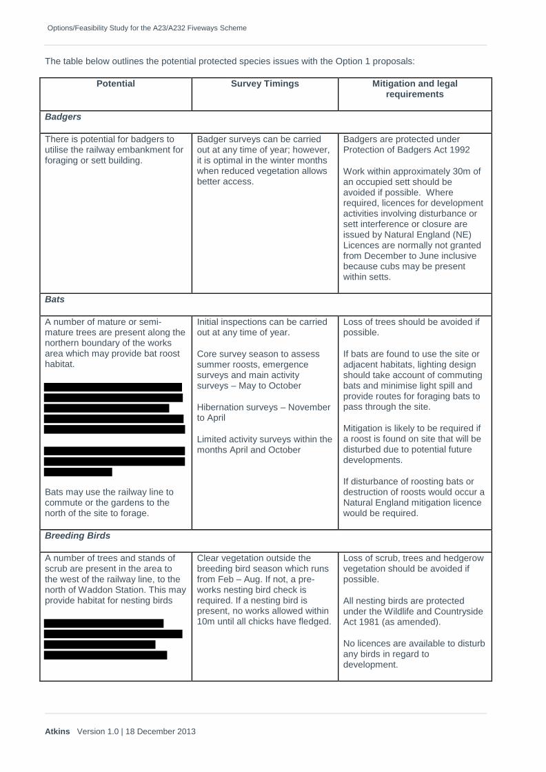
Options/Feasibility Study for the A23/A232 Fiveways Scheme
Atkins Version 1.0 | 18 December 2013
The table below outlines the potential protected species issues with the Option 1 proposals:
Potential Survey Timings Mitigation and legal requirements
Badgers
There is potential for badgers to utilise the railway embankment for foraging or sett building.
Badger surveys can be carried out at any time of year; however, it is optimal in the winter months when reduced vegetation allows better access.
Badgers are protected under Protection of Badgers Act 1992
Work within approximately 30m of an occupied sett should be avoided if possible. Where required, licences for development activities involving disturbance or sett interference or closure are issued by Natural England (NE) Licences are normally not granted from December to June inclusive because cubs may be present within setts.
Bats
A number of mature or semi-mature trees are present along the northern boundary of the works area which may provide bat roost habitat.
Bats may use the railway line to commute or the gardens to the north of the site to forage.
Initial inspections can be carried out at any time of year.
Core survey season to assess summer roosts, emergence surveys and main activity surveys – May to October
Hibernation surveys – November to April
Limited activity surveys within the months April and October
Loss of trees should be avoided if possible.
If bats are found to use the site or adjacent habitats, lighting design should take account of commuting bats and minimise light spill and provide routes for foraging bats to pass through the site.
Mitigation is likely to be required if a roost is found on site that will be disturbed due to potential future developments.
If disturbance of roosting bats or destruction of roosts would occur a Natural England mitigation licence would be required.
Breeding Birds
A number of trees and stands of scrub are present in the area to the west of the railway line, to the north of Waddon Station. This may provide habitat for nesting birds
Clear vegetation outside the breeding bird season which runs from Feb – Aug. If not, a pre-works nesting bird check is required. If a nesting bird is present, no works allowed within 10m until all chicks have fledged.
Loss of scrub, trees and hedgerow vegetation should be avoided if possible.
All nesting birds are protected under the Wildlife and Countryside Act 1981 (as amended).
No licences are available to disturb any birds in regard to development.
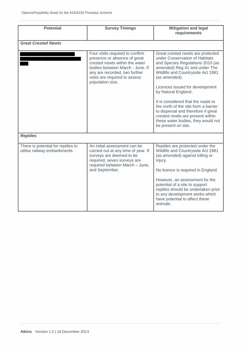
Options/Feasibility Study for the A23/A232 Fiveways Scheme
Atkins Version 1.0 | 18 December 2013
Potential Survey Timings Mitigation and legal requirements
Great Crested Newts
.
Four visits required to confirm presence or absence of great crested newts within the water bodies between March - June. If any are recorded, two further visits are required to assess population size.
Great crested newts are protected under Conservation of Habitats and Species Regulations 2010 (as amended) Reg 41 and under The Wildlife and Countryside Act 1981 (as amended).
Licences issued for development by Natural England.
It is considered that the roads to the north of the site form a barrier to dispersal and therefore if great crested newts are present within these water bodies, they would not be present on site.
Reptiles
There is potential for reptiles to utilise railway embankments.
An initial assessment can be carried out at any time of year. If surveys are deemed to be required, seven surveys are required between March – June, and September.
Reptiles are protected under the Wildlife and Countryside Act 1981 (as amended) against killing or injury.
No licence is required in England.
However, an assessment for the potential of a site to support reptiles should be undertaken prior to any development works which have potential to affect these animals.

Options/Feasibility Study for the A23/A232 Fiveways Scheme
Atkins Version 1.0 | 18 December 2013
Option 2
Non-statutory designated sites within 2km that were identified from an internet source are listed in the following table:
Site Name and designation
Distance and direction from site
OS Grid Reference
Reason for proposed designation
Duppas Hill (CrBI21)
Local SINC TQ 31615 64841
No data available from initial search.
Waddon Ponds
(CrL03)
Local SINC
TQ 30952 65086
Wandle Park (CrL02)
Local SINC
TQ 31541 65626
Park Hill (CrL08)
Local SINC
TQ 32907 65059
Whitgift School Wood (CrBII09)
Borough Grade II SINC
TQ 32157 63886
Haling Grove Park (CrL04)
Local SINC
TQ 32092 63162
Addiscombe Railway Park & Selsdon &
Addiscombe railsides (CrBII26)
Borough Grade II SINC
TQ 33075 64121

Options/Feasibility Study for the A23/A232 Fiveways Scheme
Atkins Version 1.0 | 18 December 2013
The table below outlines the potential protected species issues with the Option 2 proposals:
Potential Survey Timings Mitigation and legal requirements
Badgers
There is potential for badgers to utilise the railway embankment for foraging or sett building.
Badger surveys can be carried out at any time of year; however, it is optimal in the winter months when reduced vegetation allows better access.
Badgers are protected under Protection of Badgers Act 1992
Work within approximately 30m of an occupied sett should be avoided if possible. Where required, licences for development activities involving disturbance or sett interference or closure are issued by Natural England (NE) Licences are normally not granted from December to June inclusive because cubs may be present within setts.
Bats
A number of mature or semi-mature trees are present
which may provide bat roost habitat.
The A23 Purley Way bridge may provide bat roost habitat.
Bats may use the railway line to commute or the gardens to the north of the site to forage.
Initial inspections can be carried out at any time of year.
Core survey season to assess summer roosts, emergence surveys and main activity surveys – May to October
Hibernation surveys – November to April
Limited activity surveys within the months April and October
Loss of trees should be avoided if possible.
If bats are found to use the site or adjacent habitats, lighting design should take account of commuting bats and minimise light spill and provide routes for foraging bats to pass through the site.
Mitigation is likely to be required if a roost is found on site that will be disturbed due to potential future developments.
If disturbance of roosting bats or destruction of roosts would occur a Natural England mitigation licence would be required.
Breeding Birds
There is a small stand of scrub
which provides potential breeding bird habitat.
A hedgerow and a number of mature or semi-mature trees are
Clear vegetation outside the breeding bird season which runs from Feb – Aug. If not, a pre-works nesting bird check is required. If a nesting bird is present, no works allowed within 10m until all chicks have fledged.
Loss of scrub, trees and hedgerow vegetation should be avoided if possible.
All nesting birds are protected under the Wildlife and Countryside Act 1981 (as amended).
No licences are available to disturb
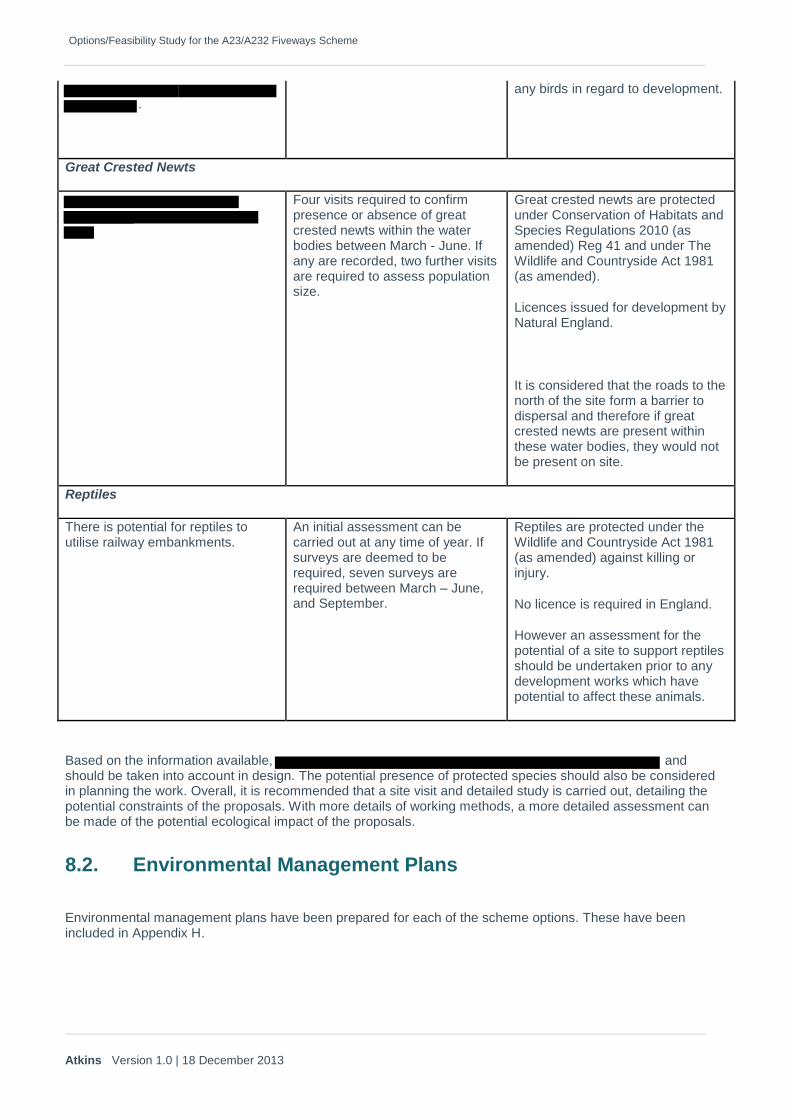
Options/Feasibility Study for the A23/A232 Fiveways Scheme
Atkins Version 1.0 | 18 December 2013
.
any birds in regard to development.
Great Crested Newts
Four visits required to confirm presence or absence of great crested newts within the water bodies between March - June. If any are recorded, two further visits are required to assess population size.
Great crested newts are protected under Conservation of Habitats and Species Regulations 2010 (as amended) Reg 41 and under The Wildlife and Countryside Act 1981 (as amended).
Licences issued for development by Natural England.
It is considered that the roads to the north of the site form a barrier to dispersal and therefore if great crested newts are present within these water bodies, they would not be present on site.
Reptiles
There is potential for reptiles to utilise railway embankments.
An initial assessment can be carried out at any time of year. If surveys are deemed to be required, seven surveys are required between March – June, and September.
Reptiles are protected under the Wildlife and Countryside Act 1981 (as amended) against killing or injury.
No licence is required in England.
However an assessment for the potential of a site to support reptiles should be undertaken prior to any development works which have potential to affect these animals.
Based on the information available, and should be taken into account in design. The potential presence of protected species should also be considered in planning the work. Overall, it is recommended that a site visit and detailed study is carried out, detailing the potential constraints of the proposals. With more details of working methods, a more detailed assessment can be made of the potential ecological impact of the proposals.
8.2. Environmental Management Plans
Environmental management plans have been prepared for each of the scheme options. These have been included in Appendix H.

Options/Feasibility Study for the A23/A232 Fiveways Scheme
Atkins Version 1.0 | 18 December 2013
9. Conclusions
It is recommended that Option 1 and Option 1A are to be investigated further. Option 1 and 1A are relatively similar and the only difference being Option 1 and 1A will also require fewer Network Rail possession for construction compared to Option 2.
However, Option 2 should not be dismissed whilst consultations with the local authority and public are ongoing. This will support a strong negotiation stance for Option 1 and 1A that can improve the whole corridor by opening up new connectivity. Option 2 could have a sub-option in the form of retaining the existing structure and widening on one side to accommodate additional lanes.
10. Recommendations
Solutions for the three options to be considered have been reviewed in this report, and preferred forms for each solution have been selected and studied in a little detail.
The cost of each option, both in terms of construction cost and whole life costs and the benefit of each option in terms of improvement to traffic flow is are significant factors. Other factors include aesthetics, disruption during construction and impact on local residents and businesses.
Preliminary estimates for the constructions costs of each option have been carried out, together with very basic whole life costing. Volume 1 of the invitation to tender indicated that cost estimates for the options were to be provided by a separate consultant. At subsequent progress meetings, TfL advised that this would not now be available for use in the report process and that costs for the options would not be able to be evaluated at feasibility stage. It is recommended that detailed cost estimates should be undertaken.
Traffic flow is probably the main factor in selecting the preferred option. No existing traffic data was made available as part of this feasibility study, and it was stated that no traffic modelling should be undertaken. It is not possible therefore to make a quantitative evaluation as the benefits of each option in terms of reduction in traffic flow at each of the junctions in the area are unknown. It is recommended that traffic surveys are undertaken to measure existing traffic flows, and that subsequent traffic modelling is undertaken to analyse the benefits of the three options.
For this feasibility study, the scheme design has been based on a combination of Ordnance Survey data and a LIDAR survey of the area. Neither of these methods provides information of sufficient accuracy to allow detailed design to be reliably undertaken. It is therefore recommended that a detailed topographical survey of the area is carried out in advance of the next phase of the scheme.
It is noted that there are very high voltage electricity transmission lines in the vicinity of the proposed elevated link road and along Purley Way. It has not been possible to obtain estimates of any diversionary work that may be necessary on this plant. It is therefore recommended that discussions are commenced with statutory undertakers with major elements of plant which may require diversion/protection at the earliest possible opportunity as the results of these discussions may have a significant influence of the choice of preferred option.
An environmental desk study has identified that there are several areas which could be inhabited by protected species. It is recommended that environmental and ecological walkover survey are undertaken at appropriate times of the year to determine whether these species are present so that suitable mitigation can be developed early in the project design stages.
A meeting has been held with Network Rail as part of this feasibility study, and potential rail possessions were discussed. It is recommended that these discussions be continued during the selection of a preferred option, to give a more robust likelihood of a construction programme.

Atkins Version 1.0 | 18 December 2013
Appendices
Options/Feasibility Study for the A23/A232 Fiveways Scheme
Atkins Version 1.0 | 18 December 2013 60
Appendix A. Existing Bridge Record Information

Options/Feasibility Study for the A23/A232 Fiveways Scheme
Atkins Version 1.0 | 18 December 2013 61
Appendix B. Existing Statutory Undertaker’s Information

Options/Feasibility Study for the A23/A232 Fiveways Scheme
Atkins Version 1.0 | 18 December 2013 62
Appendix C. Drawings
INFORMATION WITHELD

Options/Feasibility Study for the A23/A232 Fiveways Scheme
Atkins Version 1.0 | 18 December 2013 63
Appendix D. Outline Design Programme

Options/Feasibility Study for the A23/A232 Fiveways Scheme
Atkins Version 1.0 | 18 December 2013 64
Appendix E. Outline Construction Programme

Options/Feasibility Study for the A23/A232 Fiveways Scheme
Atkins Version 1.0 | 18 December 2013 65
Appendix F. Project Risk Register
INFORMATION WITHELD
Options/Feasibility Study for the A23/A232 Fiveways Scheme
Atkins Version 1.0 | 18 December 2013 66
Appendix G. Designers’ Risk Assessment
INFORMATION WITHELD

Options/Feasibility Study for the A23/A232 Fiveways Scheme
Atkins Version 1.0 | 18 December 2013 67
Appendix H. Environmental Management Plans and Ecology Calendar

Options/Feasibility Study for the A23/A232 Fiveways Scheme
Atkins Version 1.0 | 18 December 2013 68
Appendix I. Topographical Survey Specification and Extent

Atkins Version 1.0 | 18 December 2013

© Atkins Ltd except where stated otherwise.
The Atkins logo, ‘Carbon Critical Design’ and the strapline ‘Plan Design Enable’ are trademarks of Atkins Ltd.
Contact name: Address: Atkins Highways and Transportation, Threadneedle House, 9-10 Market Road, Chelmsford CM1 1XA, Essex Email: Telephone: Direct telephone: Fax: