Embed Size (px)
Citation preview

OPTISYS SLM 2100OPTISYS SLM 2100OPTISYS SLM 2100OPTISYS SLM 2100 Technical DatasheetTechnical DatasheetTechnical DatasheetTechnical Datasheet
Sludge level meter
• Optical measuring system for sedimentation profile measurement• Continuous level measurement of sludge blanket (zone tracking)• Common operating and service concept with other KROHNE devices
© KROHNE 01/2017 - 4002737404 - TD OPTISYS SLM 2100 R04 en

CONTENTS
2 www.krohne.com 01/2017 - 4002737404 - TD OPTISYS SLM 2100 R04 en
OPTISYS SLM 2100
1 Product features 3
1.1 Reliable sludge blanket measurement via optical sensor .............................................. 31.2 Design and option ............................................................................................................. 41.3 Measuring principle.......................................................................................................... 5
2 Technical data 6
2.1 Technical data................................................................................................................... 62.2 Dimensions ....................................................................................................................... 9
3 Installation 13
3.1 General notes on installation ......................................................................................... 133.2 Intended use ................................................................................................................... 133.3 Typical measuring point ................................................................................................. 143.4 Installation order............................................................................................................ 15
3.4.1 Mounting of the sludge level meter...................................................................................... 163.5 Installing the cleaning unit (optional) ............................................................................ 22
3.5.1 Installation of the water hose to cleaning unit..................................................................... 23
4 Electrical connections 25
4.1 Safety instructions.......................................................................................................... 254.2 Used abbreviations ......................................................................................................... 254.3 Description of electrical symbols................................................................................... 264.4 Important device-specific notes on electrical connection............................................. 274.5 Overview of cable connections ....................................................................................... 284.6 Overview of the terminal compartment ......................................................................... 294.7 Connecting the power supply......................................................................................... 304.8 Description and properties of the output and the input ................................................ 32
4.8.1 Current output ...................................................................................................................... 324.8.2 Control input (active)............................................................................................................. 33
4.9 Connection of output and input ...................................................................................... 344.9.1 Important notes..................................................................................................................... 344.9.2 Current output ...................................................................................................................... 354.9.3 Electrical connection of control inputs................................................................................. 36
4.10 Description and properties of the relays ..................................................................... 384.10.1 Connection of the relays ..................................................................................................... 39
4.11 Protection category ...................................................................................................... 40
5 Order information 41
5.1 Order code ...................................................................................................................... 415.2 Spare parts ..................................................................................................................... 42
6 Notes 43

PRODUCT FEATURES 1
3
OPTISYS SLM 2100
www.krohne.com01/2017 - 4002737404 - TD OPTISYS SLM 2100 R04 en
1.1 Reliable sludge blanket measurement via optical sensor
The sludge level meter OPTISYS SLM 2100OPTISYS SLM 2100OPTISYS SLM 2100OPTISYS SLM 2100 features an accurate and reliable profile measurement of the sedimentation tank using an optical sensor which travels through all layers of the tank reading suspended solids concentration at the different heights.
Highlights• Direct measurement via immersion of optical sensor• 3 reliable measurement modes including determination of sedimentation profile, blanket and
fluff levels as well as zone tracking• Common operating and service concept with flow and level devices• Build-in heater and ventilation for temperature regulation• 2 x rake guard switch or trigger inputs• 1 x maintenance switch• 2 x programmable relays (status ouput or limit switch)• Automatic cleaning unit for low maintenance efforts
Industry• Wastewater (industrial and municipal)• Drinking water• Power stations• Mining
Applications• Measurement of sludge blanket and fluff zone in primary and secondary clarifiers or sludge
thickeners• Monitoring of sedimentation processes• Automation of sludge extraction• Early warning of sludge washout
1 Electronic compartment2 Display and keyboard3 Cable drum compartment4 Sensor
1 PRODUCT FEATURES
4
OPTISYS SLM 2100
www.krohne.com 01/2017 - 4002737404 - TD OPTISYS SLM 2100 R04 en
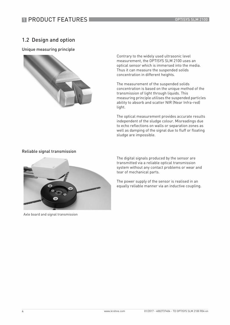
1.2 Design and option
Unique measuring principle
Reliable signal transmission
Contrary to the widely used ultrasonic level measurement, the OPTISYS SLM 2100 uses an optical sensor which is immersed into the media. Thus it can measure the suspended solids concentration in different heights.
The measurement of the suspended solids concentration is based on the unique method of the transmission of light through liquids. This measuring principle utilises the suspended particles ability to absorb and scatter NIR (Near Infra-red) light.
The optical measurement provides accurate results independent of the sludge colour. Misreadings due to echo reflections on walls or separation zones as well as damping of the signal due to fluff or floating sludge are impossible.
The digital signals produced by the sensor are transmitted via a reliable optical transmission system without any contact problems or wear and tear of mechanical parts.
The power supply of the sensor is realised in an equally reliable manner via an inductive coupling.
Axle board and signal transmission
PRODUCT FEATURES 1
5
OPTISYS SLM 2100
www.krohne.com01/2017 - 4002737404 - TD OPTISYS SLM 2100 R04 en
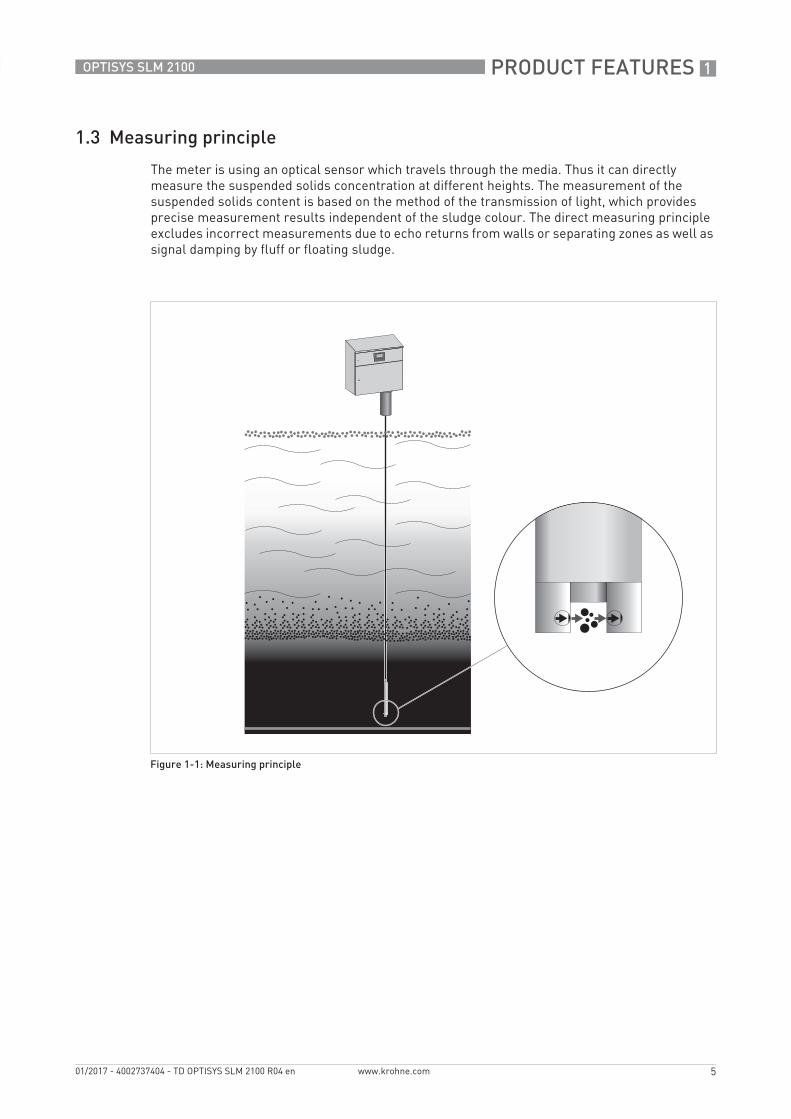
1.3 Measuring principle
The meter is using an optical sensor which travels through the media. Thus it can directly measure the suspended solids concentration at different heights. The measurement of the suspended solids content is based on the method of the transmission of light, which provides precise measurement results independent of the sludge colour. The direct measuring principle excludes incorrect measurements due to echo returns from walls or separating zones as well as signal damping by fluff or floating sludge.
Figure 1-1: Measuring principle

2 TECHNICAL DATA
6
OPTISYS SLM 2100
www.krohne.com 01/2017 - 4002737404 - TD OPTISYS SLM 2100 R04 en
2.1 Technical data
• The following data is provided for general applications. If you require data that is more relevant to your specific application, please contact us or your local sales office.
• Additional information (certificates, special tools, software,...) and complete product documentation can be downloaded free of charge from the website (Downloadcenter).
Measuring systemMeasuring principle Level measurement via immersion of optical sensor with straight
light transmission of NIR-light for suspended solids measurement.
Application range Level measurement of sludge blanket, fluff zone and zone tracking in clarifiers, sedimentation basins as well as in thickeners of water and wastewater treatment plants.
DesignMeasuring range 0.1...30 g/l (depending on the sludge type)
Units Concentration in mg/l or g/l
Height / depth m, cm, feet, inch
Lowering speed sensor Maximal 7.75 cm / 3.05" per second at 50 Hz
Full cycle time for 10 m / 32.8 ft: 3 min
Internal heating "Off" above 8°C / 46.4°F, full power below 4°C / 39.2°F.
Water connection of the cleaning unit (optional)
3/4" connector with metric thread (max. pressure 6 bar / 87 psi)
Display and user interfaceGraphic display LCD display, backlit 128 x 64 pixels, temperature below -25°C / -13°F
may affect the readability of the display
Operating elements 4 push buttons for operator control of the signal converter without opening the housing
Operating menu The operation menu consists of the measuring mode and the menu mode
Measuring mode 2 pages - measuring page with measuring results and status page with status messages
Menu mode Variety of main and submenus that allows customising the device
Operating and display languages English, German, French and Spanish
TECHNICAL DATA 2
7
OPTISYS SLM 2100
www.krohne.com01/2017 - 4002737404 - TD OPTISYS SLM 2100 R04 en
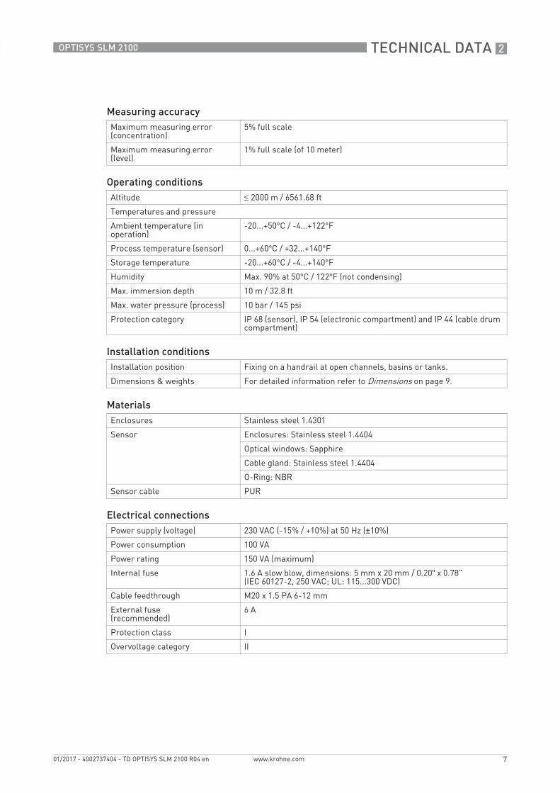
Measuring accuracyMaximum measuring error (concentration)
5% full scale
Maximum measuring error (level)
1% full scale (of 10 meter)
Operating conditionsAltitude ≤ 2000 m / 6561.68 ft
Temperatures and pressure
Ambient temperature (in operation)
-20...+50°C / -4...+122°F
Process temperature (sensor) 0...+60°C / +32...+140°F
Storage temperature -20...+60°C / -4...+140°F
Humidity Max. 90% at 50°C / 122°F (not condensing)
Max. immersion depth 10 m / 32.8 ft
Max. water pressure (process) 10 bar / 145 psi
Protection category IP 68 (sensor), IP 54 (electronic compartment) and IP 44 (cable drum compartment)
Installation conditionsInstallation position Fixing on a handrail at open channels, basins or tanks.
Dimensions & weights For detailed information refer to Dimensions on page 9.
MaterialsEnclosures Stainless steel 1.4301
Sensor Enclosures: Stainless steel 1.4404
Optical windows: Sapphire
Cable gland: Stainless steel 1.4404
O-Ring: NBR
Sensor cable PUR
Electrical connectionsPower supply (voltage) 230 VAC (-15% / +10%) at 50 Hz (±10%)
Power consumption 100 VA
Power rating 150 VA (maximum)
Internal fuse 1.6 A slow blow, dimensions: 5 mm x 20 mm / 0.20” x 0.78" (IEC 60127-2, 250 VAC; UL: 115...300 VDC)
Cable feedthrough M20 x 1.5 PA 6-12 mm
External fuse(recommended)
6 A
Protection class I
Overvoltage category II

2 TECHNICAL DATA
8
OPTISYS SLM 2100
www.krohne.com 01/2017 - 4002737404 - TD OPTISYS SLM 2100 R04 en
Inputs and outputsGeneral All inputs and outputs are electrically isolated from the power supply.
Inputs Control inputs: Three active control inputs, not polarity sensitive
U out = 8 VDC
I out = -10 mA
U low ≤ 2 V
min I typical at 2 V = -8.7 mA
U high ≥ 4 V
max I typical at 4 V = -6.8 mA
Operating modes Control input 1: Rake guard switch or external trigger (switchable via Software)
Control input 2: Rake guard switch or external trigger (switchable via Software)
Control input 3: Maintenance mode
Outputs Current outputs Two outputs (4...20 mA), galvanic isolated from power supply, active mode
Output data Current output A: level of fluff
Current output B: level of sludge blanket or concentration (profile)
Operating data Umax = 18 VDC
I = 4...20 mA
Imax ≤ 22 mA
RL ≤ 550 Ω
Relays Operating modes Relay 1 and 2: Limit switch or status output
Relay 3: Pump protection
Operating data for all relays Uext ≤ 24 VDC/250 VAC
K1 / K2 ≤ 1 AK3 ≤ 0.3 A
Approvals and certificationsCE
The device meets the essential requirements of the EU directives. The CE marking indicates the conformity of the product with the European Union legislation applying to the product and providing for CE marking.
For full information of the EU directives and standards and the approved certifications, please refer to the EU declaration on the website of the manufacturer.

TECHNICAL DATA 2
9
OPTISYS SLM 2100
www.krohne.com01/2017 - 4002737404 - TD OPTISYS SLM 2100 R04 en
2.2 Dimensions
Figure 2-1: Dimensions
Dimensions [mm] Dimensions ["]
a 460 18.11
b 420 16.54
c 195 7.7
d 512 20.16
e 88.5 3.48
f 260 10.24
g 550 21.65
h Ø 85 3.35
j Ø 40 1.57
k 231.5 9.11
2 TECHNICAL DATA
10
OPTISYS SLM 2100
www.krohne.com 01/2017 - 4002737404 - TD OPTISYS SLM 2100 R04 en
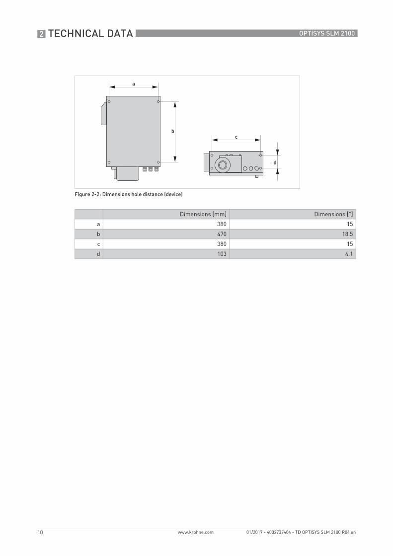
Figure 2-2: Dimensions hole distance (device)
Dimensions [mm] Dimensions ["]
a 380 15
b 470 18.5
c 380 15
d 103 4.1

TECHNICAL DATA 2
11
OPTISYS SLM 2100
www.krohne.com01/2017 - 4002737404 - TD OPTISYS SLM 2100 R04 en
Figure 2-3: Dimensions of mounting frame and cleaning unit
Dimensions [mm] Dimensions ["]
a 109.5 4.31
b 105 4.13
c 175.5 6.91
d 100.5 3.96
e 188.5 7.42
f 376.5 14.82
g 161 6.34
h 152.2 5.9
j 135 5.31
k 127.2 5
e
f
g
h

2 TECHNICAL DATA
12
OPTISYS SLM 2100
www.krohne.com 01/2017 - 4002737404 - TD OPTISYS SLM 2100 R04 en
WeightsWeightsWeightsWeights
Figure 2-4: Hole distance of the mounting
Dimensions [mm] Dimensions ["]
a 607 23.9
b 356 14.0
c 314 12.4
d 71 2.8
e 35.5 1.4
f 50 1.9
g 276 10.8
weight [kg] weight [lbs]
OPTISYS SLM 2100 26.5 58.4
Cleaning unit 4.5 9.9
Mounting frame 3.3 7.3
Rod steel U-bolts and adaptionfor round handrails
1.2 2.6
e
f
g
INSTALLATION 3
13
OPTISYS SLM 2100
www.krohne.com01/2017 - 4002737404 - TD OPTISYS SLM 2100 R04 en
3.1 General notes on installation
3.2 Intended use
The OPTISYS SLM 2100 sludge level meter is primarily designed for use in water and waste water treatment plants. There it determines the sedimentation profile in clarifiers and sludge thickeners and detects sludge blanket or fluff level. For this it measures the suspended solids concentration and height of the sensor above ground as the sensor is lowered into the basin or tank.
However, the design of the OPTISYS SLM 2100 makes it possible to use it in other applications where reliable monitoring of interface or stratification in suspensions is necessary.
The OPTISYS SLM 2100 shall not be used in hazardous areas, which e.g. require Ex approvals. It could ignite gases. Additionally, due to the sensors material, the meter shall not be used in applications with a high concentration of salt (e.g. seawater). The device has been constructed for indoor and outdoor use below the maximum altitude of 2000 m / 6562 ft.
By observing the operation instructions, national standards, safety requirements and accident prevention regulations the residual risk is reduced to an acceptable level.
Inspect the packaging carefully for damages or signs of rough handling. Report damage to the carrier and to the local office of the manufacturer.
Do a check of the packing list to make sure that you have all the elements given in the order.
Look at the device nameplate to ensure that the device is delivered according to your order. Check for the correct supply voltage printed on the nameplate.
3 INSTALLATION
14
OPTISYS SLM 2100
www.krohne.com 01/2017 - 4002737404 - TD OPTISYS SLM 2100 R04 en
3.3 Typical measuring point
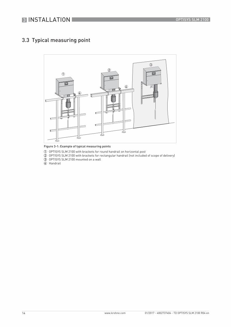
Figure 3-1: Example of typical measuring points
1 OPTISYS SLM 2100 with brackets for round handrail on horizontal post2 OPTISYS SLM 2100 with brackets for rectangular handrail (not included of scope of delivery)3 OPTISYS SLM 2100 mounted on a wall4 Handrail
INSTALLATION 3
15
OPTISYS SLM 2100
www.krohne.com01/2017 - 4002737404 - TD OPTISYS SLM 2100 R04 en
3.4 Installation order
To install the measuring system in the best way, follow the steps described below.
Steps to install the meter1 Mounting of the sludge level meter
(for detailed information refer to the manual of the system).2 Installing the cleaning unit (optional)
(for detailed information refer to the manual of the system)3 Connecting the power supply
(for detailed information refer to the manual of the system).4 Connection of the current outputs
(for detailed information refer to the manual of the system).5 Connecting the rake guard switch / external trigger or maintenance switch - if required
(for detailed information refer to the manual of the system).6 Configuration of the sludge level meter
(for detailed information refer to the manual of the system).7 Calibration of the sludge level meter
(for detailed information refer to the manual of the system).
Do not install the sludge level meter in hazardous areas, it can ignite explosive gases!
Do not cover or obstruct the ventilation. It can lead to overheating of the device.
The device must not be heated by radiated heat (e.g. exposure to the sun) to a electronics housing surface temperature above the maximum permissible ambient temperature. If it is necessary to prevent damage from heat sources, a heat protection (e.g. sun shade) has to be installed.
The operator is responsible for providing, securing and the possibility of switching off the supply voltage.
The external electrical main switch (red / yellow) of the device has to be located close to the device and easily accessible. An internal main switch is not available.
The device should be located at save installation site in order to prevent the danger of falling in the water basin. Furthermore, there should be enough space in front of the device ensuring an easy access.
For decommissioning of the device please repeat the steps above in reverse order from 5 to 1.

3 INSTALLATION
16
OPTISYS SLM 2100
www.krohne.com 01/2017 - 4002737404 - TD OPTISYS SLM 2100 R04 en
3.4.1 Mounting of the sludge level meter
Due to many different applications and installation points of sludge level meter a standardised mounting is often not applicable. To overcome the problem of the local conditions three different opportunities exist to order the mounting of the sludge meter.
Available mounting possibilitiesAvailable mounting possibilitiesAvailable mounting possibilitiesAvailable mounting possibilities
To ensure proper assembly, please use only the mounting material provided with the meter.
All bolts, nuts and washers should be greased to prevent cold welding and ensure simple disassemble after use.
Please ask a second person to help with this procedure.
Ensure that the handrail is suitable for the weight of the mounting frame and the device (standard: 26.5 kg / 58.4 lbs, with cleaning unit: 31kg / 68.3 lbs); otherwise support the handrail with additional material. The operator is responsible for safe installation, especially against the fall in the sedimentation basin.

INSTALLATION 3
17
OPTISYS SLM 2100
www.krohne.com01/2017 - 4002737404 - TD OPTISYS SLM 2100 R04 en
Direct mounting without frameDirect mounting without frameDirect mounting without frameDirect mounting without frame
The sludge meter can be mounted directly on the wall. The sludge level meter has 4 M6 threads on the back and on the bottom of the instrument. If the threads on the bottom are used, ensure that there is enough space for sensor, cable feedthroughs and the cleaning unit. For further information refer to Dimensions on page 9.
• Mount the meter using the 4 M6 screws
Figure 3-2: Mounting on wall
1 4 x M6 screws2 Wall3 OPTISYS SLM 2100
3 INSTALLATION
18
OPTISYS SLM 2100
www.krohne.com 01/2017 - 4002737404 - TD OPTISYS SLM 2100 R04 en
Mounting frameMounting frameMounting frameMounting frame
The mounting frame can be used for round or rectangular handrails. For rectangular handrails suitable rectangular brackets should be selected which are not part of the scope of delivery. Use at least 3 fixation points as described in the installation of round handrails. For further information refer to Dimensions on page 9.
Mounting frame with brackets with round handrail (vertical or horizontal)Mounting frame with brackets with round handrail (vertical or horizontal)Mounting frame with brackets with round handrail (vertical or horizontal)Mounting frame with brackets with round handrail (vertical or horizontal)
This option allows installing the sludge level meter on many round handrails. The rod steel U-bolts cover handrails between diameters of 33...60.3 mm / 1.3...2.37 inch. Two round rod steel U-bolts fixate the mounting frame on the upper handrail. A further rod steel U-bolt stabilises the sludge level meter by fixation to a horizontal or vertical bar.
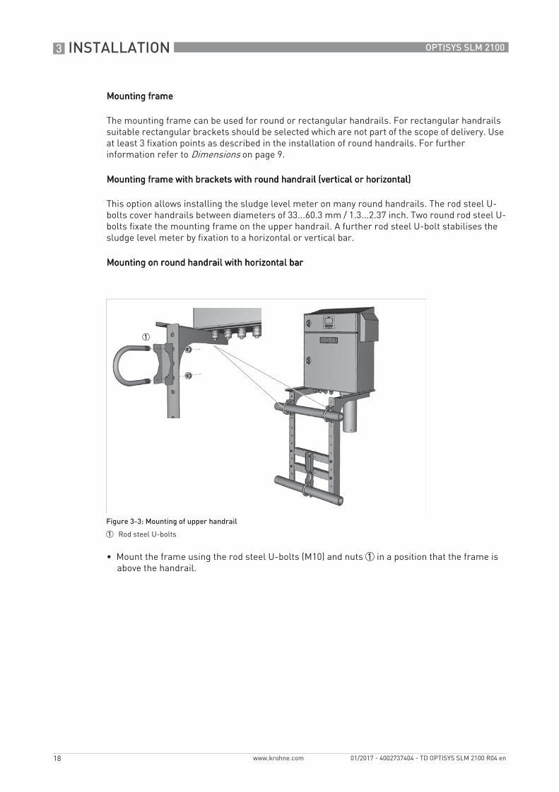
Mounting on round handrail with horizontal barMounting on round handrail with horizontal barMounting on round handrail with horizontal barMounting on round handrail with horizontal bar
• Mount the frame using the rod steel U-bolts (M10) and nuts 1 in a position that the frame is above the handrail.
Figure 3-3: Mounting of upper handrail
1 Rod steel U-bolts

INSTALLATION 3
19
OPTISYS SLM 2100
www.krohne.com01/2017 - 4002737404 - TD OPTISYS SLM 2100 R04 en
Mounting on lower round handrail with horizontal barMounting on lower round handrail with horizontal barMounting on lower round handrail with horizontal barMounting on lower round handrail with horizontal bar
• Find suitable and stable positions of the lower crossbars.• Fix crossbars with screws (M8 x 20), nuts and washers 1.• On both crossbars mount the adaption plate 3.• Mount the rod steel U-bolt (M10) 2 to the horizontal pole with washers.• Use the slot holes to adjust the respective height.• Adjust the position of all brackets.• Tighten all screws.• Position the meter on the frame and tighten it with M6 screws.
Figure 3-4: Mounting of lower handrail (horizontal)
1 Screws and nuts2 Rod steel U-bolt3 Adapter for lower handrail

3 INSTALLATION
20
OPTISYS SLM 2100
www.krohne.com 01/2017 - 4002737404 - TD OPTISYS SLM 2100 R04 en
Mounting on lower round handrail with vertical barMounting on lower round handrail with vertical barMounting on lower round handrail with vertical barMounting on lower round handrail with vertical bar
• Find suitable and stable positions of the lower crossbars.• Fix crossbars with screws and nuts 1.• On one crossbar mount the adaption plate 3.• Mount the rod steel U-bolt 2 to the vertical pole.• Adjust the position of all brackets.• Tighten all screws.• Position the meter on the frame and tighten it with M6 screws.
Figure 3-5: Mounting of lower handrail (vertical)
1 Screws and nuts2 Rod steel U-bolt3 Adapter for lower handrail
INSTALLATION 3
21
OPTISYS SLM 2100
www.krohne.com01/2017 - 4002737404 - TD OPTISYS SLM 2100 R04 en
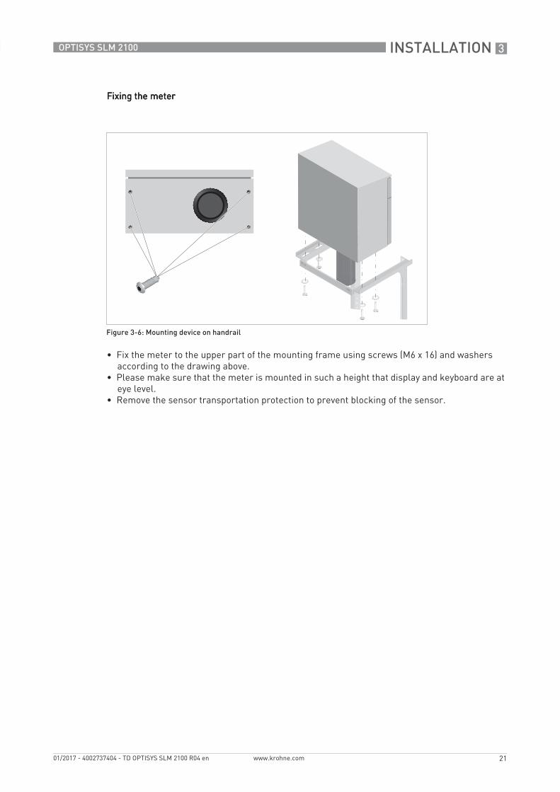
Fixing the meterFixing the meterFixing the meterFixing the meter
• Fix the meter to the upper part of the mounting frame using screws (M6 x 16) and washers according to the drawing above.
• Please make sure that the meter is mounted in such a height that display and keyboard are at eye level.
• Remove the sensor transportation protection to prevent blocking of the sensor.
Figure 3-6: Mounting device on handrail

3 INSTALLATION
22
OPTISYS SLM 2100
www.krohne.com 01/2017 - 4002737404 - TD OPTISYS SLM 2100 R04 en
3.5 Installing the cleaning unit (optional)
The cleaning unit, mounted under the device, consists of a valve and a spraying system to keep the sensor and cable free of deposits ensuring low maintenance efforts of the device. The cleaning unit is mounted and electrically connected to the device by the manufacturer with exception of the spray shield and the water connection.
If installing a device containing a cleaning unit, keep a safety area around the sensor garage free from electrical device or water sensitive parts, as outlined in the following drawing.
The cleaning unit can be supplied with water by 2 options:• External water supply by hose with drinking or process water.• Water supplied by pumped clear water of the sedimentation basin. For further information
refer to Description and properties of the relays on page 38.
Figure 3-7: Safety area
1 Radius: 2 m / 78.74"

INSTALLATION 3
23
OPTISYS SLM 2100
www.krohne.com01/2017 - 4002737404 - TD OPTISYS SLM 2100 R04 en
3.5.1 Installation of the water hose to cleaning unit
A 3/4" male connector (Whitworth EN 10226) with metric thread provides the mounting junction for the water hose adapter.
When installing the water hose adapter on the connector, carefully fix the nut of the fitting. The electric valve inside the cleaning system housing may be twisted, which may cause water leakage.
When installing the device, make sure the water hose is adequately fixed as outlined. Mount the water hose in such a way that the weight of it is not carried by the hose adapter. When fixing the hose also take into account that it must be avoided that it moves when the system is switched on/off.
The maximum allowed water pressure should not exceed 6 bar / 87 psi.
An external separation switch of the water supply has to be located close to the device and easily accessible.
Figure 3-8: Fixing points water hose
1 Water hose2 Fixing points
3 INSTALLATION
24
OPTISYS SLM 2100
www.krohne.com 01/2017 - 4002737404 - TD OPTISYS SLM 2100 R04 en
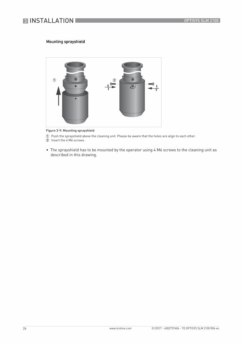
Mounting sprayshieldMounting sprayshieldMounting sprayshieldMounting sprayshield
• The sprayshield has to be mounted by the operator using 4 M6 screws to the cleaning unit as described in this drawing.
Figure 3-9: Mounting sprayshield
1 Push the sprayshield above the cleaning unit. Please be aware that the holes are align to each other.2 Insert the 4 M6 screws.

ELECTRICAL CONNECTIONS 4
25
OPTISYS SLM 2100
www.krohne.com01/2017 - 4002737404 - TD OPTISYS SLM 2100 R04 en
4.1 Safety instructions
4.2 Used abbreviations
All work on the electrical connections may only be carried out with the power disconnected. Take note of the voltage data on the nameplate!
Observe the national regulations for electrical installations!
Observe without fail the local occupational health and safety regulations. Any work done on the electrical components of the measuring device may only be carried out by properly trained specialists.
Before performing any work on the device switch off the power and make sure that it cannot be switched on accidently.
Look at the device nameplate to ensure that the device is delivered according to your order. Check for the correct supply voltage printed on the nameplate.
Abbreviation Description
CIa Control input active
Ia Current output active
Imax Maximum current
Inom Nominal current
RL Load resistance
P Power
Uint, nom Nominal internal voltage
Uext External voltage
Uo Terminal voltage
VAC Alternating current (AC) voltage
CI Control input
PCS Process control system
NO Switch (normally open)
NC Switch (normally closed)
LED Light-emitting diode
K Relay

4 ELECTRICAL CONNECTIONS
26
OPTISYS SLM 2100
www.krohne.com 01/2017 - 4002737404 - TD OPTISYS SLM 2100 R04 en
4.3 Description of electrical symbols
Symbol Description
Ampere meter, 0...20 mA or 4...20 mA, RL is the internal resistance of the measuring point including the cable resistance
Internal direct current (DC) voltage source
Controlled internal current source in the device
Switch, NO contact or similar
Input, galvanically insulated
Positive temperature coefficient (PTC) resistance
LED
Protection switch
Grounding
Motor
Heater
Fan

ELECTRICAL CONNECTIONS 4
27
OPTISYS SLM 2100
www.krohne.com01/2017 - 4002737404 - TD OPTISYS SLM 2100 R04 en
4.4 Important device-specific notes on electrical connection
Valve
Pump
Limit switch
Symbol Description
Never install or operate the device in potentially explosive areas, it might cause an explosion that can result in fatal injuries!
The device must be grounded in accordance with regulations in order to protect personnel against electric shocks.
When installing and wiring the device, note the safety regulations of the current state of the art. Also note the following items to avoid fatal injuries, destruction or damage of the device or measuring errors:
• De-energise the cables of the power supply before you start any installation works!• All used cables must have a corresponding dielectric strength of min. 2 kV.• It is recommended to use shielded signal cables which are only connected on one side (e.g. to
the protective earth on the mainboard next to the relays).• If relays are used, note that with inductive loads the interference must be suppressed (spark
quenching).• Assure that all electrical connection works are compliant with the VDE 0100 directive
"Regulations for electrical power installations with line voltages up to 1000 V" or equivalent national regulations.
• Use suitable cable glands for the various electrical cables and suitable connecting cables for the field of application. The outer diameter of the connecting cables has to fit to the cable glands.
• The nominal voltage of the connecting cable has to fit to the operating voltage of the device.
• If the handrail is not adequately grounded, ground the device with a wire of 6 mm2 / 10 AWG (American Wire Gauge).
Assembly materials and tools are not part of the delivery. Use the assembly materials and tools in compliance with the applicable occupational health and safety directives.

4 ELECTRICAL CONNECTIONS
28
OPTISYS SLM 2100
www.krohne.com 01/2017 - 4002737404 - TD OPTISYS SLM 2100 R04 en
4.5 Overview of cable connections
In the bottom lower left corner of the enclosure there are 4 cable feedthrough connections as cable feedthroughs to the electronics compartment (if the cleaning unit is used only 3 feedthroughs are available). All connected cables have to be installed via these feedthroughs.
After feeding the cables through the feedthroughs they are run in the cable guide to the bottom of the electronics compartment where they need to be fed into another cable guide in order to be routed further to the connectors at the mainboard.
When installing and wiring the device, note the safety regulations of the current state of the art. Also note the following items to avoid fatal injuries, destruction or damage of the device or measuring errors:
• Do not run cables on pathways. Regularly check the cable runs for loose cables hanging into footpaths.
• Before connecting main power, all connectors at the connecting terminal need to be plugged.• Please pay attention to the front doors. Make sure that the doors do not shut if hands or tools
are inside the meter. Otherwise the sharp edges of the doors can cause fatal injuries or damage to the equipment.
In order to assure proper sealing of the cable feedthrough only cables with a diameter between 6...12 mm / 0.24...0.47 inch should be used.
Figure 4-1: Overview of cable connections
1 4 x M20 cable feedthroughs (if the cleaning unit is used only 3 feedthroughs are available)2 Cable guides3 Mainboard with connector blocks
ELECTRICAL CONNECTIONS 4
29
OPTISYS SLM 2100
www.krohne.com01/2017 - 4002737404 - TD OPTISYS SLM 2100 R04 en
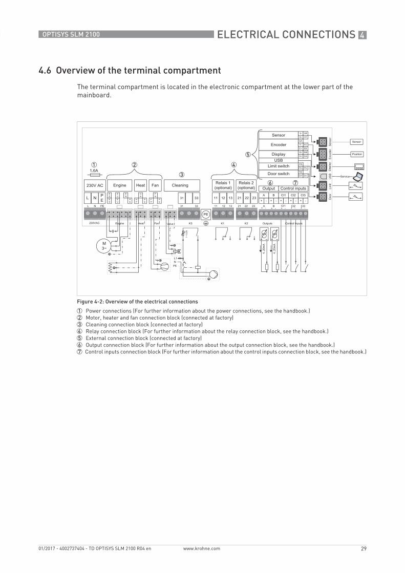
4.6 Overview of the terminal compartment
The terminal compartment is located in the electronic compartment at the lower part of the mainboard.
Figure 4-2: Overview of the electrical connections
1 Power connections (For further information about the power connections, see the handbook.)2 Motor, heater and fan connection block (connected at factory)3 Cleaning connection block (connected at factory)4 Relay connection block (For further information about the relay connection block, see the handbook.)5 External connection block (connected at factory)6 Output connection block (For further information about the output connection block, see the handbook.)7 Control inputs connection block (For further information about the control inputs connection block, see the handbook.)

4 ELECTRICAL CONNECTIONS
30
OPTISYS SLM 2100
www.krohne.com 01/2017 - 4002737404 - TD OPTISYS SLM 2100 R04 en
4.7 Connecting the power supply
Never install or operate the device in potentially explosive areas, it might cause an explosion that can result in fatal injuries!
The device must be grounded in accordance with regulations in order to protect personnel against electric shocks.
When connecting the power supply, always note the safety regulations of the current state of the art. To avoid fatal injuries, destruction or damage of the device or measuring errors, also note the following items:
• De-energise the cables of the power supply before you start any installation works!
• Ground the device (cross section of the wire is 6 mm2 / 10 AWG).• The device must be led over a ground fault circuit interrupter (GFCI) 0.03 A which has to be
tested every 6 months.• Inspect the continuous PE conductor connection to all contactable metal parts by carrying out
a standardised procedure (The maximum allowed resistance is 0.5 Ohm).• Assure that there is a fuse protection for the infeed power circuit (Inom ≤ 6 A).
• Check the nameplate and assure that the power supply meets the voltage and frequency of the device. The device can be operated with 230 VAC (-15/+10%) at 50 Hz (±10%) and max. 150 VA. A power supply outside these specifications may destroy the device!
• Assure that the protective earth conductor (PE) is approx. 5 mm / 0.20" longer than the L- and N-conductor.
The operator is responsible for providing, securing and the possibility for switching off the supply voltage.

ELECTRICAL CONNECTIONS 4
31
OPTISYS SLM 2100
www.krohne.com01/2017 - 4002737404 - TD OPTISYS SLM 2100 R04 en
Before you start to connect the power supply cables, note the following drawing with the function of the terminals:
Figure 4-3: Connecting power supply
1 Live (L)2 Neutral (N)3 Protective earth (PE)
All cables must have a test voltage of min. 2 kV and an appropriate outer insulation (additional to the insulation of the individual wire). The outer insulation should be removed 40 mm / 1.57". The minimum cross section of the wires is 1.5 mm2 / 16 AWG and the maximum is 2.5 mm2 / 12 AWG.
In order to assure proper sealing of the cable feedthrough only cables with a diameter between 6...12 mm / 0.24...0.47 inch should be used.
The device contains an internal fuse (1.6 A slow blow). Replacement of the fuse should only be carried out by a service technician.
4 ELECTRICAL CONNECTIONS
32
OPTISYS SLM 2100
www.krohne.com 01/2017 - 4002737404 - TD OPTISYS SLM 2100 R04 en
4.8 Description and properties of the output and the input
4.8.1 Current output
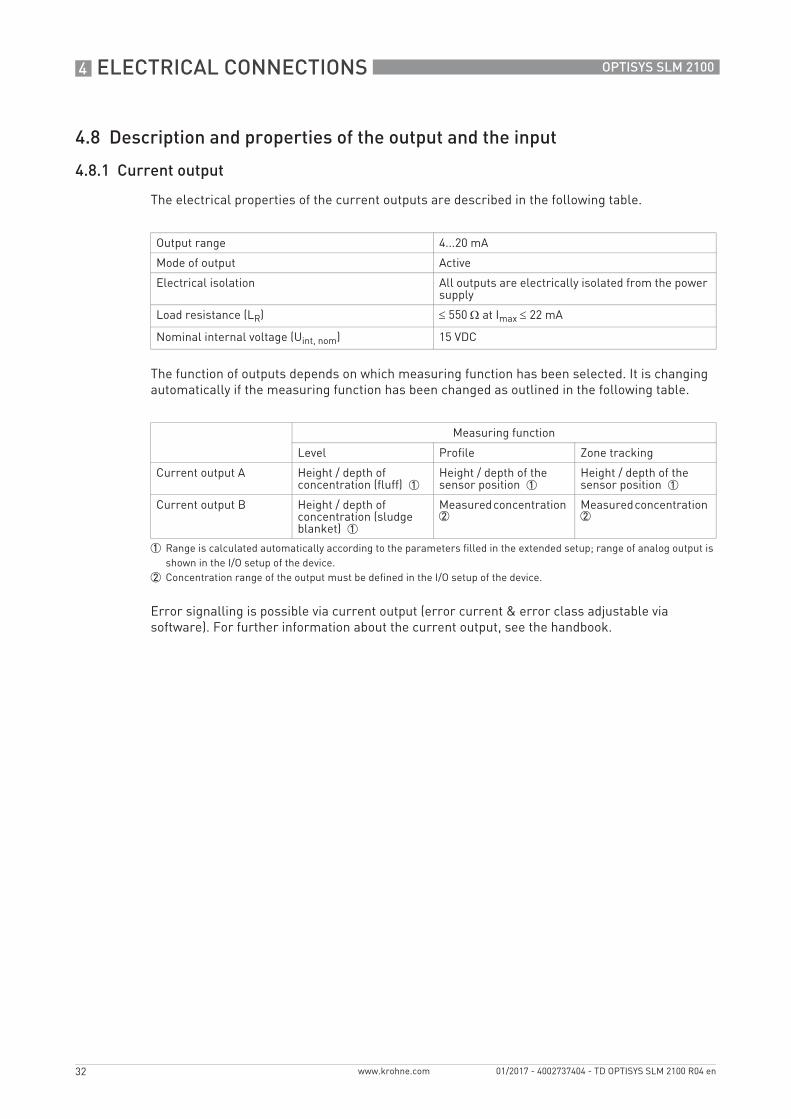
The electrical properties of the current outputs are described in the following table.
The function of outputs depends on which measuring function has been selected. It is changing automatically if the measuring function has been changed as outlined in the following table.
Error signalling is possible via current output (error current & error class adjustable via software). For further information about the current output, see the handbook.
Output range 4...20 mA
Mode of output Active
Electrical isolation All outputs are electrically isolated from the power supply
Load resistance (LR) ≤ 550 Ω at Imax ≤ 22 mA
Nominal internal voltage (Uint, nom) 15 VDC
Measuring function
Level Profile Zone tracking
Current output A Height / depth of concentration (fluff) 1
Height / depth of the sensor position 1
Height / depth of the sensor position 1
Current output B Height / depth of concentration (sludge blanket) 1
Measured concentration 2
Measured concentration 2
1 Range is calculated automatically according to the parameters filled in the extended setup; range of analog output is shown in the I/O setup of the device.
2 Concentration range of the output must be defined in the I/O setup of the device.

ELECTRICAL CONNECTIONS 4
33
OPTISYS SLM 2100
www.krohne.com01/2017 - 4002737404 - TD OPTISYS SLM 2100 R04 en
4.8.2 Control input (active)
The electrical properties of the 3 control inputs (CI) in detail are the following:
Function of the control inputsFunction of the control inputsFunction of the control inputsFunction of the control inputs
The three active control inputs can trigger different events in the meter from outside. They are engaged via simple contact closure of an external contact.
The 3 control inputs (CI) have the following functions:
• Control input 1: Rake guard switch or external trigger (selectable via software)• Control input 2: Rake guard switch or external trigger (selectable via software)• Control input 3: Maintenance mode
Rake guard switchRake guard switchRake guard switchRake guard switch
To protect the sensor and cable from being damaged or destructed by rakes or other moving parts, the control input 1 and 2 can be used. For this purpose a NO switch has to be connected to CI 1 / 2 (Note the switch is not part of the scope of delivery. The additional part has to be purchased from another manufacturer). In case CI 1 / 2 is set to rake guard switch, the sampling will be interrupted and the sensor hauled back as soon as the external contact is closed.
External triggerExternal triggerExternal triggerExternal trigger
The function of the external trigger is to trigger the sampling process. For this purpose a NO switch has to be connected to CI 1 / 2 (Note the switch is not part of the scope of delivery. The additional part has to be purchased from another manufacturer). In case CI 1 / 2 is set to external trigger mode the sampling cycle will start as soon as the external contact is closed.
The factory default is a disabled control input!
Mode of input Active, not polarity sensitive
Maximal voltage (Umax) 15 VDC
Voltage out (U out) 8 VDC
Current out (I out) -10 mA
Voltage low (U low) < 2 V
Voltage high ( U high) > 4 V
To avoid damages or destructions, use a limit rake guard switch in all applications where a rake or other moving devices may come in contact with the sensor or cable! The manufacturer does not assume any responsibility for damages caused by the absence or malfunction of the rake guard limit switch.

4 ELECTRICAL CONNECTIONS
34
OPTISYS SLM 2100
www.krohne.com 01/2017 - 4002737404 - TD OPTISYS SLM 2100 R04 en
Maintenance modeMaintenance modeMaintenance modeMaintenance mode
The function of the maintenance mode is to set the device to maintenance mode in order to enable easy cleaning of sensor, cable and meter. For this purpose a NO switch has to be connected to CI 3 (Note the switch is not part of the scope of delivery. The additional part has to be purchased from another manufacturer). In case CI 3 is activated the sampling cycle will be interrupted and the sensor is hauled back to the home position as soon as the external contact is closed. After that, the current outputs are frozen and the sensor can be moved by the simple push of the arrow buttons on the keypad.
4.9 Connection of output and input
4.9.1 Important notes
Never install or operate the device in potentially explosive areas, it might cause an explosion that can result in fatal injuries.
• The inputs/outputs must be connected passively or actively or acc. to EN 60947-5-6.• Active operating mode: the signal converter supplies the power for operation (activation) of
the subsequent devices, observe max. operating data.• Terminals that are not used must not have any conductive connection to other electrically
conductive parts.

ELECTRICAL CONNECTIONS 4
35
OPTISYS SLM 2100
www.krohne.com01/2017 - 4002737404 - TD OPTISYS SLM 2100 R04 en
4.9.2 Current output
The terminals for the connection of the two current outputs are located on the mainboard. Please refer to the following diagram for proper connection of the cables.
All work on the electrical connections may only be carried out with the power disconnected.
To avoid damage or destruction of the device always note the following items:• Observe the connection polarity!• Note the properties of the current output; for further information refer to Technical data on
page 6.
Assembly materials and tools are not part of the delivery. Use the assembly materials and tools in compliance with the applicable occupational health and safety directives.
Connection diagram of current output (active)
Figure 4-4: Current output (active)
Figure 4-5: Connection current output
1 Current output A2 Current output B
The correct connection of the current outputs takes place with the help of shielded signal cables which are approved for the rated current and voltage.
All cables must have a test voltage of min. 2 kV and an appropriate outer insulation (additional to the insulation of the individual wire) . The outer insulation should be removed 30...50 mm / 1.18...1.97 inch. The minimum allowed cross section of the wires is 0.5 mm2 / 20 AWG and the maximum is 1.5 mm2 / 16 AWG.

4 ELECTRICAL CONNECTIONS
36
OPTISYS SLM 2100
www.krohne.com 01/2017 - 4002737404 - TD OPTISYS SLM 2100 R04 en
• Open the cable drum and electronic compartment door.• Push the prepared cables through the cable feedthrough and route them to the electronic
compartment (for more information refer to Overview of cable connections on page 28).• Connect the positive and negative lead according to the connection diagrams above.• Connect the shield to one side only (e.g. to the protective earth on the mainboard next to the
relay) side.• Tighten the screw connection of the cable feedthrough securely.• Seal all cable feedthrough that are not needed with a plug.• Close both compartment doors
4.9.3 Electrical connection of control inputs
The terminals for the connection of the three control inputs are located on the mainboard. Please refer to the following diagram for proper connection of the cables.
In order to assure proper sealing of the cable feedthrough only cables with a diameter between 6...12 mm / 0.24...0.47 inch should be used.
All work on the electrical connections may only be carried out with the power disconnected.
To avoid damage or destruction of the device always note the properties of the control input; for further information refer to Technical data on page 6.
Assembly materials and tools are not part of the delivery. Use the assembly materials and tools in compliance with the applicable occupational health and safety directives.
All cables must have a test voltage of min. 2 kV and an appropriate outer insulation (additional to the insulation of the individual wire) . The outer insulation should be removed 30...50 mm / 1.18...1.97 inch. The minimum allowed cross section of the wires is 0.5 mm2 / 20 AWG and the maximum is 1.5 mm2 / 16 AWG.
Figure 4-6: Control input
1 Signal

ELECTRICAL CONNECTIONS 4
37
OPTISYS SLM 2100
www.krohne.com01/2017 - 4002737404 - TD OPTISYS SLM 2100 R04 en
Connecting the control inputs• Open the cable drum and electronic compartment door.• Push the prepared cables through the cable feedthrough and route them to the electronic
compartment (for more information refer to Overview of cable connections on page 28).• Connect the positive and negative lead according to the connection diagrams above.• Connect the shield to one side only e.g. on PCS (process control system) side.• Tighten the screw connection of the cable feedthrough securely.• Seal all cable feedthroughs that are not needed with a plug.• Close both compartment doors.
Figure 4-7: Connection control input
1 Control input (CI1)2 Control input (CI2)3 Control input (CI3)
In order to assure proper sealing of the cable feedthrough only cables with a diameter between 6...12 mm / 0.24...0.47 inch should be used.

4 ELECTRICAL CONNECTIONS
38
OPTISYS SLM 2100
www.krohne.com 01/2017 - 4002737404 - TD OPTISYS SLM 2100 R04 en
4.10 Description and properties of the relays
The electrical properties of the relays in detail are the following:
The devices contains 3 relays. Two relays (K1 &K2) can be either configured as limit switch or as status output. The third relay (K3) is reserved for the pump controller of the cleaning unit.
Status output:If an error of the selected class occurs the relays remains active, until the error is cleared by the user or the device is leaving the error state automatically.
Limit switch:When the relay is configured as limit switch the limit parameter used is the sensor position (height / depth). The relays can work as limit switch only in level and zone tracking mode. The parameter "direction" defines the trigger for the relay, which means the relay is switched either when the sensor position about limit value or the sensor position below limit. The hysteresis defines the sensor position, where the limit switch (relay) is reset, relatively to the selected threshold. Combining the parameters threshold and hysteresis a range can be defined, where the limit switch is active. The relay configuration menus can be found in the setup I/O menu. For further information about the limit switch, see the handbook..
Pump controller:The pump in the clear water phase of the sedimentation basis can be controlled. The pump connector should be connected to the device only if the external pump is used to transport the cleaning medium. A pump lead time, programmable via menu, can be used to delay the sensor cleaning process until pump system pressure has been setup.
Never install or operate the device in potentially explosive areas, it might cause an explosion that can result in fatal injuries.
Maximal external voltage (Uext) 24 VDC / 250 VAC
Maximal current (I) K1 / K2 ≤ 1 AK3 ≤ 0.3 A

ELECTRICAL CONNECTIONS 4
39
OPTISYS SLM 2100
www.krohne.com01/2017 - 4002737404 - TD OPTISYS SLM 2100 R04 en
4.10.1 Connection of the relays
The terminals for the connection of the two relays (K1 & K2) are located on the mainboard. Please refer to the following diagram for proper connection of the cables.
Never connect an external water pump directly to the sludge level meter connector K3, the output connector is only specified as a control output for a motor protection.
All work on the electrical connections may only be carried out with the power disconnected.
Assembly materials and tools are not part of the delivery. Use the assembly materials and tools in compliance with the applicable occupational health and safety directives.
The correct connection of the relays may only be ensured by using signal cables which are approved for the rated current and voltage.
All cables must have a test voltage of min. 2 kV and an appropriate outer insulation (additional to the insulation of the individual wire). The outer insulation should be removed 40 mm / 1.57". The minimum cross section of the wires is 1.5 mm2 / 16 AWG and the maximum is 2.5 mm2 / 12 AWG.
In order to assure proper sealing of the cable feedthrough only cables with a diameter between 6...12 mm / 0.24...0.47 inch should be used.
Figure 4-8: Connection diagram of relays K1 and K2
1 LED2 Voltage source

4 ELECTRICAL CONNECTIONS
40
OPTISYS SLM 2100
www.krohne.com 01/2017 - 4002737404 - TD OPTISYS SLM 2100 R04 en
The pump connector should be only connected to the OTPISYS SLM 2100 if the external pump is used as cleaning medium. The terminal connection is outlined in the following diagram.
For installation of the relays follow the steps below:• Move the sensor by using the manual operation in the home position and turn off the power of
the instrument.• Open the cable drum and electronics compartment doors.• Push the prepared cables through the cable feed through and route them to the electronic
compartment.• Connect the positive and negative lead according to the connection diagrams above.• Connect the shield to one side only e.g. on PCS (process control system) side.• Tighten the screw connection of the cable entries securely.• Seal all cable entries that are not needed with a plug.• Close both compartment doors.
4.11 Protection category
IP 68 (sensor), IP 54 (electronic compartment), IP 44 (cable drum compartment).
Figure 4-9: Connection diagram pump (K3)
1 External voltage2 PTC resistance (Imax = 0.3 A)
Do not install the sludge blanket meter in hazardous areas, it can ignite explosive gases!

ORDER INFORMATION 5
41
OPTISYS SLM 2100
www.krohne.com01/2017 - 4002737404 - TD OPTISYS SLM 2100 R04 en
5.1 Order code
The characters of the order code highlighted in light grey describe the standard.
VGA XVGA XVGA XVGA X 4444 Type/Housing converterType/Housing converterType/Housing converterType/Housing converter
2 OPTISYS SLM 2100 Sludge level meter
Measuring rangeMeasuring rangeMeasuring rangeMeasuring range
A 0...10 m / 0.1...30 g/l
FeaturesFeaturesFeaturesFeatures
1 Standard
2 Cleaning unit
Process conditionsProcess conditionsProcess conditionsProcess conditions
A -20...+50°C / -4...+122°F
Signal outputsSignal outputsSignal outputsSignal outputs
2 2 x 4...20 mA current outputs
RelaysRelaysRelaysRelays
A 2 x Relays (programmable)
Operation languageOperation languageOperation languageOperation language
A English
B German
C French
D Spanish
Power supplyPower supplyPower supplyPower supply
1 230 VAC / 50 Hz
OptionsOptionsOptionsOptions
0 none
1 Mounting frame without fixation
A Hand rail mounting set for round handrails
DocumentationDocumentationDocumentationDocumentation
0 None
1 English
2 German
3 French
4 Spanish
VGA XVGA XVGA XVGA X 4444 Order code
5 ORDER INFORMATION
42
OPTISYS SLM 2100
www.krohne.com 01/2017 - 4002737404 - TD OPTISYS SLM 2100 R04 en
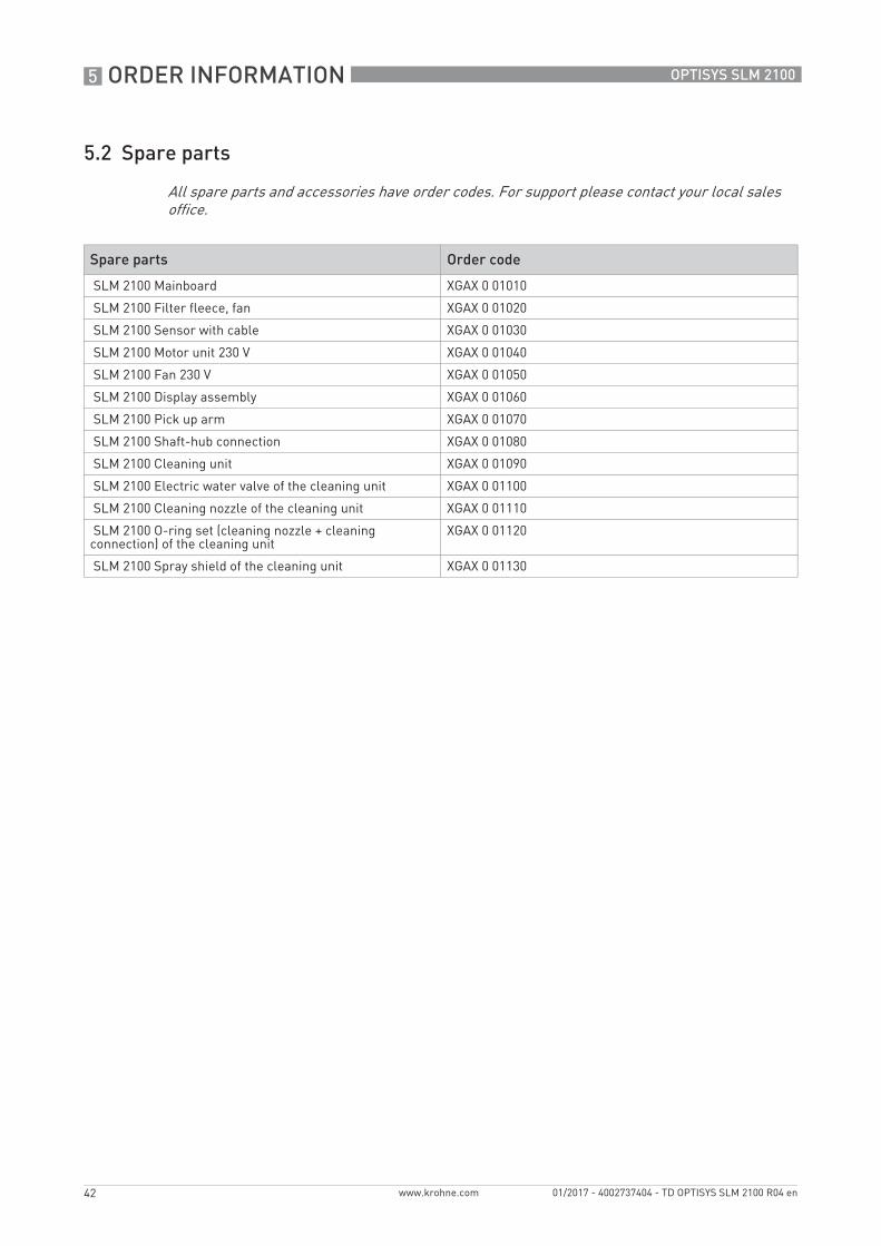
5.2 Spare parts
All spare parts and accessories have order codes. For support please contact your local sales office.
Spare parts Order code
SLM 2100 Mainboard XGAX 0 01010
SLM 2100 Filter fleece, fan XGAX 0 01020
SLM 2100 Sensor with cable XGAX 0 01030
SLM 2100 Motor unit 230 V XGAX 0 01040
SLM 2100 Fan 230 V XGAX 0 01050
SLM 2100 Display assembly XGAX 0 01060
SLM 2100 Pick up arm XGAX 0 01070
SLM 2100 Shaft-hub connection XGAX 0 01080
SLM 2100 Cleaning unit XGAX 0 01090
SLM 2100 Electric water valve of the cleaning unit XGAX 0 01100
SLM 2100 Cleaning nozzle of the cleaning unit XGAX 0 01110
SLM 2100 O-ring set (cleaning nozzle + cleaning connection) of the cleaning unit
XGAX 0 01120
SLM 2100 Spray shield of the cleaning unit XGAX 0 01130

NOTES 6
43
OPTISYS SLM 2100
www.krohne.com01/2017 - 4002737404 - TD OPTISYS SLM 2100 R04 en

KROHNE – Process instrumentation and measurement solutions
• Flow
• Level
• Temperature
• Pressure
• Process Analysis
• Services
Head Office KROHNE Messtechnik GmbHLudwig-Krohne-Str. 547058 Duisburg (Germany)Tel.: +49 203 301 0Fax: +49 203 301 [email protected]
© K
RO
HN
E 01
/201
7 -
4002
7374
04 -
TD
OP
TISY
S SL
M 2
100
R04
en
- Su
bjec
t to
chan
ge w
ithou
t not
ice.
The current list of all KROHNE contacts and addresses can be found at:www.krohne.com
KK
K