Embed Size (px)
Citation preview
28563AA
Please carefully read these instructions before using this product.Save this manual for future use.
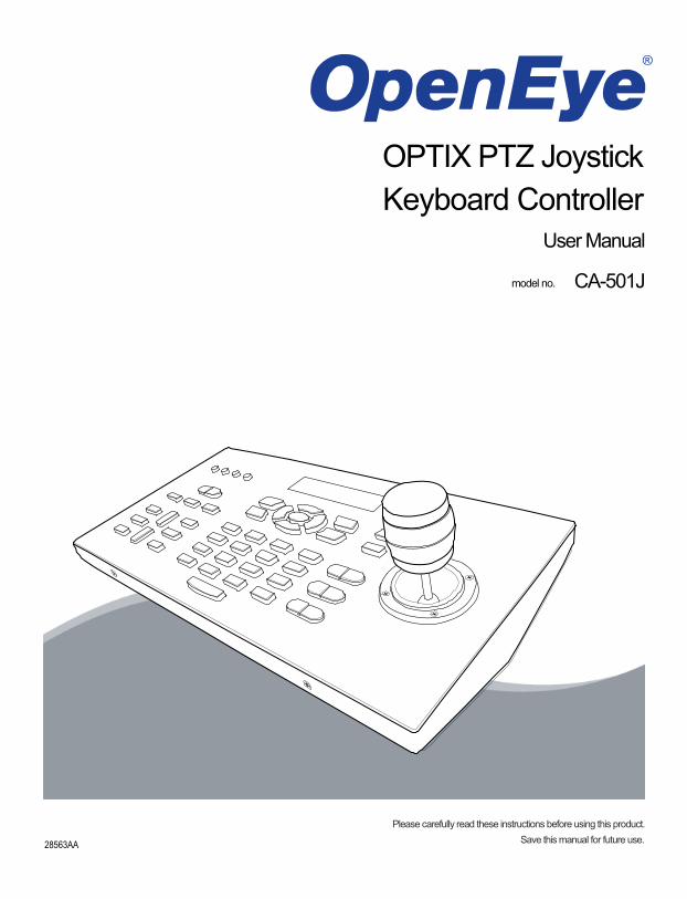
OPTIX PTZ JoystickKeyboard Controller
User Manual
model no.model no. CA-501J

ii 28563AA
28563AA iii
PTZ Keyboard Controller
User Guide
Manual Edition 28563AA – JANUARY 2008
©2000-2008, OPENEYE INC All Rights Reserved.
No part of this documentation may be reproduced in any means, electronic or mechanical, for any purpose, except as expressed inthe Software License Agreement. Openeye shall not be liable for technical or editorial errors or omissions contained herein. Theinformation in this document is subject to change without notice.
THE INFORMATION IN THIS PUBLICATION IS PROVIDED “AS IS” WITHOUT WARRANTY OF ANY KIND. THE ENTIRE RISK ARISING OUT OF THE USE OF THIS INFORMATION REMAINS WITH RECIPIENT. IN NO EVENT SHALL OPENEYE BE LIABLE FOR ANY DIRECT, CONSEQUENTIAL, INCIDENTAL, SPECIAL, PUNITIVE, OR OTHER DAMAGES WHATSOEVER (INCLUDING WITHOUT LIMITATION, DAMAGES FOR LOSS OF BUSINESS PROFITS, BUSINESS INTERRUPTION OR LOSS OF BUSINESS INFORMATION), EVEN IF OPENEYE HAS BEEN ADVISED OF THE POSSIBILITY OF SUCH DAMAGES AND WHETHER IN AN ACTION OR CONTRACT OR TORT, INCLUDING NEGLIGENCE.
This software and documentation are copyrighted. All other rights, including ownership of the software, are reserved to OPENEYEINCORPORATED. OPENEYE, Openeye, HDDR, and High Definition Digital Recorder are registered trademarks of OPENEYE INCORPORATED in the United States and elsewhere; Windows, and Windows XP Embedded are registered trademarks of Microsoft Corporation. All other brand and product names are trademarks or registered trademarks of the respective owners.
The following words and symbols mark special messages throughout this guide:
WARNING: Text set off in this manner indicates that failure to follow directions could result in bodily harm or loss of life.
CAUTION: Text set off in this manner indicates that failure to follow directions could result in damage to equipment or loss of information.
OPENEYE INCORPORATED Liberty Lake, WA � U.S.A.
iv 28563AA
IMPORTANT SAFEGUARDS
1. Read Owner’s Manual – After unpacking this product, read the owner’s manual carefully, and follow all the operating and other instruction
2. Power Sources – This product should be operated only from the type of power source indicated on the label. If you are not sure of the type of power supply to your home or business, consult your product dealer or local power company
3. Ventilation – Slots and openings in the cabinet are provided for ventilation and to ensure reliable operation of the product and to protect it from overheating These openings must not be blocked or covered. The product should not be placed in a built-in installation such as a bookcase or rack unless proper ventilation is provided or the manufacturer’s instructions have been adhered to.
4. Heat – This product should not be used near heat sources such as radiators, heat registers, stoves, or other products that produce heat.
5. Water and Moisture – Do not use this product near water. Do not exceed the humidity specifications for the product as detailed in the Appendix section in this manual
6. Cleaning – Unplug this product from the wall outlet before cleaning. Do not use liquid cleaners or aerosol cleaners. Use a damp cloth for cleaning.
7. Power Cord Protection – Power-supply cords should be routed so that they are not likely to be walked on or pinched by items placed against them, paying particular attention to cords at plugs, convenience receptacles, and the point where they exit from the product.
8. Overloading – Do not overload wall outlets; extension cords, or integral convenience receptacles as this can result in a risk of fire or electrical shock.
9. Lightning – For added protection during storms or when it is left unattended and unused for long periods of time, unplug it from the wall outlet. This will prevent damage to the product due to lightning and power line surges.
10. Object and Liquid Entry Points – Never insert foreign objects into the Joystick Controller, other than the media types approved by Openeye, as they may touch dangerous voltage points or short-out parts that could result in a fire or electrical shock. Never spill liquid of any kind on the product.
11. Accessories – Do not place this product on an unstable cart, stand, tripod, bracket, or table. The product may fall, causing serious personal injury and serious damage to the product.
12. Burden – Do not place heavy objects on or step on the product. The object may fall, causing serious personal injury and serious damage to the product.
28563AA v
IMPORTANT SAFEGUARDS, continued
13. Damage Requiring Service – Unplug the unit from the outlet and refer servicing to qualified service personnel under the following conditions: When the power-supply cord or plug is damaged. If liquid has been spilled, or objects have fallen into the unit. If the unit has been exposed to rain or water. If the unit does not operate normally by following the operating instructions. Adjust only those controls that are covered by the operating instructions as an improper adjustment of other controls may result in damage and will often require extensive work by a qualified technician to restore the unit to its normal operation. If the unit has been dropped or the enclosure has been damaged. When the unit exhibits a distinct change in performance - this indicates a need for service.
14. Servicing – Do not attempt to service this product yourself. Opening or removing cover may expose you to dangerous voltage or other hazards. Refer all servicing to qualified personnel.
15. Replacement Parts – When replacement parts are required, be sure the service technician has used replacement parts specified by the manufacturer or have the same characteristics as the original part. Unauthorized substitutions may result in fire, electric shock or other hazards.
16. Safety Check – Upon completion of any service or repairs to this unit, ask the service technician to perform safety checks to determine that the unit is in proper operating condition.
NOTES ON HANDLING
When shipping the Joystick Controller, the original shipping carton packing materials come in handy. For maximum protection, repack the unit as it was originally packed at the factory.
Do not use volatile liquids, such as insect spray, near the Video Sever unit. Do not leave rubber or plastic products in contact with the Joystick Controller for long periods of time. Doing so may result in permanent marks on the Joystick Controller.
The top and rear panels of the Joystick Controller may become warm after long periods of use. This is not a malfunction.
NOTES ON LOCATING
Place the Joystick Controller on a level surface. Do not use it on a shaky or unstable surface such as a wobbling table or inclined stand.
When you place this Joystick Controller next to a TV, radio, or VCR, the playback picture may become poor and the sound may be distorted. If this happens, move the Joystick Controller away from the TV, radio, or VCR.
vi 28563AA
NOTES ON CLEANING
Use a soft dry cloth for cleaning.
For stubborn dirt, soak the cloth in a weak detergent solution, wring well and wipe. Use a dry cloth to wipe it dry. Do not use any type of solvent, such as thinner and benzene, as they may damage the surface of the Joystick Controller.
If you use a chemical saturated cloth to clean the unit, follow that product’s instructions.
NOTES ON MAINTENANCE
This Joystick Controller is designed to last for long periods of time. To keep your Joystick Controller operational we recommend regular inspection and maintenance (cleaning parts or replacement). For details on maintaining your Joystick Controller, contact your nearest Openeye dealer.
NOTES ON MOISTURE CONDENSATION
Moisture condensation damages the Joystick Controller. Read the following information carefully before setting up the Joystick Controller.
Moisture condensation may occur during the following cases:
When you bring the Joystick Controller directly from a cold place to a warm place.
When you use the Joystick Controller in a room where you just turned on the heater, or a place where the cold wind from the air conditioner directly hits the unit.
In the summer months, the Video Server can be damaged when you use the Joystick Controller in a hot and humid place just after you had moved the unit from an air conditioned room.
When you use the Joystick Controller in a humid place.
Do not use the Joystick Controller when moisture condensation may occur.
If the Joystick Controller is used in such a situation, it may damage internal parts. Connect the power cord of the Joystick Controller to the wall outlet, turn on the Joystick Controller, and leave it for two to three hours. After two to three hours, the Joystick Controller will have warmed up and evaporated any moisture. Keep the Joystick Controller connected to the wall outlet to minimize condensation.
28563AA vii
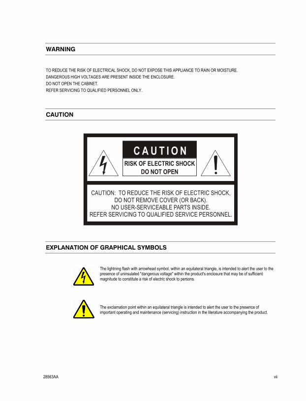
WARNING
TO REDUCE THE RISK OF ELECTRICAL SHOCK, DO NOT EXPOSE THIS APPLIANCE TO RAIN OR MOISTURE. DANGEROUS HIGH VOLTAGES ARE PRESENT INSIDE THE ENCLOSURE. DO NOT OPEN THE CABINET. REFER SERVICING TO QUALIFIED PERSONNEL ONLY.
CAUTION
CAUTION: TO REDUCE THE RISK OF ELECTRIC SHOCK, DO NOT REMOVE COVER (OR BACK).
NO USER-SERVICEABLE PARTS INSIDE.REFER SERVICING TO QUALIFIED SERVICE PERSONNEL.
C A U T I O NRISK OF ELECTRIC SHOCK
DO NOT OPEN
EXPLANATION OF GRAPHICAL SYMBOLS
The lightning flash with arrowhead symbol, within an equilateral triangle, is intended to alert the user to the presence of uninsulated "dangerous voltage" within the product's enclosure that may be of sufficient magnitude to constitute a risk of electric shock to persons.
The exclamation point within an equilateral triangle is intended to alert the user to the presence of important operating and maintenance (servicing) instruction in the literature accompanying the product.
viii 28563AA
Standard Warranty
Openeye warrants all products to be free from defects in workmanship and material under normal use for a period of one year after the date of purchase. Any defective product that falls under this warranty will, at OpenEye's discretion, be repaired or replaced at no additional charge. Openeye may elect to replace defective products with new or factory reconditioned products of equal or greater value. Repairs made necessary by reason of misuse, alteration, normal wear, or accident are not covered under this warranty. Exceptions to this are listed below: • Two years on all X-Series, XR Series, H Series, and HR Series Digital Recorders • Three years on all E-Series Digital Recorders • Two years on all Dome Cameras OpenEye will warrant all otherwise out of warranty replacement parts and repairs for 90 days from the date of OpenEye shipment. The above warranty is the sole warranty made by OpenEye and is in lieu of all other warranties by OpenEye express and implied, including without limitation the warranties of merchantability and fitness for a particular purpose. Under no circumstances will OpenEye be liable for any consequential, incidental, special or exemplary damages arising out of or connected with the sale, delivery, use or performance of the product, even if OpenEye is apprised of the likelihood of such damages occurring. In no event shall OpenEye liability exceed the purchase price of the product. This warranty gives you specific legal rights and you may also have other rights which vary from state to state or country to country.

28563AA ix

x 28563AA
NOTES:
28563AA xi
Table of Contents
INTRODUCTION ............................................................................................................ 1 PRODUCT DESCRIPTION ...................................................................................................................... 1 FEATURES .............................................................................................................................................. 1
CONTROLS AND CONNECTIONS ................................................................................ 3 FRONT PANEL ........................................................................................................................................ 3 REAR PANEL ........................................................................................................................................... 4
GETTING STARTED ...................................................................................................... 7 SYSTEM SETUP ...................................................................................................................................... 7
Connecting RS-485 Cables .................................................................................................................. 7 RJ-11 (6P6C) Connector Definition ...................................................................................................... 7 Turn On the Keyboard .......................................................................................................................... 7
Standby Mode Actions ..................................................................................................................... 8 KEYBOARD SYSTEM SETTING ............................................................................................................. 8
1.1 System Linking ............................................................................................................................... 8 1.2 Keyboard ID Assignment ............................................................................................................... 8 1.3 System Monitor .............................................................................................................................. 8 1.4 RS-232 Baud Rate Setting ............................................................................................................. 8 1.5 System Date Setting ....................................................................................................................... 9 1.6 System Time Setting ...................................................................................................................... 9 1.7 Date/Time Correction ..................................................................................................................... 9 1.8 System Alarm List .......................................................................................................................... 9 1.9 Camera Type and System Baud Rate Setting ............................................................................... 9
Assign Camera Type ....................................................................................................................... 9 Set the System Baud Rate ............................................................................................................ 10
1.10 Key Press Beep .......................................................................................................................... 10 1.11 Alarm Response ......................................................................................................................... 10 1.12 Password Setting ....................................................................................................................... 10 Lock Keys ........................................................................................................................................... 10
DOME CAMERA CONTROL .................................................................................................................. 11 Select a Camera ................................................................................................................................. 12 Accessing the Camera OSD Menu .................................................................................................... 12 Joystick ............................................................................................................................................... 12 Preset Function .................................................................................................................................. 12
Set Preset Position ........................................................................................................................ 12 Go to Preset Position ..................................................................................................................... 12
Tour Function ..................................................................................................................................... 13 Set Tour Line ................................................................................................................................. 13 Execute Tour Function ................................................................................................................... 13 Insert or Delete Point ..................................................................................................................... 13 Exiting Tour Mode .......................................................................................................................... 14
Auto Scan ........................................................................................................................................... 14 Setting an Auto Scan Line ............................................................................................................. 14 Executing the Auto Scan Line ........................................................................................................ 14
Pattern ................................................................................................................................................ 14 Setting the Pattern Path ................................................................................................................. 14 Executing the Pattern Path ............................................................................................................ 14
Camera Lens Control ......................................................................................................................... 15 Brightness Function ....................................................................................................................... 15 Focus Function .............................................................................................................................. 15
xii 28563AA
Zoom Function ............................................................................................................................... 15 Auto Focus Function ...................................................................................................................... 15
DVR CONTROL ...................................................................................................................................... 16 Connect the Control Keyboard to the DVR ......................................................................................... 17 Select a DVR ...................................................................................................................................... 17 Display Function ................................................................................................................................. 17 Search Function .................................................................................................................................. 17
NOTES:APPENDIX A: SPECIFICATIONS ................................................................... 18 APPENDIX A: SPECIFICATIONS ................................................................................ 19 APPENDIX B: FUNCTION TREE ................................................................................. 21
SYSTEM FUNCTION TREE ................................................................................................................... 21 DVR CONTROL MODE .......................................................................................................................... 21 DOME CAMERA CONTROL MODE ...................................................................................................... 22

28563AA xiii
NOTES:

xiv 28563AA
NOTES:
28563AA 1
INTRODUCTION
PRODUCT DESCRIPTION
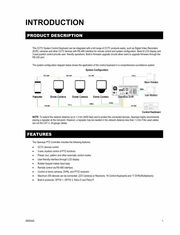
This CCTV System Control Keyboard can be integrated with a full range of CCTV products easily, such as Digital Video Recorders (DVR), cameras and other CCTV devices with RS-485 interface for remote control and system configuration. Back lit LCD display and 3-axis joystick control provide user- friendly operations. Built-in firmware upgrade circuits allow users to upgrade firmware through the RS-232 port. The system configuration diagram below shows the application of the control keyboard in a comprehensive surveillance system.
System Configuration
NOTE: To extend the network distance up to 1.2 km (4000 feet) and to protect the connected devices, Openeye highly recommends placing a repeater at the mid-point. However, a repeater may be needed in the network distance less than 1.2 km if the used cables are not the CAT 5, 24-gauge cables.
FEATURES
The Openeye PTZ Controller includes the following features:
• CCTV devices control • 3-axis Joystick control of PTZ functions • Preset, tour, pattern and other automatic control modes • User-friendly interface through LCD display • Rubber keypad makes input easy • Remote control via RS-485 interface. • Control of dome cameras, DVRs, and P/T/Z receivers • Maximum 255 devices can be connected. (223 Cameras or Receivers, 16 Control Keyboards and 17 DVRs/Multiplexers) • Built-in protocols: OPTIX 1, OPTIX 3, Pelco D and Pelco P

2 28563AA
NOTES:
28563AA 3
CONTROLS AND CONNECTIONS
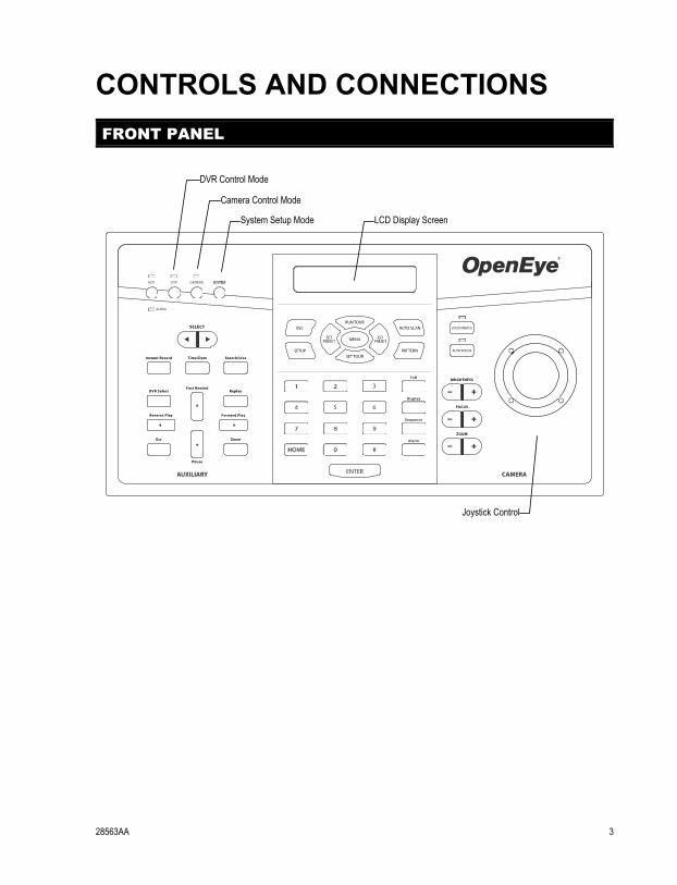
FRONT PANEL
SYSTEM
System Setup Mode
Camera Control Mode
DVR Control Mode
Joystick Control
LCD Display Screen
4 28563AA
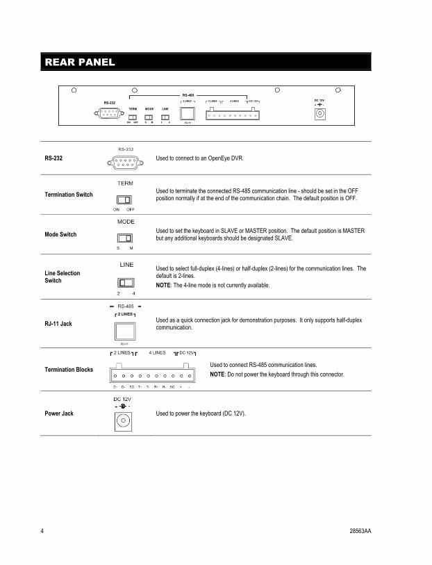
REAR PANEL
RS-232
Used to connect to an OpenEye DVR.
Termination Switch
Used to terminate the connected RS-485 communication line - should be set in the OFF position normally if at the end of the communication chain. The default position is OFF.
Mode Switch
Used to set the keyboard in SLAVE or MASTER position. The default position is MASTER but any additional keyboards should be designated SLAVE.
Line Selection Switch
Used to select full-duplex (4-lines) or half-duplex (2-lines) for the communication lines. The default is 2-lines. NOTE: The 4-line mode is not currently available.
RJ-11 Jack
Used as a quick connection jack for demonstration purposes. It only supports half-duplex communication.
Termination Blocks
Used to connect RS-485 communication lines. NOTE: Do not power the keyboard through this connector.
Power Jack
Used to power the keyboard (DC 12V).
RS-232
TERM MODE LINE
ON OFF S M 2 4 RJ-11
2 LINES
RS-485
+ -DC 12V2 LINES 4 LINES DC 12V

28563AA 5
NOTES:

6 28563AA
NOTES:
28563AA 7
GETTING STARTED
SYSTEM SETUP
The control keyboard can be connected with a speed dome camera or DVR. The following sections describe basic connections in a surveillance system.
CONNECTING RS-485 CABLES
To operate dome cameras, a control keyboard (or other control device, e.g. DVR) is needed to communicate all devices via RS-485 interface. The CAT 5 (Shielded twisted pairs) cables are recommended for RS-485 communication; maximum cable length for over 24-gauge wire is 4000 feet (1219 meters). If the total cable length is over 4000 feet, using a repeater to enlarge the signals is recommended. Terminal block is designed for long distance installation. Users can construct a RS-485 network through the terminal block located on the rear panel of the control keyboard. Detailed pin definition can be found on the terminal block.
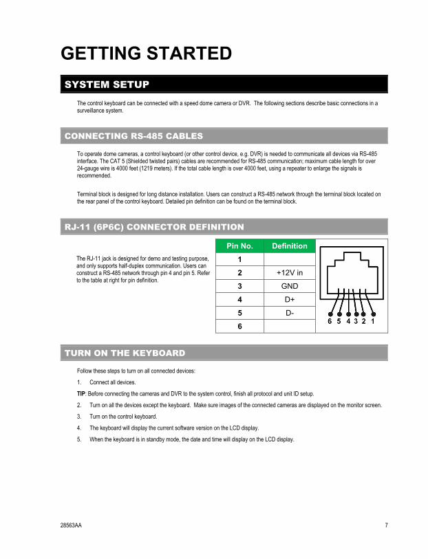
RJ-11 (6P6C) CONNECTOR DEFINITION
Pin No. Definition
The RJ-11 jack is designed for demo and testing purpose, and only supports half-duplex communication. Users can construct a RS-485 network through pin 4 and pin 5. Refer to the table at right for pin definition.
1
2 +12V in
3 GND
4 D+
5 D-
6
TURN ON THE KEYBOARD
Follow these steps to turn on all connected devices:
1. Connect all devices.
TIP: Before connecting the cameras and DVR to the system control, finish all protocol and unit ID setup.
2. Turn on all the devices except the keyboard. Make sure images of the connected cameras are displayed on the monitor screen.
3. Turn on the control keyboard.
4. The keyboard will display the current software version on the LCD display.
5. When the keyboard is in standby mode, the date and time will display on the LCD display.
8 28563AA
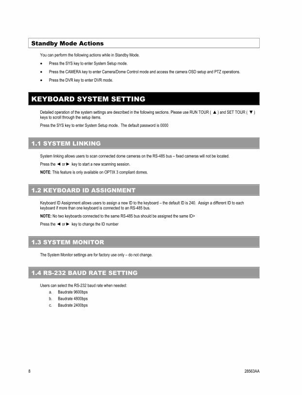
Standby Mode Actions
You can perform the following actions while in Standby Mode.
• Press the SYS key to enter System Setup mode.
• Press the CAMERA key to enter Camera/Dome Control mode and access the camera OSD setup and PTZ operations.
• Press the DVR key to enter DVR mode.
KEYBOARD SYSTEM SETTING
Detailed operation of the system settings are described in the following sections. Please use RUN TOUR ( �) and SET TOUR ( �) keys to scroll through the setup items.
Press the SYS key to enter System Setup mode. The default password is 0000
1.1 SYSTEM LINKING
System linking allows users to scan connected dome cameras on the RS-485 bus – fixed cameras will not be located.
Press the � or � key to start a new scanning session.
NOTE: This feature is only available on OPTIX 3 compliant domes.
1.2 KEYBOARD ID ASSIGNMENT
Keyboard ID Assignment allows users to assign a new ID to the keyboard – the default ID is 240. Assign a different ID to each keyboard if more than one keyboard is connected to an RS-485 bus.
NOTE: No two keyboards connected to the same RS-485 bus should be assigned the same ID>
Press the � or � key to change the ID number
1.3 SYSTEM MONITOR
The System Monitor settings are for factory use only – do not change.
1.4 RS-232 BAUD RATE SETTING
Users can select the RS-232 baud rate when needed: a. Baudrate 9600bps b. Baudrate 4800bps c. Baudrate 2400bps
28563AA 9
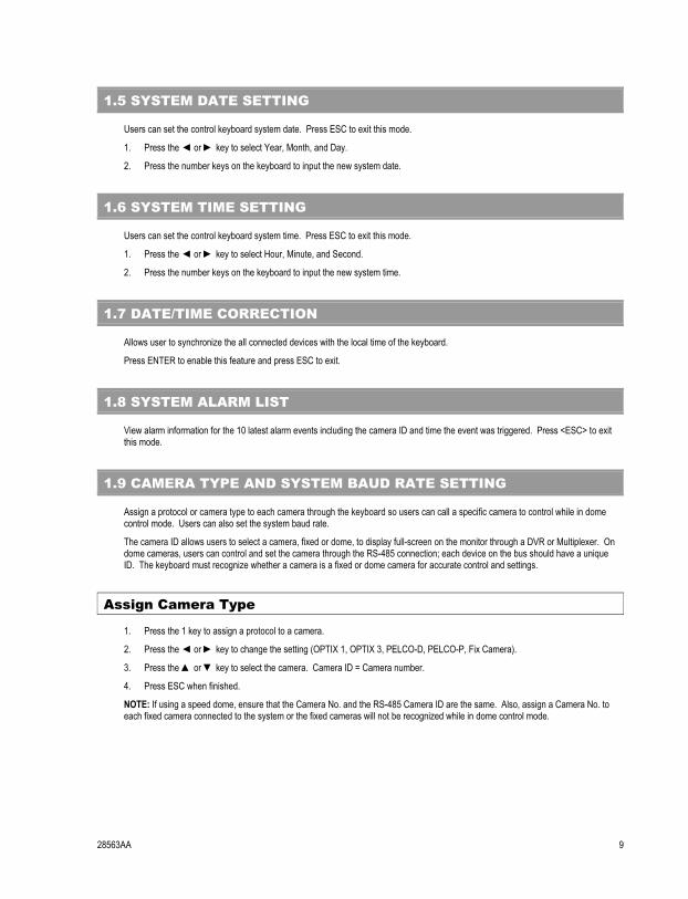
1.5 SYSTEM DATE SETTING
Users can set the control keyboard system date. Press ESC to exit this mode.
1. Press the � or � key to select Year, Month, and Day.
2. Press the number keys on the keyboard to input the new system date.
1.6 SYSTEM TIME SETTING
Users can set the control keyboard system time. Press ESC to exit this mode.
1. Press the � or � key to select Hour, Minute, and Second.
2. Press the number keys on the keyboard to input the new system time.
1.7 DATE/TIME CORRECTION
Allows user to synchronize the all connected devices with the local time of the keyboard.
Press ENTER to enable this feature and press ESC to exit.
1.8 SYSTEM ALARM LIST
View alarm information for the 10 latest alarm events including the camera ID and time the event was triggered. Press <ESC> to exit this mode.
1.9 CAMERA TYPE AND SYSTEM BAUD RATE SETTING
Assign a protocol or camera type to each camera through the keyboard so users can call a specific camera to control while in dome control mode. Users can also set the system baud rate.
The camera ID allows users to select a camera, fixed or dome, to display full-screen on the monitor through a DVR or Multiplexer. On dome cameras, users can control and set the camera through the RS-485 connection; each device on the bus should have a unique ID. The keyboard must recognize whether a camera is a fixed or dome camera for accurate control and settings.
Assign Camera Type
1. Press the 1 key to assign a protocol to a camera.
2. Press the � or � key to change the setting (OPTIX 1, OPTIX 3, PELCO-D, PELCO-P, Fix Camera).
3. Press the � or � key to select the camera. Camera ID = Camera number.
4. Press ESC when finished.
NOTE: If using a speed dome, ensure that the Camera No. and the RS-485 Camera ID are the same. Also, assign a Camera No. to each fixed camera connected to the system or the fixed cameras will not be recognized while in dome control mode.
10 28563AA
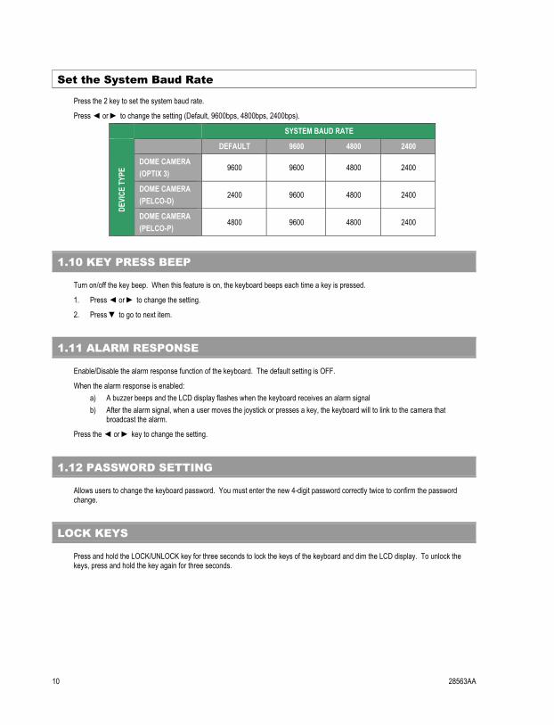
Set the System Baud Rate
Press the 2 key to set the system baud rate.
Press � or � to change the setting (Default, 9600bps, 4800bps, 2400bps).
SYSTEM BAUD RATE DE
VICE
TYP
E
DEFAULT 9600 4800 2400
DOME CAMERA (OPTIX 3)
9600 9600 4800 2400
DOME CAMERA (PELCO-D)
2400 9600 4800 2400
DOME CAMERA (PELCO-P)
4800 9600 4800 2400
1.10 KEY PRESS BEEP
Turn on/off the key beep. When this feature is on, the keyboard beeps each time a key is pressed.
1. Press � or � to change the setting.
2. Press � to go to next item.
1.11 ALARM RESPONSE
Enable/Disable the alarm response function of the keyboard. The default setting is OFF.
When the alarm response is enabled: a) A buzzer beeps and the LCD display flashes when the keyboard receives an alarm signal b) After the alarm signal, when a user moves the joystick or presses a key, the keyboard will to link to the camera that
broadcast the alarm.
Press the � or � key to change the setting.
1.12 PASSWORD SETTING
Allows users to change the keyboard password. You must enter the new 4-digit password correctly twice to confirm the password change.
LOCK KEYS
Press and hold the LOCK/UNLOCK key for three seconds to lock the keys of the keyboard and dim the LCD display. To unlock the keys, press and hold the key again for three seconds.
28563AA 11
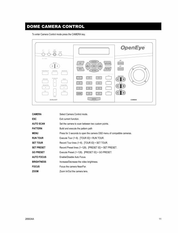
DOME CAMERA CONTROL
To enter Camera Control mode press the CAMERA key.
CAMERA Select Camera Control mode.
ESC Exit current function.
AUTO SCAN Set the camera to scan between two custom points.
PATTERN Build and execute the pattern path
MENU Press for 3 seconds to open the camera OSD menu of compatible cameras.
RUN TOUR Execute Tour (1~8). [TOUR ID] + RUN TOUR.
SET TOUR Record Tour lines (1~8). [TOUR ID] + SET TOUR.
SET PRESET Record Preset lines (1~128). [PRESET ID] + SET PRESET.
GO PRESET Execute Preset (1~128). [PRESET ID] + GO PRESET.
AUTO FOCUS Enable/Disable Auto Focus.
BRIGHTNESS Increase/Decrease the video brightness.
FOCUS Focus the camera Near/Far.
ZOOM Zoom In/Out the camera lens.
SYSTEM
12 28563AA
SELECT A CAMERA
Select a camera to control with the keyboard control joystick:
1. Press the camera ID number of the dome camera.
2. Press ENTER to confirm.
You can now control the camera with the joystick.
ACCESSING THE CAMERA OSD MENU
To open the OSD menu of the selected camera:
Press and hold the MENU key for three seconds. To exit the camera menu, press and hold the MENU key.
NOTE: In the dome camera’s OSD, the MENU key functions as Enter and Exit.
NOTE: This feature is only available on cameras that are equipped with the OSD function. For further details about the OSD setup on a camera, refer to documentation provided by the manufacturer.
TIP: On cameras using the Pelco protocol, the joystick can be used to navigate the camera OSD.
JOYSTICK
Use the joystick to Pan/Tilt/Zoom cameras.
TIP: On cameras using the Pelco protocol, the joystick can be used to navigate the camera OSD.
PRESET FUNCTION
In Camera Control mode, you can operate the preset function. Follow the instructions below to set and run preset positions. Up to 128 preset positions can be set through the keyboard.
Set Preset Position
1. Use the joystick to locate the desired camera position.
2. Press a number key to assign a preset number.
3. Press SET PRESET to record the preset position.
Go to Preset Position
1. Press a number key to call the desired preset position
2. Press GO PRESET to go to the preset position.
28563AA 13
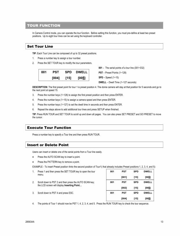
TOUR FUNCTION
In Camera Control mode, you can operate the tour function. Before setting this function, you must pre-define at least two preset positions. Up to eight tour lines can be set using the keyboard controller.
Set Tour Line
TIP: Each Tour Line can be composed of up to 32 preset positions.
1. Press a number key to assign a tour number.
2. Press the SET TOUR key to modify the tour parameters.
001 PST SPD DWELL
[004] [15] [005]
001 – The serial points of a tour line (001~032)
PST – Preset Points (1~128)
SPD – Speed (1~15)
DWELL – Dwell Time (1~127 seconds)
DESCRIPTION: The first preset point for tour 1 is preset position 4. The dome camera will stay at that position for 5 seconds and go to the next point at speed 15.
3. Press the number keys (1~128) to assign the first preset position and then press ENTER.
4. Press the number keys (1~15) to assign a camera speed and then press ENTER.
5. Press the number keys (1~127) to set the dwell time in seconds and then press ENTER.
6. Repeat the steps above to add additional tour lines and press SETUP when finished.
TIP: Press RUN TOUR and SET TOUR to scroll up and down all pages. You can also press SET PRESET and GO PRESET to move the cursor.
Execute Tour Function
Press a number key to specify a Tour line and then press RUN TOUR.
Insert or Delete Point
Users can insert or delete one of the serial points from a Tour line easily.
• Press the AUTO SCAN key to insert a point.
• Press the PATTERN key to remove a point.
EXAMPLE - To insert Preset position 4into the second position of Tour1( that already includes Preset positions 1, 2, 3, 4, and 5):
1. Press 1 and then press the SET TOUR key to open the tour menu.
001 PST SPD DWELL
[001] [15] [005]
2. Scroll down to PST 2 and then press the AUTO SCAN key; the LCD screen will display Inserting Point…
001 PST SPD DWELL
[002] [15] [005]
3. Scroll down to PST 4 and press ESC. 001 PST SPD DWELL
[004] [15] [005]
4. The points of Tour 1 should now be PST 1, 4, 2, 3, 4, and 5. Press the RUN TOUR key to check the tour sequence.
14 28563AA
Exiting Tour Mode
Press the ESC key to exit the Tour mode after configuring a tour line.
AUTO SCAN
You can control the Auto Scan function of a dome camera under the Camera Control mode; one auto scan line can be set using the keyboard.
Setting an Auto Scan Line
1. Press the AUTO SCAN key to enter Auto Scan mode. The LCD screen will display 1.RUN 2.SETTING.
2. Press 2 to configure the Auto Scan parameters.
3. Move the dome camera to the desired position and press ENTER to save it as the start position.
4. Pan the camera to the next position and press ENTER to save it as the end position.
5. Select the scan direction (RIGHT/LEFT) using the direction keys and then press ENTER.
6. Select the speed (1-4) using the direction keys and then press ENTER.
Executing the Auto Scan Line
1. Press the AUTO SCAN key to enter Auto Scan mode. The LCD screen will display 1.RUN 2.SETTING.
2. Press 1 to run the Auto Scan function.
3. Press ESC to exit the auto scan mode.
PATTERN
Setting the Pattern Path
1. Press PATTERN to enter the Pattern mode. The LCD screen will display 1.RUN 2.SETTING.
2. Press 2 to configure the Pattern path.
3. When the LCD screen displays ENTER for Start Pos. press ENTER and use the joystick to rotate the camera and form a pattern path.
4. Press ENTER to set the Pattern end position.
5. When the LCD screen displays ENTER for Saving press ENTER to save the pattern path.
Executing the Pattern Path
1. Press PATTERN to enter the Pattern mode. The LCD screen will display 1.RUN 2.SETTING.
2. Press 1 to run the Pattern path.
3. Press ESC to exit the Pattern mode.
28563AA 15
CAMERA LENS CONTROL
You can control the functions of a camera lens while in Camera Control mode.
Brightness Function
• Press the BRIGHTNESS + key to increase the video brightness.
• Press the BRIGHTNESS - key to decrease the video brightness.
Focus Function
• Press the FOCUS NEAR key to move the lens’ focus near.
• Press the FOCUS FAR key to move the lens’ focus far.
NOTE: AUTO FOCUS will turn off when you use the FOCUS NEAR and FOCUS FAR keys.
Zoom Function
• Press the ZOOM TELE key to zoom in the lens.
• Press the ZOOM WIDE key to zoom out the lens.
Auto Focus Function
• Press AUTO FOCUS to toggle the Auto Focus function. The LED is lit when the function is on.
NOTE: When you manually operate the focus functions of the camera with the FOCUS NEAR and FOCUS FAR keys the Auto Focus function, and the LED light, will turn off automatically.
16 28563AA
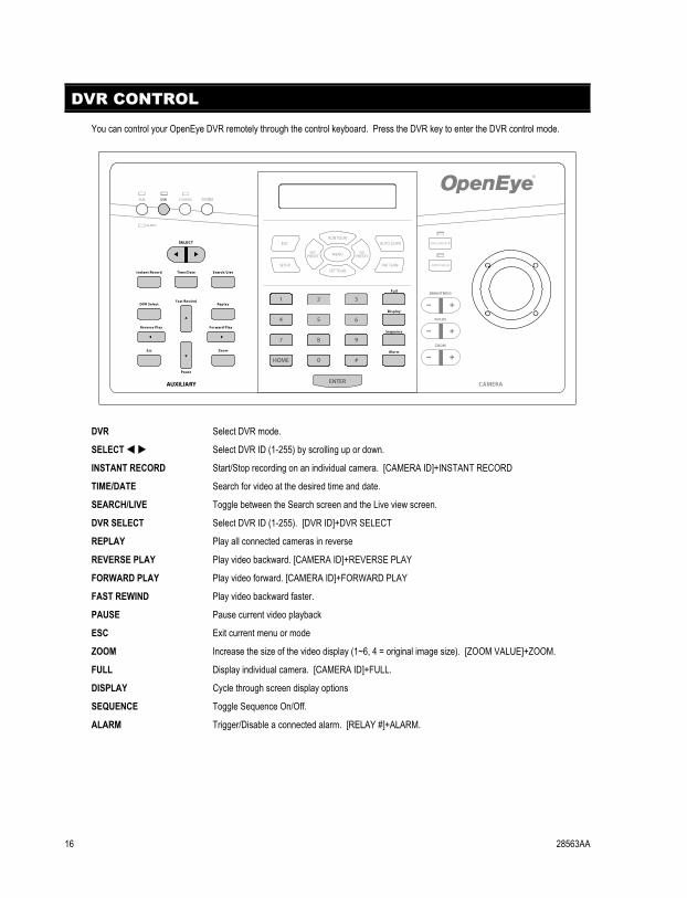
DVR CONTROL
You can control your OpenEye DVR remotely through the control keyboard. Press the DVR key to enter the DVR control mode.
DVR Select DVR mode.
SELECT�� Select DVR ID (1-255) by scrolling up or down.
INSTANT RECORD Start/Stop recording on an individual camera. [CAMERA ID]+INSTANT RECORD
TIME/DATE Search for video at the desired time and date.
SEARCH/LIVE Toggle between the Search screen and the Live view screen.
DVR SELECT Select DVR ID (1-255). [DVR ID]+DVR SELECT
REPLAY Play all connected cameras in reverse
REVERSE PLAY Play video backward. [CAMERA ID]+REVERSE PLAY
FORWARD PLAY Play video forward. [CAMERA ID]+FORWARD PLAY
FAST REWIND Play video backward faster.
PAUSE Pause current video playback
ESC Exit current menu or mode
ZOOM Increase the size of the video display (1~6, 4 = original image size). [ZOOM VALUE]+ZOOM.
FULL Display individual camera. [CAMERA ID]+FULL.
DISPLAY Cycle through screen display options
SEQUENCE Toggle Sequence On/Off.
ALARM Trigger/Disable a connected alarm. [RELAY #]+ALARM.
SYSTEM
28563AA 17
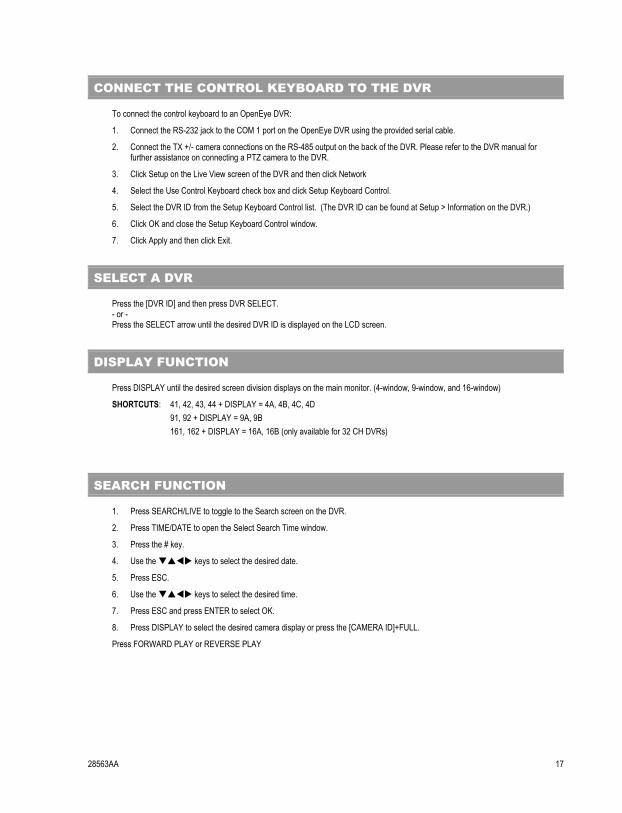
CONNECT THE CONTROL KEYBOARD TO THE DVR
To connect the control keyboard to an OpenEye DVR:
1. Connect the RS-232 jack to the COM 1 port on the OpenEye DVR using the provided serial cable.
2. Connect the TX +/- camera connections on the RS-485 output on the back of the DVR. Please refer to the DVR manual for further assistance on connecting a PTZ camera to the DVR.
3. Click Setup on the Live View screen of the DVR and then click Network
4. Select the Use Control Keyboard check box and click Setup Keyboard Control.
5. Select the DVR ID from the Setup Keyboard Control list. (The DVR ID can be found at Setup > Information on the DVR.)
6. Click OK and close the Setup Keyboard Control window.
7. Click Apply and then click Exit.
SELECT A DVR
Press the [DVR ID] and then press DVR SELECT. - or - Press the SELECT arrow until the desired DVR ID is displayed on the LCD screen.
DISPLAY FUNCTION
Press DISPLAY until the desired screen division displays on the main monitor. (4-window, 9-window, and 16-window)
SHORTCUTS: 41, 42, 43, 44 + DISPLAY = 4A, 4B, 4C, 4D 91, 92 + DISPLAY = 9A, 9B 161, 162 + DISPLAY = 16A, 16B (only available for 32 CH DVRs)
SEARCH FUNCTION
1. Press SEARCH/LIVE to toggle to the Search screen on the DVR.
2. Press TIME/DATE to open the Select Search Time window.
3. Press the # key.
4. Use the ���� keys to select the desired date.
5. Press ESC.
6. Use the ���� keys to select the desired time.
7. Press ESC and press ENTER to select OK.
8. Press DISPLAY to select the desired camera display or press the [CAMERA ID]+FULL.
Press FORWARD PLAY or REVERSE PLAY

18 28563AA
NOTES:
28563AA 19
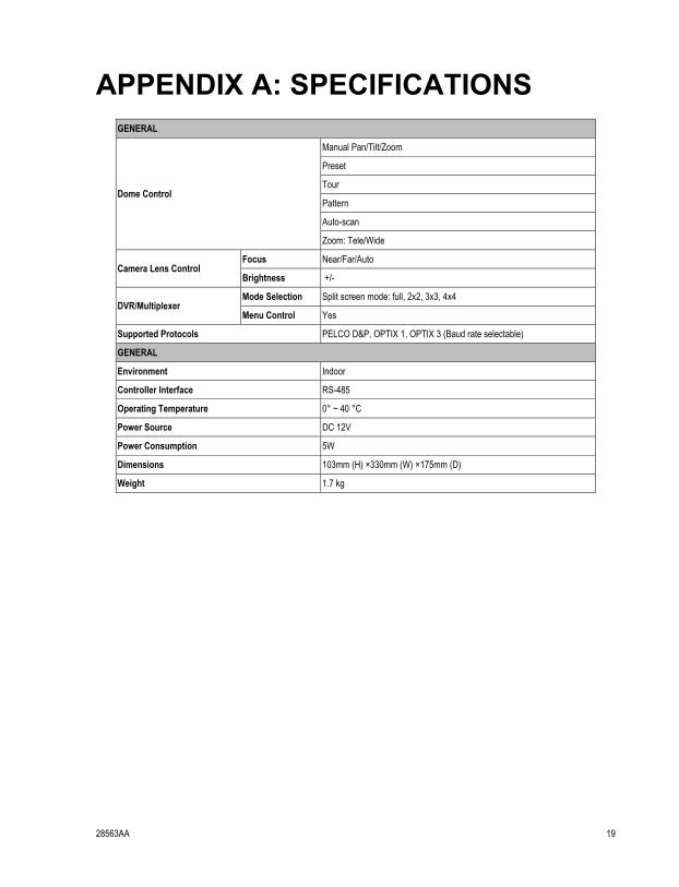
APPENDIX A: SPECIFICATIONS
GENERAL
Dome Control
Manual Pan/Tilt/Zoom
Preset
Tour
Pattern
Auto-scan
Zoom: Tele/Wide
Camera Lens Control Focus Near/Far/Auto
Brightness +/-
DVR/Multiplexer Mode Selection Split screen mode: full, 2x2, 3x3, 4x4
Menu Control Yes
Supported Protocols PELCO D&P, OPTIX 1, OPTIX 3 (Baud rate selectable)
GENERAL
Environment Indoor
Controller Interface RS-485
Operating Temperature 0° ~ 40 °C
Power Source DC 12V
Power Consumption 5W
Dimensions 103mm (H) ×330mm (W) ×175mm (D)
Weight 1.7 kg

20 28563AA
NOTES:
28563AA 21
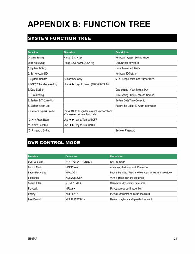
APPENDIX B: FUNCTION TREE
SYSTEM FUNCTION TREE
Function Operation Description
System Setting Press <SYS> key Keyboard System Setting Mode
Lock the keypad Press <LOCK/UNLOCK> key Lock/Unlock keyboard
1. System Linking Scan the existed device
2. Set Keyboard ID Keyboard ID Setting
3. System Monitor Factory Use Only MPX, Supper MMX and Supper MPX
4. RS-232 Baud-rate setting Use � � keys to Select (2400/4800/9600)
5. Date Setting Date setting : Year, Month, Day
6. Time Setting Time setting : Hours, Minute, Second
7. System D/T Correction System Date/Time Correction
8. System Alarm List Record the Latest 10 Alarm Information
9. Camera Type & Speed Press <1> to assign the camera’s protocol and <2> to select system baud rate
10. Key Press Beep Use � � key to Turn ON/OFF
11. Alarm Reaction Use � � key to Turn ON/OFF
12. Password Setting Set New Password
DVR CONTROL MODE
Function Operation Description
DVR Selection <1> ~ <255> + <ENTER> DVR selection
Screen Mode <DISPLAY> 4-window, 9-window and 16-window
Pause Recording <PAUSE> Pause live video; Press the key again to return to live video
Sequence <SEQUENCE> View a preset camera sequence
Search Files <TIME/DATE> Search files by specific date, time.
Playback <PLAY> Playback recorded image files
Replay <REPLAY> Play all connected cameras backward
Fast Rewind <FAST REWIND> Rewind playback and speed adjustment
22 28563AA
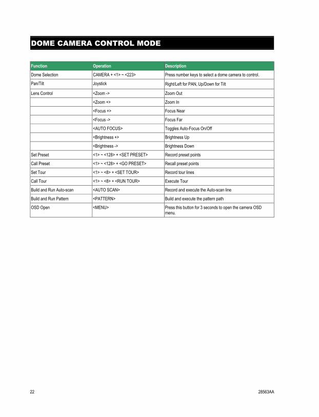
DOME CAMERA CONTROL MODE
Function Operation Description
Dome Selection CAMERA + <1> ~ <223> Press number keys to select a dome camera to control.
Pan/Tilt Joystick Right/Left for PAN, Up/Down for Tilt
Lens Control <Zoom -> Zoom Out
<Zoom +> Zoom In
<Focus +> Focus Near
<Focus -> Focus Far
<AUTO FOCUS> Toggles Auto-Focus On/Off
<Brightness +> Brightness Up
<Brightness -> Brightness Down
Set Preset <1> ~ <128> + <SET PRESET> Record preset points
Call Preset <1> ~ <128> + <GO PRESET> Recall preset points
Set Tour <1> ~ <8> + <SET TOUR> Record tour lines
Call Tour <1> ~ <8> + <RUN TOUR> Execute Tour
Build and Run Auto-scan <AUTO SCAN> Record and execute the Auto-scan line
Build and Run Pattern <PATTERN> Build and execute the pattern path
OSD Open <MENU> Press this button for 3 seconds to open the camera OSD menu.

28563AA 23
NOTES:
24 28563AA
www.openeye.net 1-888-542-1103
© 2008 Openeye Inc. All rights reserved. No part of this publication may be reproduced by any means without written permission from Openeye Inc. The information in this publication is believed to be accurate in all respects. However, Openeye cannot assume responsibility for any consequences resulting from the use thereof. The information contained herein is subject to change without notice. Revisions or new editions to this publication may be issued to incorporate such changes.