Embed Size (px)
Citation preview

Template-based Service ProvisioningConcepts and Processes Guide
5.1


Template-Based Service ProvisioningConcepts and Processes Guide
FIRST EDITION
MetaSolv Solution™ M/5.1

Copyright and Trademark Information
MetaSolv Software, the MetaSolv logo, MetaSolv Solution, Framework for Success, MetaSolv QuickStart, MetaSolv eService, MetaSolv Field Operations Portal, Rapid Results, and MetaSolv Network and Service Planning are trademarks of MetaSolv Software, Inc. MetaSolv is a trademark registered in the United States of America by MetaSolv Software, Inc.COMMON LANGUAGE is a registered trademark, and Telcordia, CLCI, CLEI, CLFI, and CLLI are trademarks of Telcordia Technologies, Inc. (formerly Bellcore).Cygent is a trademark of Cygent, Inc.HipLink is a trademark of Cross Communications, Inc.InfoMaker and PowerBuilder are registered trademarks of Sybase, Inc.Microsoft, Windows, Windows 95, Windows 98, Windows 2000, and Windows NT are registered trademarks of Microsoft Corporation.Oracle is a registered trademark of Oracle Corporation.Saville CBP is a registered trademark of Saville Systems.SilverStream, SilverJServer, SilverJRunner, JRunner, JBroker, SilverMonitor, and SilverJunction are trademarks of SilverStream Software, Inc.Sun, Sun Microsystems, the Sun logo, Java, and all Java-based marks are trademarks or registered trademarks of Sun Microsystems, Inc. in the United States and other countries.All other marks are the property of their respective owners.Copyright © 1994 - 2001 MetaSolv Software, Inc. All rights reserved.
DisclaimerAll references to future incorporation of new or enhanced product functionality, or to future release dates, are estimates only, and MetaSolv may change them at any time, without notice. Information in this document is subject to change without notice and does not represent a commitment on the part of MetaSolv Software, Inc. All references to new or enhanced product functionality, or to future release dates, are estimates only, and MetaSolv may change them at any time, without notice.The software and/or databases described in this document are furnished under a written license agreement or nondisclosure agreement. No part of this document, the software and/or databases may be used, reproduced or transmitted in any form or by any means, electronic or mechanical, including copying, photocopying, recording, or information storage or retrieval systems, for any purpose without the written permission of MetaSolv Software, Inc., except as specifically allowed in the written license or nondisclosure agreement. It is against the law to copy the software on any medium except as specifically allowed in the license or nondisclosure agreement.MetaSolv Software, Inc. assumes no responsibility or liability for any errors or inaccuracies that may appear in this manual.
Use of any of this Software’s functionality in a manner inconsistent with your license grant, whether or not protected by the Product ID, is a breach of the license agreement between your company and MetaSolv. A listing of the software options for which you possess a license may be viewed by navigating to Options>Software Options.This Software contains sample network system templates (“Templates”). MetaSolv does not provide, and is not obligated to provide, Standard Maintenance and Support for the Templates or any modifications made thereto. The Templates are delivered as is and without warranty of any kind.
Printed in U.S.A.MetaSolv Software, Inc.5560 Tennyson ParkwayPlano, TX 75024 U.S.A

CONTINUOUS PUBLICATIONHow It Works for You
This document is one of multiple published editions of this Concepts and Processes Guide. There are sections in this edition that are still in development. Those sections are identified by a descriptive heading and the following symbol and note:
Under Development
The next edition of the CAP guide will replace that note with the information described in the heading. You will know that the next edition has been published when you see it announced in the ReadMe accompanying a service pack, and when you read about it on the MetaSolv web site (www.metasolv.com). As soon as a subsequent edition is published, you can access it from the Download area of your customer or partner portal on the Web site.
We are pleased to be able to provide you with the most up-to-date and accurate documentation possible through this approach to publication. As always, we appreciate all of your suggestions and comments on ways we can improve our documentation. Please send comments to: [email protected]


Template-Based Service Provisioning Concepts and Processes GuideMetaSolv Solution™ M/5.1
Contents
About This GuidePurpose .............................................................................................................................................................................xiAudience ...........................................................................................................................................................................xiBefore you begin ...........................................................................................................................................................xiHow this document is organized .............................................................................................................................xiiRelated documentation ..............................................................................................................................................xii
ConceptsWhat is service provisioning in M/5.1? ....................................................................................................................1
Features and functionality .................................................................................................................................1Provisioning .....................................................................................................................................................1Connection identification ...........................................................................................................................2Connection design .........................................................................................................................................2Service activation...........................................................................................................................................2Connection queries........................................................................................................................................3
End-to-end service delivery workflow ............................................................................................................3Integration with other subsystems and modules ........................................................................................3
Network management..................................................................................................................................3Order management .......................................................................................................................................4Work management ........................................................................................................................................4Trouble management....................................................................................................................................4
Processes Tasks and work queues .................................................................................................................................................5
Features and functionality .................................................................................................................................5Processes ...................................................................................................................................................................6
System/exception queue set up.................................................................................................................6Enhancing CKTID task functionality ........................................................................................................8Managing system and exception work queues ....................................................................................9
Service Request Connections window ......................................................................................................... 10Connection identification ......................................................................................................................................... 12
Features and functionality .............................................................................................................................. 13Default connection ID format................................................................................................................. 13Connection ID methods ............................................................................................................................ 13
Connection ID window ..................................................................................................................................... 14Procedures ............................................................................................................................................................ 15
Creating a connection ID with the manual ID method .................................................................. 15Creating a connection ID with the auto ID method........................................................................ 16Modifying a connection ID ...................................................................................................................... 18
Physical connection design ...................................................................................................................................... 19Features and functionality .............................................................................................................................. 19
Design methods ........................................................................................................................................... 19Supported capabilities............................................................................................................................... 19Network extensions.................................................................................................................................... 19Connection design tasks ........................................................................................................................... 20
Related windows ................................................................................................................................................. 20
1994-2001 MetaSolv Software, Inc. v
MetaSolv confidential. All rights reserved. Information subject to change without notice.

Concepts and Processes Guide Template-Based Service ProvisioningMetaSolv Solution™ M/5.1
Physical Connection Design window .................................................................................................... 20Network System/Element Query window............................................................................................ 23
Procedures ............................................................................................................................................................ 25Designing customer connections ........................................................................................................... 25Designing connections as part of a system ........................................................................................ 25
Bandwidth Allocation Report for connections ......................................................................................... 26Virtual connection design ......................................................................................................................................... 28
Process overview ................................................................................................................................................. 28Features and functionality .............................................................................................................................. 28
Design methods ........................................................................................................................................... 28Provisioning Dialog .................................................................................................................................... 29
Related windows ................................................................................................................................................. 29GLR................................................................................................................................................................... 29Properties window for elements ............................................................................................................ 33Viewing properties for connections ...................................................................................................... 34Custom Attributes window...................................................................................................................... 35
Procedures ............................................................................................................................................................ 36Designing a virtual connection in the GLR window ........................................................................ 36Modifying the design mode in the GLR window .............................................................................. 38Manually designing a virtual connection............................................................................................ 39Using path analysis to design a virtual connection......................................................................... 41Assigning IP addresses ............................................................................................................................... 42Making port assignments to a virtual connection ........................................................................... 42Allocating bandwidth to a virtual connection .................................................................................. 43Exporting a graphic canvas drawing .................................................................................................... 43Redesigning a virtual connection .......................................................................................................... 43Modifying design contact information................................................................................................ 44
Reports ................................................................................................................................................................... 45Port VC Limit Report .................................................................................................................................. 45GLR................................................................................................................................................................... 46
Service Activation ....................................................................................................................................................... 47Features and functionality .............................................................................................................................. 47
Ordered connections.................................................................................................................................. 47Non-ordered connections ........................................................................................................................ 47
Procedures ............................................................................................................................................................ 47Activating non-ordered connections and viewing gateway events ........................................... 47
Activation report ................................................................................................................................................ 47Connection queries ..................................................................................................................................................... 51
Related windows ................................................................................................................................................. 51Connection Design Query window ........................................................................................................ 51Connection Hierarchy Query window .................................................................................................. 52
Procedures ............................................................................................................................................................ 53Viewing existing circuit/connection designs...................................................................................... 53
Scenarios
SetupEnabling M/5.1 ............................................................................................................................................................. 57
Accessing software options ............................................................................................................................. 57
vi 1994-2001 MetaSolv Software, Inc.Information subject to change without notice. MetaSolv confidential. All rights reserved.

Template-Based Service Provisioning Concepts and Processes GuideMetaSolv Solution™ M/5.1
Product ID ............................................................................................................................................................. 57Software options ................................................................................................................................................ 57
Network management information and product offerings ........................................................................... 58Network templates ............................................................................................................................................. 58Custom attributes ............................................................................................................................................... 58Network designs .................................................................................................................................................. 58Product specs/catalog ....................................................................................................................................... 59Provisioning plans .............................................................................................................................................. 59
Setting related preferences ...................................................................................................................................... 59Use Default Connection ID Format preference ......................................................................................... 59Design Mode preference .................................................................................................................................. 60Maximum Number of Hops preference ....................................................................................................... 60
Configuration considerations .................................................................................................................................. 60Conversion and migration considerations ........................................................................................................... 60
1994-2001 MetaSolv Software, Inc. vii
MetaSolv confidential. All rights reserved. Information subject to change without notice.

Concepts and Processes Guide Template-Based Service ProvisioningMetaSolv Solution™ M/5.1
viii 1994-2001 MetaSolv Software, Inc.Information subject to change without notice. MetaSolv confidential. All rights reserved.

Template-Based Service Provisioning Concepts and Processes GuideMetaSolv Solution™ M/5.1
1994-2001 MetaSolv Software, Inc. ix
MetaSolv confidential. All rights reserved. Information subject to change without notice.
Figures
Figure 1: M/5.1’s end-to-end service delivery process ............................................................................................ 3Figure 2: Task Type window for the CKTID task ......................................................................................................... 8Figure 3: Provisioning Plan window .............................................................................................................................. 9Figure 4: Server Log List window .................................................................................................................................10Figure 5: Service Request Connections window from the CKTID task .............................................................11Figure 6: Service Request Connections window from the DLRD/RID task ......................................................12Figure 7: Managing a Connection Spec window in Network Templates .........................................................17Figure 8: Physical Connection Design window ........................................................................................................21Figure 9: Physical Connection Design window - Custom Attributes tab ........................................................22Figure 10: Physical Connection Design window - Network tab .........................................................................23Figure 11: Network System/Element Query window .............................................................................................24Figure 12: GLR window - Provisioning Dialog panel .............................................................................................30Figure 13: GLR window toolbar ....................................................................................................................................33Figure 14: View an Element window ..........................................................................................................................33Figure 15: Custom Attributes step in the GLR window ........................................................................................35Figure 16: GLR window - Design Options panel ......................................................................................................38Figure 17: GLR window - Available Connections panel ........................................................................................40Figure 18: GLR window - Administrative Section panel .......................................................................................44Figure 19: Activation Report .........................................................................................................................................48Figure 20: Connection Design Query window .........................................................................................................51Figure 21: Connection Hierarchy Query window ....................................................................................................52

Concepts and Processes Guide Template-Based Service ProvisioningMetaSolv Solution™ M/5.1
x 1994-2001 MetaSolv Software, Inc.Information subject to change without notice. MetaSolv confidential. All rights reserved.

About This Guide
PurposeThis guide provides detailed information that will help you provision any template-based connections your company offers. You should read this book if you want to familiarize yourself with the features, functions, and processes before you actually provision a connection or if you want some background on the new template-based functionality.
The information presented includes:
An overview of template-based functionality in general, so you can see how provisioning fits into the big picture
An explanation of how service provisioning works
A representation and description of the provisioning windows
Steps in the process of provisioning a new template-based connection
Scenarios for provisioning a VPN system and xDSL service
AudienceThis guide is intended for MetaSolv consultants, partners, and customers who provision template-based connections based on orders through PSR. In addition to those involved in implementing and supporting service provisioning, this book is useful to those who want to understand the implications of the M/5.1 templates functionality on provisioning.
Before you beginBefore you can provision connections for template-based products such as customer VPNs and customer connections, certain things must be made ready, such as:
❏ The MetaSolv Solution M/5.1 is installed.
❏ The PSR and network migration described in the MetaSolv Migration Guide is complete.
❏ Product specifications and product catalog include template-based products.
❏ Internal networks are fully designed on the network design canvas.
❏ Templates and custom attributes have been customized appropriately.
❏ Provisioning plans for template-based orders are available.
1994-2001 MetaSolv Software, Inc. xi
MetaSolv confidential. All rights reserved. Information subject to change without notice.

Concepts and Processes Guide Template-Based Service ProvisioningAbout This Guide MetaSolv Solution™ M/5.1
How this document is organizedThis book is organized into five chapters. Use the following table to identify the chapter that focuses on the information you need.
Related documentationThe following is a list of additional resources that provide specific information relative to the service provisioning functionality:
Concepts and Processes (CAP) guides
The following documents are available through the customer and partner portals on the MetaSolv Web site:
Network Templates Concepts and Processes Guide
Template-based Network Designs Concepts and Processes Guide
Template-based Product Specifications Concepts and Processes Guide
Template-based Ordering Concepts and Processes Guide
Technology modules documents
The following documents are available, with the purchase of the related technology module, through the customer and partner portals on the MetaSolv Web site:
ATM/Frame Relay Technology Module
DLC Technology Module
DSL Technology Module
Ethernet Technology Module
IP Technology Module
MPLS Technology Module
To learn about... see chapter...
template-based service provisioning and where it fits in the end-to-end process
Concepts
the set up and process of provisioning physical and virtual connections
Processes
the process of provisioning an xDSL and VPN service through example scenarios
Scenarios
software options supporting templates-based internal net-work design, product specifications, ordering, and service provisioning
Setup
xii 1994-2001 MetaSolv Software, Inc.Information subject to change without notice. MetaSolv confidential. All rights reserved.

Template-Based Service Provisioning Concepts and Processes GuideMetaSolv Solution™ M/5.1 About This Guide
Additional resources:
MetaSolv Migration Guide is available through the customer and partner portals on the MetaSolv Web site
MetaSolv Solution Online Help—Online Help is included with the MetaSolv Solution. To access it, click Help on the main toolbar.
Next Generation Networks White Paper—Available from the MetaSolv Web site, www.metasolv.com.
1994-2001 MetaSolv Software, Inc. xiii
MetaSolv confidential. All rights reserved. Information subject to change without notice.

Concepts and Processes Guide Template-Based Service ProvisioningAbout This Guide MetaSolv Solution™ M/5.1
xiv 1994-2001 MetaSolv Software, Inc.Information subject to change without notice. MetaSolv confidential. All rights reserved.

Concepts
This chapter presents the features and capabilities of each component in MetaSolv’s template-based service provisioning process, and shows how this functionality fits with the end-to-end service delivery workflow and other MetaSolv Solution subsystems. This chapter also explains requirements for use and introduces you to next generation network terminology.
You should read this chapter if you want to learn about service provisioning for next generation networks and how MetaSolv Solution supports this business process.
What is service provisioning in M/5.1?Service provisioning in M/5.1 is a process for using MetaSolv’s software to design and deliver template-based services. Service provisioning for these new products is graphical in nature and guides you through the process of provisioning and activating voice, data, and enhanced services over a variety of new and merging network technologies. In addition, the Service Provisioning module produces a graphical and textual view of transport and access services.
When a service request (order) or network drawing contains template-based connections, you use the service provisioning functionality in MetaSolv Solution to design those connections. You can initiate this functionality from the work queue, the engineering design query results list, or from the network drawing.
Features and functionality
Provisioning
You can initiate provisioning from the work queue, the engineering design query results list, or the network drawing.
Automatic connection ID creation, and automatic ID option.
Provides both a textual and graphical view of the virtual connection design in the GLR.
Note: Provisioning the service is one of several processes in the order management workflow. To obtain end-to-end documentation for a specific technology, please contact your MetaSolv Software representative.
Note: Rules defined in MetaSolv Solution network templates affect how template-based service provisioning works in your environment. To learn more about network templates, refer to the "Network Tempaltes Concepts and Processes" guide.
1994-2001 MetaSolv Software, Inc. 1
MetaSolv confidential. All rights reserved. Information subject to change without notice.

Template-Based Service Provisioning Concepts and Processes GuideConcepts MetaSolv Solution™ M/5.1
Connection identification
Auto ID option enabled via a new system task using the default connection ID format.
Manual ID via new connection on the CKTID task.
Connection design
Supports physical and virtual connections.
Bandwidth allocation reports for both physical and virtual connections. You can set maximum threshold capacity indicators through the use of custom attributes (CAs).
Capacity tracking provides the ability to manage capacity either at the system or connection level, rather than on a connection-by-connection basis. Enabled by bandwidth allocation report for physical and virtual connections.
Physical connection designDesigned using traditional circuit design maintenance.
Association of network extensions to networks is supported.
Utilizes network area functionality to identify serving elements and networks.
Supports display and entry of customized attributes.
Supports ordered and non-ordered connections.
Virtual connection designDesign represented graphically through the graphical layout record (GLR).
The Provisioning Dialog is available to guide you through network assignments, provide bandwidth allocations to parent connections, and equipment assignments as specified in the template. It supports hard (specific route is defined throughout the entire network) and soft (network determines routing when the service is used) assignments through a network, and allows you to select a path and make manual assignments through path analysis.
Can associate IP addresses to virtual connections via the GLR.
Designs can be represented both graphically and textually.
Supports ordered and non-ordered connections.
Supports display and entry of custom attributes.
Offers access to the Activation report.
Service activation
Activation report
Transport API enables activation vendor’s software to obtain activation information and manage resulting interaction.
Note: For detailed information on how to use the Provisioning Dialog, please refer to the "Processes" chapter of this guide.
2 1994-2001 MetaSolv Software, Inc.Information subject to change without notice. MetaSolv confidential. All rights reserved.

Template-Based Service Provisioning Concepts and Processes GuideMetaSolv Solution™ M/5.1 Concepts
Connection queries
Supports retrieval of existing circuits and new connections
Supports user-defined groups
End-to-end service delivery workflowThis guide focuses on provisioning functionality for M/5.1. The following diagram helps you understand the workflow and business processes that integrate this functionality with the end-to-end service delivery process for next generation operations support systems.
Figure 1: M/5.1’s end-to-end service delivery process
Integration with other subsystems and modules
Network management
Network management/provisioning supports the functions required to establish appropriate network platform, on which planned products and services will be delivered.
Connection design can be initiated from the network management subsystem.
Network templates and rules affect the windows, fields, and procedures you use to provision and activate services. This guide indicates where information and instructions may vary due to network configuration and management settings.
Graphics used in the service graphical layout record and network design are defined in the network template process.
Note: Rules defined for your network templates play a key role in what you can and cannot add or provision to your network, and how elements and connections can be connected and assigned. Where possible, this guide indicates actions and results that may be affected by these network template rules.
1994-2001 MetaSolv Software, Inc. 3
MetaSolv confidential. All rights reserved. Information subject to change without notice.

Template-Based Service Provisioning Concepts and Processes GuideConcepts MetaSolv Solution™ M/5.1
Order management
Supports functions to manage customers and prospects, capture customer requests, and manage simple and complex processes to achieve end-to-end delivery of requested services.
Work management
Connection identification and design tasks can be initiated through tasks on provisioning plans in the Work Management subsystem. The following tasks have been created or updated for use with MetaSolv Solution 5.1 service provisioning:
ACTIVATE
CKTID
DLRD/RID
NET DSGN
TRANS
Trouble management
Trouble Management supports new service items (systems, elements, connections).
Supports the management of service levels and customer satisfaction.
4 1994-2001 MetaSolv Software, Inc.Information subject to change without notice. MetaSolv confidential. All rights reserved.

Processes
This chapter describes each element of the service provisioning business process and relates these components to MetaSolv Solution procedures. This information includes functional overviews, usage guidelines, and step-by-step instructions for the following:
Tasks and work queues
Connection identification
Physical connection design
Virtual connection design
Service activation
Connection queries
You should read this chapter if you are responsible for using MetaSolv Solution to provision or activate services that contain internal or ordered network connections, or if you wish to learn about how MetaSolv Solution supports the new provisioning process.
Tasks and work queuesMetaSolv Solution 5.1 includes new enhancements and improved functionality in the provisioning process. Through the addition of system tasks, enhancements made to existing work tasks, and provisioning plan enhancements, you can create a more automated work flow. Better end-to-end provisioning is supported through:
enabling system task functionality
more efficient work management through enhanced task capabilities
Features and functionalityIn M/5.0, the concept of system tasks was introduced. System tasks are tasks that can be automatically worked and completed by a task server application from a designated system work queue without manual user intervention. The task server application continually polls tasks sent to the system queue to check if predecessor tasks have been completed and if the system tasks are ready for completion. The owner of the exception queue uses the task server log to monitor and correct any system tasks that were not completed. Typically, a smart task cannot be set as a system task since it usually requires some type of user intervention. In addition, system tasks cannot have associated checklist items.
For additional assistance while you are using the software, please access the MetaSolv Solution Online Help by using the F1 key or clicking the Help link in the application window.
1994-2001 MetaSolv Software, Inc. 5
MetaSolv confidential. All rights reserved. Information subject to change without notice.

Template-Based Service Provisioning Concepts and Processes GuideProcesses MetaSolv Solution™ M/5.1
In M/5.1, there is one new task type and several enhancements to existing task types:
CKTID now supports auto-assignment of connection IDs. Even though it is a smart task, CKTID has been given system task capability. This means if all connections for a service request are set as AUTO ID connections, the CKTID task will be sent automatically to the system work queue and automatically completed.
DLRD/RID has been modified to support the new graphical layout record (GLR) for virtual connections. For example, you order a product using the new Ordering Dialog (PSR) based on a Technology Module (such as DSL); the physical connections that are ordered will be provisioned as they are today, while the virtual connections will be provisioned using the GLR.
NET DSGN (new) will launch the new drawing canvas and allow you to provision the network system of an order. From the drawing canvas, you can make associations to equipment, connections and add network system-specific information. For example, if a customer orders a VPN, the NET DSGN task allows you to design the network over an existing internal network.
ProcessesThe MetaSolv Solution procedures that support this business process are:
Setting up a system/exception queue
Enhancing the CKTID task functionality
Managing system and exception work queues
System/exception queue set up
Before system task functionality can be used, you must create a separate system queue and exception queue in Work Management. You can either create a new system work queue or designate an existing work queue as the system work queue if:
No current tasks reside in the queue, and
The system work queue is a parent work queue
There are exceptions to tasks automatically compiled in the system queue; therefore, there also needs to be an exception work queue. The exception work queue contains those system tasks that had errors while being processed in the system queue. Once the problem has been solved, the tasks in the exception queue can be transferred back to the system queue for automatic processing or be processed manually.
6 1994-2001 MetaSolv Software, Inc.Information subject to change without notice. MetaSolv confidential. All rights reserved.

Template-Based Service Provisioning Concepts and Processes GuideMetaSolv Solution™ M/5.1 Processes
Creating a system or exception work queue1. Open the Work Queues list window.
2. Do one of the following:
Click the New button on the Work Management toolbar to create a completely new work queue.
Click the New From button on the Work Management toolbar to create a work queue based on an existing work queue.
3. Enter a unique name for the user or group work queue in the User/Group field. Suggested names; System and Exception.
4. Select the Parent radio button to create a parent work queue.
5. Click the Automatic radio button for automatic work queue assignment.
6. Choose a logon ID as the owner of the work queue.
7. Enter any necessary comments in the Comments field.
8. Click OK.
9. Repeat the steps to create an exception work queue.
Setting system preferences for the system or exception work queuesAfter the system and exception queues are created, you must designate a specific system queue through the system work management preferences. These preferences will automatically send all system tasks to the same work queue. These preferences are located in Preferences > Work Management > Work Queue Management > System Work Queue and Exception Work Queue.
Access to system or exception queues can be controlled by setting the System or Exception Work Queue preferences. These preferences are located in Preferences > Work Management > Work Queue Management > System Work Queue Access and Exception Work Queue Access.
Note: If you add or change a system preference for either the system work queue or the exception work queue, you must restart the APP Server in order for the changes to take affect.
1994-2001 MetaSolv Software, Inc. 7
MetaSolv confidential. All rights reserved. Information subject to change without notice.

Template-Based Service Provisioning Concepts and Processes GuideProcesses MetaSolv Solution™ M/5.1
Enhancing CKTID task functionality
Before the CKTID task can be used as a system task, you must first:
create a system work queue
create an exception work queue
designate the task as a system task in the Task Type window.
To designate a task as a system task1. Open the Task Types list window.
2. Double-click the CKTID task type.
3. Check the System Task checkbox.
4. Click OK.
.
Figure 2: Task Type window for the CKTID task
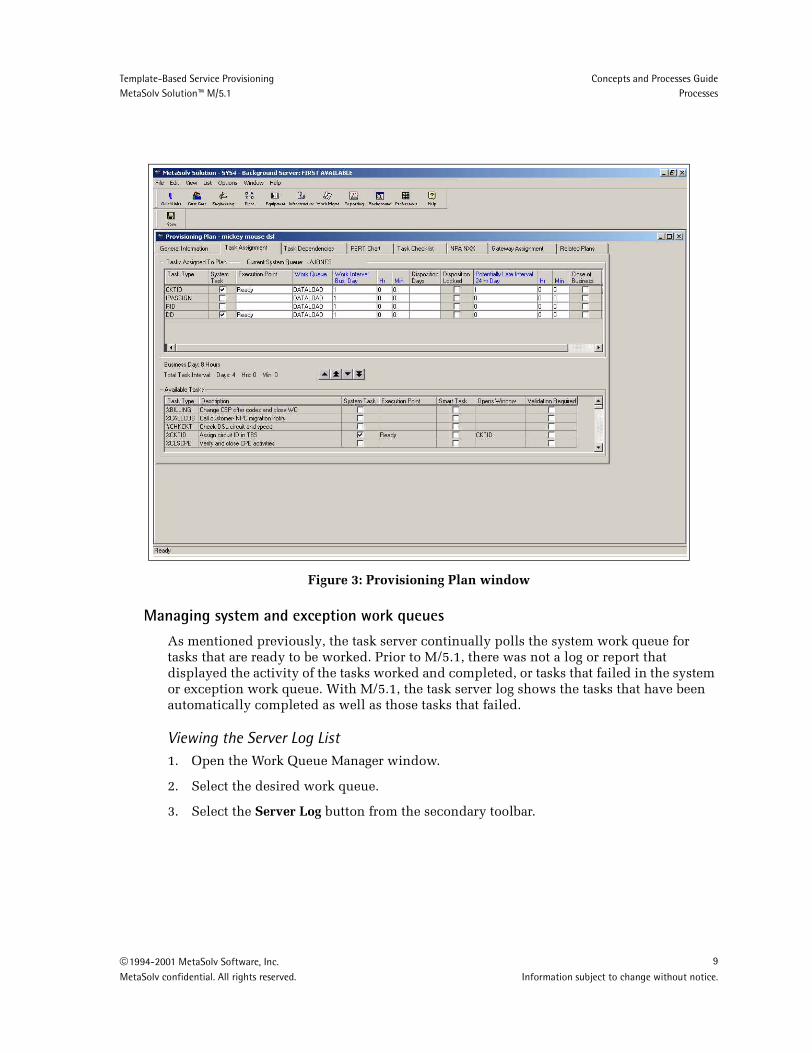
If a task has been changed to a system task, the changes are reflected when a new provisioning plan is created. It does not affect the task’s functionality in existing provisioning plans. To enable the new system task functionality, you must create a new provisioning plan with the updated task.
If a task type is designated as system task, this functionality can be overridden in the provisioning plan on an individual basis. If a task is a system task, the System checkbox will be checked in the Provisioning Plan window - Task Assignment tab. To override the system task functionality, uncheck the box.
8 1994-2001 MetaSolv Software, Inc.Information subject to change without notice. MetaSolv confidential. All rights reserved.
Template-Based Service Provisioning Concepts and Processes GuideMetaSolv Solution™ M/5.1 Processes
Figure 3: Provisioning Plan window
Managing system and exception work queues
As mentioned previously, the task server continually polls the system work queue for tasks that are ready to be worked. Prior to M/5.1, there was not a log or report that displayed the activity of the tasks worked and completed, or tasks that failed in the system or exception work queue. With M/5.1, the task server log shows the tasks that have been automatically completed as well as those tasks that failed.
Viewing the Server Log List1. Open the Work Queue Manager window.
2. Select the desired work queue.
3. Select the Server Log button from the secondary toolbar.
1994-2001 MetaSolv Software, Inc. 9
MetaSolv confidential. All rights reserved. Information subject to change without notice.

Template-Based Service Provisioning Concepts and Processes GuideProcesses MetaSolv Solution™ M/5.1
Figure 4: Server Log List window
The tasks that fail are sent to the exception work queue. The Server Log List provides the person responsible for working the exception queue with a reason as to why the task failed. The tasks must be reassigned or worked manually. Once the tasks in the exception queue have been worked and completed, a new, updated entry appears in the server log list. Each task issue is recorded for historical purposes.
Within the task server log, there are several different functions that can be performed. These functions include:
Filter: Allows you to filter information in the server log.
Clear: Allows you to clear the server log (clear the information from the current view).
Purge: Allows you to purge or delete the cleared server log (performed after the server log has been cleared).
Restore: Allows you to restore any data to the server log that has been cleared, but not purged.
Service Request Connections windowThe Service Request Connections window replaces the Service Request Circuits window and now supports both connection identification and provisioning procedures in the MetaSolv Solution. Based on the task chosen in the Work Queue Manager, the window is the gateway to various functions.
Opening the Service Request Connections window1. Open the Work Queue Manager window.
2. Select the desired work queue.
3. Double-click either the CKTID, DLRD, or RID task.
10 1994-2001 MetaSolv Software, Inc.Information subject to change without notice. MetaSolv confidential. All rights reserved.

Template-Based Service Provisioning Concepts and Processes GuideMetaSolv Solution™ M/5.1 Processes
Double-click optionsThe type of connection you double-click determines the resulting action:
Double-click an existing virtual circuit to display the VLR window.
Double-click an existing physical circuit to display the Circuit Design Maintenance window.
Double-click a physical connection to open the Physical Connection Design window.
Double-click a virtual connection to open the GLR window.
The Service Request Connections window supports traditional circuits, physical connections, virtual connections, and group connections. If the type column is null, the row is a circuit.
Toolbar menu optionsDepending on the order activity or order type, the following options display on the toolbar:
Cancel Assignment: Supported for all connection types.
Group Disconnect: Supported for all connection types.
Cancel Disconnect: Supported for all connection types.
Cancel/Change: Support TBD.
Group Print: Supported for all connection types. The CLR, DLR and/or GLR for all circuits and connections that appear in the Service Request Connections window can be printed using the group print functionality.
Group Assignment: Not supported for physical or virtual connections.
Figure 5: Service Request Connections window from the CKTID task
New filtering functionality has been added to the Service Request Connections window when it is opened from the DLRD or RID task. By making a selection from one of the drop-down boxes, connections can be filtered by:
1994-2001 MetaSolv Software, Inc. 11
MetaSolv confidential. All rights reserved. Information subject to change without notice.

Template-Based Service Provisioning Concepts and Processes GuideProcesses MetaSolv Solution™ M/5.1
Status: Current operational state of a circuit/connection. Examples include In Service, Pending, In Progress, or Pending Disconnect.
Type: Connections can be filtered by selecting all, physical, or virtual.
Category: Type of connection. For example, all, bandwidth virtual, facility, special, trunk, data, or video.
Figure 6: Service Request Connections window from the DLRD/RID task
Filtering for a specific circuit/connection type1. Open the Service Request Connections window.
2. Do one or a combination of the following:
Select a connection status from the Status drop-down.
Select a connection type from the Type drop-down.
Select a connection category from the Category drop-down.
The default selection is All.
Connection identificationFor template-based services, connection identification is the process of assigning identifiers (connection IDs) and providing additional information to describe the connections on a product service request or network drawing that contains either of the following:
A physical or virtual connection
12 1994-2001 MetaSolv Software, Inc.Information subject to change without notice. MetaSolv confidential. All rights reserved.

Template-Based Service Provisioning Concepts and Processes GuideMetaSolv Solution™ M/5.1 Processes
A combination of new connections and traditional circuits.
You must create a connection ID before you can design the connection or activate the service. This task is performed by provisioning staff, customer service representatives (CSRs), or anyone responsible for designing network connections.
Features and functionality
Default connection ID format
MetaSolv Software provides a default format for new connection IDs. You can use the default format or create one to fit your own naming conventions. You can also use established formats for new connections that follow traditional circuit types.
Following is an example of the default connection ID format:
CodeLoc1/CodeLoc2/LabelName/Seq#.
CodeLoc1 Required. By default, the system populates this value from the service request.
CodeLoc2 Optional. By default, the system populates this value from the service request. If a value was not provided on the service request, this value is omitted from the connection ID, however the value can be entered on the Connection ID window. If this value is provided it is not updated; however, location fields are updated.
Label name Originates from the template for a specific connection type
Seq# System generated to ensure the identifier is unique
Connection ID methods
MetaSolv Software provides the following mechanisms for assigning connection IDs:
Manual
Auto ID
Manual IDManually identify a connectionual to override the default connection ID format. The Auto ID checkbox in the Managing a Connection Spec window should be unchecked and the provisioning plan must include the CKTID task.
Note: Rules defined in MetaSolv Solution network templates affect how service provisioning works in your environment. To learn more about network templates, refer to the "Network Templates Concepts and Processes Guide."
Note: Currently, the MetaSolv Solution does not have the capability to create customized naming conventions for connection ids.
1994-2001 MetaSolv Software, Inc. 13
MetaSolv confidential. All rights reserved. Information subject to change without notice.

Template-Based Service Provisioning Concepts and Processes GuideProcesses MetaSolv Solution™ M/5.1
Auto ID Check the Auto ID checkbox in the Managing a Connection Spec window to use the default connection ID format. The CKTID task must also be designated as a system task.
If a combination of AUTO ID connections and manual ID connections exist for the service request, the CKTID is sent to the designated work queue. When the Service Request Connections window is opened, both types of connections appear. Auto ID connections display their ID in the Identification column.
Connection ID windowThe Connection ID window displays detailed information for a physical or virtual connection on a service request. Only group, physical, and virtual connections are identified in the Connection ID. Existing circuits will use the existing Circuit ID window. The field information is populated from the service request when available.
If the service you are provisioning contains a connection or a combination of connections and existing circuits, the CKTID task must be included in the provisioning plan.
Opening the Connection ID window from the Service Request Connections window
Double-click a connection on the Service Request Connections window.
Opening the Connection ID window from network design
1. Select a line on the network drawing (between two elements) where you want to add the connection.
2. Open the properties of the line and select the Hierarchy tab.
3. Select the connection type to be added from the hierarchy.
4. Select the Add New Connection option.
The Connection ID window opens.
The connection format dictates what fields appear on the Connection ID window. For example, if the connection format is OTS, then fewer fields will appear than CLS.
Note: When setting up your provisioning plan, add the CKTID task before adding the DLRD or RID task.
14 1994-2001 MetaSolv Software, Inc.Information subject to change without notice. MetaSolv confidential. All rights reserved.

Template-Based Service Provisioning Concepts and Processes GuideMetaSolv Solution™ M/5.1 Processes
Procedures
Creating a connection ID with the manual ID method
Indications for useUse the manual identification method when you want to override the default connection ID format. For circuits, assign a circuit ID to a bandwidth circuit prior to assigning VC circuits. For connections, assign IDs to group connections, then physical, then virtual.
Prerequisite tasksManual ID can be used if the service request meets the following criteria:
Auto identification has not been set up for the connection spec in network design.
The provisioning plan associated with the service request includes the CKTID task.
All task dependencies on the provisioning plan have been completed.
Steps1. Double-click a connection on the Service Request Connections window to open the
Connection ID window.
2. Select a value from the Connection Type drop-down or use the default selection. The steps that follow will be based on the format selected.
Accept the default value, OTS, for new connection types or to use a free-form connection ID.
Select any other connection type to open a circuit identification window with a connection ID format and fields appropriate for that type, for example CLF for facility connections and CLS for special connections.
MetaSolv Software automatically populates some fields on this window from values on the service request. All other required fields must be entered at this window before the information can be saved.
3. Enter a connection ID and any additional information about the connection, or accept the default values.
MetaSolv Software validates the data, checks for duplicate connection IDs, and stores the connection ID information in the database.
4. Open the Work Queue Manager window.
5. Double-click the CKTID task to open the Service Request Connections window (for PSR).
The Service Requests Connections window lists both circuits and connections on the order.
1994-2001 MetaSolv Software, Inc. 15
MetaSolv confidential. All rights reserved. Information subject to change without notice.

Template-Based Service Provisioning Concepts and Processes GuideProcesses MetaSolv Solution™ M/5.1
6. Do one of the following:
If there is no information in the Connection ID field, right-click and select New from the pop-up menu. You must build a physical connection before you can build a virtual connection.
If a connection ID exists for the connection, you can double-click the connection to open the Connection Identification window to maintain existing information.
7. Complete the information on the Connection Identification window.
When the Category field on the Service Request Connections window is Bandwidth, Special, or Facility, the following formats are valid on the Connection Identification window: CLS, OTS, CLF, or OTF. If the category is PVC, the following formats are valid: CLS, OTS, CLT, or OTT. For all other categories, CLS and OTS are the valid formats. The connection type determines what you see in the Connection ID field.
8. Click OK.
If the task is not assigned to the system task server (either because there are circuits or connections that require manual identification on the order, the queues are not available, or the you didn't assign it to the system work queue) the connections marked as Auto ID connections are assigned a connection ID when the user double clicks the CKTID task in their work queue. If there are circuits or connections that require manual identification on the order as well, you must do the manually process these.
Creating a connection ID with the auto ID method
After you enter an order for a system product with connections (or a standalone connection), you can add connection IDs using the Connection Identification window. The CKTID task is assigned to the system work queue if the order contains only connections that can have IDs automatically assigned. (The template with which a connection is associated determines whether or not a connection ID can be automatically assigned.) If the order contains circuits, or connections requiring manual assignment of IDs, the CKTID task must go into a user’s work queue. Appropriate connections are assigned an ID automatically when the tasks in the system queue or regular work queue are worked.
During connection identification, it is not necessary to enter the Z location Z. For example, if the connection is a DSL link, the location can be added at design time. If the connection ID is for an Enterprise connection (customer site - customer site) and both Location A and Z is already known, both the Location fields will auto-populate.
To find the correct Z location, use the button next to the Location Z field. Click OK after the connection ID has been completed.
PrerequisitesAuto ID can be used if the service request meets the following criteria:
Auto identification has been set up for the connection on the network template (the Auto ID checkbox in the connection spec is checked.)
16 1994-2001 MetaSolv Software, Inc.Information subject to change without notice. MetaSolv confidential. All rights reserved.

Template-Based Service Provisioning Concepts and Processes GuideMetaSolv Solution™ M/5.1 Processes
The provisioning plan associated with the service request includes the CKTID task as a system task.
All task dependencies on the provisioning plan have been completed.
The following steps occur when the CKTID task is activated:
1. The CKTID task is sent to the system work queue.
2. Connection IDs are automatically be generated.
The system task server initiates the connection identification task. MetaSolv Software validates the data, checks for duplicate connection IDs, and stores the connection ID information in the database. If the validation process fails, the request is sent to the exception queue where it can be reinitiated or worked manually.
3. The CKTID task automatically completes.
4. The CKTID's follower task changes to a Ready status
Making a connection eligible for Auto IDIn order to use the auto id functionality during provisioning in the CKTID task, the connection spec must be related to a network design and the Auto ID box must be checked.
Figure 7: Managing a Connection Spec window in Network Templates
Steps1. Open the Network Template Maintenance window.
2. Select the Connection Specs panel.
3. Select and double-click a connection spec from the treeview list.
4. Check the Auto ID checkbox.
5. Click OK.
1994-2001 MetaSolv Software, Inc. 17
MetaSolv confidential. All rights reserved. Information subject to change without notice.

Template-Based Service Provisioning Concepts and Processes GuideProcesses MetaSolv Solution™ M/5.1
Modifying a connection ID
You can modify/delete a circuit or connection on the Service Request Connections window (for PSR) only if it is not "In Service."
To delete a circuit or connection that is In Service, choose disconnect from the Product Service Request window - Service Items tab.
PrerequisitesOnly circuits or connections with a status of pending may be modified or deleted.
18 1994-2001 MetaSolv Software, Inc.Information subject to change without notice. MetaSolv confidential. All rights reserved.

Template-Based Service Provisioning Concepts and Processes GuideMetaSolv Solution™ M/5.1 Processes
Physical connection designFor service provisioning, physical connection design is the process of associating a physical connection with a service provider’s network or a customer-ordered network.
You must use this process to design specific types of physical connections, for example bandwidth connections, before you can provision services (virtual connections within the network). This task is performed by provisioning staff, customer service representatives (CSRs), or anyone responsible for designing network connections.
Features and functionality
Design methods
You must design physical connection manually.
Supported capabilities
Physical connection design supports the following capabilities, depending on the connection type being designed:
Plant assignments, including fiber
Port address assignments
Enabled port address (EPA) assignments
Channel assignments
Protected network routes
User-defined routes
DLC assignments
Premise equipment (pseudo-assignment when equipment is not inventoried)
Pri Term (pseudo-assignments)
Sec Term (pseudo-assignments)
Auto Design is supported for physical connections in the same way it has been supported prior to 5.1
For new connection types:
Customized attributes are viewable, and editable, if designed as such.
Association of customer connections and customer elements to networks is supported.
Network extensions
You can design physical connections as part of a network or as customer connections to a network system, for example DSL. MetaSolv Software checks for ownership and roles
Note: To successfully design a physical connection you must be able to determine terminating points, whether they are part of the system or are network extensions.
1994-2001 MetaSolv Software, Inc. 19
MetaSolv confidential. All rights reserved. Information subject to change without notice.

Template-Based Service Provisioning Concepts and Processes GuideProcesses MetaSolv Solution™ M/5.1
(defined within the templates for the specific connection type) and associates the extension to a network. Physical connection design supports those physical connections that are part of a network or connections that extend out to the customer.
Connection design tasks
You can access the design for connections from the work queue or from the network drawing.
From Work Management, double-click the DLRD or RID task within the work queue.
From Engineering, double-click the connection ID in the connection query results list.
From Network Design, select the Connection ID and open the design.
Related windowsThe windows you will use to complete the connection design process are:
Physical Connection Design window
Network System/Element Query window
Physical Connection Design window
Use this window to:
Design the physical connection
Capture specific design information
Associate a physical connection with a system if the connection is a customer connection.
Support entry and display of custom attributes
20 1994-2001 MetaSolv Software, Inc.Information subject to change without notice. MetaSolv confidential. All rights reserved.
Template-Based Service Provisioning Concepts and Processes GuideMetaSolv Solution™ M/5.1 Processes
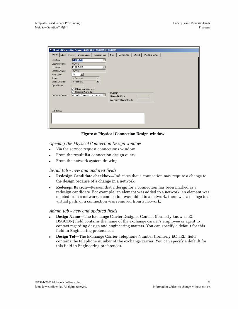
Figure 8: Physical Connection Design window
Opening the Physical Connection Design windowVia the service request connections window
From the result list connection design query
From the network system drawing
Detail tab - new and updated fieldsRedesign Candidate checkbox—Indicates that a connection may require a change to the design because of a change in a network. Redesign Reason—Reason that a design for a connection has been marked as a redesign candidate. For example, an element was added to a network, an element was deleted from a network, a connection was added to a network, there was a change to a virtual path, or a connection was removed from a network.
Admin tab - new and updated fieldsDesign Name—The Exchange Carrier Designer Contact (formerly know as EC DSGCON) field contains the name of the exchange carrier's employee or agent to contact regarding design and engineering matters. You can specify a default for this field in Engineering preferences.
Design Tel—The Exchange Carrier Telephone Number (formerly EC TEL) field contains the telephone number of the exchange carrier. You can specify a default for this field in Engineering preferences.
1994-2001 MetaSolv Software, Inc. 21
MetaSolv confidential. All rights reserved. Information subject to change without notice.

Template-Based Service Provisioning Concepts and Processes GuideProcesses MetaSolv Solution™ M/5.1
Design tab - new and updated fieldsThis tab is disabled for physical connection design. The information is captured on the Location Information tab.
Custom Attributes tab - new and updated fieldsAny value or custom attribute that is defined and associated with the connection spec appears on this window.
Figure 9: Physical Connection Design window - Custom Attributes tab
Network tab - new and updated fieldsChild Element—terminating end of a connection. An element is marked as a child when it is the second element selected within the network design canvas to create an element relationship. It becomes the 'connect to' element.
Network System—name given by the user to identify a network.
Parent Element—terminating end of a connection. An element is marked as parent when it is the first element selected within the network design canvas to create an element relationship. It becomes the 'connect from' element.
22 1994-2001 MetaSolv Software, Inc.Information subject to change without notice. MetaSolv confidential. All rights reserved.

Template-Based Service Provisioning Concepts and Processes GuideMetaSolv Solution™ M/5.1 Processes
Figure 10: Physical Connection Design window - Network tab
Network System/Element Query window
The Network Association Response window allows the user to associate customer connections with the network systems and elements.
Opening the Network System/Element Query windowClick the design lines tab. This will only open if no information about the system can be determined or if more than one system and/or element is associated with the connection.
Right-click from the design lines.
1994-2001 MetaSolv Software, Inc. 23
MetaSolv confidential. All rights reserved. Information subject to change without notice.

Template-Based Service Provisioning Concepts and Processes GuideProcesses MetaSolv Solution™ M/5.1
Figure 11: Network System/Element Query window
Associating a connection with a network system or element1. Open the Connection Design Query window.
2. Query for a physical connection.
3. On the Results tab, double-click the connection.
4. Select the Network tab. The system automatically associates the connection with a network system/element based on the template rules.
5. If no association can be made and the tab is blank, click the List button.
The Network System/Element Query window opens.
6. Enter search criteria, and click Retrieve.
7. Select and double-click a network system/element.
The selection appears on the Network tab.
8. To modify an association, select the network system/element, and click Delete. Perform steps 5 through 7.
If the List button is disabled, the system is not able to associate the connection to a network system or element. The association must be made in Network Design.
You must use network design task to make associations to a network system for physical connections that are part of a system.
24 1994-2001 MetaSolv Software, Inc.Information subject to change without notice. MetaSolv confidential. All rights reserved.

Template-Based Service Provisioning Concepts and Processes GuideMetaSolv Solution™ M/5.1 Processes
Procedures
Designing customer connections
PrerequisitesThe template containing customer connections is defined if a network system exists.
Steps1. Click in the Physical Connection Design window - Design Lines tab, or from the
network drawing.
2. MetaSolv Software looks for a network area and/or system.
If Loc2 is not identified it looks for the network areas serving Loc1. We force Loc1 to be the extension (here, not necessarily in other areas of MetaSolv Solution). We are not always serving end users (explain why this matters here).
If both locations are provided, the first is the system extension and the second is used to locate elements. If only one element is found the connection is made.
3. If multiple network areas and/or elements exist, MetaSolv Software prompts you to specify which component/system to use in making the association. Confirm to display the Network Association Response window:
If the System/Component/Location grid is populated, you can make a selection.
If the grid is blank, the Network System Component Query window displays and you can search for a system/component by System Name, Location (known today as Coded Location), Location Name, City, or State. When the grid displays again, you can make selections.
4. Right-click from the Design Lines tab to re-initiate this process and make additional associations. If you are designing a physical connection as part of a network extension and there are no system/component associations, you will be forced to query for an existing element.
Tip: When designing physical connections in this manner you would not do equipment assignments in network areas.
Designing connections as part of a system
Use this method when designing bandwidth connections in a VPN. For example, when a physical connection is not part of an extension.
You must use network design task to make associations to a network system for physical connections that are part of a system.
Note: MetaSolv’s software does not validate physical connections associated with systems.
1994-2001 MetaSolv Software, Inc. 25
MetaSolv confidential. All rights reserved. Information subject to change without notice.

Template-Based Service Provisioning Concepts and Processes GuideProcesses MetaSolv Solution™ M/5.1
Steps1. Right-click on the Physical Connection Design window - Design Lines tab, or from the
network drawing.
2. MetaSolv’s software looks for a connection.
If Loc2 is not identified it looks for the network areas serving Loc1. We force Loc1 to be the extension (here, not necessarily in other areas of MetaSolv Solution). We are not always serving end users.
If both locations are provided, the software uses components associated with those locations.
3. If multiple network areas and/or elements exist MetaSolv Software prompts you to specify which element/system to use in making the association.
If the System/Component/Location grid is populated, you can make a selection.
If the grid is blank, the Network System Component Query window displays and you can search for a system/component by System Name, Location (known today as Coded Location), Location Name, City, or State. The grid displays the results from the query. Now selections can be made from the window.
4. Right-click from the Design Lines tab to re-initiate this process and make additional associations.
Bandwidth Allocation Report for connectionsThe Bandwidth Allocation Report for connections lists information about all virtual connections allocated to a given bandwidth connection as well as information about each allocation.
New and updated fieldsMaximum/Minimum Threshold—Product of the bandwidth connection’s bit rate and the threshold value.
Predefined CAs—Some custom attributes are included with the software, while others may be user-defined.
PrerequisitesThe columns in the Bandwidth Allocation report are based on the Transmission Speed and Capacity Tracking custom attribute categories. The system administrator determines which custom attributes appear on the report. If no data has been selected, the system runs a default report based on the connection information.
Viewing/printing the reportThe Bandwidth Allocation report can be generated from several areas within the application.
26 1994-2001 MetaSolv Software, Inc.Information subject to change without notice. MetaSolv confidential. All rights reserved.

Template-Based Service Provisioning Concepts and Processes GuideMetaSolv Solution™ M/5.1 Processes
From the Physical Connection Design Query window
1. Open the Connection Design Query window.
2. Select the Include Bandwidth checkbox or any category code that includes bandwidth information, and enter search criteria on the Criteria tab.
3. Click the Retrieve button.
4. Double-click a connection on the Results tab.
5. Click the Band Alloc button on the secondary toolbar.
From the GLR window
1. Open the GLR window.
2. Right-click a connection on the canvas, and select Bandwidth Allocation Report from the pop-up menu.
From the Connection Hierarchy window
1. Open the Connection Hierarchy Query window.
2. Query for a connection.
3. Right-click a connection, and select Open>Bandwidth Allocations.
1994-2001 MetaSolv Software, Inc. 27
MetaSolv confidential. All rights reserved. Information subject to change without notice.

Template-Based Service Provisioning Concepts and Processes GuideProcesses MetaSolv Solution™ M/5.1
Virtual connection designYou must design the physical connections before you can provision a service over those connections. This task is performed by provisioning staff, customer service representatives (CSRs), or anyone responsible for designing next generation network connections. You can design virtual connections from the work queue (for ordered connections), results list of connection design query, or from the network drawing.
Process overviewFor template-based service provisioning, virtual connection design is the process of designing and maintaining information for virtual service technologies such as frame relay, asynchronous transfer mode (ATM), and Internet protocol (IP) permanent virtual circuts(PVCs) delivered over template-based networks. This module provides the ability to build an end-to-end service (virtual connection) by building and maintaining assignments and allocations between the physical and virtual connection. M/5.1 supports:
Path analysis locates available paths in the network.
Network templates determine what assignments and allocations are made along a path for a virtual connection.
Assignment of IP addresses to a virtual connection
Graphics used in graphical representation come from network design.
Allows user to access bandwidth reports..
Features and functionality
Design methods
MetaSolv Software provides the following mechanisms for designing virtual connections:
Manual assign—you can define a connections paththrough a network.
Path selection—you can select a path and make manual assignments.
Hard and soft connections—Supports both hard (specific route is defined within the provider’s network) and soft (network determines routing when the service is used) assignments through a network which display similarly to the current VLR. That is, access to a network (cloud) and out of the network. Hard assignments will display access into and out of the network as well as all assignments and allocations within the network (cloud).
Note: To successfully design a connection you must be able to determine terminating points for the virtual connections, and which physical connections (whether they are part of the system or are network extensions) terminate at the component end points.
Note: Rules defined in MetaSolv Solution network templates affect how service provisioning works in your environment. To learn more about network system templates, refer to "Network Templates Concepts and Processes Guide."
28 1994-2001 MetaSolv Software, Inc.Information subject to change without notice. MetaSolv confidential. All rights reserved.

Template-Based Service Provisioning Concepts and Processes GuideMetaSolv Solution™ M/5.1 Processes
Provisioning Dialog
The Provisioning Dialog helps facilitate the provisioning process by leading you through the network assignments for a virtual connection. This feature provides:
Bandwidth allocations to connections
Assignments to port addresses
The Provisioning Dialog supports the following capabilities:
Path Analysis—You have the ability to display all paths with available capacity through a network for a connection. You can specify in preferences whether paths are prioritized by the least number of hops or by shortest distance.
Custom Attributes—You can capture dependencies and values about allocations and connections. Custom Attributes are characteristics for network systems, elements, connections, and allocations of connections within a system.
Template Rules—Template rules determine paths and assignments, and define the types of elements and connections that make up a network.
Manual Design—This allows you to select a path for a connection and make assignments along the selected path.
Bandwidth Allocation—This enables you to validate bandwidth allocation and to specify the allocation values. Examples include VPI/VCI or DLCI.
Related windowsGLR
Properties window for Elements
Properties window for Connections
Custom Attributes window
GLR
GLR (Graphical Layout Record) is a generic term used to refer to two items in the application: the GLR window and the GLR report. In provisioning, the GLR window displays a graphical and logical representation of a connection showing its path through elements within network systems and also elements outside the confines of the network systems. You provision virtual connections in the GLR window.
The GLR report provides information about a specific virtual connection, such as administrative information, design lines, and a graphical-view of design.
1994-2001 MetaSolv Software, Inc. 29
MetaSolv confidential. All rights reserved. Information subject to change without notice.

Template-Based Service Provisioning Concepts and Processes GuideProcesses MetaSolv Solution™ M/5.1
Figure 12: GLR window - Provisioning Dialog panel
The GLR allows for physical assignments and allocations of the virtual connection. Both a textual and a graphical view of the connection are represented within the GLR. In addition, a provisioning dialog is used to walk you through each assignment or allocation of the connection design.
Use this window to:
Provision a virtual connection to a network system
View a text view of the connection design
View a graphical representation of the connection design
Opening the GLR windowThe GLR window can be opened from many areas within the application.
From the main toolbar
1. Click the Engineering button.
2. Click the Conn Des button.
3. Enter search criteria for the virtual connection on the Criteria tab.
4. Click the Retrieve button.
30 1994-2001 MetaSolv Software, Inc.Information subject to change without notice. MetaSolv confidential. All rights reserved.

Template-Based Service Provisioning Concepts and Processes GuideMetaSolv Solution™ M/5.1 Processes
5. Double-click the connection you want to view.
From the task manager
1. Click the Work Mgmt button on the main toolbar.
2. Click the Queue Mgr button on the Work Management toolbar.
3. Select the desired work queue.
4. Double-click either the DLRD or RID task.
5. Double-click the virtual connection you want to view.
From network design
1. Open the Network Design window.
2. Select and open a network template from the Network List panel.
3. Right-click a connection between two elements on the canvas, and select Properties from the pop-up menu.
4. From the Managing a Connection window, double-click a virtual connection.
1994-2001 MetaSolv Software, Inc. 31
MetaSolv confidential. All rights reserved. Information subject to change without notice.

Template-Based Service Provisioning Concepts and Processes GuideProcesses MetaSolv Solution™ M/5.1
GLR Window ToolbarAll the buttons listed below are available on the GLR window. These buttons help you view and save data, design virtual connections, and navigate through the provisioning dialog.
Activation Report - Displays the Activation Report. You can print or preview the report, activate non-ordered connections, and view gateway events.
Mark as Record Issued- Marks the design “record issued.” This is the last step before completing the design task.
Next Step - Moves to the next step in the Provisioning Dialog. This button is only available when a connection is being designed for the first time. When a connection is marked as Record Issued or In Service, changes are saved using the Save button.
Previous Step - Returns to the previous step in the Provisioning Dialog.
Print - Prints the GLR report. You can preview the report, change the printer, or print the report from the Design Print window.
Print Preview - Displays the GLR report. You preview or print the report from the Design Print Preview window.
Redesign - Clears the design information.
Save - Saves any changes made in the GLR window. This button is only available after the terminating element is selected.
Save As New Issue - Saves the design as a new issue. To save a new design issue, the design must be marked Current or all the steps in the Provisioning Dialog are complete.
Zoom In - Enlarges the graphic design.
Zoom Out - Reduces the graphic design.
32 1994-2001 MetaSolv Software, Inc.Information subject to change without notice. MetaSolv confidential. All rights reserved.

Template-Based Service Provisioning Concepts and Processes GuideMetaSolv Solution™ M/5.1 Processes
Figure 13: GLR window toolbar
Properties window for elements
This is a view-only window. No field information can be updated or changed.
Figure 14: View an Element window
Opening the View an Element window1. Open the GLR window.
2. Select Provisioning Dialog from the panel list.
3. Select an element on the canvas.
4. Right-click and select Properties from the pop-up menu.
Select and Zoom In - Allows you to capture and enlarge several elements on the canvas at one time. Click the button and draw an area around the desired elements.
Select and Zoom Out - Allows you to capture and decrease the size of several elements on the canvas at one time. Click the button and draw an area around the desired elements.
Show/Hide Docked Panel - Displays or hides the docked panel. The docked panel contains the Provisioning Dialog, Administrative Section, Available Connections, and Design Mode.
Show/Hide Menu and Tool Icons - Displays or hides the main toolbar and menus.
1994-2001 MetaSolv Software, Inc. 33
MetaSolv confidential. All rights reserved. Information subject to change without notice.

Template-Based Service Provisioning Concepts and Processes GuideProcesses MetaSolv Solution™ M/5.1
Viewing properties for connections
This is a view-only window. No field information can be updated or changed.
Viewing physical connection design information from the GLR1. Open the GLR window.
2. Select Provisioning Dialog from the panel list.
3. Select a connection on the canvas.
4. Right-click and select Open Connection Design from the pop-up menu.
The Physical Connection Design window opens.
Note: You can toggle between the windows or close the Physical Connection Design window to return to the GLR window.
34 1994-2001 MetaSolv Software, Inc.Information subject to change without notice. MetaSolv confidential. All rights reserved.

Template-Based Service Provisioning Concepts and Processes GuideMetaSolv Solution™ M/5.1 Processes
Custom Attributes window
Under Development
Figure 15: Custom Attributes step in the GLR window
Viewing custom attributes in the GLR1. Open the GLR window.
2. Select Provisioning Dialog from the panel list.
3. Select the Custom Attributes step.
1994-2001 MetaSolv Software, Inc. 35
MetaSolv confidential. All rights reserved. Information subject to change without notice.

Template-Based Service Provisioning Concepts and Processes GuideProcesses MetaSolv Solution™ M/5.1
Fields/columnsWhen you make a selection from the Virtual Broadband Service Category drop-down, your selection dictates what custom attributes appear in the window. All required fields are marked with a red arrow.
Procedures
Designing a virtual connection in the GLR window
Your existing PVCs need to be converted before you can use MetaSolv Solution 5.1. If you have not converted your circuits and need to make modifications to an existing circuit, open the VLR.
To design a virtual connection1. Open the GLR window.
2. Select Provisioning Dialog from the panel list.
3. Select an originating element.
If only one originating element is available, the element is automatically selected.
4. Select a terminating element. If a terminating network has not been chosen, select a terminating network.
If only one terminating element or network is available, the element or network is automatically selected.
You must select a terminating network if two end points have not been chosen on the order.
5. Design the connection manually or select a path using path analysis.
6. View the custom attributes.
Warning: If you change the selection in the Virtual Broadband Service Category drop-down after data has been entered in the custom attributes fields, the information is lost. Save the design as a "new issue" before making any changes.
Note: For more information on the conversion process, please see MetaSolv’s Migration Guide v.5.1.
36 1994-2001 MetaSolv Software, Inc.Information subject to change without notice. MetaSolv confidential. All rights reserved.

Template-Based Service Provisioning Concepts and Processes GuideMetaSolv Solution™ M/5.1 Processes
7. Based on the network template, you may have to perform any combination of the following procedures:
Allocate bandwidth.
Make a port assignment.
Note: If no port assignments have been made, there will be nothing to view in the next two steps.
⇒ View design notes.
⇒ View design lines.
8. View the graphic design.
9. Mark the GLR as Record Issued.
The number of steps required is based on the network template. Each step must be completed in sequential order to build a connection.
1994-2001 MetaSolv Software, Inc. 37
MetaSolv confidential. All rights reserved. Information subject to change without notice.

Template-Based Service Provisioning Concepts and Processes GuideProcesses MetaSolv Solution™ M/5.1
Modifying the design mode in the GLR window
You can change how an individual connection is designed by changing the design mode on the Design Options panel in the GLR window before the design step.
Figure 16: GLR window - Design Options panel
To modify the design mode1. Open the GLR window.
2. Select Design Options from the panel list.
3. Select one of the following:
Manual Design
Path Analysis by Hops
Note: Enter the allowed number of hops in the Maximum Number of Hops field.
Path Analysis by Distance
38 1994-2001 MetaSolv Software, Inc.Information subject to change without notice. MetaSolv confidential. All rights reserved.

Template-Based Service Provisioning Concepts and Processes GuideMetaSolv Solution™ M/5.1 Processes
Note: The design mode must be changed before the design step.
Manually designing a virtual connection
Use this process to find all paths or to select a path between the two end points and make each assignment along that path for a manual connection design. This task is performed by service provisioning staff or anyone responsible for designing virtual connections. You must do this when designing a service to consume resources of a network system.
Ordering determines what information is available and what must be specified during the virtual connection design process. Components for successful design include:
Ability to determine terminating points for the connection
Ability to determine if the system’s physical connections provide transport
Ability to determine if the system’s virtual connection will be provisioned to consume resources
Manual design is used when designing a PVC.
When manually designing connections, you add hard connections or soft connections between elements. Hard connections allow you to manually select a connection between each set of elements until the design is complete. If soft connections are selected, the system attempts to draw a dashed line from the selected element to an element that either has no connections on it, (which would mean it is either a terminating or orignating element) or an element that has only one connection attached to it. A soft connection can only be drawn between two elements that share the same network.
1994-2001 MetaSolv Software, Inc. 39
MetaSolv confidential. All rights reserved. Information subject to change without notice.

Template-Based Service Provisioning Concepts and Processes GuideProcesses MetaSolv Solution™ M/5.1
Figure 17: GLR window - Available Connections panel
PrerequisitesTo manually design a virtual connection, do one of the following:
Check the Manual Design checkbox in the Design Mode preference.
Check the Manual Design checkbox on the Design Options panel in the GLR window for individual connections.
Designing a virtual connection using manual design1. Open the GLR window.
2. Select Provisioning Dialog from the panel list.
3. Select the Manual Design step.
4. Select the originating or terminating element on the canvas.
40 1994-2001 MetaSolv Software, Inc.Information subject to change without notice. MetaSolv confidential. All rights reserved.

Template-Based Service Provisioning Concepts and Processes GuideMetaSolv Solution™ M/5.1 Processes
5. Right-click the element, and select one of the following from the pop-up menu:
Add Hard Connection - Complete steps six through nine.
Add Soft Connection - Complete step ten.
6. Expand the appropriate treeview list in the Available Connections panel.
7. Select a connection ID from the treeview list.
8. Drag and drop the connection ID between the two elements on the canvas.
9. Repeat steps four through eight until the design is complete.
To remove a connection, right-click the connection, and select Remove Connection from the pop-up menu.
10. Click the Next or Save button on the toolbar.
A connection cannot be removed if another connection is dependent on it. For example, if you have an incomplete design with three elements, (A the originating element, B, and C), and two connections, the connection between elements A and B cannot be removed because the connection between elements B and C is dependent upon it. The connection between elements B and C can be removed because no other connections are dependent on it.
Using path analysis to design a virtual connection
PrerequisitesTo use path analysis to design a virtual connection, do one of the following:
Check the Path Analysis Distance or Path Analysis Hops checkbox in the Design Mode preference.
Check the Path Analysis by Distance or Path Analysis by Hops checkbox on the Design Options panel in the GLR window for individual connections.
Selecting a path for a virtual connection1. Open the GLR window.
2. Select Provisioning Dialog from the panel list.
3. Select the Path Analysis step.
4. Select a path from the canvas. To view the path information, expand the treeview on the canvas.
5. Click the Next or Save button on the toolbar.
1994-2001 MetaSolv Software, Inc. 41
MetaSolv confidential. All rights reserved. Information subject to change without notice.

Template-Based Service Provisioning Concepts and Processes GuideProcesses MetaSolv Solution™ M/5.1
Assigning IP addresses
IP addresses can now be assigned to virtual connections from the GLR window.
If you cannot assign or unassign the IP address, it is possible that the IP address has been inherited. An IP address is considered inherited when the IP address is assigned to a physical port on the originating or the terminating element. This would apply to an internet connection where the physical port on the IP router has an IP address assigned to it.
To assign an IP address1. Open the GLR window.
2. Select Provisioning Dialog from the panel list.
3. Right-click an originating or terminating element on the canvas, and select Assign IP Address from the pop-up menu. The Number Inventory Query window opens.
Note: An IP address cannot be associated with an intermediate element.
4. Query for an IP address.
The query looks at the originating or terminating elements on the canvas and returns IP addresses from the same subnet. For example, if you are trying to assign an IP address to the originating element, the query will look at the terminating element to see if it has an IP address.
5. Select an IP address from the query results.
6. Click OK.
7. Click the Next or Save button on the toolbar.
Making port assignments to a virtual connection
1. Open the GLR window.
2. Select Provisioning Dialog from the panel list.
3. Select the Port Assignment step.
4. Select an element name on the canvas, and click the plus (+) sign next to the element name to expand the hierarchy.
All available associated port addresses with the appropriate bit rate display for each element. A check appears beside port addresses that already have assignments.
5. Select one or more port addresses. A check appears beside the selected address.
6. Click the Next or Save button on the toolbar.
Note: For more information on IP address assignment rules, please see online help.
42 1994-2001 MetaSolv Software, Inc.Information subject to change without notice. MetaSolv confidential. All rights reserved.

Template-Based Service Provisioning Concepts and Processes GuideMetaSolv Solution™ M/5.1 Processes
Allocating bandwidth to a virtual connection
1. Open the GLR window.
2. Select Provisioning Dialog from the panel list.
3. Select the Allocate Bandwidth step.
4. Enter the appropriate values.
5. Click the Next or Save button on the toolbar.
Exporting a graphic canvas drawing
The graphic design of a virtual connection can be exported and saved.
To export a graphic canvas drawing1. Open a drawing in the Network Template Maintenance or Network Design window, or
open a connection in the GLR window.
2. Right-click the canvas and select Export Graphics from the pop-up menu.
3. Specify the filename and format, either BMP or EMF.
4. Click OK.
If you are saving the entire drawing to a BMP file and the estimated file size is greater than 1MB, a message appears and provides the option to continue or cancel the export.
Redesigning a virtual connection
1. Open the GLR window.
2. Select Provisioning Dialog from the panel list.
3. Select the Redesign button on the toolbar.
4. Modify the design.
5. Save the record as a new issue or override the existing information.
Note: When making port assignments or allocating bandwidth to a virtual connection, rules are based on the network template.
1994-2001 MetaSolv Software, Inc. 43
MetaSolv confidential. All rights reserved. Information subject to change without notice.

Template-Based Service Provisioning Concepts and Processes GuideProcesses MetaSolv Solution™ M/5.1
Modifying design contact information
The Administrative Section panel in the GLR window is used to update contact and note information for a virtual connetion.
Figure 18: GLR window - Administrative Section panel
To modify design contact information1. Open the GLR window.
2. Select Administrative Section from the panel list.
3. Update information in any of the following sections:
Contact information
Notes
4. Click the Save button on the toolbar.
44 1994-2001 MetaSolv Software, Inc.Information subject to change without notice. MetaSolv confidential. All rights reserved.

Template-Based Service Provisioning Concepts and Processes GuideMetaSolv Solution™ M/5.1 Processes
Reports
Port VC Limit Report
The Port VC Limit report provides information on the current virtual connections assigned to ports. It does not take into consideration the status of the port or the connection. The report returns information on all ports and connections whether the status is Assigned, Pending, Pending Disconnect, or Trouble. Either a percentage or a quantity can be used to filter the data. The report only returns information on ports that have a VC Limit specified.
PrerequisitesTo generate the report, you must first query for the Port VC limits. The query can be performed from several locations in the application.
Viewing/printing the reportThe report can be run from many different areas throughout the application.
From Equipment Install
1. Open the Equipment Install window.
2. Right-click a relay rack, shelf, card, or port assignment and select Open Port VC Limit Report from the popup menu.
3. Enter a percentage number or a number of virtual circuits in the number input field.
4. Select the Filter by VC Percentage or the Filter by Quantity radio button, depending on how you want to filter the query.
5. Click the Submit button.
The Port VC Limit Report Query window returns the results.
6. Click the Print or Close button.
From the GLR
1. Open the graphic design in the GLR.
2. Right-click a graphical element and select Open Port VC Limit Report from the popup menu.
3. Enter a percentage number or a number of ports in the number input field.
4. Select the Filter by VC Percentage or the Filter by Quantity radio button, depending on how you want to filter the query.
5. Click the Submit button.
The Port VC Limit Report Query window returns the results.
6. Click the Print or Close button.
1994-2001 MetaSolv Software, Inc. 45
MetaSolv confidential. All rights reserved. Information subject to change without notice.

Template-Based Service Provisioning Concepts and Processes GuideProcesses MetaSolv Solution™ M/5.1
From the Connection Design window
1. Query for a bandwidth connection.
2. Double-click the desired bandwidth connection design.
Note: The bandwidth connection design cannot be in a Pending state.
3. Click the VC Limit button on the secondary toolbar.
4. Enter a percentage number or a number of ports in the number input field.
5. Select the Filter by VC Percentage or the Filter by Quantity radio button, depending on how you want to filter the query.
6. Click the Submit button.
The Port VC Limit Report Query window returns the results.
7. Click the Print or Close button.
GLR
The GLR report provides information about a specific virtual connection. This report is useful if you need the following information:
Administrative contacts
Custom attributes
Design details
Design lines
Graphical-view of design
Viewing/printing the GLR1. Open the GLR window.
2. Click the Print or Print Preview button on the toolbar.
46 1994-2001 MetaSolv Software, Inc.Information subject to change without notice. MetaSolv confidential. All rights reserved.

Template-Based Service Provisioning Concepts and Processes GuideMetaSolv Solution™ M/5.1 Processes
Service Activation
Under Development
Service activation is the series of cmommands that enable connections to work or be "turned up."
Features and functionalityService may be activated through the generation of the activation report or through other associated work tasks and gateway events. All other design tasks, i.e. CKTID, DLRD, RID, should be completed before service is activated.
Ordered connections
When the activation report is generated, the Activate button is disabled. Service is activated through the ACTIVATE task created in the provisioning plan.
Non-ordered connections
Physical and virtual non-ordered connections can be activated from the Activation Report. You can also view the associated gateway events and reactivate them if necessary.
Procedures
Activating non-ordered connections and viewing gateway events
1. Open the Activation Report.
2. Click the Activate button.
The gateway events are sent for the non-ordered connection.
3. Click the Gateway Event button.
The status of the gateway events appears. Right-click a gateway event to reactivate it.
Activation reportThe activation report provides information on network connections and network elements, and can be used to activate connections, line products, and internet products including:
Signaling information for dial-tone line products
Items that need to be provisioned from a PSR order for:
⇒ Internet dial-up service
⇒ Internet circuits
⇒ Network connections
1994-2001 MetaSolv Software, Inc. 47
MetaSolv confidential. All rights reserved. Information subject to change without notice.

Template-Based Service Provisioning Concepts and Processes GuideProcesses MetaSolv Solution™ M/5.1
⇒ Network elements
⇒ Web hosting
The report is a combination of information used in the tech translation sheets from previous versions of the MetaSolv Solution. The Activation report is useful if you want to know the following kind of information:
Customer account specifications
Email service specifications
Internet service specifications
Web hosting service specifications
Figure 19: Activation Report
The TRANS task should be included in your provisioning plan.
Viewing/printing the reportThe activation report can be run from many different areas throughout the application. The results of the report will vary based on the location of the window when the report is generated. The report results will be either order-based, connection-based or service item-based.
From Work Management
1. Click the Work Management button.
2. Click the Queue Manager button.
3. Locate the queue you want to view, and double-click the TRANS task.
48 1994-2001 MetaSolv Software, Inc.Information subject to change without notice. MetaSolv confidential. All rights reserved.

Template-Based Service Provisioning Concepts and Processes GuideMetaSolv Solution™ M/5.1 Processes
4. Select the non-premise product you want to view.
5. Click the Activation Report button.
From PSR
1. Open the Product Service Request window and select the Service Items tab.
2. Select the Installed Service Items radio button.
3. Highlight the appropriate network connection, network element, or network system.
4. Click the Item Info tab.
5. Select the Activation Report from the drop-down.
From Order Management
1. Open the Service Request Search Window.
2. In the Search By area, select PSR and Service Request from the drop-downs.
3. Select the appropriate order status buttons and enter the applicable search criteria.
4. Click Retrieve.
5. When the Results tab appears, select the Product History tab.
6. Highlight the network connection, network element, or network system you want to view.
7. Select Activation Report from the drop-down.
From Customer Account
1. From the Customer Account window, click the Product History tab.
2. Highlight the appropriate network connection, network element, or network system.
3. Select the Activation Report from the drop-down.
From the GLR window
1. Open the GLR window.
2. Select the Activation Summary Report button from the toolbar.
From Network Design
1. Open a network system.
2. Select the Activation Summary Report button from the canvas toolbar.
1994-2001 MetaSolv Software, Inc. 49
MetaSolv confidential. All rights reserved. Information subject to change without notice.

Template-Based Service Provisioning Concepts and Processes GuideProcesses MetaSolv Solution™ M/5.1
From Customer Profile
1. Open the Customer Summary window.
2. Do one of the following depending on which type of report you want to generate:
Click the Network Systems link in the navigation pane.
Click the Network Elements link in the navigation pane.
Click the Circuits/Connections link in the navigation pane.
Click the Telephone Numbers link in the navigation pane.
3. From the "Do you want to create an order for any of these network systems, network elements, circuits/connections, or telephone numbers?" page, do one of the following depending on which type of report you want to generate.
For network systems, click the short name link. The status of the network system must be "In Service," "Disconnect," or "Suspend."
For network elements, click the short name link. The status of the network element must be "In Service."
For connections, click the Alias/Type link. The status of the connection must be "In Service," "Disconnect," or "Suspend."
For telephone numbers, click the telephone number link. Note: The status of the telephone number must be "In Service," "Disconnect," or "Suspend."
50 1994-2001 MetaSolv Software, Inc.Information subject to change without notice. MetaSolv confidential. All rights reserved.

Template-Based Service Provisioning Concepts and Processes GuideMetaSolv Solution™ M/5.1 Processes
Connection queriesConnection queries allow you to query for:
circuits or connections
circuit/connection design information
circuit/connection hierarchy information.
Related windowsThe following windows support provisioning procedures in the MetaSolv Solution:
Connection Design Query window
Connection Hierarchy Query window
Connection Design Query window
Figure 20: Connection Design Query window
The only custom attribute criteria that can be used in a query is bit rate. Queries based on bit rates can appear to produce incorrect results. Connection queries are not issue specific. A bit rate query may seem to produce incorrect results because the custom attribute (CA) bit rates are tied to a service item and can be changed across different issues of the design.
For example, service item 1001 could use a CA bit rate of 1.344M on issue 1, but on issue 2, it could use a CA bit rate of 1.544M. If you query for a bit rate of 1.344M, the results produce the connection associated with issue 1. If issue 2 is opened, 1.544M appears as the bit rate, making it look like the query did not work correctly. The query did work correctly because service item 1001 has a CA bit rate of 1.344M on issue 1.
1994-2001 MetaSolv Software, Inc. 51
MetaSolv confidential. All rights reserved. Information subject to change without notice.

Template-Based Service Provisioning Concepts and Processes GuideProcesses MetaSolv Solution™ M/5.1
Opening the Connection Design Query window1. Click the Engineering button on the main toolbar
2. Click the Conn Des button on the secondary toolbar.
If zero appears in the Issue field, there are no previous designs.
New and updated fieldsAny additional Include fields that appear are user-defined categories. These categories are defined in network templates. For example in Figure 21, the system administrator created a group called Admin Groups. If the field is selected, the query will search for a collection connections.
Connection Hierarchy Query window
Figure 21: Connection Hierarchy Query window
Opening the Connection Hierarchy Query window1. Click the Engineering button on the main toolbar.
2. Click the Conn Hier button on the secondary toolbar.
52 1994-2001 MetaSolv Software, Inc.Information subject to change without notice. MetaSolv confidential. All rights reserved.

Template-Based Service Provisioning Concepts and Processes GuideMetaSolv Solution™ M/5.1 Processes
New and updated fieldsAny additional Include fields that appear are user-defined categories. These categories are defined in network templates. For example in Figure 22, the system administrator created a group called Admin Groups. If the field is selected, the query will search for a collection connections.
Procedures
Viewing existing circuit/connection designs
1. Open the Connection Design Query window.
2. Query for a connection.
3. On the Results tab, select the connection for which you would like to view its previous design.
4. If the Issue field is greater than zero, double-click the design issue you would like to view.
1994-2001 MetaSolv Software, Inc. 53
MetaSolv confidential. All rights reserved. Information subject to change without notice.

Template-Based Service Provisioning Concepts and Processes GuideProcesses MetaSolv Solution™ M/5.1
54 1994-2001 MetaSolv Software, Inc.Information subject to change without notice. MetaSolv confidential. All rights reserved.

Scenarios
Under Development
This chapter presents end-to-end provisioning scenarios for common service requests and connection types. These scenarios put everything together and guide you through the provisioning process using specific examples and steps. You can relate these examples to your own scenarios and adapt the instructions to accommodate your business needs.
You should read this chapter if you are responsible for provisioning services that contain internal or ordered M/5.1 connections.
Note: MetaSolv Solution supports numerous service provisioning scenarios. The type of service request and/or connection determine what information is available from the service request, and what must be specified during the design process.
1994-2001 MetaSolv Software, Inc. 55
MetaSolv confidential. All rights reserved. Information subject to change without notice.

Template-Based Service Provisioning Concepts and Processes GuideScenarios MetaSolv Solution™ M/5.1
56 1994-2001 MetaSolv Software, Inc.Information subject to change without notice. MetaSolv confidential. All rights reserved.

Setup
This chapter provides instructions on how to configure MetaSolv Solution for service provisioning functionality. Before you can provision connections you must:
Enable M/5.1 software options
Set related preferences
Understand configuration considerations and make any indicated accommodations
Understand conversion considerations and make any indicated accommodations
Customize templates
Design network systems
Configure product specs and product catalog related to templates
You should read this chapter if you are responsible for setup and/or system administration tasks supporting MetaSolv Solution
Enabling M/5.1
Accessing software optionsIf the software options window is secured with a checkpoint, software options can be set only by authorized users. See the online help topic, Setting Permissions for Accessing Preferences or Software Options.
Product IDThe product ID that is to be entered on the Software Options window is emailed to you. Only major releases have a new product ID. For example, 5.1 has a new product ID, but 5.1.1 will not.
If you have questions about your product key, for example, if it is not enabling what you think it should, enter an IR or contact Ron Pierce at MetaSolv Software ([email protected]). If you have questions about a specific software option, such as how you can get it, contact your account manager.
Software optionsThe software options window displays all the options that you have purchased. Checking the checkbox turns the purchased functionality on or off in the software.
New software options that will enable the selected technology modules include the following;
1994-2001 MetaSolv Software, Inc. 57
MetaSolv confidential. All rights reserved. Information subject to change without notice.

Template-Based Service Provisioning Concepts and Processes GuideSetup MetaSolv Solution™ M/5.1
MetaSolv TM ATM/Frame Relay
MetaSolv TM DLC
MetaSolv TM DSL
MetaSolv TM Ethernet
MetaSolv TM MPLS
MetaSolv TM VPN
One or more of these software options must be enabled to support the design of internal networks over which ordered services for connectivity are to be provisioned and ordered networks designed.
The new platform functionality will be part of the core. The following functionality, once available only as software options, will also be part of the core:
IP Address Management
Internet Services
Telephone Number Administration Module
Network management information and product offeringsIn order to build services quickly and efficiently, the following areas need to be set up to support template-based provisioning:
Network templates
Custom attributes
Network designs
Product spec/catalog
Provisioning plans
Network templatesEnsure your network designer has set up appropriate network templates and rules. For information on network templates, see "Network Templates Concepts and Processes" guide.
Custom attributes
Under Development
Network designsThe elements and the rules for how they can be connected that are contained in the network template allow you to begin connection design immediately. What you can create is determined by how the template is set up. Each connection you provision is validated
58 1994-2001 MetaSolv Software, Inc.Information subject to change without notice. MetaSolv confidential. All rights reserved.

Template-Based Service Provisioning Concepts and Processes GuideMetaSolv Solution™ M/5.1 Setup
against the template. For information on network design, see the "Template-based Network Design Concepts and Processes" guide.
Product specs/catalogThe Product Catalog defines products offered to customers and ties the products to the templates. For information on ordering and network templates, see Template-Based Ordering Concepts and Processes.
Provisioning plansTo optimize the use of template-based functionality, your provisioning plans should include the following tasks:
CKTID
NET DSGN
DLRD/RID
TRANS
Setting related preferencesThe following preferences directly affect how you work with service provisioning tasks in the MetaSolv Solution:
Use Default Connection ID Format preference
Design Mode preference
Maximum Number of Hops preference
You should evaluate these preferences and set each one according to your business needs.
Use Default Connection ID Format preferenceThe Use Default Connection ID Format preference allows the MetaSolv Solution to automatically assign a connection ID.
When the preference is enabled the Connection ID field on the Connection Identification window (Freeformat) is automatically populated in the following format: Loc1/Loc2/label/circuit design id. If the default format length is greater than 53 characters, the fields are truncated 15/15/14/9.
Note: The system does not have the capability to set up your own naming conventions for connection IDs.
When the preference is disabled the Connection ID field on the Connection Identification window (Freeformat) is not populated.
The Use Default Connection ID Format preference is located in Service Request > Circuits. This is a system preference.
1994-2001 MetaSolv Software, Inc. 59
MetaSolv confidential. All rights reserved. Information subject to change without notice.

Template-Based Service Provisioning Concepts and Processes GuideSetup MetaSolv Solution™ M/5.1
Design Mode preferenceThe Design Mode preference allows you the flexibility to design virtual connections either manually or using path analysis.
There are three design modes:
Manual - You manually design the connection. This is the default value for the preference.
Path Analysis Hops - The path is sorted by the fewest number of hops between the originating and terminating network locations. The number of hops is set in the Maximum Number of Hops preference.
Path Analysis Distance - Paths are sorted by the shortest distance between the originating and terminating network locations associated with the element. The distance is calculated from the latitude and longitude of the network locations associated to each element.
The Design Mode preference is located in Engineering > GLR. This is a user preference.
Note: You can change how an individual connection is designed by changing the design mode on the Design Options panel in the GLR window before the design step.
Maximum Number of Hops preferenceThe Maximum Number of Hops preference works with the Design Mode preference by limiting the number of hops when using path analysis to design a virtual connection.
Maximum number of hops is used to search for paths within network(s) using path analysis in the GLR window. The default number of hops is seven, however, there is no limit to the number of hops you can set. Path analysis does not use a path that exceeds this preference setting.
The Maximum Number of Hops preference is located in Engineering > GLR. This is a user preference.
Note: You can change how an individual connection is designed by changing the design mode on the Design Options panel in the GLR window before the design step.
Configuration considerations
Under Development
Conversion and migration considerationsConversion and migration issues apply only to existing MetaSolv Solution users who are upgrading to the MetaSolv Solution M/5.1. If your company’s first installation of the MetaSolv Solution is M/5.1, these issues do not affect you. You can make full use of all of the new features included in M/5.1 without restriction.
60 1994-2001 MetaSolv Software, Inc.Information subject to change without notice. MetaSolv confidential. All rights reserved.

Template-Based Service Provisioning Concepts and Processes GuideMetaSolv Solution™ M/5.1 Setup
However, if you created circuits in the software prior to M/5.1, some additional steps are necessary before you can make full use of the new features.
If you have circuit designs in the MetaSolv Solution prior to M/5.1, the data for these designs are automatically converted to the new connection design format during the M/5.1 upgrade. That means you can view connection designs and make changes to them in the new Physical Connection Design and GLR window immediately.
For information on the conversions related to M/5.1, see the MetaSolv Solution Migration Guide.
1994-2001 MetaSolv Software, Inc. 61
MetaSolv confidential. All rights reserved. Information subject to change without notice.

Template-Based Service Provisioning Concepts and Processes GuideSetup MetaSolv Solution™ M/5.1
62 1994-2001 MetaSolv Software, Inc.Information subject to change without notice. MetaSolv confidential. All rights reserved.


US Locations
MetaSolv Software, Inc.
Headquarters Plano, Texas
5560 Tennyson Parkway Plano, TX 75024
972.403.8300 (Voice) 972.403.8333 (Fax)
800.747.0791 (Toll Free)
Atlanta, Georgia 1117 Perimeter Center West
Suite 500E Atlanta, GA 30338
770.392.3365 (Voice) 770.392.9469 (Fax)
Chicago, Illinois 303 West Madison Street
Suite 925 Chicago, IL 60606
312.827.2500 (Voice) 312.827.2525 (Fax)
Englewood, Colorado 6300 South Syracuse Way
Suite 365 Englewood, CO 80111 303.224.8700 (Voice) 303.224.8759 (Fax)
McLean, Virginia 7601 Lewinsville Road
Suite 400 McLean, VA 22102 703.917.1300 (Voice) 703.917.1332 (Fax)
International Locations MetaSolv Software, Limited
10 Stratton Street Mayfair, London W1X 5FD
United Kingdom +44 207 546 8537 (Voice) +44 207 546 8570 (Fax)
MetaSolv Software Canada Inc. 4446, boul. St-Laurent
Suite 300 Montreal, Quebec Canada H2W 1Z5
514.844.4545 (Voice) 514.844.6545 (Fax)
MetaSolv Software S.A.S. Air France Building
455, Promenade des Anglais 06200 Nice
France +33.4.92.29.28.20 (Voice) +33.4.92.29.29.00 (Fax)
MetaSolv Software do Brasil Ltda Rio de Janeiro Mourisco Praia de Botafogo, 501
Bloco B – 2o.andar Rio de Janeiro, 22250-040
Brasil +55 21 546 9975 (Voice)
World Wide Web
www.metasolv.com
System Requirements
The MetaSolv Solution employs an n-tiered architecture consisting of an Oracle database, UNIX or Windows NT servers (for application and database servers), and Windows or browser-based clients. For more information specific to your
application or version of the MetaSolv Solution, please contact your MetaSolv representative.
2001 MetaSolv Software, Inc. All rights reserved. MetaSolv Software, the MetaSolv logo, MetaSolv Solution, Framework for Success, MetaSolv QuickStart, MetaSolv eService, MetaSolv Field Operations Portal, Rapid Results, and MetaSolv Network and Service Planning are trademarks of MetaSolv Software, Inc. The MetaSolv Network and Service Planning
subsystem is based on STAR INFORMATIC S.A.'s GIS technology. MetaSolv is a trademark registered in the United States of America by MetaSolv Software, Inc. All other trademarks are property of their respective owners. Any rights not expressly granted herein are reserved. Information contained herein is subject to change without notice.