Embed Size (px)
Citation preview

Oracle® Communications Service BrokerOnline Mediation Controller Implementation Guide
Release 6.0
E23527-02
March 2012

Oracle Communications Service Broker Online Mediation Controller Implementation Guide, Release 6.0
E23527-02
Copyright © 2010, 2012, Oracle and/or its affiliates. All rights reserved.
This software and related documentation are provided under a license agreement containing restrictions on use and disclosure and are protected by intellectual property laws. Except as expressly permitted in your license agreement or allowed by law, you may not use, copy, reproduce, translate, broadcast, modify, license, transmit, distribute, exhibit, perform, publish, or display any part, in any form, or by any means. Reverse engineering, disassembly, or decompilation of this software, unless required by law for interoperability, is prohibited.
The information contained herein is subject to change without notice and is not warranted to be error-free. If you find any errors, please report them to us in writing.
If this is software or related documentation that is delivered to the U.S. Government or anyone licensing it on behalf of the U.S. Government, the following notice is applicable:
U.S. GOVERNMENT RIGHTS Programs, software, databases, and related documentation and technical data delivered to U.S. Government customers are "commercial computer software" or "commercial technical data" pursuant to the applicable Federal Acquisition Regulation and agency-specific supplemental regulations. As such, the use, duplication, disclosure, modification, and adaptation shall be subject to the restrictions and license terms set forth in the applicable Government contract, and, to the extent applicable by the terms of the Government contract, the additional rights set forth in FAR 52.227-19, Commercial Computer Software License (December 2007). Oracle America, Inc., 500 Oracle Parkway, Redwood City, CA 94065.
This software or hardware is developed for general use in a variety of information management applications. It is not developed or intended for use in any inherently dangerous applications, including applications that may create a risk of personal injury. If you use this software or hardware in dangerous applications, then you shall be responsible to take all appropriate fail-safe, backup, redundancy, and other measures to ensure its safe use. Oracle Corporation and its affiliates disclaim any liability for any damages caused by use of this software or hardware in dangerous applications.
Oracle and Java are registered trademarks of Oracle and/or its affiliates. Other names may be trademarks of their respective owners.
Intel and Intel Xeon are trademarks or registered trademarks of Intel Corporation. All SPARC trademarks are used under license and are trademarks or registered trademarks of SPARC International, Inc. AMD, Opteron, the AMD logo, and the AMD Opteron logo are trademarks or registered trademarks of Advanced Micro Devices. UNIX is a registered trademark of The Open Group.
This software or hardware and documentation may provide access to or information on content, products, and services from third parties. Oracle Corporation and its affiliates are not responsible for and expressly disclaim all warranties of any kind with respect to third-party content, products, and services. Oracle Corporation and its affiliates will not be responsible for any loss, costs, or damages incurred due to your access to or use of third-party content, products, or services.
iii
Contents
Preface ................................................................................................................................................................ vii
Audience...................................................................................................................................................... viiDocumentation Accessibility .................................................................................................................... viiRelated Documents .................................................................................................................................... viiDownloading Oracle Communications Documentation..................................................................... viii
1 Online Mediation Controller Overview
About Online Mediation Controller .................................................................................................... 1-1Complementary Applications................................................................................................................ 1-2Subscriber Store ....................................................................................................................................... 1-3Event Notification Framework .............................................................................................................. 1-4Degraded Mode ........................................................................................................................................ 1-4User Interaction Framework................................................................................................................... 1-5Native Integration with Oracle Communications Billing and Revenue Management .............. 1-5
2 Setting Up the Subscriber Store
About the Subscriber Store .................................................................................................................... 2-1Configuration Workflow......................................................................................................................... 2-2
3 Setting Up Orchestrated Charging Mediation
About Orchestrated Charging Mediation............................................................................................ 3-1Configuration Workflow......................................................................................................................... 3-2
Connecting to the IMS Network ...................................................................................................... 3-2Connecting to an OCS Through Diameter Ro................................................................................ 3-4Connecting to BRM Through PCP................................................................................................... 3-6Adding the OCS to the Service Orchestration Chain.................................................................... 3-8
Setting Orchestrated Charging Mediation in Degraded Mode....................................................... 3-8
4 Setting Up Passthrough Charging Mediation to BRM
About Passthrough Charging Mediation ............................................................................................ 4-1Configuring Passthrough Mode ............................................................................................................ 4-2
Configuring Service Broker as a Diameter Node .......................................................................... 4-2Creating BRM Connection Pools ..................................................................................................... 4-2Securing BRM Connection Pools ..................................................................................................... 4-3
iv
Configuring Destination BRM Applications.................................................................................. 4-3Configuring the Passthrough Mediator.......................................................................................... 4-3
Routing Incoming Diameter Requests Through the Passthrough Mediator ..................... 4-4Configuring General Ro to PCP Mediation Parameters........................................................ 4-4Routing Outgoing PCP Requests to BRM Applications ....................................................... 4-4Configuring Service Type Parameters ..................................................................................... 4-5
Setting Up Passthrough Charging Mediation in Degraded Mode ................................................. 4-5Extending Mediation Support ............................................................................................................... 4-5
Mapping Diameter Requests to BRM Portal Communications Module Operation Codes..... 4-6
5 Using Degraded Mode
About Degraded Mode............................................................................................................................ 5-1About Degraded Mode Triggers...................................................................................................... 5-1About Configuring Degraded Mode............................................................................................... 5-2
Configuring CDR Persistence ............................................................................................................... 5-3Using Oracle Database 11g Persistence .......................................................................................... 5-3Using Oracle Berkeley DB File-Based Persistence......................................................................... 5-3
Configuring the Signaling Tier for Degraded Mode ........................................................................ 5-3Configuring Local OCS Properties ....................................................................................................... 5-5Configuring a Default Service Access Decision ................................................................................ 5-6Configuring CDR Replay Behavior...................................................................................................... 5-7Configuring External OCS Monitoring ............................................................................................... 5-8Configuring Service Unit Counters ..................................................................................................... 5-9Configuring Degraded Mode for Orchestrated Mediation.............................................................. 5-9
Common IM Degraded Mode Settings ........................................................................................ 5-11Triggering Degraded Mode Manually .............................................................................................. 5-11Replaying Charging Data Records Manually.................................................................................. 5-12
6 Using the Event Notification Framework
About the Event Notification Framework ........................................................................................... 6-1About the Event Notification API.................................................................................................... 6-2About the Event Processor................................................................................................................ 6-2
Setting Up the Event Notification Framework ................................................................................... 6-2Configuration Workflow......................................................................................................................... 6-3
Configuring Target Event Consumers ............................................................................................ 6-3Deploying and Configuring IM-WS................................................................................................ 6-4Routing Events to IM-WS ................................................................................................................. 6-5Enabling HTTP Network Access ..................................................................................................... 6-5Routing Incoming Events to the Event Processor ......................................................................... 6-6
Stopping the Event Processor ................................................................................................................ 6-6Using the Event Notification API ......................................................................................................... 6-6
Obtaining WSDL and Schema.......................................................................................................... 6-7Event Notification API Reference ......................................................................................................... 6-7Post Event................................................................................................................................................... 6-8
v
7 Setting Up RADIUS Mediation for Accounting
About RADIUS Accounting Mediation............................................................................................... 7-1Configuring RADIUS Accounting........................................................................................................ 7-1Deploying RADIUS Accounting Mediation....................................................................................... 7-2Configuration WorkFlow ........................................................................................................................ 7-2
Configuring the RADIUS SSU.......................................................................................................... 7-2Connecting to BRM Through PCP................................................................................................... 7-3Creating and Configuring an R-IM-OFCF RADIUS Instance ..................................................... 7-3Creating and Configuring an IM-OFCF PCP Instance ................................................................. 7-4Creating Orchestration Logic for RADIUS Accounting ............................................................... 7-4Activating the R-IM-OFCF RADIUS and IM-OFCF-PCP Instances ........................................... 7-4Configuring the IM-OFCF PCP........................................................................................................ 7-4
Extending RADIUS Accounting Support............................................................................................ 7-4
8 Using the Balance Manager
About the Balance Manager Feature..................................................................................................... 8-1Mid-call Warning ............................................................................................................................... 8-2Voucher Redemption......................................................................................................................... 8-2
Generic Set Up for the Balance Manager............................................................................................. 8-2Creating an Authentication Service................................................................................................. 8-3Creating an Authentication Plan ..................................................................................................... 8-4Adding the Authentication Plan to Subscriber Accounts ............................................................ 8-4Configuring the Authentication Service for the Balance Manager Applications ..................... 8-4Configuring the PCP SSU ................................................................................................................. 8-5Configuring the HTTP Incoming Rule for the Web Services SSU .............................................. 8-5Configuring Web Service Client Credentials ................................................................................. 8-5Configuring the Balance Manager Web Service ............................................................................ 8-6
Using the Balance Manager IVR Interface .......................................................................................... 8-7IVR Components ................................................................................................................................ 8-7IVR Web Service Client ..................................................................................................................... 8-8
Using the Balance Manager SMS Interface......................................................................................... 8-9SMS Workflow and Components .................................................................................................... 8-9SMS Configuration Tasks............................................................................................................... 8-10
Setting Up the IM-UIX-SMS Module .................................................................................... 8-11Configuring the SMPP Signaling Server Unit (SMPP SSU)............................................... 8-12Creating and Configuring the IM-ASF-SALs ...................................................................... 8-13Creating and Configuring an IM-WS.................................................................................... 8-14Creating an Outgoing Routing Rule for the Web Services Signaling Service Unit (SSU)........ 8-15Setting Up the Orchestration Logic for Balance Manager ................................................. 8-15Configuring the Balance Manager SMS Application Messages........................................ 8-16
Using the Balance Manager Web Services API ............................................................................... 8-18authenticate ............................................................................................................................................ 8-19getBalance ............................................................................................................................................... 8-21topUp ....................................................................................................................................................... 8-23voucherTopup ........................................................................................................................................ 8-25

vi
9 Configuring the Announcement Player Application
About the Announcement Player.......................................................................................................... 9-1Setting Up the Announcement Player.................................................................................................. 9-2Configuring the Announcement Player............................................................................................... 9-2
10 Configuring the Home Zones Application
About Network Zoning........................................................................................................................ 10-1About Configuration of Network Zones .......................................................................................... 10-1About the Home Zones Application.................................................................................................. 10-2Defining a Home Zone......................................................................................................................... 10-3Defining the Home Network .............................................................................................................. 10-4
Specifying Access Protocols and Cell Identity Parameters....................................................... 10-4Specifying IDs of Home Network Cells....................................................................................... 10-4
Setting Up an Instance of IM-ASF SAL ............................................................................................ 10-5
11 Configuring the Threshold Notification Application
About Threshold Rules ........................................................................................................................ 11-1About Threshold Notification ............................................................................................................ 11-1About Forcing Network-Facing Modules to Send Charging Requests ...................................... 11-3Defining Threshold Rules ................................................................................................................... 11-4Setting Up an Instance of IM-OCF .................................................................................................... 11-4Setting Up an Instance of IM-ASF SAL ............................................................................................ 11-5
12 Setting Up RADIUS Mediation for Authentication and Authorization
About RADIUS Authentication and Authorization Mediation................................................... 12-1Configuring RADIUS Authentication and Authorization............................................................ 12-2Performing RADIUS Authentication and Authorization ............................................................. 12-2Configuration Workflow...................................................................................................................... 12-2
Configuring the RADIUS SSU....................................................................................................... 12-2Configuring a Client Profile and AVP Filters ............................................................................. 12-2Adding Proxy Realms..................................................................................................................... 12-3Connecting to BRM Through PCP................................................................................................ 12-4
Configuring RADIUS Mediation....................................................................................................... 12-4Configuring General Parameters .................................................................................................. 12-5Configuring Service Type Parameters ......................................................................................... 12-5
Extending Authentication and Authorization Support ................................................................. 12-5
vii
Preface
This document describes how to install, configure, and use the Oracle Communications Service Broker Online Mediation Controller (OMC).
AudienceThis document is intended for system administrators, and system integrators who will set up or administer Service Broker OMC.
This documentation is based on the assumption that you are already familiar with:
■ Service Broker concepts. For more information see Oracle Communications Service Broker Release Concepts Guide
■ The operating system on which your system is installed
■ Telecommunications networks and protocols, especially Diameter and RADIUS
■ Oracle Communications Billing and Revenue Management concepts. For more information see the Oracle Communications Billing and Revenue Management Release 7.5 documentation set.
Documentation AccessibilityFor information about Oracle's commitment to accessibility, visit the Oracle Accessibility Program website at http://www.oracle.com/pls/topic/lookup?ctx=acc&id=docacc
Access to Oracle SupportOracle customers have access to electronic support through My Oracle Support. For information, visit http://www.oracle.com/pls/topic/lookup?ctx=acc&id=info or visit http://www.oracle.com/pls/topic/lookup?ctx=acc&id=trs if you are hearing impaired.
Related DocumentsFor more information, see the following documents in the Oracle Communications Service Broker Release 6.0 documentation set and in the Oracle Communications Billing and Revenue Management Release 7.5 documentation set:
■ Oracle Communications Service Broker Release 6.0 Concepts Guide
■ Oracle Communications Service Broker Release 6.0 Signaling Domain Configuration Guide
viii
■ Oracle Communications Service Broker Release 6.0 Processing Domain Configuration Guide
■ Oracle Communications Service Broker Release 6.0 Installation Guide
■ Oracle Communications Service Broker Release 6.0 Subscriber Store User’s Guide
■ Oracle Communications Service Broker Release 6.0 Orchestration Studio User’s Guide
■ Oracle Communications Service Broker Release 6.0 System Administrator’s Guide
■ Oracle Communications Service Broker Release 6.0 Release Notes
■ Oracle Communications Billing and Revenue Management Release 7.5 Installation Guide
■ Oracle Communications Billing and Revenue Management Release 7.5 System Administrator’s Guide
Downloading Oracle Communications DocumentationOracle Communications Service Broker documentation is available from the Oracle Software Delivery Web site:
http://edelivery.oracle.com/
Additional Oracle Communication documentation is available from Oracle Technology Network:
http://www.oracle.com/technetwork/index.html
1
Online Mediation Controller Overview 1-1
1Online Mediation Controller Overview
This chapter provides an overview of the Oracle Communications Service Broker Online Mediation Controller.
Before you read this chapter, you should be familiar with Service Broker concepts and architecture. See Oracle Communications Service Broker Concepts Guide.
About Online Mediation ControllerOnline Mediation Controller provides network connectivity for Oracle Communications Billing and Revenue Management (BRM) and third party Online Charging Systems (OCSs).
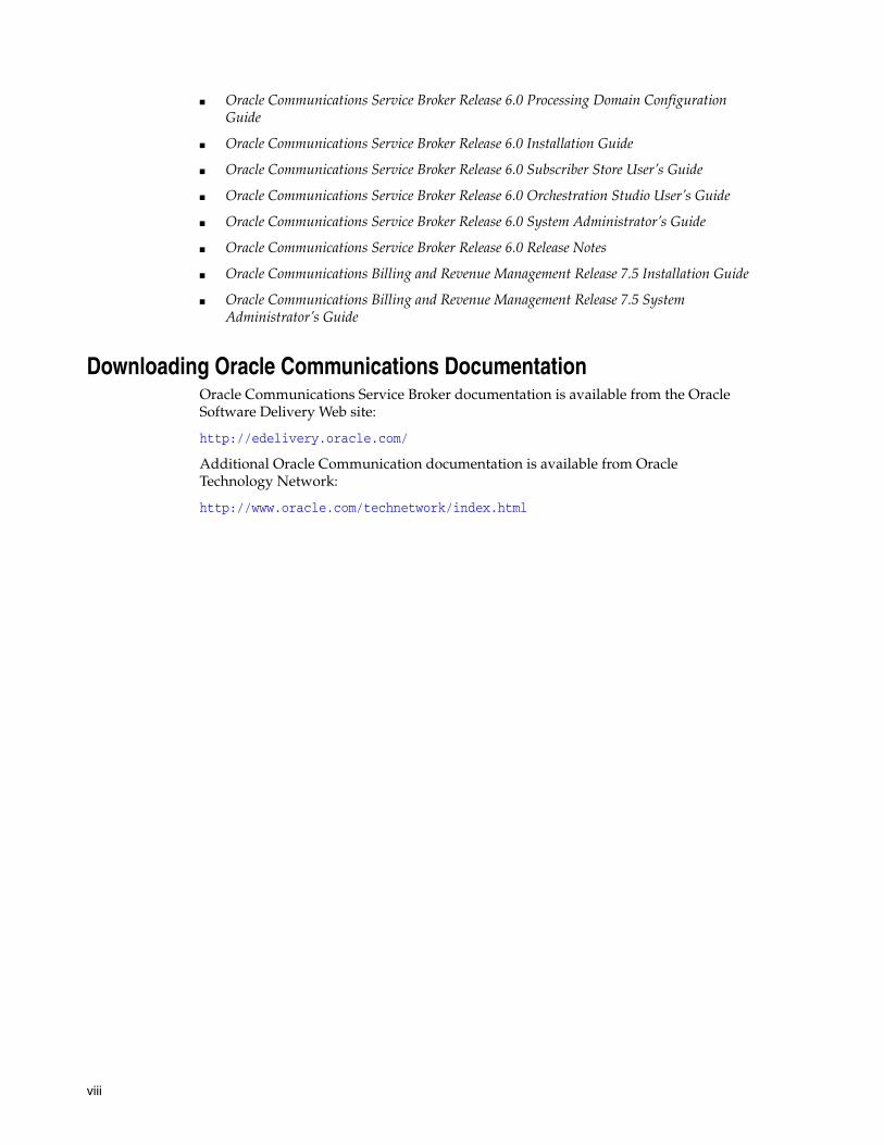
Online Mediation Controller acts as the front end for OCSs, providing connectivity to the network and mediating network protocols, supporting the Diameter and RADIUS protocols and enabling delivery of online charging services for sessions in the network.
When integrated with third party OCSs, it interacts with the OCS through a standard Diameter-based Ro interface, mediating network protocols to Diameter Ro. When integrated with BRM, it interacts with BRM through a Portal Communications Protocol (PCP) interface, mediating network protocols to PCP. This is shown in Figure 1–1.
Figure 1–1 Online Charging Service Delivery to the Network
Complementary Applications
1-2 Online Mediation Controller Implementation Guide
Online Mediation Controller also extends the OCS functionality traditionally associated with balance management and rating, with additional charging reliant features.
The following sections introduce key concepts and features of the Service Broker Online Mediation Controller.
Complementary ApplicationsService Broker provides a Session Abstraction Layer (SAL) interface that you use to implement applications that extend your OCS functionality.
Applications that you implement reside on the session path inside Service Broker, optionally orchestrated and invoked with other external applications, and active during session setup and execution.
Applications can use any session parameter such as called party, call duration and charging information, to run their business logic, and affect session setup and execution synchronously. For example, an application can play an announcement when the subscriber balance goes down below a threshold, asking the subscriber to top up his account.
Applications can also invoke additional asynchronous activities in your system, by publishing events to external entities through a web services API. For example, an application can notify your OSS when a subscriber tops up his account. The session itself is not affected by the notification, but your OSS can trigger asynchronous activities such as sending a notification email to the subscriber.
See Oracle Communications Service Broker SAL Java API Reference, for more information about the SAL interface.
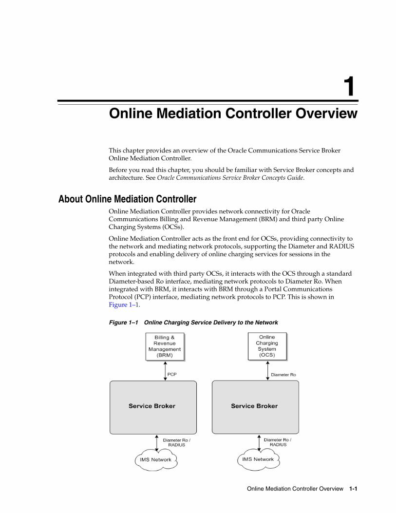
Figure 1–2 shows applications implemented inside a Service Broker domain, that you combine, using service orchestration logic, with online charging services provided by the OCS.
Figure 1–2 Complementary Charging Applications
Subscriber Store
Online Mediation Controller Overview 1-3
Subscriber Store To deliver subscriber-specific services, the Online Mediation Controller maintains its own subscriber profiles. These profiles contain subscriber-specific information that is not traditional stored in the OCS, but required by the Online Mediation Controller's built-in applications.
Subscriber profiles include:
■ The service profile.
■ An orchestration logic that defines how to route subscriber sessions through applications.
■ An extensible subscriber lifecycle that you use to define subscriber states and state transitions.
You can control service delivery for subscribers, specifying which application to invoke and in what order, by basing orchestration logic conditions on the subscriber state.
You extend the subscriber lifecycle by defining the subscriber states your implementation requires. Each state implies a certain set of privileges and prohibitions. For example, you can configure the Online Mediation Controller to charge Active subscribers, or redirect Suspended subscribers to top up their accounts. You can also can publish and consume state transition notifications and actively request state transitions.
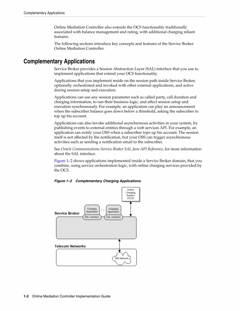
Service Broker includes a web services Subscriber Provisioning API that you use to manage subscriber data in the Subscriber Store. You use this API to add, modify, and remove subscribers from the Subscriber Store, and manage the subscriber lifecycle and states. The Subscriber Provisioning API is accessible by both internal Service Broker components and external systems.
Figure 1–3 shows the Subscriber Store and the Subscriber Provisioning API available for internal Service Broker components and external systems.
Figure 1–3 The Subscriber Store
Event Notification Framework
1-4 Online Mediation Controller Implementation Guide
Event Notification FrameworkComplementary applications use the Event Notification Framework to publish events. The type of event and its timing are application-specific.
Events can be targeted to internal Service Broker components, or to external systems, such as your OSS. External systems use an asynchronous web services Event Notification API to consume these events.
Using the Event Notification Framework, the Online Mediation Controller can be integrated with external Business Intelligence (BI) systems, basing business logic on complementary application events. For example, a parental control application may fire an event when a subscriber reaches a predefined monthly credit threshold, driving further business logic on the OSS side.
OSS applications consuming Online Mediation Controller events may also use those events as triggers to change things in the Online Mediation Controller. OSS applications make changes to the Online Mediation Controller using its web services APIs. For example, if an OSS applications consumes and event noting that a subscriber has reached a predefined monthly credit threshold, then the OSS application can use the Subscriber Provisioning web services API to suspend the subscriber account.
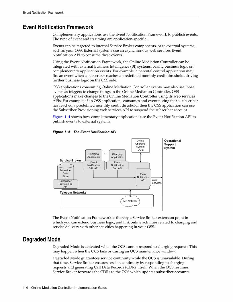
Figure 1–4 shows how complementary applications use the Event Notification API to publish events to external systems.
Figure 1–4 The Event Notification API
The Event Notification Framework is thereby a Service Broker extension point in which you can extend business logic, and link online activities related to charging and service delivery with other activities happening in your OSS.
Degraded ModeDegraded Mode is activated when the OCS cannot respond to charging requests. This may happen when the OCS fails or during an OCS maintenance window.
Degraded Mode guarantees service continuity while the OCS is unavailable. During that time, Service Broker ensures session continuity by responding to charging requests and generating Call Data Records (CDRs) itself. When the OCS resumes, Service Broker forwards the CDRs to the OCS which updates subscriber accounts.
Native Integration with Oracle Communications Billing and Revenue Management
Online Mediation Controller Overview 1-5
User Interaction FrameworkYou use the User Interaction Framework to contact subscribers with charging-related information. The Online Mediation Controller supports these channels for user interaction:
■ Short Message Service (SMS): You can send SMS to subscribers using the Short Message Peer to Peer (SMPP) protocol. For example, you can send an SMS to a subscriber when his account is being activated, after he makes the first use of a service.
■ Announcements: You can use the User Interaction Framework to play mid-call announcements to either the calling party or called party.
Native Integration with Oracle Communications Billing and Revenue Management
While the Online Mediation Controller can be integrated with any OCS through a standard Diameter interface, it is natively integrated with Oracle Communications Billing and Revenue Management (BRM) through the proprietary Portal Communications Protocol (PCP).
Oracle Communications BRM requires Service Broker to act as its front-end, providing network connectivity through Diameter Ro and RADIUS.
Service Broker release 6.0 is aligned with Oracle Communications BRM release 7.5.
This document provides general instructions for integrating the Online Mediation Controller with any OCS, and specific information for integrating with BRM.
Online Mediation Controller includes a number of built-in sample applications to support the combined Service Broker and Oracle Communications BRM solution. For example, the zone-based charging application can identify roaming subscribers, and use the Short Message Service (SMS) to alert them that different rates apply to roaming calls.
When integrated with Oracle Communications BRM, the Online Mediation Controller also mediates RADIUS to PCP, providing complete support for session authentication, authorization and accounting.

Native Integration with Oracle Communications Billing and Revenue Management
1-6 Online Mediation Controller Implementation Guide
2
Setting Up the Subscriber Store 2-1
2Setting Up the Subscriber Store
This chapter describes how to set up the Oracle Communications Service Broker Subscriber Store.
About the Subscriber StoreThe Online Mediation Controller provides a way to deliver online charging and related services to subscribers. It integrates with an OCS for online charging services and includes built-in applications that extend the OCS functionality. For example, the Balance Manager application enables subscribers to check the balance of and add value to their accounts.
To deliver subscriber-specific services, Service Broker maintains its own profile of subscribers. Subscriber profile contains subscriber-specific information required by the Service Broker’s built-in applications. For example, the Balance Manager applications requires subscriber language to know in which language to compose SMS messages that it sends to the subscriber. The subscriber profile is supplemental to the subscriber data maintained the OCS.
The subscriber profile also includes an orchestration logic defining how to route subscriber sessions through applications. Orchestration logic in the subscriber profile is stored in an iFC format. Oracle recommends that you use the Service Broker Orchestration Studio to graphically create orchestration logic, and use the iFC formatted source of the orchestration logic to provision a subscriber profile in the Subscriber Store.
While conditions in the orchestration logic are mostly based on session information, they can also depend on the following subscriber data available in the Subscriber Store:
■ Degraded Mode state. See "Using Degraded Mode".
■ Lifecycle state. See "Using Subscriber Lifecycles" in Oracle Communications Service Broker Subscriber Store Users’s Guide.
For example, you can configure the orchestration logic to route a session to the OCS only if the subscriber state is Active.
In the Online Mediation Controller you must configure the OE to use the Subscriber store as the source for subscriber profiles.
WARNING: In the Online Mediation Controller, you can only use the Subscriber Store as the source for subscriber profiles. You cannot use the Local Subscriber Server (LSS) to store orchestration profiles.

Configuration Workflow
2-2 Online Mediation Controller Implementation Guide
The persistent mechanism for Subscriber Store can be a database or a file-based storage. The data store is set up by default, as part of the Service Broker post installation step. See "Configuring Data Storage" in the chapter "Post Installation Tasks" in Oracle Communications Service Broker Installation Guide.
You populate the Subscriber store using the Subscriber Provisioning Web Services API.
The Service Broker Subscriber Store is described in Oracle Communications Service Broker Subscriber Store User’s Guide.
Configuration WorkflowTo configure the Subscriber Store:
1. Set up the Subscriber Store and enable the Subscriber Provisioning API. See "Configuring the Subscriber Provisioning Services" in Oracle Communications Service Broker Subscriber Store User’s Guide.
2. Populate the Subscriber Store with subscriber profiles. See "Using the Subscriber Provisioning API" and "Subscriber Provisioning API Reference" in Oracle Communications Service Broker Subscriber Store User’s Guide.
3. Configure the OE to use the Subscriber Store as a source of subscriber profiles.
Configure the OE as described in "Configuring the Orchestration Engine" in Oracle Communications Service Broker Processing Domain Configuration Guide. Use the following configuration data, specifically:
1. In the General tab, in the Subscriber Profile Receiver list, select OlpCustomInfoReceiver.
2. In the Custom OLP tab, in the Custom OPR Name field, enter UP OPR.

3
Setting Up Orchestrated Charging Mediation 3-1
3Setting Up Orchestrated Charging Mediation
Oracle Communications Service Broker online mediation Controller provides a way for an Online Charging System (OCS) to charge subscribers and accounts, for services that they use in the IMS network.
This chapter describes how you set up and configure orchestrated charging mediation.
About Orchestrated Charging MediationOCS allows communications service providers to charge their subscribers, in real time, based on service usage. An OCS authenticates subscribers and maintains accounts that subscribers use to pay for services that they use. It can influence, in real time, the service rendered to a subscriber and therefore needs a direct interaction with the communications network.
Service Broker provides an OCS with a front-end to the network. Service Broker communicates with the network through its native protocols, exposing one unified interface to the OCS.
The unified interface is based on either a standard Diameter Ro or PCP. You can use any of the two interfaces, depending on the type of OCS you are using. For integration with Oracle Communications Billing and Revenue Management (BRM) the PCP interface is used.
Figure 3–1 shows the application-facing interworking modules and network-facing interworking modules that you need to deploy and configure to apply an online charging service.
You use:
■ R-IM-OCF-Ro, to charge services in the IMS network
■ Depending on the type of OCS in your system, use one of the following:
■ OCS supporting a standard Diameter Ro interface: IM-OCF-Ro
■ Oracle Communications BRM: IM-OCF-PCP
Configuration Workflow
3-2 Online Mediation Controller Implementation Guide
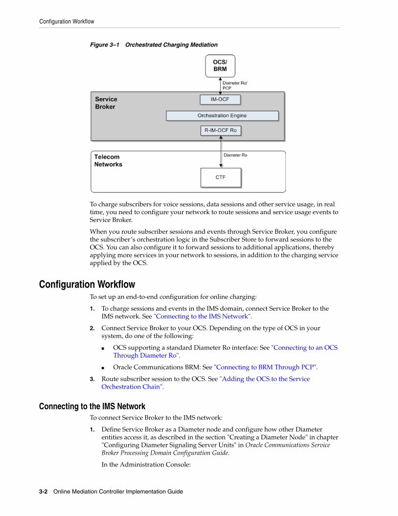
Figure 3–1 Orchestrated Charging Mediation
To charge subscribers for voice sessions, data sessions and other service usage, in real time, you need to configure your network to route sessions and service usage events to Service Broker.
When you route subscriber sessions and events through Service Broker, you configure the subscriber’s orchestration logic in the Subscriber Store to forward sessions to the OCS. You can also configure it to forward sessions to additional applications, thereby applying more services in your network to sessions, in addition to the charging service applied by the OCS.
Configuration WorkflowTo set up an end-to-end configuration for online charging:
1. To charge sessions and events in the IMS domain, connect Service Broker to the IMS network. See "Connecting to the IMS Network".
2. Connect Service Broker to your OCS. Depending on the type of OCS in your system, do one of the following:
■ OCS supporting a standard Diameter Ro interface: See "Connecting to an OCS Through Diameter Ro".
■ Oracle Communications BRM: See "Connecting to BRM Through PCP".
3. Route subscriber session to the OCS. See "Adding the OCS to the Service Orchestration Chain".
Connecting to the IMS NetworkTo connect Service Broker to the IMS network:
1. Define Service Broker as a Diameter node and configure how other Diameter entities access it, as described in the section "Creating a Diameter Node" in chapter "Configuring Diameter Signaling Server Units" in Oracle Communications Service Broker Processing Domain Configuration Guide.
In the Administration Console:

Configuration Workflow
Setting Up Orchestrated Charging Mediation 3-3
a. In the navigation tree, expand the OCSB node, and then the Signaling Tier node.
b. Select the SSU Diameter node.
c. In the DIAMETER tab, select the Diameter Configuration tab.
d. You can either use the default node or create a new node by clicking the Plus (+) icon below the Node tree. The General tab appears.
e. In the Name field, enter a unique name for the Diameter node.
f. In the Realm field, enter the realm name that other Diameter nodes use to access Service Broker.
g. In the Port field, enter the port number that signaling servers use to listen to Diameter traffic.
h. Leave the Address, Host and Target fields blank to apply the configuration to all signaling servers in the Signaling Domain and have them all provide a Diameter network channel on the same port.
2. Deploy the R-IM-OCF-Ro module as described in "Managing Interworking Modules" in Oracle Communications Service Broker Processing Domain Configuration Guide.
In the Administration Console:
a. In the navigation tree, expand the OCSB node.
b. Expand the Processing Tier node, and then the Interworking Modules node.
c. Click IM Management.
d. In the IM Management tab, click the New button. The New dialog box appears.
e. From the Type list, select RIMOCF.
f. In the Name field, enter a module instance name. For example, rimocfro_instance.
g. Click the OK button.
3. Configure the R-IM-OCF-Ro module as described in "Configuring R-IM-OCF-Ro" in Oracle Communications Service Broker Processing Domain Configuration Guide.
4. Configure the Diameter SSU to accept incoming Diameter requests as described in "Configuring the Diameter SSU" in Oracle Communications Service Broker Signaling Domain Configuration Guide.
Specifically, add a new incoming routing rule to route incoming Ro requests to the R-IM-OCF module that you created in step 2.
In the Administration Console:
a. In the navigation tree, expand the OCSB node, and then the Signaling Tier node.
Note: If you run multiple signaling servers on the same physical machine, you have to define each signaling server as a different Diameter node which listens on a different port. Otherwise, if the Diameter SSU running on all signaling servers uses the same port, then the ports will collide.
Configuration Workflow
3-4 Online Mediation Controller Implementation Guide
b. Select the SSU Diameter node.
c. In the SSU Diameter tab, select the Routing tab, and then the Incoming Routing Rules tab.
d. Click the New button. The New dialog box appears.
e. In the Name field, enter a name for the new routing rule.
f. In the Priority field, leave the default value.
g. In the Module Instance field, enter ssu:r-im-ocf-ro-module-name.RIMOCF@domain-id, where r-im-ocf-ro-module-name is the name you gave to the R-IM-OCF-Ro module in step 2, and domain-id is the name of the Processing Domain where you deployed the R-IM-OCF-Ro.
If your deployment includes only one Processing Domain, then set domain-id to ocsb. For example, rimocfro_instance.RIMOCF@ocsb.
h. Click the OK button.
Specify the criteria that Ro requests have to meet so that the Diameter SSU forward them to R-IM-OCF-Ro:
a. In the SSU Diameter tab, select the Routing tab, and then the Incoming Routing Criteria tab.
b. From the Parent list, select the name of the incoming routing rule that you have just created. You will now define the criteria to apply this rule.
c. Click the New button. The New dialog box appears.
d. In the Name field, enter a name for the new criteria.
In the Attribute field, select the AVP whose value the Diameter SSU checks in incoming request.
In the Value field, enter the value that the AVP should match for the Diameter SSU to route incoming requests into Service Broker.
e. Click the OK button.
5. Activate the R-IM-OCF-Ro module that you deployed and configured in steps 2 and 3.
In the Administration Console:
a. In the navigation tree, expand the OCSB node.
b. Expand the Processing Tier node and then the Interworking Modules node.
c. Click on IM Management.
d. In the IM Management tab, select the R-IM-OCF-Ro module in the table.
e. Click the Activate button.
Connecting to an OCS Through Diameter RoTo connect Service Broker to an OCS:
1. In the Diameter SSU, configure the OCS instances as Diameter peers, as described in "Configuring the Diameter SSU" in Oracle Communications Service Broker Signaling Domain Configuration Guide.
At a minimum, it is recommended to establish connection with two peers per realm.
Configuration Workflow
Setting Up Orchestrated Charging Mediation 3-5
In the Administration Console:
a. In the navigation tree, expand the OCSB node, and then the Signaling Tier node.
b. Select the SSU Diameter node.
c. In the DIAMETER tab, select the Diameter Configuration tab and then the Peers tab.
d. Click the New button (+). The New Data dialog appears.
e. In the Address field, enter the IP address or DNS name of the peer.
f. In the Host field, enter the Destination-Host AVP value identifying the peer. You will refer this value later when configuring outgoing Diameter routes.
g. In the Port field, enter the listen port number of the peer node
h. In the Protocol field, enter the protocol used to communicate with the peer: tcp or sctp.
i. Check the Watchdog checkbox if the peer supports the Diameter Tw watchdog timer interval.
j. Click the OK button.
k. Repeat steps d through j for each OCS instance in your system.
2. In the Diameter SSU, define the OCS as a Diameter destination. You can define two or more destinations having different Destination-Host AVPs, that share the same alias, thereby adding a level of redundancy, treating all destinations as one logical destination, and balancing the load among destinations.
a. In the navigation tree, expand the OCSB node, and then the Signaling Tier node.
b. Select the SSU Diameter node.
c. In the SSU Diameter tab, select the Outbound Destinations tab.
d. Click the New button. The New dialog box appears.
e. In the Name field, enter a name for the OCS.
f. In the Alias field, enter an alias that you want to assign to the destination OCS. You can enter the same alias later when you define more destination OCSs, to have a number of destination OCSs share load.
g. In the Destination Host and Destination Realm fields, enter the Destination Host and Destination Realm of the peers running the OCS. Use the Destination Host of the peers you defined in step 1.
h. Click the OK button.
i. Repeat steps d through h for each additional destination OCS that you want to configure.
3. Deploy the IM-OCF-Ro module as described in "Managing Interworking Modules" in Oracle Communications Service Broker Processing Domain Configuration Guide.
In the Administration Console:
a. In the navigation tree, expand the OCSB node.
b. Expand the Processing Tier node, and then the Interworking Modules node.
Configuration Workflow
3-6 Online Mediation Controller Implementation Guide
c. Click on IM Management.
d. In the IM Management tab, click New.
e. From the Type list, select IMOCF.
f. In the Name field, enter a module instance name. For example, imocfro_instance.
g. Click the OK button.
4. Configure the IM-OCF-Ro instance as described in "Configuring IM-OCF-Ro" in Oracle Communications Service Broker Processing Domain Configuration Guide.
Specifically, you need to define the destination OCS that the IM-OCF-Ro instance communicates with. You can either specify Destination-Host and Destination-Realm AVPs, or you can use the alias of a destination that you defined in step 1.
In the Administration Console:
a. In the navigation tree, expand the OCSB node.
b. Expand the Processing Tier node, and then the Interworking Modules node.
c. Click on IM Management.
d. Select the IM-OCF-Ro module node.
e. In the Configuration tab, select the Diameter Credit Control Application tab, and then the AVPs tab.
f. In the Destination-Realm AVP field, enter the alias that you assigned to the destination OCS that you defined in step 1. Alternatively, in the Destination-Realm AVP and in the Destination-Host AVP fields, enter the values that the IM-OCF-Ro must set in the Destination-Host and Destination-Realm AVPs of outgoing Diameter request, in order to route requests to the destination OCS.
g. Click the Apply button.
5. Activate the IM-OCF-Ro module that you deployed and configured in steps 3 and 4.
In the Administration Console:
a. In the navigation tree, expand the OCSB node.
b. Expand the Processing Tier node and then the Interworking Modules node.
c. Click on IM Management.
d. In the IM Management tab, select the IM-OCF-Ro module in the table.
e. Click the Activate button.
Connecting to BRM Through PCPTo connect Service Broker to Oracle Communications BRM:
1. Create BRM connection pools in the PCP SSU, as described in "Defining Connection Pools" in the chapter "Configuring the PCP Signaling Server Unit" in Oracle Communications Service Broker Signaling Domain Configuration Guide.
See also "About Connection Pooling" in Oracle Communications Billing and Revenue Management System Administrator’s Guide.
Configuration Workflow
Setting Up Orchestrated Charging Mediation 3-7
2. Secure the BRM connection pools that you created in step 1, as described in "Securing Connection Pools" in the chapter "Configuring the PCP Signaling Server Unit" in Oracle Communications Service Broker Signaling Domain Configuration Guide.
In the Administration Console:
a. In the navigation tree, expand the OCSB node, and then the Signaling Tier node.
b. Select the SSU PCP node.
c. In the PCP tab, select the Credential Store tab.
d. In the Password area, in the Key field, enter the ID of the connection pool that you want to secure. This should be the Pool ID that you assigned to the connection pool when you created the connection pool in step 1.
e. In the Password area, in the Password field, enter the password of the Oracle Communications BRM client application account used by the connection pool to access the BRM. This should be the password of the account that you configured in the BRM CM Login ID field when you initially defined the connection pool.
f. In the Password area, uncheck the one-way checkbox.
g. In the Password area, click the Set Password button.
h. Repeat steps d through f for each connection pool that you want to secure.
3. Define destination BRM applications, as described in "Defining PCP Network Entities" in the chapter "Configuring the PCP Signaling Server Unit" in Oracle Communications Service Broker Signaling Domain Configuration Guide.
4. Deploy the IM-OCF-PCP module as described in "Managing Interworking Modules" in Oracle Communications Service Broker Processing Domain Configuration Guide.
In the Administration Console:
a. In the navigation tree, expand the OCSB node.
b. Expand the Processing Tier node, and then the Interworking Modules node.
c. Click on IM Management.
d. In the IM Management tab, click New.
e. From the Type list, select IMOCFPCP.
f. In the Name field, enter a module instance name. For example, imocfpcp_instance.
g. Click the OK button.
5. Configure the IM-OCF-PCP instance as described in "Configuring IM-OCF PCP" in Oracle Communications Service Broker Processing Domain Configuration Guide.
Specifically, you need to define the destination OCS that the IM-OCF-PCP module communicates with. You can either specify Destination-Host and Destination-Realm AVPs, or you can use an alias of a destination that you defined in step 1.
In the Administration Console:
a. In the navigation tree, expand the OCSB node.
b. Expand the Processing Tier node, and then the Interworking Modules node.
Setting Orchestrated Charging Mediation in Degraded Mode
3-8 Online Mediation Controller Implementation Guide
c. Click on IM Management.
d. Select the IM-OCF-PCP module node.
e. In the Configuration tab, select the Diameter Credit Control Application tab, and then the AVPs tab.
f. In the Destination-Realm AVP field, enter the alias that you assigned to the destination BRM connection pool that you defined in step 1. Alternatively, in the Destination-Realm AVP and in the Destination-Host AVP fields, enter the values that the IM-OCF-PCP must set in the Destination-Host and Destination-Realm AVPs of outgoing Diameter request, in order to route requests to the destination BRM.
g. Click the Apply button.
6. Activate the IM-OCF-PCP instance that you deployed and configured in steps 4 and 5.
In the Administration Console:
a. In the navigation tree, expand the OCSB node.
b. Expand the Processing Tier node and then the Interworking Modules node.
c. Click on IM Management.
d. In the IM Management tab, select the IM-OCF-PCP module in the table.
e. Click the Activate button.
Adding the OCS to the Service Orchestration ChainTo route subscriber sessions to the OCS:
1. Depending on your implementation, create an appropriate orchestration logic that routes network sessions through the OCS in your system. Use the Orchestration Studio to create the orchestration logic. See Oracle Communications Service Broker Orchestration Studio User’s Guide.
2. Assign the orchestration logic you created in step 1 to subscribers. Use the Subscriber Provisioning API to provision the iFC source of the orchestration logic in subscribers’ IfcProfileData. See "Using the Subscriber Provisioning API" in Oracle Communication Service Broker Subscriber Store User’s Guide, for more information.
Setting Orchestrated Charging Mediation in Degraded ModeFor information on setting up orchestrated mediation in Degraded Mode, see the discussion about the orchestrated mediation in "Using Degraded Mode".
4
Setting Up Passthrough Charging Mediation to BRM 4-1
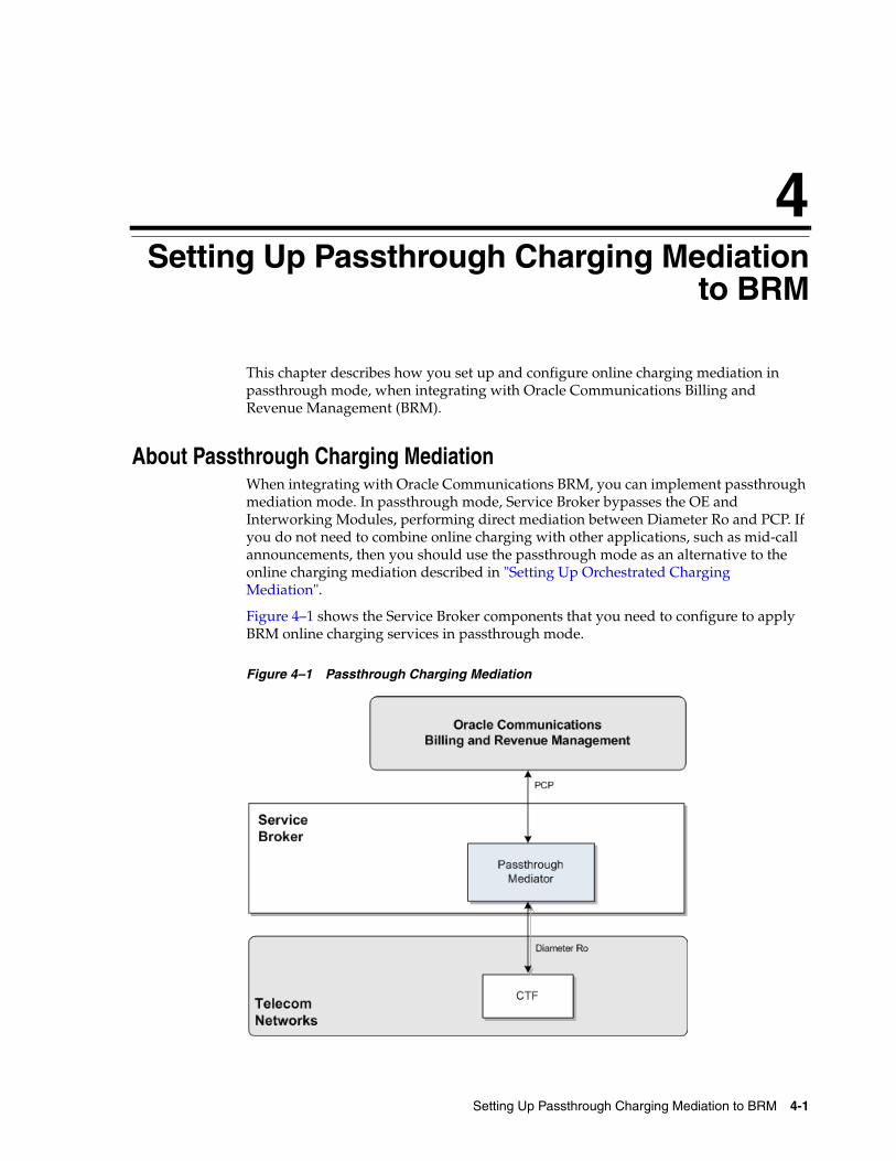
4Setting Up Passthrough Charging Mediationto BRM
This chapter describes how you set up and configure online charging mediation in passthrough mode, when integrating with Oracle Communications Billing and Revenue Management (BRM).
About Passthrough Charging MediationWhen integrating with Oracle Communications BRM, you can implement passthrough mediation mode. In passthrough mode, Service Broker bypasses the OE and Interworking Modules, performing direct mediation between Diameter Ro and PCP. If you do not need to combine online charging with other applications, such as mid-call announcements, then you should use the passthrough mode as an alternative to the online charging mediation described in "Setting Up Orchestrated Charging Mediation".
Figure 4–1 shows the Service Broker components that you need to configure to apply BRM online charging services in passthrough mode.
Figure 4–1 Passthrough Charging Mediation

Configuring Passthrough Mode
4-2 Online Mediation Controller Implementation Guide
Configuring Passthrough ModeTo configure passthrough mode:
1. Configure Service Broker as a Diameter node. See "Configuring Service Broker as a Diameter Node".
2. Create BRM connection pools. See "Creating BRM Connection Pools".
3. Secure the BRM connection pools that you created in step 2. See "Securing BRM Connection Pools".
4. Configure destination BRM applications. See "Configuring Destination BRM Applications".
5. Configure the passthrough mediator. See "Configuring the Passthrough Mediator".
Configuring Service Broker as a Diameter NodeThis section describes how to configure Service Broker as a Diameter node and define how other Diameter entities access it. For details, see the information on creating a Diameter node in "Configuring Diameter Signaling Server Units" in Oracle Communications Service Broker Processing Domain Configuration Guide.
In the Administration Console:
1. In the navigation tree, expand the OCSB node, and then the Signaling Tier node.
2. Select the SSU Diameter node.
3. In the DIAMETER tab, select the Diameter Configuration tab.
4. You can either use the default node or create a new node by clicking the Plus (+) icon below the Node tree. The General tab appears.
5. In the Name field, enter a unique name for the Diameter node.
6. In the Realm field, enter the realm name that other Diameter entities use to access Service Broker.
7. In the Port field, enter the port number that signaling servers use to listen to Diameter traffic.
8. Leave the Address, Host and Target fields blank to apply the configuration to all signaling servers in the Signaling Domain and have them all provide a Diameter network channel on the same port.
Creating BRM Connection PoolsCreate BRM connection pools in the PCP SSU. For more information, see PCP connection pool information in "Configuring the PCP Signaling Server Unit" in Oracle Communications Service Broker Signaling Domain Configuration Guide.
See also "About Connection Pooling" in Oracle Communications Billing and Revenue Management System Administrator’s Guide.
Note: If you run multiple signaling servers on the same physical machine, you have to define each signaling server as a different Diameter node which listens on a different port. Otherwise, if the Diameter SSU running on all signaling servers will use the same port, then the ports will collide.
Configuring Passthrough Mode
Setting Up Passthrough Charging Mediation to BRM 4-3
The passthrough mediator will later route outgoing PCP requests to BRM applications through the connection pools that you defined. See "Routing Outgoing PCP Requests to BRM Applications".
Securing BRM Connection PoolsSecure the BRM connection pools, as described in "Securing Connection Pools" in the chapter "Configuring the PCP Signaling Server Unit" in Oracle Communications Service Broker Signaling Domain Configuration Guide.
In the Administration Console:
1. In the navigation tree, expand the OCSB node, and then the Signaling Tier node.
2. Select the SSU PCP node.
3. In the PCP tab, select the Credential Store tab.
4. In the Password area, enter the ID of the connection pool that you want to secure, in the Key field. This should be the Pool ID that you assigned to the connection pool when you created the connection pool.
5. In the Password area, enter the password of the BRM client application account used by the connection pool to access the BRM, in the Password field. This should be the password of the account that you configured in the BRM CM Login ID field when you initially defined the connection pool.
6. In the Password area, uncheck the one-way checkbox.
7. In the Password area, click the Set Password button.
8. Repeat steps 4 through 7 for each connection pool that you want to secure.
Configuring Destination BRM ApplicationsDefine destination BRM applications. For more information, see PCP network entities information, in "Configuring the PCP Signaling Server Unit" in Oracle Communications Service Broker Signaling Domain Configuration Guide.
Configuring the Passthrough MediatorThis section describes how to configure the passthrough mediator using the Service Broker Administration Console.
To access the passthrough mediator configuration screen:
1. In the domain navigation pane, expand OCSB.
2. Expand Processing Tier.
3. Expand Passthrough Mediation.
In the passthrough mediation:
1. Route incoming Diameter request through the passthrough mediator. See "Routing Incoming Diameter Requests Through the Passthrough Mediator".
2. Configure general Ro to PCP mediation parameters. See "Configuring General Ro to PCP Mediation Parameters".
3. Route outgoing PCP requests to BRM applications. See "Routing Outgoing PCP Requests to BRM Applications".
4. Configure service types. See "Configuring Service Type Parameters".

Configuring Passthrough Mode
4-4 Online Mediation Controller Implementation Guide
Routing Incoming Diameter Requests Through the Passthrough MediatorIncoming Diameter requests will be routed through the passthrough mediator if their Origin-Realm AVP contains a specific value that you configure.
To specify the value of the Origin-Realm AVP:
1. In the navigation pane, select the Routing node.
2. In the Origin Realm field, enter the value required in the Origin-Realm AVP to have requests routed to the passthrough mediator.
3. Click the Apply button.
Configuring General Ro to PCP Mediation ParametersTo configure general Ro to PCP mediation parameters:
1. In the navigation pane, select the Ro PCP Mediation node.
2. Select the General tab.
3. Configure the parameters described in Table 4–1
Routing Outgoing PCP Requests to BRM Applications The passthrough mediator routes outgoing PCP requests through connection pools that you create. See "Creating BRM Connection Pools".
By default, the passthrough mediator routes requests through all connection pools in a round-robin fashion. However, you can also enable a resolution mechanism that routes requests based on the value of an AVP inside the request. In this case, the value of the AVP is resolved into a connection pool; the value of the AVP needs to match the alias of a destination BRM application, that is the alias of a PCP network entity configured in the PCP SSU.
To configure how the passthrough mediator routes PCP requests through connection pools:
1. In the navigation pane, select the Ro PCP Mediation node.
2. Select the SSU PCP Alias Resolver tab.
Table 4–1 Ro to PCP Mediation General Parameters
Name Type Description
Client Program Name String The name representing the passthrough mediator as a BRM client application when accessing BRM.
Default value: Matrix
Object Type String Always set this value to gsm.
Default Opcode Timeout Integer The time to allow for a charging requests to execute before it is considered to have timed out. Given in seconds.
Reservation Expiration Time
Integer The time BRM applications keeps reservation objects before they release them. Given in milliseconds.
Default value: 86400000 (24 hours)
See "About Creating Reservations" in the chapter "Reserving Resources for Concurrent Network Sessions" in Oracle Communications Billing and Revenue Management Configuring and Collecting Payments.
Extending Mediation Support
Setting Up Passthrough Charging Mediation to BRM 4-5
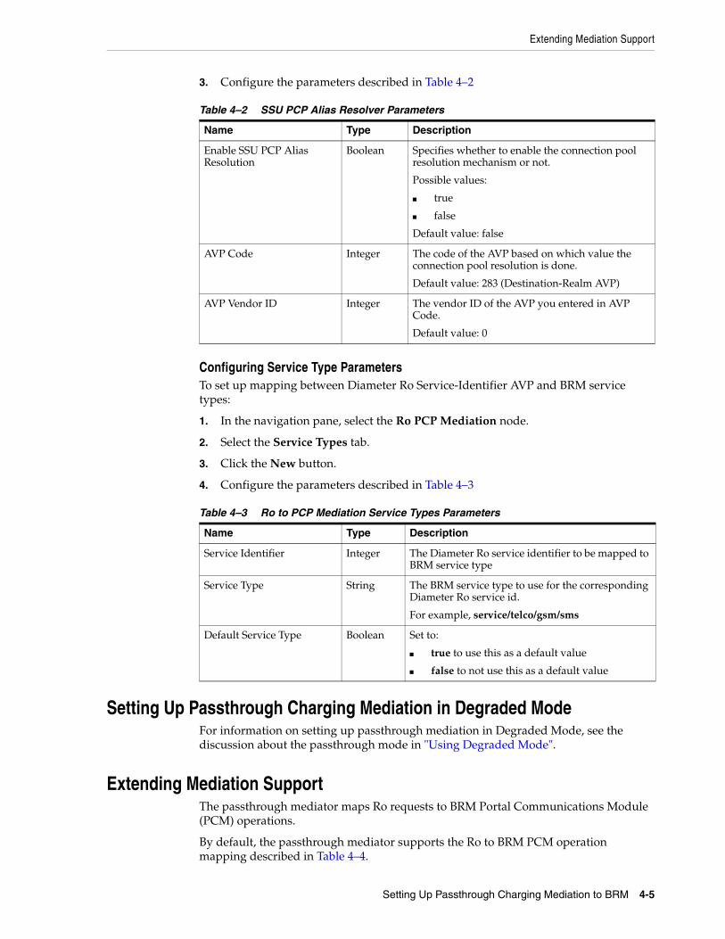
3. Configure the parameters described in Table 4–2
Configuring Service Type ParametersTo set up mapping between Diameter Ro Service-Identifier AVP and BRM service types:
1. In the navigation pane, select the Ro PCP Mediation node.
2. Select the Service Types tab.
3. Click the New button.
4. Configure the parameters described in Table 4–3
Setting Up Passthrough Charging Mediation in Degraded ModeFor information on setting up passthrough mediation in Degraded Mode, see the discussion about the passthrough mode in "Using Degraded Mode".
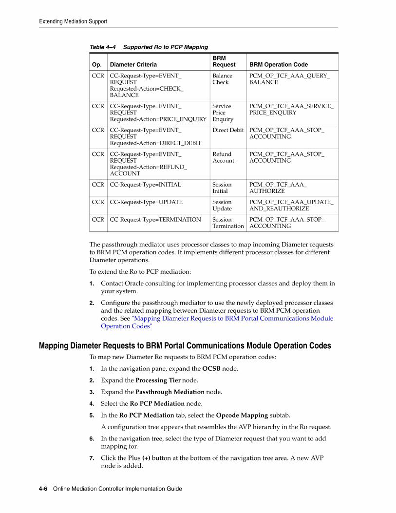
Extending Mediation SupportThe passthrough mediator maps Ro requests to BRM Portal Communications Module (PCM) operations.
By default, the passthrough mediator supports the Ro to BRM PCM operation mapping described in Table 4–4.
Table 4–2 SSU PCP Alias Resolver Parameters
Name Type Description
Enable SSU PCP Alias Resolution
Boolean Specifies whether to enable the connection pool resolution mechanism or not.
Possible values:
■ true
■ false
Default value: false
AVP Code Integer The code of the AVP based on which value the connection pool resolution is done.
Default value: 283 (Destination-Realm AVP)
AVP Vendor ID Integer The vendor ID of the AVP you entered in AVP Code.
Default value: 0
Table 4–3 Ro to PCP Mediation Service Types Parameters
Name Type Description
Service Identifier Integer The Diameter Ro service identifier to be mapped to BRM service type
Service Type String The BRM service type to use for the corresponding Diameter Ro service id.
For example, service/telco/gsm/sms
Default Service Type Boolean Set to:
■ true to use this as a default value
■ false to not use this as a default value
Extending Mediation Support
4-6 Online Mediation Controller Implementation Guide
The passthrough mediator uses processor classes to map incoming Diameter requests to BRM PCM operation codes. It implements different processor classes for different Diameter operations.
To extend the Ro to PCP mediation:
1. Contact Oracle consulting for implementing processor classes and deploy them in your system.
2. Configure the passthrough mediator to use the newly deployed processor classes and the related mapping between Diameter requests to BRM PCM operation codes. See "Mapping Diameter Requests to BRM Portal Communications Module Operation Codes"
Mapping Diameter Requests to BRM Portal Communications Module Operation CodesTo map new Diameter Ro requests to BRM PCM operation codes:
1. In the navigation pane, expand the OCSB node.
2. Expand the Processing Tier node.
3. Expand the Passthrough Mediation node.
4. Select the Ro PCP Mediation node.
5. In the Ro PCP Mediation tab, select the Opcode Mapping subtab.
A configuration tree appears that resembles the AVP hierarchy in the Ro request.
6. In the navigation tree, select the type of Diameter request that you want to add mapping for.
7. Click the Plus (+) button at the bottom of the navigation tree area. A new AVP node is added.
Table 4–4 Supported Ro to PCP Mapping
Op. Diameter CriteriaBRM Request BRM Operation Code
CCR CC-Request-Type=EVENT_REQUEST Requested-Action=CHECK_BALANCE
Balance Check
PCM_OP_TCF_AAA_QUERY_BALANCE
CCR CC-Request-Type=EVENT_REQUEST Requested-Action=PRICE_ENQUIRY
Service Price Enquiry
PCM_OP_TCF_AAA_SERVICE_PRICE_ENQUIRY
CCR CC-Request-Type=EVENT_REQUEST Requested-Action=DIRECT_DEBIT
Direct Debit PCM_OP_TCF_AAA_STOP_ACCOUNTING
CCR CC-Request-Type=EVENT_REQUEST Requested-Action=REFUND_ACCOUNT
Refund Account
PCM_OP_TCF_AAA_STOP_ACCOUNTING
CCR CC-Request-Type=INITIAL Session Initial
PCM_OP_TCF_AAA_AUTHORIZE
CCR CC-Request-Type=UPDATE Session Update
PCM_OP_TCF_AAA_UPDATE_AND_REAUTHORIZE
CCR CC-Request-Type=TERMINATION Session Termination
PCM_OP_TCF_AAA_STOP_ACCOUNTING
Extending Mediation Support
Setting Up Passthrough Charging Mediation to BRM 4-7
8. In the AVP tab in the right hand pane, enter the following fields for the AVP that you want to map:
■ AVP Code
■ AVP Vendor ID
■ AVP Value
9. Click the Add Opcode Mapping button. The Mapping tab appears.
10. In the Mapping tab, set the following fields as described:
■ In the Processor Class field, enter name of the name of the processor class implementing the mapping that you are currently configuring.
■ In the Opcode ID and Opcode Flag fields, enter the BRM operation code and operation flag.
■ In the Opcode Timeout field, enter the time to allow for the BRM operation to execute before it is considered to have timed out. Given in milliseconds.

Extending Mediation Support
4-8 Online Mediation Controller Implementation Guide
5
Using Degraded Mode 5-1
5Using Degraded Mode
This chapter describes how to enable and use degraded mode operation in the Oracle Communications Service Broker.
About Degraded ModeIn an Online Mediation Controller deployment, Service Broker relies on an external online charging system (OCS) to make service authorization decisions and apply activity charges to subscriber accounts.
As network-connected components, Service Broker and the OCS depend upon the proper functioning of the network between them. Network disruption or a hardware failure may affect the ability of users to access network services.
Degraded mode is a Service Broker operating mode that ensures service continuity for end users if the OCS becomes unavailable. When degraded mode is enabled, Service Broker monitors the health of the external OCS. If the OCS becomes unavailable for any reason, Service Broker temporarily assumes the functions of the external OCS.
While acting on behalf of the external OCS, Service Broker applies a default authorization decision to incoming service requests. It also records user activity information, which it stores locally in the form of charging data records (CDRs).
Service Broker uses the CDRs to replay the charging requests to the OCS later, when it is available again. From the point-of-view of the external OCS, degraded mode operation is transparent. The external OCS is unaware whether a particular accounting or charging request reflects current activity or is the result of CDR replay. Accordingly, the OCS requires no special configuration to support degraded mode.
About Degraded Mode TriggersWhen degraded mode is enabled, Service Broker monitors the availability of the external OCS and automatically assumes the functions of the OCS in response to these events:
■ The OCS fails to acknowledge or reply to a request during an active session.
■ The OCS does not reply to a heartbeat check.
When degraded mode is triggered by a failure during an active session, only the affected session is transferred to degraded mode. The active session is processed in degraded mode until completed. Other active sessions and new sessions (except those associated with the same user that is being handled in degraded mode) continue to be handled by the external OCS.
About Degraded Mode
5-2 Online Mediation Controller Implementation Guide
If in-order CDR replay is enabled, any new sessions associated with a user who is already in degraded mode are handled in degraded mode as well. This ensures that the activities recorded in all CDRs for that user are replayed in the order in which they occurred, even if that user is accessing the network from different devices.
If degraded mode is triggered by a heartbeat check failure, Service Broker moves all active sessions to degraded mode and handles new sessions in degraded mode. Meanwhile, Service Broker continues to monitor the availability of the external OCS. When the OCS becomes available again, Service Broker resumes using it for new sessions. Existing sessions continue to be processed in degraded mode until completed.
You can also trigger degraded mode manually. This is useful when you know in advance of system downtime, for example, for planned maintenance.
About Configuring Degraded ModeBy default, degraded mode is disabled. That is, Service Broker does not monitor the availability of a remote OCS or automatically assume the OCS role if it becomes unavailable.
To enable degraded mode, you need to configure degraded mode operation settings, along with the settings related to degraded mode in the SSU and IMs that interact with the external OCS, as described in this chapter.
Degraded mode operation relies upon the Subscriber Store (the Service Broker repository of end user information) for certain capabilities. For example, the Subscriber Store enables Service Broker to correlate multiple sessions initiated on different devices to a single actual end user. This allows Service Broker to replay all CDRs associated with a given end user in order, even for sessions that were originated on different devices.
Also, for degraded mode to work properly with orchestrated mediation, Service Broker must be configured to retrieve iFCs from the Subscriber Store. Degraded mode does not work if Service Broker retrieves iFCs using the LSS mechanism. See Oracle Communications Service Broker Subscriber Data User’s Guide for information on how to set up the Subscriber Store.
Degraded mode can be used with orchestrated or non-orchestrated charging mediation deployments. In non-orchestrated (passthrough) mediation, incoming Diameter Ro requests bypass orchestration and other mediation processing steps normally applied in the Processing Tier.
The general steps for configuring degraded mode for passthrough mediation are:
1. Configure CDR persistence.
2. Configure an outbound route to the local OCS in the Diameter SSU of the Signaling Domain.
3. Configure local OCS properties, the settings applicable to the internal Service Broker component that performs the function of the external OCS.
4. Configure the default client authentication decision when Service Broker is acting on behalf of the external OCS.
5. Configure CDR replay settings.
6. Configure external OCS monitoring.
7. Configure service unit counters.

Configuring the Signaling Tier for Degraded Mode
Using Degraded Mode 5-3
The following sections provide more information on the steps. See "Configuring Degraded Mode for Orchestrated Mediation" for specific information about configuring degraded mode for orchestrated mediation.
Configuring CDR Persistence You can use either Oracle Berkeley DB or Oracle Database 11g for CDR storage.
The default persistence mechanism is Oracle Berkeley DB storage. To enable Berkeley DB storage, you only need to configure the file storage location. To use Oracle Database 11g, you need to change the persistence package installed in the domain and then configure the database connection settings.
The following steps provide an overview of how to configure CDR persistence. For more information on data storage, see the information on configuring data storage in the Oracle Communications Service Broker Installation Guide.
Using Oracle Database 11g PersistenceTo use Oracle Database for CDR storage, follow these steps:
1. Prepare the database for CDR storage by running the following SQL script: degraded_mode_cdr_store.sql.
The script is located in the following directory:
Oracle_home/ocsb60/admin_console/scripts/database
2. Remove the existing persistence package from the domain. By default, it is the Berkeley DB persistence package:
oracle.ocsb.app.rcc.service.degraded_mode.persistence.bdb
3. Install the database package in the domain using the following file from the module directory in the Administration Console home:
oracle.ocsb.app.rcc.service.degraded_mode.persistence.database-6.0.0-ver.jar
4. Ensure that the start level for the package matches that of the following package:
oracle.ocsb.app.rcc.service.degraded_mode.core
5. Configure the database connection for each Managed Server, as described in the Oracle Communications Service Broker Installation Guide.
For more information on how to perform these steps, see the Oracle Communications Service Broker Installation Guide.
Using Oracle Berkeley DB File-Based PersistenceThe default persistence package in the domain used for CDR storage is the Berkeley DB file-based persistence package. Therefore, to implement Berkeley DB for CDR storage, you only need to configure the storage location settings for the managed servers in your domain.
See Oracle Communications Service Broker Installation Guide for information on configuring Berkeley DB settings.
Configuring the Signaling Tier for Degraded ModeTo use degraded mode, you need to configure a route to the local OCS. The local OCS is the internal Service Broker component that acts as the proxy for the unavailable OCS
Configuring the Signaling Tier for Degraded Mode
5-4 Online Mediation Controller Implementation Guide
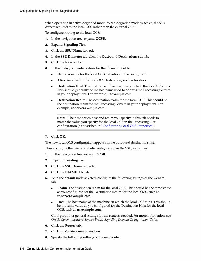
when operating in active degraded mode. When degraded mode is active, the SSU directs requests to the local OCS rather than the external OCS.
To configure routing to the local OCS:
1. In the navigation tree, expand OCSB.
2. Expand Signaling Tier.
3. Click the SSU Diameter node.
4. In the SSU Diameter tab, click the Outbound Destinations subtab.
5. Click the New button.
6. In the dialog box, enter values for the following fields:
■ Name: A name for the local OCS definition in the configuration.
■ Alias: An alias for the local OCS destination, such as localocs.
■ Destination Host: The host name of the machine on which the local OCS runs. This should generally be the hostname used to address the Processing Servers in your deployment. For example, us.example.com.
■ Destination Realm: The destination realm for the local OCS. This should be the destination realm for the Processing Servers in your deployment. For example, ro.server.example.com.
7. Click OK.
The new local OCS configuration appears in the outbound destinations list.
Now configure the peer and route configuration in the SSU, as follows:
1. In the navigation tree, expand OCSB.
2. Expand Signaling Tier.
3. Click the SSU Diameter node.
4. Click the DIAMETER tab.
5. With the default node selected, configure the following settings of the General tab:
■ Realm: The destination realm for the local OCS. This should be the same value as you configured for the Destination Realm for the local OCS, such as ro.server.example.com.
■ Host: The host name of the machine on which the local OCS runs. This should be the same value as you configured for the Destination Host for the local OCS, such as us.example.com.
Configure other general settings for the route as needed. For more information, see Oracle Communications Service Broker Signaling Domain Configuration Guide.
6. Click the Routes tab.
7. Click the Create a new route icon.
8. Specify the following settings of the new route:
Note: The destination host and realm you specify in this tab needs to match the value you specify for the local OCS in the Processing Tier configuration (as described in "Configuring Local OCS Properties").

Configuring Local OCS Properties
Using Degraded Mode 5-5
■ Name: A name for the route configuration.
■ Action: The routing action to perform for the local OCS. Set to relay.
■ Realm: The destination realm for the local OCS. This should be the same value as you configured for the destination realm for the local OCS, such as ro.server.example.com.
■ Application ID: The application ID of the Diameter application. Retain the default, 4, which represents Diameter Ro.
■ Server: Click the add icon under Server and, in the Server field, specify the host name of the machine on which the local OCS runs. This should be the same value as you configured for the destination host for the local OCS, such as us.example.com.
9. Click the Peers tab.
10. Select the Allow Dynamic Peers check box.
11. Click the Create a new row icon to add a peer definition.
The peer represents the local OCS.
12. Specify the peer settings as follows:
■ Address: This should be the local host address, 127.0.0.1.
■ Host: The host name of the machine on which the local OCS runs. This should be the same value as you configured for the destination host for the local OCS, such as us.example.com.
■ Port: The number on which the local OCS listens for Diameter traffic, 3588.
■ Protocol: The network protocol to use for the local OCS, tcp.
The Watchdog check box can remain disabled.
13. Click OK.
The Signaling Tier is now configured to route Diameter traffic to the local OCS.
Configuring Local OCS PropertiesThe local OCS settings define properties for the Service Broker component that performs the functions of the external OCS when it is unavailable.
This section applies to non-orchestrated, passthrough mediation of charging-related traffic. See "Configuring Degraded Mode for Orchestrated Mediation" for information on orchestrated mediation.
To configure local OCS properties:
1. In the navigation tree, expand OCSB.
2. Expand Processing Tier.
3. Expand Passthrough Mediation.
4. Click the Degraded Mode node.
5. In the General tab, specify the following settings:
■ Local OCS realm: The destination realm for the local OCS, such as ro.server.example.com. This value should reflect the realm for the Processing Servers in the Service Broker deployment.

Configuring a Default Service Access Decision
5-6 Online Mediation Controller Implementation Guide
■ Local OCS host: The host name of the machine on which the local OCS runs, such as us.example.com. This value should reflect the host name used to address the Processing Servers in the Service Broker deployment.
■ UserProfile timeout: The time-out value, in milliseconds, for Service Broker access attempts to the Subscriber Store database. This timeout applies only when the Use Global Id in degraded mode value is set to true.
■ Use Global Id in degraded mode: If true, Service Broker attempts to correlate the network IDs in incoming requests to subscriber global IDs retrieved from the Subscriber Store. This gives Service Broker the ability to perform in-order CDR playback for a given subscriber across different devices.
6. Click Apply.
7. Under the Passthrough Mediation node in the navigation tree, click the Routing node.
The routing information enables Service Broker to route Diameter messages by mapping an origin realm to a destination address, the local OCS in this case.
8. In the Routing tab, configure the following settings:
■ Local Host: The host name of the machine on which the local OCS runs, such as us.example.com. This value should reflect the host name used to address the Processing Servers in the Service Broker deployment.
■ Origin Realm: The realm value that identifies requests to be handled in passthrough mode. The default value is aa.origin.realm. A request with any other Origin-Realm value is handled as orchestrated mediation traffic by Service Broker.
9. Click Apply.
Configuring a Default Service Access DecisionIn an Online Mediation Controller implementation, Service Broker can perform the role of a RADIUS server, applying service authorization and authentication decisions to incoming requests. In this role, Service Broker acts as the access enforcement point for network services.
When it receives a user request for a service, Service Broker retrieves the service authorization information for a given user from the external OCS. If the user is authorized to access the service, Service Broker also gets the credentials for that user from the OCS. It uses the credentials to validate those in the incoming request. Service Broker permits or denies access to a service for the user based on the results.
You can configure a default RADIUS authentication decision for Service Broker to apply when it is in active degraded mode, when the external OCS is unavailable.
To configure the default credit authorization decision:
1. In the navigation tree, expand OCSB.
2. Expand Processing Tier.
3. Click RADIUS Mediation.
4. In the degraded-mode-behavior field, enter one of the following values:
■ reject: Blocks all requests.
■ allow: Permits all requests.
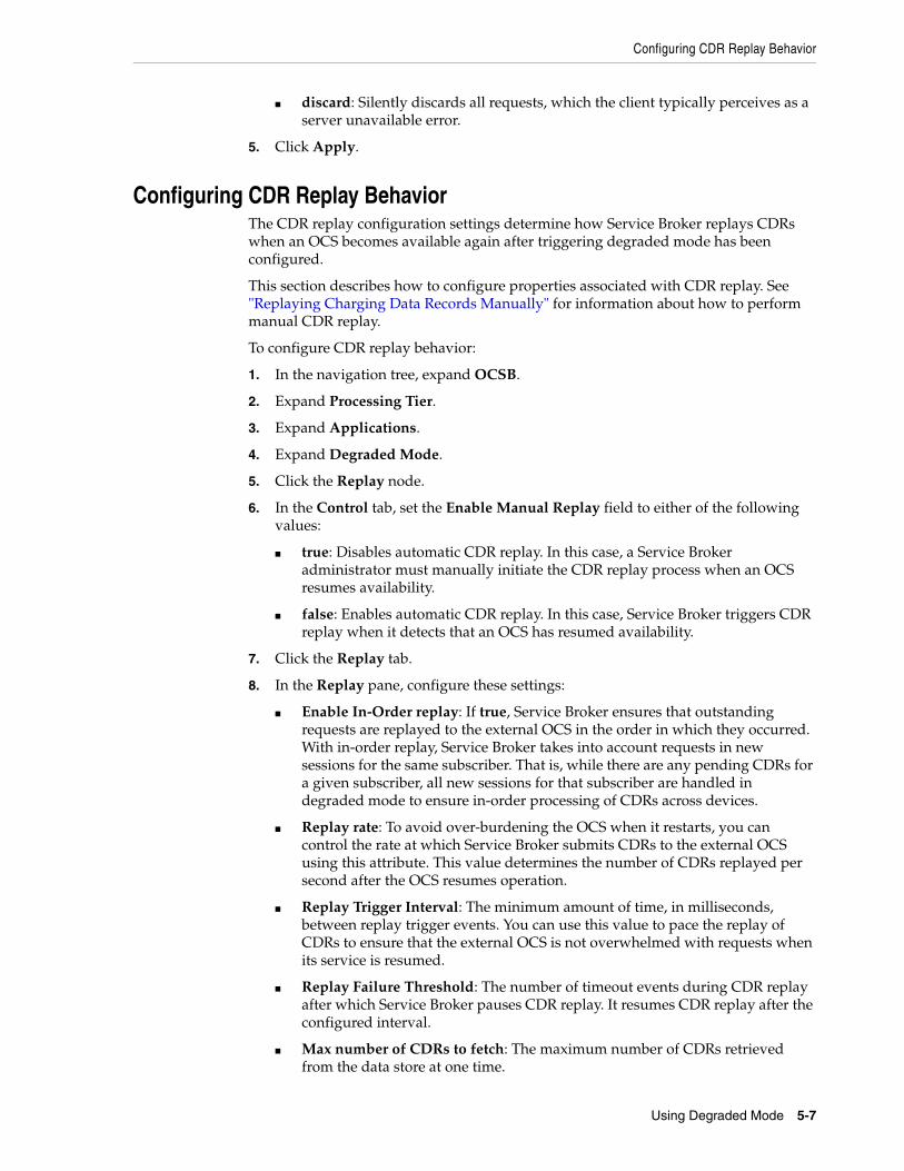
Configuring CDR Replay Behavior
Using Degraded Mode 5-7
■ discard: Silently discards all requests, which the client typically perceives as a server unavailable error.
5. Click Apply.
Configuring CDR Replay BehaviorThe CDR replay configuration settings determine how Service Broker replays CDRs when an OCS becomes available again after triggering degraded mode has been configured.
This section describes how to configure properties associated with CDR replay. See "Replaying Charging Data Records Manually" for information about how to perform manual CDR replay.
To configure CDR replay behavior:
1. In the navigation tree, expand OCSB.
2. Expand Processing Tier.
3. Expand Applications.
4. Expand Degraded Mode.
5. Click the Replay node.
6. In the Control tab, set the Enable Manual Replay field to either of the following values:
■ true: Disables automatic CDR replay. In this case, a Service Broker administrator must manually initiate the CDR replay process when an OCS resumes availability.
■ false: Enables automatic CDR replay. In this case, Service Broker triggers CDR replay when it detects that an OCS has resumed availability.
7. Click the Replay tab.
8. In the Replay pane, configure these settings:
■ Enable In-Order replay: If true, Service Broker ensures that outstanding requests are replayed to the external OCS in the order in which they occurred. With in-order replay, Service Broker takes into account requests in new sessions for the same subscriber. That is, while there are any pending CDRs for a given subscriber, all new sessions for that subscriber are handled in degraded mode to ensure in-order processing of CDRs across devices.
■ Replay rate: To avoid over-burdening the OCS when it restarts, you can control the rate at which Service Broker submits CDRs to the external OCS using this attribute. This value determines the number of CDRs replayed per second after the OCS resumes operation.
■ Replay Trigger Interval: The minimum amount of time, in milliseconds, between replay trigger events. You can use this value to pace the replay of CDRs to ensure that the external OCS is not overwhelmed with requests when its service is resumed.
■ Replay Failure Threshold: The number of timeout events during CDR replay after which Service Broker pauses CDR replay. It resumes CDR replay after the configured interval.
■ Max number of CDRs to fetch: The maximum number of CDRs retrieved from the data store at one time.
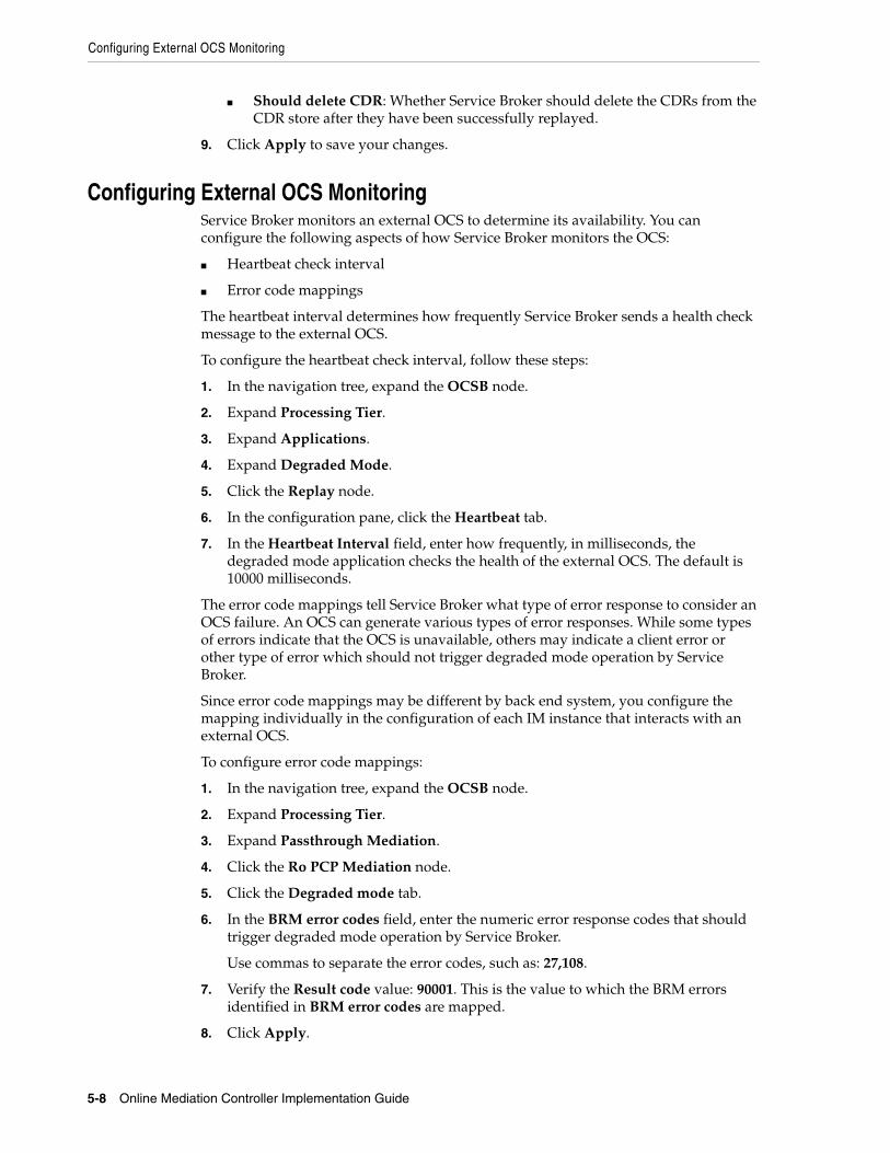
Configuring External OCS Monitoring
5-8 Online Mediation Controller Implementation Guide
■ Should delete CDR: Whether Service Broker should delete the CDRs from the CDR store after they have been successfully replayed.
9. Click Apply to save your changes.
Configuring External OCS MonitoringService Broker monitors an external OCS to determine its availability. You can configure the following aspects of how Service Broker monitors the OCS:
■ Heartbeat check interval
■ Error code mappings
The heartbeat interval determines how frequently Service Broker sends a health check message to the external OCS.
To configure the heartbeat check interval, follow these steps:
1. In the navigation tree, expand the OCSB node.
2. Expand Processing Tier.
3. Expand Applications.
4. Expand Degraded Mode.
5. Click the Replay node.
6. In the configuration pane, click the Heartbeat tab.
7. In the Heartbeat Interval field, enter how frequently, in milliseconds, the degraded mode application checks the health of the external OCS. The default is 10000 milliseconds.
The error code mappings tell Service Broker what type of error response to consider an OCS failure. An OCS can generate various types of error responses. While some types of errors indicate that the OCS is unavailable, others may indicate a client error or other type of error which should not trigger degraded mode operation by Service Broker.
Since error code mappings may be different by back end system, you configure the mapping individually in the configuration of each IM instance that interacts with an external OCS.
To configure error code mappings:
1. In the navigation tree, expand the OCSB node.
2. Expand Processing Tier.
3. Expand Passthrough Mediation.
4. Click the Ro PCP Mediation node.
5. Click the Degraded mode tab.
6. In the BRM error codes field, enter the numeric error response codes that should trigger degraded mode operation by Service Broker.
Use commas to separate the error codes, such as: 27,108.
7. Verify the Result code value: 90001. This is the value to which the BRM errors identified in BRM error codes are mapped.
8. Click Apply.

Configuring Degraded Mode for Orchestrated Mediation
Using Degraded Mode 5-9
Configuring Service Unit Counters Counters in the Service Broker configuration comprise the network service units that you can adapt to your Diameter application requirements.
By default, the predefined counters are based upon the requested service in the Diameter request. Specifically, they are based on the content of the REQUESTED-SERVICE-UNITS AVP, which can be:
■ CC-Time is mapped to code 420
■ CC-Total-Octets is mapped to code 421
■ CC-Input-Octets is mapped to code 412
■ CC-Output-Octets is mapped to code 414
■ CC-Service-Specific-Units is mapped to code 417
To modify the default unit counter configuration:
1. In the navigation tree, expand OCSB.
2. Expand Processing Tier.
3. Expand Applications.
4. Expand Degraded Mode.
5. Select LocalOCF.
6. In the General tab, verify the implementation class that performs service unit calculations. The default is unitCalculatorObjectName. You should modify this value only if you have implemented a custom unit calculator.
7. Click the Counters tab.
8. In the Counters pane, modify the default counter configuration by selecting a counter from the list and clicking the Update button.
9. In the Update dialog box, enter values for these fields:
■ type: The AVP code number that represents the counter type.
■ value: The initial unit value for this counter type.
10. Click OK to save your configuration changes.
Configuring Degraded Mode for Orchestrated MediationSections "Configuring the Signaling Tier for Degraded Mode" and "Configuring Local OCS Properties" describe how to configure degraded mode for passthrough charging mediation. Alternatively, you can configure degraded mode for orchestrated mediation, in which charging-related traffic is handled by the Orchestration Engine and applicable IMs.
Service Broker supports degraded mode for external systems through the following IM types:
■ IM-OCF
■ IM-OCF PCP
■ IM-OFCF PCP
Configuring degraded mode for orchestrated OCS mediation involves the following general steps:
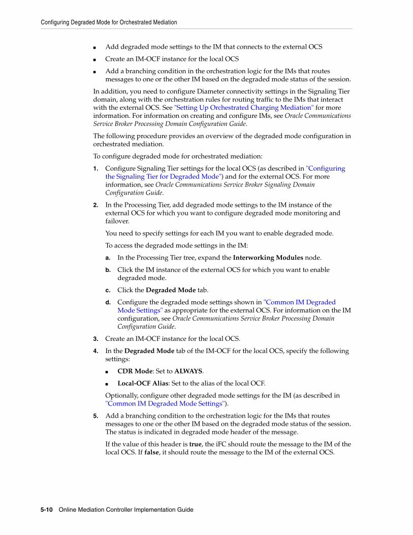
Configuring Degraded Mode for Orchestrated Mediation
5-10 Online Mediation Controller Implementation Guide
■ Add degraded mode settings to the IM that connects to the external OCS
■ Create an IM-OCF instance for the local OCS
■ Add a branching condition in the orchestration logic for the IMs that routes messages to one or the other IM based on the degraded mode status of the session.
In addition, you need to configure Diameter connectivity settings in the Signaling Tier domain, along with the orchestration rules for routing traffic to the IMs that interact with the external OCS. See "Setting Up Orchestrated Charging Mediation" for more information. For information on creating and configure IMs, see Oracle Communications Service Broker Processing Domain Configuration Guide.
The following procedure provides an overview of the degraded mode configuration in orchestrated mediation.
To configure degraded mode for orchestrated mediation:
1. Configure Signaling Tier settings for the local OCS (as described in "Configuring the Signaling Tier for Degraded Mode") and for the external OCS. For more information, see Oracle Communications Service Broker Signaling Domain Configuration Guide.
2. In the Processing Tier, add degraded mode settings to the IM instance of the external OCS for which you want to configure degraded mode monitoring and failover.
You need to specify settings for each IM you want to enable degraded mode.
To access the degraded mode settings in the IM:
a. In the Processing Tier tree, expand the Interworking Modules node.
b. Click the IM instance of the external OCS for which you want to enable degraded mode.
c. Click the Degraded Mode tab.
d. Configure the degraded mode settings shown in "Common IM Degraded Mode Settings" as appropriate for the external OCS. For information on the IM configuration, see Oracle Communications Service Broker Processing Domain Configuration Guide.
3. Create an IM-OCF instance for the local OCS.
4. In the Degraded Mode tab of the IM-OCF for the local OCS, specify the following settings:
■ CDR Mode: Set to ALWAYS.
■ Local-OCF Alias: Set to the alias of the local OCF.
Optionally, configure other degraded mode settings for the IM (as described in "Common IM Degraded Mode Settings").
5. Add a branching condition to the orchestration logic for the IMs that routes messages to one or the other IM based on the degraded mode status of the session. The status is indicated in degraded mode header of the message.
If the value of this header is true, the iFC should route the message to the IM of the local OCS. If false, it should route the message to the IM of the external OCS.
Triggering Degraded Mode Manually
Using Degraded Mode 5-11
Common IM Degraded Mode SettingsThe IMs that support degraded mode have common configuration settings related to degraded mode operation. This section provides an overview of the common settings. For more information about a particular type of IM, see Oracle Communications Service Broker Processing Domain Configuration Guide.
The common degraded mode IM settings are:
■ CDR Mode: The mode in which Service Broker writes CDRs to local storage, from these options:
■ Normal: Service Broker writes CDRs only after it assumes the functions of the external OCS.
■ History: After it assumes the functions of the external OCS, Service Broker writes CDRs that reflect the history of each active session, including for requests received prior to assuming the active OCS role.
■ Always: Service Broker writes CDRs always.
■ CDR Writer Impl: The internal class that performs CDR writing. This can be one of the following values:
■ oracle.ocsb.app.rcc.ocfproxy.cdrwriter.CDRWriterImpl: Writes CDRs to the degraded mode service. This is the standard implementation to use for degraded mode processing.
■ com.convergin.common.diameter.ocfproxy.CDRWriterLogImpl: Writes information to the log only. This is useful for testing.
■ CDR Writer Service The CDR writer service that Service Broker uses, if not the default. This field should remain blank, as it is by default.
■ Degraded Mode Timer: The period of time, in milliseconds, that Service Broker waits for a response from the online charging server. If the online charging server does not respond within the specified period of time, the user session is switched to degraded mode.
■ Local-OCF Alias: Specifies the alias of the local OCS. This alias is mapped to the destination host and destination realm of the local online charging server as defined in the configuration of Diameter SSU outbound routing rules. See the discussion of Diameter SSU in Oracle Communications Service Broker Signaling Domain Configuration Guide for more information.
■ Local-OCF External Protocol: Specifies the protocol that Service Broker uses to communicate with the local online charging server. Default value: Ro
■ Degraded Mode Error Codes: The error response code from the external OCS that indicates a failure for which degraded mode should be activated. Specify as comma-separated integers.
For example:
5012,5023
Triggering Degraded Mode ManuallyTo place Service Broker in active degraded mode manually, you need to enable manual triggering of degraded mode operation.
To enable manual triggering of degraded mode, perform the following steps:
1. In the navigation tree, expand OCSB.
Replaying Charging Data Records Manually
5-12 Online Mediation Controller Implementation Guide
2. Expand Processing Tier.
3. Expand Applications.
4. Expand DegradedMode.
5. Select Replay.
6. In the Control tab, set the Enable Manual Degraded Mode value to true.
This enables degraded mode to be activated manually.
If false, degraded mode can only be activated automatically, that is, in response to network events.
7. Click the Apply button.
After enabling manual degraded mode triggering, you can trigger degraded mode by invoking the markSystemStatusAsDegraded operation in the following runtime MBean:
oracle.ocsb.app.rcc.service.dmode.mbeanDegradedModeMBean
To access the runtime MBean, connect to the managed server JMX process using any JMX client software.
Replaying Charging Data Records ManuallyIn most deployments, Service Broker will be configured to replay CDRs to the external OCS automatically, when it detects that the OCS has resumed service. Alternatively, you can disable automatic CDR replays, and instead invoke CDR replay manually when needed.
To enable manual replay of CDRs, perform the following steps:
1. In the navigation tree, expand OCSB.
2. Expand Processing Tier.
3. Expand Applications.
4. Expand DegradedMode.
5. Select Replay.
6. In the Control tab, set the Enable Manual Replay value to true.
This disables automatic CDR replay and enables manual replay.
7. Click the Apply button.
After enabling manual CDR replay, you can trigger CDR replay using the startManualReplay operation in the following runtime MBean:
oracle.ocsb.app.rcc.service.dmode.mbeanDegradedModeMBean
Note that the operation does not replay all outstanding CDRs. It only replays the number of CDRs configured as the maximum number of CDRs to fetch in the replay configuration (1000, by default). To automatically replay all outstanding CDRs, you must create an MBean script that repeatedly invokes the startManualReplay operation.
See "Configuring CDR Replay Behavior" for information on the maximum number of CDRs to fetch setting.

6
Using the Event Notification Framework 6-1
6Using the Event Notification Framework
The Event Notification Framework provides a way for complementary applications to publish events to external Operational Support Systems (OSSs).
This chapter describes the Event Notification Framework, how to set it up and use it.
About the Event Notification FrameworkComplementary applications use the Event Notification Framework to publish events. The type of event and its timing are application-specific.
Events can be targeted to internal Service Broker components, or to external systems, such as your OSS.
Complementary applications fire events towards external system, to inform them of events that occur during application execution. For example, when a subscriber’s state changes, or when a subscriber’s monthly usage reaches a threshold.
Complementary applications fire events towards internal Service Broker components, to request them to perform an action. For example, request sending a text message to a subscriber using the Short Message Service (SMS), or to change the subscriber’s state.
Firing events towards internal Service Broker components is necessary for optimization purposes; even though complementary applications can send requests to other Service Broker components internally, applications running on the session’s setup path should optimally delegate requests, through the Event Notification Framework, to other entities which will asynchronous invoke execution of the requests, thus reducing the execution time of the complementary applications running on the session setup path.
When targeting events at internal Service Broker components you need to run a built-in Event Processor. See "About the Event Processor" for more information.
When targeting events to external systems, such as your OSS, you use an asynchronous web services Event Notification API to consume these events in your system. See "Using the Event Notification API" for more information.
You can target events at only one destination, that is either an external OSS application, or the Event Processor.
If you target events at an external OSS application, then you have to filter events published by built-in complementary applications and forward them to the Event Processor. Otherwise, you will harm the functionality of the built-in complementary applications. Forwarding events to the Event Processor is necessary only if you deploy one or more of the built-in complementary applications. The exact events that you need to filter and forward to the Event Processor depends on built-in application that
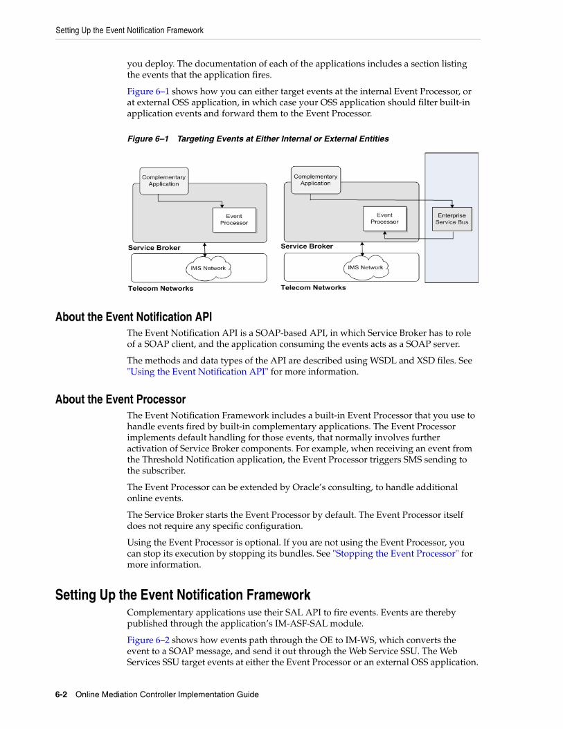
Setting Up the Event Notification Framework
6-2 Online Mediation Controller Implementation Guide
you deploy. The documentation of each of the applications includes a section listing the events that the application fires.
Figure 6–1 shows how you can either target events at the internal Event Processor, or at external OSS application, in which case your OSS application should filter built-in application events and forward them to the Event Processor.
Figure 6–1 Targeting Events at Either Internal or External Entities
About the Event Notification APIThe Event Notification API is a SOAP-based API, in which Service Broker has to role of a SOAP client, and the application consuming the events acts as a SOAP server.
The methods and data types of the API are described using WSDL and XSD files. See "Using the Event Notification API" for more information.
About the Event ProcessorThe Event Notification Framework includes a built-in Event Processor that you use to handle events fired by built-in complementary applications. The Event Processor implements default handling for those events, that normally involves further activation of Service Broker components. For example, when receiving an event from the Threshold Notification application, the Event Processor triggers SMS sending to the subscriber.
The Event Processor can be extended by Oracle’s consulting, to handle additional online events.
The Service Broker starts the Event Processor by default. The Event Processor itself does not require any specific configuration.
Using the Event Processor is optional. If you are not using the Event Processor, you can stop its execution by stopping its bundles. See "Stopping the Event Processor" for more information.
Setting Up the Event Notification FrameworkComplementary applications use their SAL API to fire events. Events are thereby published through the application’s IM-ASF-SAL module.
Figure 6–2 shows how events path through the OE to IM-WS, which converts the event to a SOAP message, and send it out through the Web Service SSU. The Web Services SSU target events at either the Event Processor or an external OSS application.

Configuration Workflow
Using the Event Notification Framework 6-3
In either case, you configure the internal Service Broker Event Processor to receive incoming events.
Figure 6–2 also shows the Service Broker components required to set up the Event Notification Framework.
Figure 6–2 Service Broker Components Required by the Event Notification Framework
Configuration WorkflowThis section assumes that you have already deployed and configured the complementary application that publishes events and its related IM-ASF-SAL module.
To set up the Event Notification Framework:
1. In the Web Services SSU, configure Service Broker as web services client. See the discussion about SOAP client parameters in "Configuring SOAP Web Services Access" in Oracle Communications Signaling Domain Configuration Guide.
2. In the Web Services SSU, configure the target consuming events. See "Configuring Target Event Consumers".
3. Deploy and configure an IM-WS module. See "Deploying and Configuring IM-WS".
4. Route events to IM-WS. See "Routing Events to IM-WS".
5. Enable HTTP network access by opening an HTTP listening port. See "Enabling HTTP Network Access".
6. Route incoming SOAP events to the Event Processor. See "Routing Incoming Events to the Event Processor".
Configuring Target Event ConsumersIn the Web Services SSU, configure event consumers, as described in "Configuring Routing Rules for Outgoing Web Services Messages" in Oracle Communications Service Broker Signaling Domain Configuration Guide.
Configuration Workflow
6-4 Online Mediation Controller Implementation Guide
You can define two or more consumers having a different URL, that share the same alias, thereby adding a level of redundancy, treating all consumers as one logical destination, and balancing the load among consumers.
In the Administration Console:
1. In the navigation tree, expand the OCSB node.
2. Expand the Signaling Tier node.
3. Expand the SSU Web Services node.
4. Select the General node.
5. In the SSU WS tab, select the Outgoing Routing Rules tab.
6. Click the New button. The New dialog box appears.
7. In the Name field, enter a name for the target event consumer.
8. In the Alias field, enter an alias for the target event consumer.
If you target events at the Event Processor, enter sbeventprocess. Otherwise, enter an alias that represents the external OSS application that you are targeting. For example: esb.
9. In the Web Service URI, enter the Web URI of the target event consumer:
If you target events at the Event Processor, enter:
http://ip:port/soap/Events
Where:
ip: the address of the Signaling Servers in the Signaling Domain where the Web Services SSU is running. This should be the address of the Signaling Server or server cluster in your deployment.
port: the Signaling Servers’ web services port.
Otherwise, enter the URI of the external OSS application that you are targeting, that is a web services server, in the format:
http://address:port/web-service-name.
For example, http://telmobil.esb.org:80/eventnotification.
10. Fill up the remaining fields as described in "Configuring Routing Rules for Outgoing Web Services Messages" in Oracle Communications Service Broker Signaling Domain Configuration Guide.
11. Click the OK button.
Deploying and Configuring IM-WSDeploy the IM-WS module as described in "Managing Interworking Modules" in Oracle Communications Service Broker Processing Domain Configuration Guide.
In the Administration Console:
1. In the navigation tree, expand the OCSB node.
2. Expand the Processing Tier node, and then the Interworking Modules node.
3. Click on IM Management.
4. In the IM Management tab, click New.
5. From the Type list, select IMWS.

Configuration Workflow
Using the Event Notification Framework 6-5
6. In the Name field, enter a module instance name. For example, imws_instance.
7. Click the OK button.
8. Click the Commit button.
Configure the IM-WS module as described in "Configuring the IM-WS" in Oracle Communications Service Broker Processing Domain Configuration Guide.
Specifically, in the Web Service tab, set the following fields as described:
■ In the Web Service Alias field, enter the alias of the target event consumer that you configured in the Web Services SSU in step 2.
■ From the Web Service Type list box, select SOAP.
■ In the Web Service Body Type, enter eventnotification.
Routing Events to IM-WSCreate an appropriate orchestration logic that routes events arriving from IM-ASF-SAL towards IM-WS. Use the Orchestration Studio to create the orchestration logic. See Oracle Communications Service Broker Orchestration Studio User’s Guide.
Specifically, you need to set a condition that identify SAL messages the Method set to MESSAGE and the To header containing the string events_service. For example:
To: sip:postEventRequest@events_service
Enabling HTTP Network AccessYou enable HTTP network access to let incoming events reach the Event Processor.
To configure HTTP connectivity for the incoming events:
1. In the navigation tree, expand OCSB.
2. Expand the Signaling Tier node.
3. Expand the SSU Web Services node.
4. Select the General node.
5. Select the HTTP tab.
6. In the Server subtab, select the Network Access subtab.
7. Click New.
8. In the dialog box, set the properties for the HTTP listener as follows:
■ Server Address: The local IP address or host name to which the port is bound. This should be the address of the Signaling Server or server cluster in your deployment.
■ Server Port: An available listening port on Service Broker serving API client requests, such as 8989. This is the port number on which the Signaling Servers will listen for incoming HTTP requests to the Event Processor.
■ Protocol: The protocol used by incoming events. Choose HTTPS for secure HTTP or HTTP for unsecured HTTP. Oracle recommends using HTTPS for production deployments.
■ SSL Client Auth: Whether SSL client certificate authentication is required for the connection. Enter false to disable SSL client certificate authentication, or
Stopping the Event Processor
6-6 Online Mediation Controller Implementation Guide
true to require it. Enter true only if using HTTPS for the Protocol, in which case you will also need to set the key store and trust store identifiers.
■ Keystore Id: The key you used when loading the keystore in the Credential Store. Use only with HTTPS. If you are using HTTP, this field can be left blank. If you have not already, load the keystore associated with the ID into the credential store. See Oracle Communications Service Broker Administrator’s Guide for more information about the credential store.
■ Truststore Id: The key you used when loading the trust store into the Credential Store. Use only with HTTPS. If using HTTP, this field can be left blank. See Service Broker Administration Guide for more information about the credential store.
■ Target: The Signaling Server to which this configuration applies. Leave blank to apply the configuration to all Signaling Servers in the deployment. Specify a Signaling Server name only if you want custom settings for individual Signaling Servers.
Routing Incoming Events to the Event ProcessorTo route incoming events to the Event Processor, in the Web Services SSU, create a new incoming routing rule. See the discussion about incoming routing rules in "Configuring the Web Services SSU" in Oracle Communications Service Broker Signaling Domain Configuration Guide.
Specifically, in the new rule, set the following fields as described:
■ In the Service Name field, enter oosEventService.
■ In the Alias field, enter ssu:ocsb/outofsession.
Stopping the Event ProcessorTo stop the Event Processor:
1. In the Administration Console, in the navigation tree, expand OCSB.
2. Expand Domain Management
3. Select Packages
4. In the Filter field, enter axia.oos. The Event Processor bundles will be listed:
■ com.convergin.wcs.axia.oos
■ com.convergin.wcs.axia.oos.ext
■ com.convergin.wcs.axia.oos.ooshash
5. Select a bundle that you want to stop and click the Stop button.
Using the Event Notification APIThe event notification API is a SOAP-based API that you use to consume events, and run your specific business logic in the occurrence of these events.
The event notification API includes a single operation for receiving a notification. In general, any kind of event, triggered by any complementary application, is submitted through this API.
For most deployments, the primary consumer of the API notifications will be the customer’s ESB (for example, Oracle Enterprise Service Bus), filtering the various
Event Notification API Reference
Using the Event Notification Framework 6-7
notifications and distributing them to other OSS modules, based on the type of the event published. However, any other SOAP server that you implement can consume events.
To consume events, you develop a Web service with the WSDL files describing the event notification interface, and deploy the Web service on your SOAP server.
Obtaining WSDL and SchemaThe interface of the Event Notification API and its data types are described in the following files:
■ events_service.wsdl
■ events_interface.wsdl
■ general.xsd
■ events.xsd
You obtain the files from the Signaling Server. To navigate to the WSDL, go to the following address:
http://host:port/soap/events
Where host is the host name or IP address and port is the server port number you specified as the server address. See "Enabling HTTP Network Access".
If the WSDL is accessible, you can start developing your API server application. Many Integrated Development Environments (IDEs) can generate client code you can use as a starting point for your application by importing the WSDL into the IDE.
Event Notification API ReferenceThe rest of this chapter is a reference of the event notification API, describing the operation of the API. It lists the parameters accepted and returned by the operation. It provides examples of HTTP requests and responses for the operation.
Note: In the request and response message examples in this section, line breaks and spaces have been added to the data in the body of the message to improve readability.
Post Event
6-8 Online Mediation Controller Implementation Guide
Post Event
Notifies of the occurrence of an event.
The event can be of any kind. Its characteristic is defined by two fields: the event type and event category. The values of the event type and event category are not limited to a predefined set of values, and are extensible. The values depend on the complementary application initiating the event notification. Each application defines its own set of event types and categories. The events provided by each application is listed in the documentation of each application.
6Request BodyRequest body parameters are:
■ externalCorrelationID: (xs:string) Optional. An event identifier, that you can use to correlate to the event.
■ senderIdentifier: (xs:string) Optional. The identifier of the complementary application submitting the event.
■ subscriberID: (SubscriberID) Optional. The identifier of the subscriber that owns the session for which the application sending the event was invoked. SubscriberID comprises:
■ code: (xs:int) The type of the subscriber identifier value. Possible values are:
* 0: Mobile Subscriber ISDN Number (MSISDN) or Directory Number (DN)
* 1: Mobile Identification Number (MIN) or International Mobile Subscriber Identity (IMSI)
* 2: SIP URI
■ value: (xs:string) The subscriber identifier.
■ type: (xs:string) The event type. Can be any number of characters, including any combination of letters, word characters and spaces.
■ category: (xs:string) The event category. Helps dividing the different types of events into sets of related events. A group of related events is assigned with the same category.
For example, events categorized as internal, are events consumed by internal Service Broker components and submitted by complementary applications to implement built in Service Broker features.
Complementary application developers can define categories as they need.
Can be any number of characters, including any combination of letters, word characters and spaces.
■ description: (xs:string) Optional. A free text description of the event. Can be any number of characters, including any combination of letters, word characters and spaces.
■ additionalParam: (NameValue) Optional. A recursive structure containing event specific parameters. Each parameter is a pair of:
– code: (xs:string) A unique parameter identifier. Can be any number of characters, including any combination of letters, word characters and spaces.
– A choice of:

Post Event
Using the Event Notification Framework 6-9
* value: (xs:string) The parameter value. Can be any number of characters, including any combination of letters, word characters and spaces.
* nameValue (NameValue) more event specific parameters, related to each other, that you want to assemble in one set of parameters.
6Response BodyResponse body parameters are:
■ result: (GenericOutput). The result of the operation. A data structure containing the following parameters:
– fault: (Fault): Optional. A data structure containing the following:
* faultcode: (xs:QName). A code identifying the fault.
* faultstring: (xs:string). A human readable explanation of the fault.
* faultactor: (xs:anyURI) Optional. Information about who caused the fault to happen.
* detail (detail) Optional. Holds event specific error information. A data structure containing a sequence of xs:any and then xs:anyattribute
Built-in complementary applications ignore this parameter.
– externalId (string). The event identifier. This must always be equal to the externalCorrelationID parameter in the request body.
– additionalInformation (NameValue) Optional. A recursive structure containing event specific parameters. See the description of the additionalParam parameter, in the request body. The list of parameters depends on the specific event.
6Example
Example 6–1 Request
<soapenv:Envelope xmlns:soapenv="http://schemas.xmlsoap.org/soap/envelope/" xmlns:even="http://xmlns.oracle.com/axia/events"xmlns:gen="http://xmlns.oracle.com/ocsb/core/general"><soapenv:Header/><soapenv:Body><even:postEventRequestParams><even:externalCorrelationID>71b42285</even:externalCorrelationID><even:senderID>FirstCallApplication</even:senderID><even:subscriberID><gen:code>0</gen:code><gen:value>+14081154970</gen:value></even:subscriberID><even:type>FirstCall</even:type><even:category>Charging</even:category>even:description>account activation complete</even:description></even:postEventRequestParams></soapenv:Body></soapenv:Envelope>
Example 6–2 Response
<S:Envelope xmlns:S="http://schemas.xmlsoap.org/soap/envelope/"> <S:Body><postEventResponseParams xmlns="http://xmlns.oracle.com/axia/events

Post Event
6-10 Online Mediation Controller Implementation Guide
xmlns:ns2="http://xmlns.oracle.com/ocsb/core/general"><even:externalCorrelationID>71b42285</even:externalCorrelationID></postEventResponseParams></S:Body></S:Envelope>
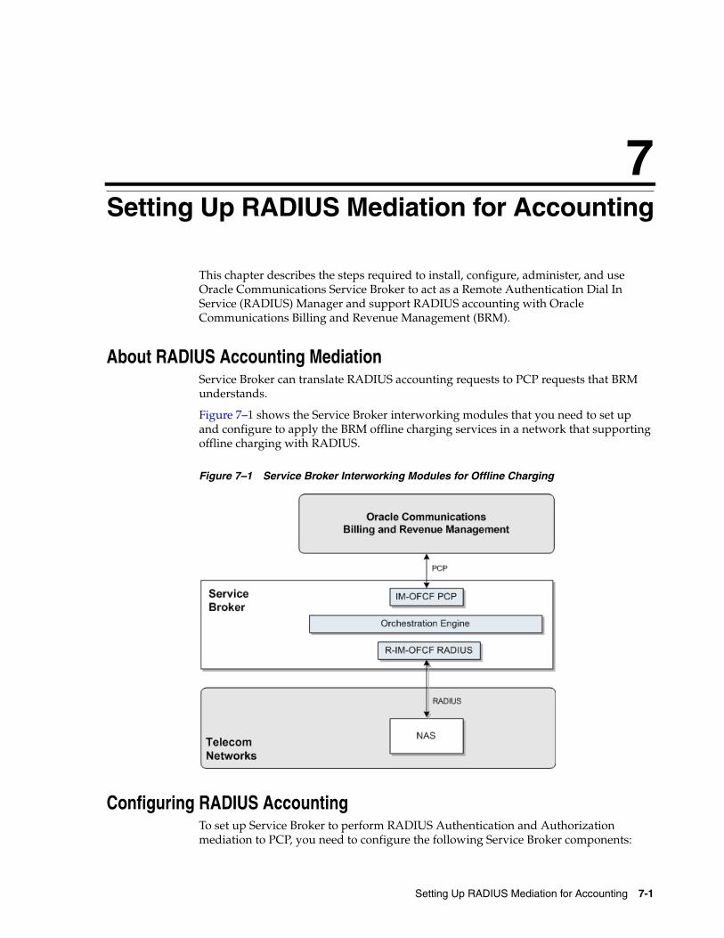
7
Setting Up RADIUS Mediation for Accounting 7-1
7Setting Up RADIUS Mediation for Accounting
This chapter describes the steps required to install, configure, administer, and use Oracle Communications Service Broker to act as a Remote Authentication Dial In Service (RADIUS) Manager and support RADIUS accounting with Oracle Communications Billing and Revenue Management (BRM).
About RADIUS Accounting MediationService Broker can translate RADIUS accounting requests to PCP requests that BRM understands.
Figure 7–1 shows the Service Broker interworking modules that you need to set up and configure to apply the BRM offline charging services in a network that supporting offline charging with RADIUS.
Figure 7–1 Service Broker Interworking Modules for Offline Charging
Configuring RADIUS AccountingTo set up Service Broker to perform RADIUS Authentication and Authorization mediation to PCP, you need to configure the following Service Broker components:
Deploying RADIUS Accounting Mediation
7-2 Online Mediation Controller Implementation Guide
■ RADIUS SSU
■ PCP SSU
■ R-IM-OFCF RADIUS
■ IM-OFCF PCP
■ Orchestration Engine
Deploying RADIUS Accounting MediationTo set up Service Broker to perform RADIUS Accounting mediation to PCP, you need to deploy and configure the following Service Broker components:
■ IM-OFCF PCP and R-IM-OFCF RADIUS
See the chapters "Configuring the IM-OFCF PCP" and "Configuring the R-IM-OFCF RADIUS" in Oracle Communications Service Broker Processing Domain Configuration Guide for more information.
■ Orchestration Engine
See the chapter "Configuring the Orchestration Engine" in Oracle Communications Service Broker Processing Domain Configuration Guide for more information.
■ RADIUS SSU and PCP SSU
See "Configuring the RADIUS SSU" and "Configuring the PCP SSU" in Oracle Communications Service Broker Signaling Domain Configuration Guide for more information.
Configuration WorkFlowTo create an end-to-end configuration for RADUIS accounting:
1. Configure the RADIUS SSU. See "Configuring the RADIUS SSU".
2. Configure the PCP SSU to connect to BRM. See "Connecting to BRM Through PCP".
3. Create an instance of R-IM-OFCF RADIUS and configure it. See "Creating and Configuring an R-IM-OFCF RADIUS Instance".
4. Configure the Orchestration Engine to route the request. See "Creating Orchestration Logic for RADIUS Accounting".
5. Configure the IM-OFCF PCP the interworking module to connect to your BRM installation. See "Configuring the IM-OFCF PCP".
6. Activate the interworking modules. See "Activating the R-IM-OFCF RADIUS and IM-OFCF-PCP Instances".
Configuring the RADIUS SSUConfigure the RADIUS SSU for accounting requests as described in “Configuring the RADIUS SSU” in Oracle Communications Service Broker Signaling Domain Configuration Guide. Use the following configuration data, specifically:
1. Create a new incoming routing rule.
2. Set the parameter Name to the rule name to use.
3. Set Local Realm to any. This is a case-sensitive field.
Configuration WorkFlow
Setting Up RADIUS Mediation for Accounting 7-3
4. Set Alias to the instance name that you are going to use for the R-IM-OFCF RADIUS instance. This instance is create later in the process. See "Creating and Configuring an R-IM-OFCF RADIUS Instance". We will refer to this name as rimocfradius. Set the type of IM instance to RIMOCFRADIUS and the domain id to ocsb.com. The complete string to enter in the Alias fields is:
Connecting to BRM Through PCPTo connect Service Broker to Oracle Communications BRM:
1. Create BRM connection pools in the PCP SSU, as described in "Defining Connection Pools" in the chapter "Configuring the PCP Signaling Server Unit" in Oracle Communications Service Broker Signaling Domain Configuration Guide.
See also "About Connection Pooling" in Oracle Communications Billing and Revenue Management System Administrator’s Guide.
2. Secure the BRM connection pools that you created in step 1, as described in "Securing Connection Pools" in the chapter "Configuring the PCP Signaling Server Unit" in Oracle Communications Service Broker Signaling Domain Configuration Guide.
In the Administration Console:
a. In the navigation tree, expand the OCSB node, and then the Signaling Tier node.
b. Select the SSU PCP node.
c. In the PCP tab, select the Credential Store tab.
d. In the Password area, in the Key field, enter the ID of the connection pool that you want to secure. This should be the Pool ID that you assigned to the connection pool when you created the connection pool in step 1.
e. In the Password area, in the Password field, enter the password of the Oracle Communications BRM client application account used by the connection pool to access the BRM. This should be the password of the account that you configured in the BRM CM Login ID field when you initially defined the connection pool.
f. In the Password area, uncheck the one-way checkbox.
g. In the Password area, click the Set Password button.
h. Repeat steps d through f for each connection pool that you want to secure.
3. Define destination BRM applications, as described in "Defining PCP Network Entities" in the chapter "Configuring the PCP Signaling Server Unit" in Oracle Communications Service Broker Signaling Domain Configuration Guide.
Creating and Configuring an R-IM-OFCF RADIUS InstanceCreate and configure the R-IM-OFCF RADIUS instance for accounting requests as described in “Configuring R-IM-OFCF Radius” in Oracle Communications Service Broker Processing Domain Configuration Guide. Use the following configuration data, specifically:
1. Give the IM a name that matches the Alias used when creating the incoming routing rule in the RADIUS SSU. See "Configuring the RADIUS SSU".

Extending RADIUS Accounting Support
7-4 Online Mediation Controller Implementation Guide
Creating and Configuring an IM-OFCF PCP InstanceCreate and configure the IM-OFCF PCP instance for accounting requests as described in “Configuring IM-OFCF PCP” in Oracle Communications Service Broker Processing Domain Configuration Guide. Use the following configuration data, specifically:
■ Give the IM a name that will be used by the Orchestration Engine when routing requests. We will refer to this name as imofcfpcp.
Creating Orchestration Logic for RADIUS AccountingConfigure the Orchestration Studio to route RADIUS accounting requests to the IM-OFCF PCP instance. See Oracle Communications Service Broker Orchestration Studio User's Guide. Use the following configuration data, specifically:
■ Route the requests to sip:[email protected]
Where imofcfpcp is the IM name you gave for the IM-OFCF PCP instance. See "Creating and Configuring an IM-OFCF PCP Instance".
Activating the R-IM-OFCF RADIUS and IM-OFCF-PCP InstancesTo activate the newly created R-IM-OFCF RADIUS and IM-OFCF-PCP instances:
1. In the Domain Navigation pane, expand OCSB.
2. Expand Processing Tier and then expand Interworking Modules.
3. Select IM Management.
4. Click on the R-IM-OFCF RADIUS instance. The instance name is the same as you gave when you created it. See "Creating and Configuring an R-IM-OFCF RADIUS Instance".
5. Click Activate.
6. Click on the IM-OFCF-PCP instance. The instance name is the same as you gave when you created it. See "Creating and Configuring an IM-OFCF PCP Instance".
7. Click Activate.
Configuring the IM-OFCF PCPConfigure the IM-OFCF-PCP IM for accounting requests as described in “Configuring IM-OFCF PCP” in Oracle Communications Service Broker Processing Domain Configuration Guide. Use the following configuration data, specifically:
1. Set the field Destination Alias to brm.
Extending RADIUS Accounting SupportYou can extend the accounting functionality by adding support for custom RADIUS AVPs. You do that by adding custom AVPs to the RADIUS dictionary in the RADIUS SSU. See “Configuring the RADIUS SSU" in Oracle Communications Service Broker Signaling Domain Configuration Guide for more information.
If you add custom AVPs to the RADIUS dictionary in the RADIUS SSU, you also need to implement custom mappers from RADIUS to Rf (deployed in R-IM-OFCF RADIUS), and from Rf to PCP (deployed in IM-OFCF PCP).
8
Using the Balance Manager 8-1
8Using the Balance Manager
The Oracle Communications Service Broker Balance Manager provides a way to enable prepaid subscribers to check their account balances and replenish ("top up") their accounts either from stored payment account information or by redeeming a voucher.
This chapter describes the Balance Manager feature and the Balance Manager API.
About the Balance Manager FeatureThe Balance Manager feature is implemented in Service Broker by a Balance Manager Service.
The Balance Manager Service integrates with Oracle Billing and Revenue Management (BRM) to access the subscriber billing accounts. Communication between the Balance Manager Service and BRM is over Portal Communications Protocol (PCP).
BRM authenticates the subscribers and maintains the subscriber billing accounts. All subscriber payment information, such as credit card and debit account numbers, is stored on BRM.
To check their balances, top up their account balances from their credit or debit accounts, and redeem vouchers, subscribers can interact with the Balance Manager applications using Interactive Voice Response (IVR), Short Message Service (SMS), or a Web interface. This chapter describes the procedures for implementing IVR and SMS support. It does not describe implementation of a Web interface, but such an interface would use the same Balance Manager Web Service APIs as the IVR and SMS interfaces.
The Balance Manager Web Service mediates between the IVR, SMS, or Web front ends and the Balance Manager Service. The Balance Manager Service translates the WS messages to PCP and communicates with BRM over PCP to perform the requested action in the prepaid accounts on BRM.
Figure 8–1 shows a high level overview of the Balance Manager in context with components that are external to Service Broker.
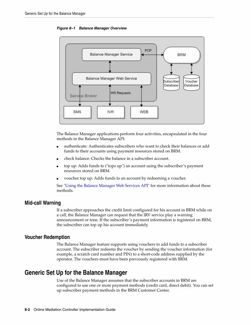
Generic Set Up for the Balance Manager
8-2 Online Mediation Controller Implementation Guide
Figure 8–1 Balance Manager Overview
The Balance Manager applications perform four activities, encapsulated in the four methods in the Balance Manager API:
■ authenticate: Authenticates subscribers who want to check their balances or add funds to their accounts using payment resources stored on BRM.
■ check balance: Checks the balance in a subscriber account.
■ top up: Adds funds to ("tops up") an account using the subscriber’s payment resources stored on BRM.
■ voucher top up: Adds funds to an account by redeeming a voucher.
See "Using the Balance Manager Web Services API" for more information about these methods.
Mid-call WarningIf a subscriber approaches the credit limit configured for his account in BRM while on a call, the Balance Manager can request that the IRV service play a warning announcement or tone. If the subscriber’s payment information is registered on BRM, the subscriber can top up his account immediately.
Voucher RedemptionThe Balance Manager feature supports using vouchers to add funds to a subscriber account. The subscriber redeems the voucher by sending the voucher information (for example, a scratch card number and PIN) to a short-code address supplied by the operator. The vouchers must have been previously registered with BRM.
Generic Set Up for the Balance ManagerUse of the Balance Manager assumes that the subscriber accounts in BRM are configured to use one or more payment methods (credit card, direct debit). You can set up subscriber payment methods in the BRM Customer Center.
Generic Set Up for the Balance Manager
Using the Balance Manager 8-3
Use of the voucher top-up feature also assumes that, if vouchers are to be accepted as payment, BRM has been configured for voucher payments and that the vouchers have been loaded into the BRM database. See the discussion of the Voucher Manager and the Voucher Administration Center in the Service Integration Components guide in the BRM documentation set for information about how to set up vouchers in BRM.
In addition to setting up BRM with subscriber payment information and vouchers, you must configure BRM for subscriber authentication.
Also, there are configuration tasks to perform in Service Broker to enable communication among the various components.
These generic configuration tasks are required for all interfaces to the Balance Manager (IVR, SMS, and Web) and for all the Balance Manager SMS applications: (Balance Manager SMS, Top up App. and Voucher Top-Up).
The generic configuration tasks are as follows:
1. In BRM, create an authentication service. See "Creating an Authentication Service" for details. This step is optional, because you can use an existing authentication service, if one exists, instead of creating a new one.
2. In BRM, create an authentication plan that incorporates the authentication service from step 1. This step is required. See "Creating an Authentication Plan" for details.
3. In BRM, for every subscriber, add the authentication plan to the subscribers’ accounts. This step is required. See "Adding the Authentication Plan to Subscriber Accounts" for details.
4. In the Service Broker Administration Console, configure the authentication service for the application. This step is required. See "Configuring the Authentication Service for the Balance Manager Applications" for details.
5. In the Service Broker Administration Console, configure the Portal Communications Protocol Signaling Server Unit (PCP SSU) to enable communication between Service Broker and BRM. This step is required. See "Configuring the PCP SSU".
6. In the Service Broker Administration Console, configure the Web Services SSU HTTP incoming rule for the Balance Manager. This configuration directs Service Broker how to route Web Service messages to the Balance Manager. This step is required. See "Configuring the HTTP Incoming Rule for the Web Services SSU" for details.
7. In the Service Broker Administration Console, configure the credentials to enable clients of the Balance Manager SOAP Web Services to access Balance Manager API. See "Configuring Web Service Client Credentials" for details.
8. In the Service Broker Administration Console, configure the Balance Manager Web Service. See "Configuring the Balance Manager Web Service" for details.
In addition, there are several required configuration tasks required only for the Balance Manager application, which provides the SMS interface to the Balance Manager. See "SMS Configuration Tasks" for information about these configuration tasks.
Creating an Authentication ServiceBRM must be configured with an authentication service for the Balance Manager to use to authenticate subscribers. You can use an existing BRM authentication service, or you can create a new one.
Generic Set Up for the Balance Manager
8-4 Online Mediation Controller Implementation Guide
To create a new authentication service in BRM:
1. Connect to the BRM Developer Center.
2. In the class browser, navigate to service/authentication.
3. Create a new storable class with no new fields under service/authentication.
It is not necessary to create any new fields because all the information that the Balance Manager needs are the LOGIN and PASSWORD fields, which already exist in the parent service class. The phone number parameter passed by the Balance Manager request maps to the LOGIN field in the BRM service and the PIN maps to the PASSWD field.
4. Click OK.
For more information about creating a new storable class, see the Online Help in the Storable Class Editor in the BRM Developer Center and the discussion of creating custom storable classes in the BRM documentation.
Creating an Authentication PlanIn BRM, create an authentication plan that incorporates the authentication service.
To create an authentication plan:
1. Connect to the BRM Pricing Center.
2. In the Pricing Center application, create a new plan.
3. In the Plan Attributes tab, click Actions - New Service.
The Service Deal dialog box appears.
4. In the Service Deal dialog box, select /service/authentication as the service type and <No deal> for the deal.
5. Click OK.
6. Click OK in the Plan Attributes tab to save the authentication plan.
For more information, see the discussion of creating plans in the BRM documentation about setting up rating and pricing.
Adding the Authentication Plan to Subscriber AccountsEach subscriber account must be associated with the authentication plan.
To associate a subscriber with the authentication plan:
1. Connect to the BRM Customer Center.
2. Select the subscriber in the left panel.
3. In the Purchase Options list, select Add Plan.
4. Select the authentication plan to use for the Balance Manager from the list of plans.
5. Click through the Next buttons to Finish.
For more information about adding a new plan, see the discussion of adding a product with a new service in the BRM Customer Center Help.
Configuring the Authentication Service for the Balance Manager ApplicationsTo configure the authentication service for the Balance Manager feature:

Generic Set Up for the Balance Manager
Using the Balance Manager 8-5
1. In the Service Broker Administration Console, expand the OCSB node.
2. Expand the Processing Tier node.
3. Expand the Applications node.
4. Click the Lock and Edit icon.
5. Expand the Balance Manager node.
6. Click the BRM Authentication item.
7. In the Authentication Service field, enter the name of the BRM authentication service that the Balance Manager applications use to authenticate subscribers.
This is either a pre-existing authentication service in BRM or the one that you created for the Balance Manager. See "Creating an Authentication Service".
8. Click Apply.
Configuring the PCP SSUThe PCP SSU must be configured to enable communication between Service Broker and BRM.
To configure the PCP SSU, follow the instructions in the discussion of configuring PCP Signaling Server Units in the Oracle Communications Service Broker Signaling Domain Configuration Guide.
Configuring the HTTP Incoming Rule for the Web Services SSUTo set the HTTP incoming rule for the WS SSU:
1. In the Service Broker Administration Console, expand the OCSB node.
2. Expand the Signaling Tier node.
3. Click the Lock and Edit icon.
4. Expand the SSU Web Services node.
5. Click the General item.
6. Click the SSU WS tab.
7. Click the Incoming Routing Rules subtab.
8. Click New.
9. In the dialog box, set the incoming routing rules as follows:
■ Set the Name field to an incoming rule name of your choice.
■ Set the Service Name field to BalanceManagerService.
■ Set the Alias field to ssu:topup@ocsb/topup.
10. Click OK.
For more information, see the discussion of configuring routing rules for incoming Web Service messages in Oracle Communications Service Broker Signaling Domain Configuration Guide.
Configuring Web Service Client CredentialsYou can set up credentials to authenticate external Web Services clients for access to the Balance Manager Web Service.
Generic Set Up for the Balance Manager
8-6 Online Mediation Controller Implementation Guide
To configure credentials for the Web Service:
1. In the Service Broker Administration Console, expand the OCSB node.
2. Expand the Signaling Tier node.
3. Click the Lock and Edit icon.
4. Expand the SSU Web Services node.
5. Click the General item.
6. Click the SOAP tab.
7. Click the Credential Store subtab.
8. Enter credentials for the Web Service client. See the discussion of authenticating SOAP requests with WSSE UsernameToken credentials in Oracle Communications Service Broker Signaling Domain Configuration Guide for detailed instructions on configuring credentials.
Credential checking is optional and disabled by default. To enable it, set the Authentication Method field in the Balance Manager endpoint to USERNAME_TOKEN, as described in the "Configuring the Balance Manager Web Service" section.
Configuring the Balance Manager Web ServiceTo configure the Balance Manager SOAP Web Service:
1. In the Service Broker Administration Console, expand the OCSB node.
2. Expand the Signaling Tier node.
3. Click the Lock and Edit icon.
4. Expand the SSU Web Services node.
5. Click the Balance Manager item.
6. Click the Balance Manager tab.
7. Click the End Point subtab.
8. Click New.
9. In the dialog box, set the Balance Manager endpoint as follows:
■ Set the URI field to /BalanceManagerService.
■ Set the Authentication Method field to either NONE or USERNAME_TOKEN.
The USER_NAME token is for WSSE Username Token security. As an alternative, you can authenticate credentials using HTTP Basic Auth. See the discussion of HTTP server security contexts in Oracle Communications Service Broker Signaling Domain Configuration Guide for information about using Basic Auth.
■ If the Authentication Method field is USERNAME_TOKEN, set the Username field to the user name of the service. This value is ignored if the Authentication Method is NONE.
■ If the Authentication Method field is USERNAME_TOKEN, set the Credential Key field to the key that you configured for the service in the Credential Store. This value is ignored if the Authentication Method is NONE.

Using the Balance Manager IVR Interface
Using the Balance Manager 8-7
10. Click OK.
Using the Balance Manager IVR InterfaceSubscribers can check their balances and top up their accounts from their phone keypads using dual-tone multifrequency (DTMF) technology. They can add value using the credit or debit information associated with their accounts, or they can redeem a voucher to add value to their own or any other prepaid account.
The IVR implementation uses voice xml (vxml) scripts to play prompts and to gather DTMF input from the subscriber. Examples of these prompts are "Please enter the 10 digit telephone number.", "Please enter the amount you want add.", "You have entered an invalid telephone number pin combination.", and so on.
IVR ComponentsThe following components, external to Service Broker, are required to interact with the Balance Manager Web Service to support IVR interaction:
■ IVR Web Server
The IVR Web Server acts as a document server for the vxml scripts and as a Web Service client to the Balance Manager Web Service.
The vxml scripts are hosted in a servlet or JSP container to enable communication with the Top Up Web service.
■ Media Server
The media server plays the vxml scripts. Operators can use the media server of their choice.
■ Media Gateway
The Media Gateway processes the incoming IVR communication from the caller and generates the SIP call with the initial vxml script.
The WS SSU in Service Broker receives the Web Service requests and routes them to the Balance Manager Web Service for processing.
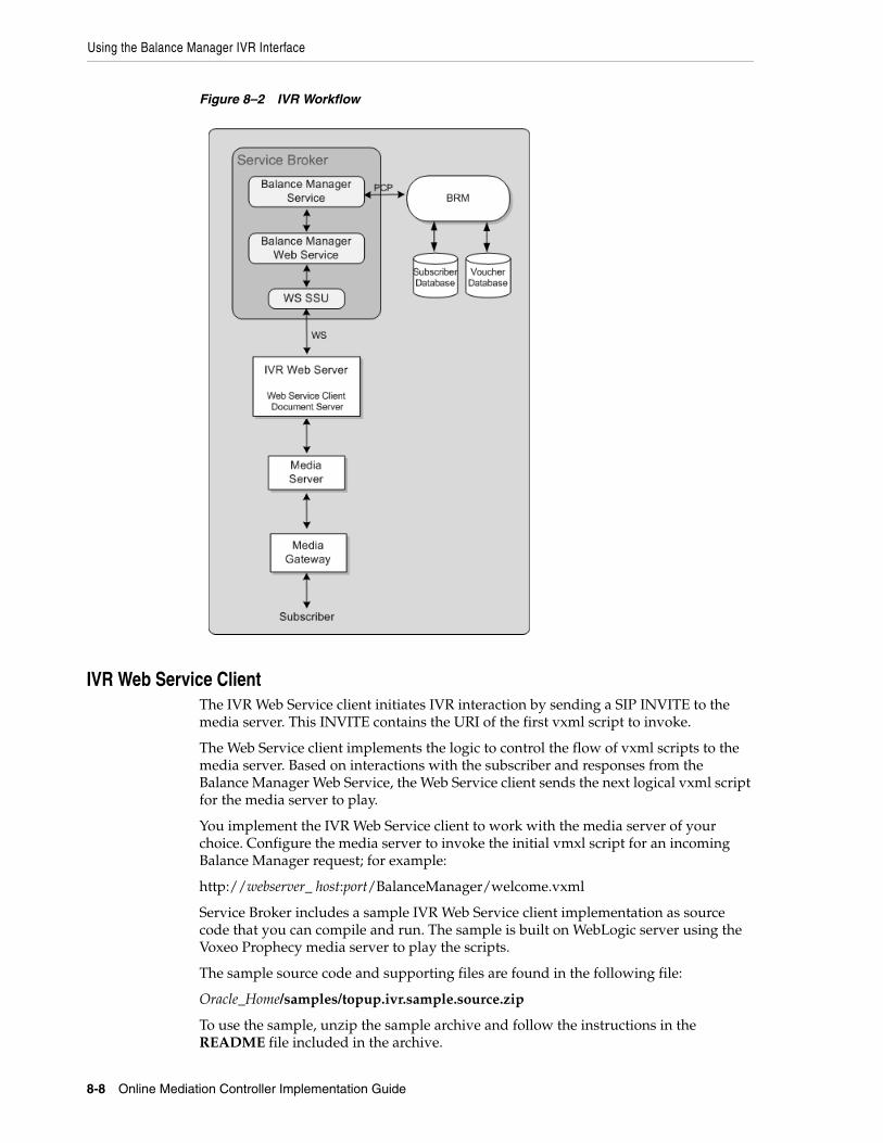
Using the Balance Manager IVR Interface
8-8 Online Mediation Controller Implementation Guide
Figure 8–2 IVR Workflow
IVR Web Service ClientThe IVR Web Service client initiates IVR interaction by sending a SIP INVITE to the media server. This INVITE contains the URI of the first vxml script to invoke.
The Web Service client implements the logic to control the flow of vxml scripts to the media server. Based on interactions with the subscriber and responses from the Balance Manager Web Service, the Web Service client sends the next logical vxml script for the media server to play.
You implement the IVR Web Service client to work with the media server of your choice. Configure the media server to invoke the initial vmxl script for an incoming Balance Manager request; for example:
http://webserver_ host:port/BalanceManager/welcome.vxml
Service Broker includes a sample IVR Web Service client implementation as source code that you can compile and run. The sample is built on WebLogic server using the Voxeo Prophecy media server to play the scripts.
The sample source code and supporting files are found in the following file:
Oracle_Home/samples/topup.ivr.sample.source.zip
To use the sample, unzip the sample archive and follow the instructions in the README file included in the archive.
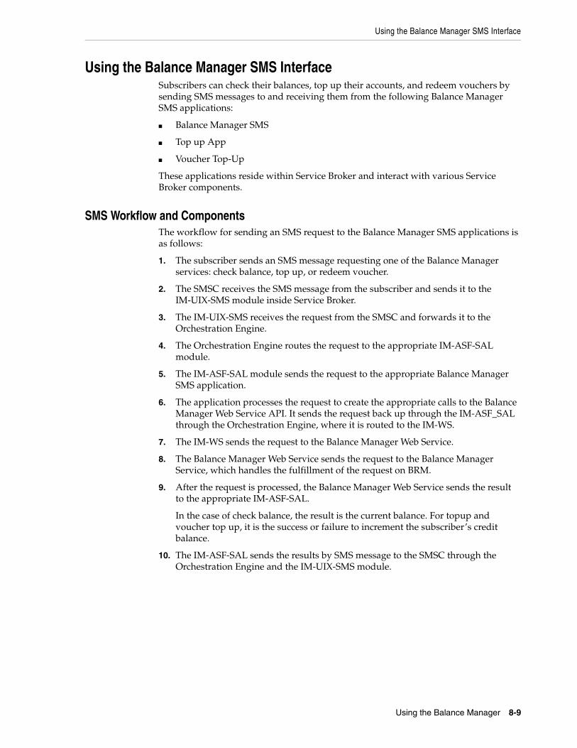
Using the Balance Manager SMS Interface
Using the Balance Manager 8-9
Using the Balance Manager SMS InterfaceSubscribers can check their balances, top up their accounts, and redeem vouchers by sending SMS messages to and receiving them from the following Balance Manager SMS applications:
■ Balance Manager SMS
■ Top up App
■ Voucher Top-Up
These applications reside within Service Broker and interact with various Service Broker components.
SMS Workflow and ComponentsThe workflow for sending an SMS request to the Balance Manager SMS applications is as follows:
1. The subscriber sends an SMS message requesting one of the Balance Manager services: check balance, top up, or redeem voucher.
2. The SMSC receives the SMS message from the subscriber and sends it to the IM-UIX-SMS module inside Service Broker.
3. The IM-UIX-SMS receives the request from the SMSC and forwards it to the Orchestration Engine.
4. The Orchestration Engine routes the request to the appropriate IM-ASF-SAL module.
5. The IM-ASF-SAL module sends the request to the appropriate Balance Manager SMS application.
6. The application processes the request to create the appropriate calls to the Balance Manager Web Service API. It sends the request back up through the IM-ASF_SAL through the Orchestration Engine, where it is routed to the IM-WS.
7. The IM-WS sends the request to the Balance Manager Web Service.
8. The Balance Manager Web Service sends the request to the Balance Manager Service, which handles the fulfillment of the request on BRM.
9. After the request is processed, the Balance Manager Web Service sends the result to the appropriate IM-ASF-SAL.
In the case of check balance, the result is the current balance. For topup and voucher top up, it is the success or failure to increment the subscriber’s credit balance.
10. The IM-ASF-SAL sends the results by SMS message to the SMSC through the Orchestration Engine and the IM-UIX-SMS module.
Using the Balance Manager SMS Interface
8-10 Online Mediation Controller Implementation Guide
Figure 8–3 SMS Workflow
SMS Configuration TasksThe SMS interface to the Balance Manager requires additional configuration of several Service Broker components in addition to the tasks described in the "Generic Set Up for the Balance Manager" section.
The following configuration tasks are required if you are using the Balance Manager SMS application. These tasks are all performed in the Service Broker Administration Console.
1. Add and configure two IM-UIX-SMS SMPP instances to process requests to and from the SMSC. See "Setting Up the IM-UIX-SMS Module" for details.
2. Configure the SMPP SSUs to set up routing of submit_sm and deliver_sm requests to the addresses of the three SMS applications. See "Configuring the SMPP Signaling Server Unit (SMPP SSU)" for details.

Using the Balance Manager SMS Interface
Using the Balance Manager 8-11
3. Create three IM-ASF-SAL instances, one for each application, to enable the applications to interact with the other Service Broker modules. See "Creating and Configuring the IM-ASF-SALs" for details.
4. Create an IM-WS instance for the Balance Manager. This enables the Balance Manager to receive messages from and send messages to Web Services using SOAP and REST interfaces. See "Creating and Configuring an IM-WS" for details.
5. Create an outgoing rule to define how the Web Services SSU routes outgoing Balance Manager messages. "Creating an Outgoing Routing Rule for the Web Services Signaling Service Unit (SSU)" for details.
6. Set up the orchestration logic, which tells the Orchestration Engine the order in which to invoke the applications. See "Setting Up the Orchestration Logic for Balance Manager" for details.
7. Configure the text of outgoing messages in the Balance Manager SMS application. See "Configuring the Balance Manager SMS Application Messages" for details.
Setting Up the IM-UIX-SMS ModuleThe SMS interface to the Balance Manager SMS applications requires two IM-UIXSMS-SMPP instances: one to receive requests from the SMSC and another to send responses to the SMSC. If these modules do not exist, you must create them.
To create an IM-UIX-SMSSMPP instance to handle SMS requests:
1. Expand the OCSB node.
2. Click the Lock and Edit icon.
3. Expand the Processing Tier node.
4. Expand the Interworking Modules node.
5. Click the IM Management item.
6. Click New.
7. From the Type menu, select IMUIXSMSSMPP34.
8. From the Version menu, select 2.0.0.0.
9. In the Name field, enter a name for the instance; for example: imsmpp_in.
10. Click OK.
11. Click the Commit icon to commit your changes.
Repeat this procedure to create another instance to handle responses; for example imsmpp_out.
Then configure both IM-UIX-SMSSMPP instances.
To configure an IM-UIX-SMSSMPP instance:
1. Expand the OCSB node.
2. Click the Lock and Edit icon.
3. Expand the Processing Tier node.
4. Expand the Interworking Modules node.
5. Select the instance that you want to configure.
Using the Balance Manager SMS Interface
8-12 Online Mediation Controller Implementation Guide
6. See the discussion of configuring IM-UIX-SMS in Oracle Communications Service Broker Processing Domain Configuration Guide for detailed instructions for configuring the IM-UIX-SMSSMPP instances.
7. Click Apply.
Configuring the SMPP Signaling Server Unit (SMPP SSU)The SMPP SSU provides Service Broker with access to the SMSC over SMPP.
In this module, configure:
■ three incoming routing rules, one for each application
■ an SMPP network entity
■ a connection to the SMSC
The incoming routing rule defines the IM-UIX-SMS instance to which the SMPP SSU routes deliver_sm messages from the SMSC.
To create the incoming routing rules:
1. Expand the OCSB node.
2. Click the Lock and Edit icon.
3. Expand the Signaling Tier node.
4. Click the SSU SMPP item.
5. Click the SSU SMPP tab.
6. Click the Incoming Routing Rules subtab.
7. For each of the three Balance Manager SMS applications, do the following:
a. Click New.
b. In the dialog box, provide a name for the incoming rule in the Name field; for example: CheckBalance, TopUp, VoucherTopUp.
c. In the SMPP Destination Address field, enter the IP address of the SMSC that you configured in the IFC as the incoming SMSC for the Balance Manager. This is the destination address to be used in deliver_sm messages to the application. The Balance Manager SMS applications have different IP addresses.
d. In the Service Type field, enter SMS.
e. In the Alias field, enter the value that you configured for the Default SMSC Alias field of the incoming IM-UIXSMSSMPP instance.
f. Click OK.
See the discussion of configuring incoming routing rules in the configuring SMPP sign in Oracle Communications Service Broker Signaling Domain Configuration Guide for more information.
The SMPP network entity defines the SMSC to which the SMPP SSU routes submit_sm messages generated by the IM-UIX-SMS.
To create the network entity:
1. Expand the OCSB node.
2. Click the Lock and Edit icon.
3. Expand the Signaling Tier node.
Using the Balance Manager SMS Interface
Using the Balance Manager 8-13
4. Click the SSU SMPP item.
5. Click the SSU SMPP tab.
6. Click the SMPP Network Entities subtab.
7. Click New.
8. See the discussion of configuring SMPP network entities in Oracle Communications Service Broker Signaling Domain Configuration Guide for instructions on configuring the network entity.
9. Click OK.
The connection to the SMSC specifies the IP address and port to connect to, as well as other connection parameters.
To configure a connection to the SMSC:
1. Expand the OCSB node.
2. Click the Lock and Edit icon.
3. Expand the Signaling Tier node.
4. Click the SSU SMPP item.
5. Click the SMPP tab.
6. See the discussion of setting up SMSC connections in Oracle Communications Service Broker Signaling Domain Configuration Guide for detailed instructions on setting up SMSC connections.
Creating and Configuring the IM-ASF-SALsAn IM-ASF-SAL enables the Balance Manager to interface with the other Service Broker components. Create three IM-ASF-SALs, one for each Balance Manager SMS application.
To create the IM-ASF-SALs:
1. Expand the OCSB node.
2. Click the Lock and Edit icon.
3. Expand the Processing Tier node.
4. Expand the Interworking Modules node.
5. Click IM Management.
6. For each of the three Balance Manager SMS applications, do the following:
a. Click New.
b. From the Type menu, select IMASFSAL.
c. From the Version menu, select 2.0.0.0.
d. In the Name field, enter a name for the instance; for example: imCheckBalance, imTopUp, imVoucherTopup.
e. Click OK.
To configure the Balance Manager IM-ASF-SALs:
1. Expand the OCSB node.
2. Expand the Processing Tier node.

Using the Balance Manager SMS Interface
8-14 Online Mediation Controller Implementation Guide
3. Expand the Interworking Modules node.
4. For each of the three Balance Manager SMS applications, do the following:
a. In the left panel of the console, select one of the IMASFSAL instances created for the Balance Manager SMS applications.
The configuration form for that IM-ASF-SAL appears in the right panel.
b. Click the Application Server tab.
c. In the SAL Application Address field, enter the appropriate SIP URI of the Service Broker application to which to connect this IM-ASF -SAL. The choices are: sip:[email protected], sip:[email protected], or sip:[email protected].
d. From the SAL Mode field, select INLINE.
e. Configure the fields in the Session Keep Alive and SAL tabs as appropriate for your installation.
For information on the fields in the Session Keep Alive and SAL tabs, see the discussion of configuring IM-ASF-SAL in Oracle Communications Service Broker Processing Domain Configuration Guide
f. Click Apply.
5. After you have configured all three Balance Manager SMS applications, commit your changes to save the configuration and deploy it to the managed servers.
Creating and Configuring an IM-WSThe IM-WS enables the Balance Manager to receive messages from and send messages to Web Services using Simple Object Access Protocol (SOAP).
To create the IM-WS:
1. Expand the OCSB node.
2. Click the Lock and Edit icon.
3. Expand the Processing Tier node.
4. Expand the Interworking Modules node.
5. Click IM Management.
6. Click New.
7. In the dialog box, select IMWS from the Type menu.
8. Select 2.0.0.0 for the version.
9. Assign a name to the instance; for example: imwsbalmgr.
10. Click OK.
11. Click the Commit icon to commit your changes.
To configure the IM-WS:
1. Expand the OCSB node.
2. Expand the Processing Tier node.
3. Expand the Interworking Modules node.
4. In the left panel, select the IMWS instance created for the Balance Manager.
The configuration form for that IMWS appears in the right panel.
Using the Balance Manager SMS Interface
Using the Balance Manager 8-15
5. Click the WebService tab.
6. In the Web Service Alias field, enter topup.
7. From the Web Service type menu, select SOAP.
8. In the Web Service Body Type field, enter topuprequest.
9. Click Apply.
Creating an Outgoing Routing Rule for the Web Services Signaling Service Unit (SSU)The outgoing routing rule for the Web Services SSU defines how messages are routed from the Balance Manager Service.
This task assumes that the network access point on which the Web Services SSU listens for HTTP traffic has been previously configured. See the discussion of configuring HTTP server network access settings in Oracle Communications Service Broker Signaling Domain Configuration Guide for more information.
To create an outgoing routing rule for the Web Services SSU:
1. Expand the OCSB node.
2. Click the Lock and Edit icon.
3. Expand the Signaling Tier node.
4. Expand the SSU Web Services node.
5. Click the General item.
6. Click the SSU WS tab.
7. Click the Outgoing Routing Rules subtab.
8. Click New.
9. In the Name field, assign a name to the rule.
10. In the Alias field, enter topup.
11. In the Web Service URI field, enter the URI of your Balance Manager Web Service in the form:
http://BalanceManagerWebServiceIPAddress:port/soap/BalanceManagerService
12. See the discussion of configuring routing rules for outgoing Web Services in Service Broker Signaling Domain Configuration Guide for information on configuring the remaining fields.
13. Click OK.
Setting Up the Orchestration Logic for Balance ManagerYou need to inform the Orchestration Engine of the order in which to invoke the Balance Manager components. The order is:
1. The message is sent from the IM-UIX-SMSSMPP module that receives incoming SMS messages from the SMSC to the appropriate IM-ASF-SAL module.
2. Normally, the message is sent from the IM-ASF-SAL module to the Balance Manager Web Service. However, if there is a problem with the request, no message is sent to the Balance Manager Web service.
Using the Balance Manager SMS Interface
8-16 Online Mediation Controller Implementation Guide
3. The message is sent from the IM-ASF-SAL module to the IM-UIX-SMSSMPP module that sends results MSM messages to the SMSC.
First, edit the orchestration logic in the Orchestration Engine and then update the subscribers’ orchestration logic with the new flow.
You can add the orchestration logic for the Balance Manager using Orchestration Studio user interface or you can define the Initial Filter Criteria directly in an ifc.xml file that you edit directly with a text editor. See Oracle Communications Service Broker Orchestration Studio User's Guide for information on setting up orchestration logic using either method.
The criteria in the ifc.xml file are based on the TO header and the MESSAGE method. To access the Balance Manager Web Service, use one or more of the following: getBalance, voucherTopup, topup.
The orchestration logic associated with a subscriber is stored as part of the subscriber profile. After you have updated ifc.xml for the Balance Manager components, incorporate it into the <ifcProfileData> element in the subscriber profile using the updateSubscriber operation. See the Subscriber Store API Reference in Oracle Communications Service Broker Subscriber Store User's Guide for information about this operation.
The IP addresses for the three applications in the ifc.xml file should be set to the same values as the IP addresses that you configured for the incoming routing rules in the SMPP SSU.
Configuring the Balance Manager SMS Application MessagesThis step configures the outgoing messages that will be displayed to the end user in response to requests to check a balance, top up an account from a credit card or bank account, or redeem a voucher.
To configure the Top up App application messages:
1. Expand the OCSB node.
2. Click the Lock and Edit icon.
3. Expand the Processing Tier node.
4. Expand the Applications node.
5. Click the Top up App item.
The Top up App configuration form appears in the right panel.
6. Click the Top up configuration tab.
7. In the Success Message field, enter the text for the message that the user will receive if the request succeeds.
The only information available to the application is whether the operation succeeded or failed.
8. In the Error Message field, enter the text for the message that the user will receive if the request fails.
9. In the Content parse field enter the regular expression to use to parse the incoming message.
The regular expression describes how the content is divided between the amount and the PIN. For top up, it should describe two groups of digits, one for the amount and one for the PIN. For example, (\d+\.?\d):(\d+) describes two groups, separated by a colon. The first group, representing the amount, contains any
Using the Balance Manager SMS Interface
Using the Balance Manager 8-17
number of digits followed by an optional dot followed by any number of digits. The second group, representing the PIN describes any number of digits
10. Click Apply.
To configure the Voucher Top-up application messages:
1. Expand the OCSB node.
2. Click the Lock and Edit icon.
3. Expand the Processing Tier node.
4. Expand the Applications node.
5. Click the Voucher Top-Up item.
The Voucher Top-Up configuration form appears in the right panel.
6. Click the Voucher Top up configuration tab.
7. In the Success Message field, enter the text for the message that the user will receive if the request succeeds.
The only information available to the application is whether the operation succeeded or failed.
8. In the Error Message field, enter the text for the message that the user will receive if the request fails.
9. In the Content parse field enter the regular expression to use to parse the incoming message.
The regular expression describes how the content is divided between the voucher number and the voucher PIN. For voucher redemption, it should describe two groups of digits, one for the voucher and one for the voucher PIN. For example, (\d+):(\d+) describes two groups of any number of consecutive digits separated by a colon.
10. Click Apply.
To configure the Balance Manager SMS application messages:
1. Expand the OCSB node.
2. Click the Lock and Edit icon.
3. Expand the Processing Tier node.
4. Expand the Applications node.
5. Expand the Balance Manager item.
6. Expand the SMS node.
7. Click the Check Balance item.
8. In the Success Message field, enter the text for the message that the user will receive if the request succeeds. You can use %s as the placeholder for the amount, which the Balance Manager will supply; for example, "Your new balance is %s".
9. In the Error Message field, enter the text for the message that the user will receive if the request fails.
10. In the Request SMS Format field, enter the regular expression to use to parse the incoming message.
The regular expression describes the part of the content that is the PIN. For example, \d+ describes any number of consecutive digits.
Using the Balance Manager Web Services API
8-18 Online Mediation Controller Implementation Guide
11. Click Apply.
Using the Balance Manager Web Services APIThe following Balance Manager Web Service APIs support the basic Balance Manager functionality through SOAP Web Services:
■ authenticate
■ getBalance
■ topUp
■ voucherTopup
The Balance Manager SOAP Web Service Definition Language (WSDL) file is by default located in:
http://host:port/soap/BalanceManagerService?wsdl
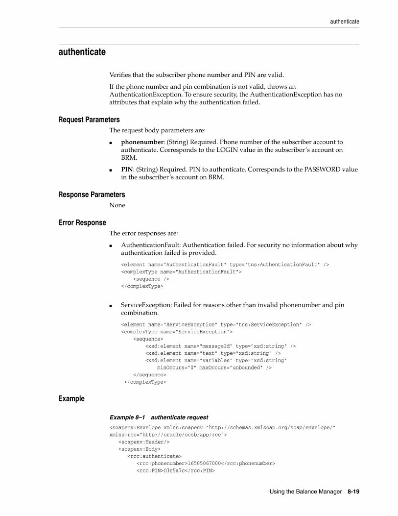
authenticate
Using the Balance Manager 8-19
authenticate
Verifies that the subscriber phone number and PIN are valid.
If the phone number and pin combination is not valid, throws an AuthenticationException. To ensure security, the AuthenticationException has no attributes that explain why the authentication failed.
8Request ParametersThe request body parameters are:
■ phonenumber: (String) Required. Phone number of the subscriber account to authenticate. Corresponds to the LOGIN value in the subscriber’s account on BRM.
■ PIN: (String) Required. PIN to authenticate. Corresponds to the PASSWORD value in the subscriber’s account on BRM.
8Response ParametersNone
8Error Response The error responses are:
■ AuthenticationFault: Authentication failed. For security no information about why authentication failed is provided.
<element name="AuthenticationFault" type="tns:AuthenticationFault" /><complexType name="AuthenticationFault"> <sequence /></complexType>
■ ServiceException: Failed for reasons other than invalid phonenumber and pin combination.
<element name="ServiceException" type="tns:ServiceException" /><complexType name="ServiceException"> <sequence> <xsd:element name="messageId" type="xsd:string" /> <xsd:element name="text" type="xsd:string" /> <xsd:element name="variables" type="xsd:string" minOccurs="0" maxOccurs="unbounded" /> </sequence> </complexType>
8Example
Example 8–1 authenticate request
<soapenv:Envelope xmlns:soapenv="http://schemas.xmlsoap.org/soap/envelope/" xmlns:rcc="http://oracle/ocsb/app/rcc"> <soapenv:Header/> <soapenv:Body> <rcc:authenticate> <rcc:phonenumber>16505067000</rcc:phonenumber> <rcc:PIN>O3r5a7c</rcc:PIN>

authenticate
8-20 Online Mediation Controller Implementation Guide
</rcc:authenticate> </soapenv:Body></soapenv:Envelope>
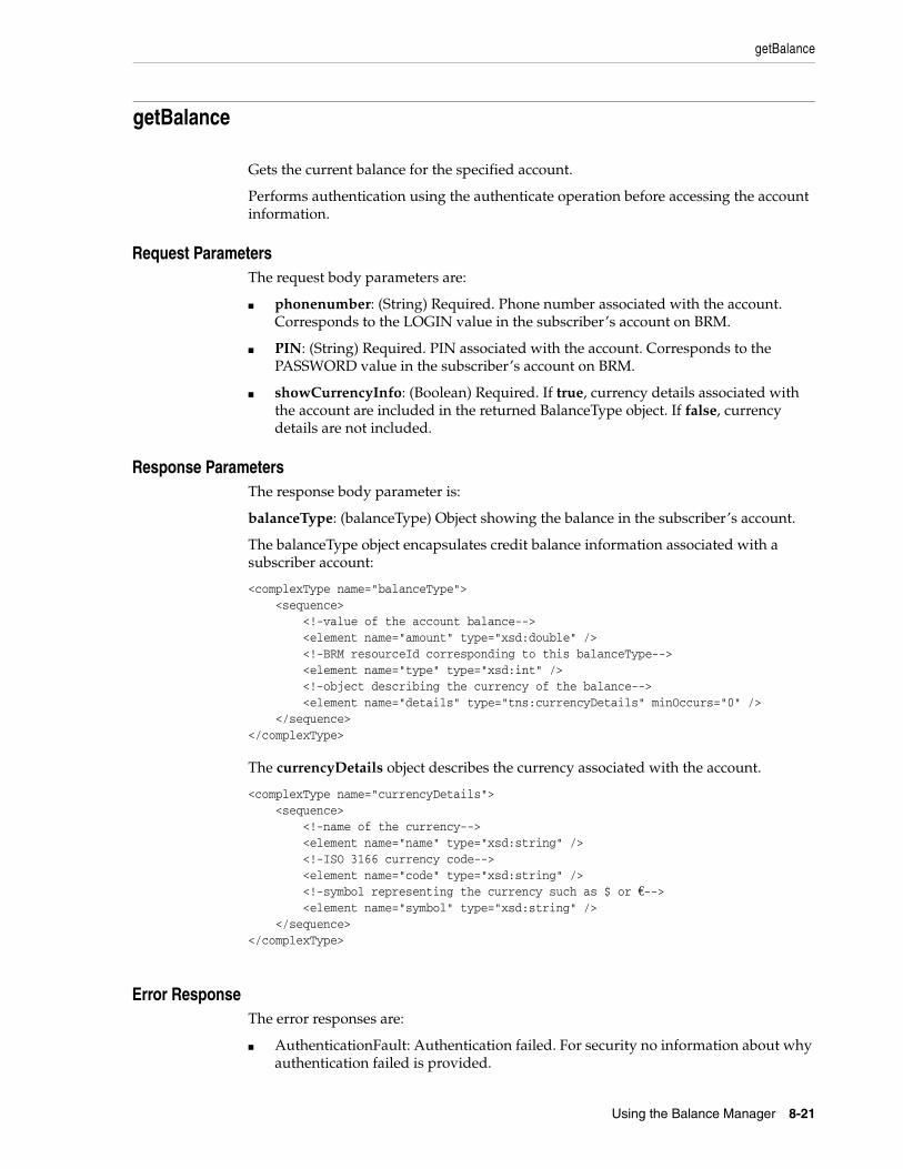
getBalance
Using the Balance Manager 8-21
getBalance
Gets the current balance for the specified account.
Performs authentication using the authenticate operation before accessing the account information.
8Request ParametersThe request body parameters are:
■ phonenumber: (String) Required. Phone number associated with the account. Corresponds to the LOGIN value in the subscriber’s account on BRM.
■ PIN: (String) Required. PIN associated with the account. Corresponds to the PASSWORD value in the subscriber’s account on BRM.
■ showCurrencyInfo: (Boolean) Required. If true, currency details associated with the account are included in the returned BalanceType object. If false, currency details are not included.
8Response ParametersThe response body parameter is:
balanceType: (balanceType) Object showing the balance in the subscriber’s account.
The balanceType object encapsulates credit balance information associated with a subscriber account:
<complexType name="balanceType"> <sequence> <!-value of the account balance--> <element name="amount" type="xsd:double" /> <!-BRM resourceId corresponding to this balanceType--> <element name="type" type="xsd:int" /> <!-object describing the currency of the balance--> <element name="details" type="tns:currencyDetails" minOccurs="0" /> </sequence></complexType>
The currencyDetails object describes the currency associated with the account.
<complexType name="currencyDetails"> <sequence> <!-name of the currency--> <element name="name" type="xsd:string" /> <!-ISO 3166 currency code--> <element name="code" type="xsd:string" /> <!-symbol representing the currency such as $ or €--> <element name="symbol" type="xsd:string" /> </sequence></complexType>
8Error Response The error responses are:
■ AuthenticationFault: Authentication failed. For security no information about why authentication failed is provided.
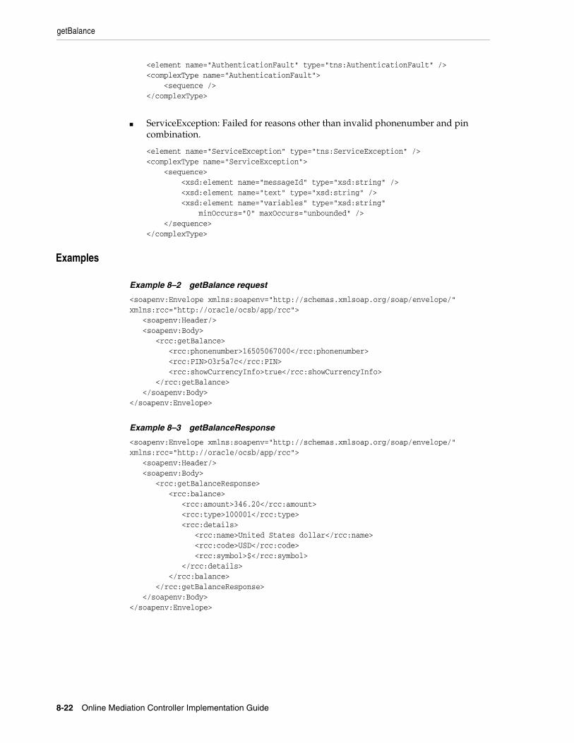
getBalance
8-22 Online Mediation Controller Implementation Guide
<element name="AuthenticationFault" type="tns:AuthenticationFault" /><complexType name="AuthenticationFault"> <sequence /></complexType>
■ ServiceException: Failed for reasons other than invalid phonenumber and pin combination.
<element name="ServiceException" type="tns:ServiceException" /><complexType name="ServiceException"> <sequence> <xsd:element name="messageId" type="xsd:string" /> <xsd:element name="text" type="xsd:string" /> <xsd:element name="variables" type="xsd:string" minOccurs="0" maxOccurs="unbounded" /> </sequence></complexType>
8Examples
Example 8–2 getBalance request
<soapenv:Envelope xmlns:soapenv="http://schemas.xmlsoap.org/soap/envelope/" xmlns:rcc="http://oracle/ocsb/app/rcc"> <soapenv:Header/> <soapenv:Body> <rcc:getBalance> <rcc:phonenumber>16505067000</rcc:phonenumber> <rcc:PIN>O3r5a7c</rcc:PIN> <rcc:showCurrencyInfo>true</rcc:showCurrencyInfo> </rcc:getBalance> </soapenv:Body></soapenv:Envelope>
Example 8–3 getBalanceResponse
<soapenv:Envelope xmlns:soapenv="http://schemas.xmlsoap.org/soap/envelope/" xmlns:rcc="http://oracle/ocsb/app/rcc"> <soapenv:Header/> <soapenv:Body> <rcc:getBalanceResponse> <rcc:balance> <rcc:amount>346.20</rcc:amount> <rcc:type>100001</rcc:type> <rcc:details> <rcc:name>United States dollar</rcc:name> <rcc:code>USD</rcc:code> <rcc:symbol>$</rcc:symbol> </rcc:details> </rcc:balance> </rcc:getBalanceResponse> </soapenv:Body></soapenv:Envelope>
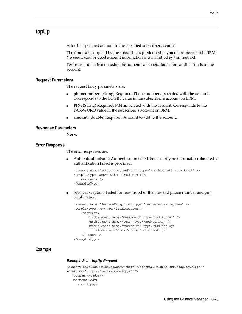
topUp
Using the Balance Manager 8-23
topUp
Adds the specified amount to the specified subscriber account.
The funds are supplied by the subscriber’s predefined payment arrangement in BRM. No credit card or debit account information is transmitted by this method.
Performs authentication using the authenticate operation before adding funds to the account.
8Request ParametersThe request body parameters are:
■ phonenumber: (String) Required. Phone number associated with the account. Corresponds to the LOGIN value in the subscriber’s account on BRM.
■ PIN: (String) Required. PIN associated with the account. Corresponds to the PASSWORD value in the subscriber’s account on BRM.
■ amount: (double) Required. Amount to add to the account.
8Response ParametersNone.
8Error Response The error responses are:
■ AuthenticationFault: Authentication failed. For security no information about why authentication failed is provided.
<element name="AuthenticationFault" type="tns:AuthenticationFault" /><complexType name="AuthenticationFault"> <sequence /></complexType>
■ ServiceException: Failed for reasons other than invalid phone number and pin combination.
<element name="ServiceException" type="tns:ServiceException" /><complexType name="ServiceException"> <sequence> <xsd:element name="messageId" type="xsd:string" /> <xsd:element name="text" type="xsd:string" /> <xsd:element name="variables" type="xsd:string" minOccurs="0" maxOccurs="unbounded" /> </sequence></complexType>
8Example
Example 8–4 topUp Request
<soapenv:Envelope xmlns:soapenv="http://schemas.xmlsoap.org/soap/envelope/" xmlns:rcc="http://oracle/ocsb/app/rcc"> <soapenv:Header/> <soapenv:Body> <rcc:topup>

topUp
8-24 Online Mediation Controller Implementation Guide
<rcc:phonenumber>16505067000</rcc:phonenumber> <rcc:PIN>O3r5a7c</rcc:PIN> <rcc:amount>100</rcc:amount> </rcc:topup> </soapenv:Body></soapenv:Envelope>

voucherTopup
Using the Balance Manager 8-25
voucherTopup
Redeems a voucher to add the voucher value to the specified subscriber account.
This operation does not perform authentication. Users can redeem a voucher to add funds to accounts that are not their own.
8Request ParametersThe request body parameters are:
■ phonenumber: (String) Required. Phone number associated with the account to which the voucher amount is added. Corresponds to the LOGIN value in the subscriber’s account on BRM.
■ voucherNumber: (String) Required. Number of the voucher.
■ voucherPin: (double) Required. PIN for the voucher.
8Response ParametersNone.
8Error Response The error response is:
■ ServiceException: Generic exception
<element name="ServiceException" type="tns:ServiceException" /><complexType name="ServiceException"> <sequence> <xsd:element name="messageId" type="xsd:string" /> <xsd:element name="text" type="xsd:string" /> <xsd:element name="variables" type="xsd:string" minOccurs="0" maxOccurs="unbounded" /> </sequence></complexType>
8Example
Example 8–5 voucherTopup request
<soapenv:Envelope xmlns:soapenv="http://schemas.xmlsoap.org/soap/envelope/" xmlns:rcc="http://oracle/ocsb/app/rcc"> <soapenv:Header/> <soapenv:Body> <rcc:voucherTopup> <rcc:phonenumber>16505067000</rcc:phonenumber> <rcc:vouchernumber>0020031003</rcc:vouchernumber> <rcc:voucherpin>6T3#e</rcc:voucherpin> </rcc:voucherTopup> </soapenv:Body></soapenv:Envelope>

voucherTopup
8-26 Online Mediation Controller Implementation Guide
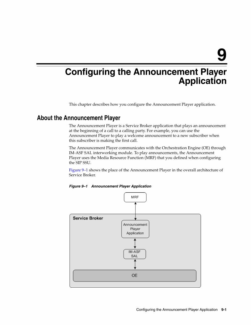
9
Configuring the Announcement Player Application 9-1
9Configuring the Announcement PlayerApplication
This chapter describes how you configure the Announcement Player application.
About the Announcement PlayerThe Announcement Player is a Service Broker application that plays an announcement at the beginning of a call to a calling party. For example, you can use the Announcement Player to play a welcome announcement to a new subscriber when this subscriber is making the first call.
The Announcement Player communicates with the Orchestration Engine (OE) through IM-ASF SAL interworking module. To play announcements, the Announcement Player uses the Media Resource Function (MRF) that you defined when configuring the SIP SSU.
Figure 9–1 shows the place of the Announcement Player in the overall architecture of Service Broker.
Figure 9–1 Announcement Player Application
Setting Up the Announcement Player
9-2 Online Mediation Controller Implementation Guide
Like any other application, the Announcement Player is a part of the orchestration flow. You need to configure the orchestration flow in a way that triggers the Announcement Player when the OE receives an INVITE message. After the Announcement Player has finished playing an announcement, the OE routes the session to the next application in the orchestration flow.
To allow the OE to trigger the Announcement Player, you need to perform the following steps:
1. Set up the instance of IM-ASF SAL and MRF. See "Setting Up the Announcement Player" for more information.
2. Specify the MRF alias and the code of the announcement to be played. See "Configuring the Announcement Player" for more information.
Setting Up the Announcement PlayerTo set up the Announcement Player:
1. Create an instance of IM-ASF SAL. See the "Managing Interworking Modules" chapter in Oracle Communications Service Broker Processing Domain Configuration Guide for more information.
2. In the Application Server tab, set the parameters as follows:
■ In the SAL Application Address field, type sip:[email protected].
■ From the SAL Mode list, select INLINE.
3. Specify configuration parameters on the Session Keep Alive and SAL tabs as required. See the "Configuring IM-ASF SAL" chapter in Oracle Communications Service Broker Processing Domain Configuration Guide for more information.
4. Using the Orchestration Studio, add the newly created instance of IM-ASF SAL to the orchestration flow. See the "Specifying IMs" section of the "Building an Orchestration Logic Flow" chapter in the Oracle Communications Service Broker Orchestration Studio User’s Guide for more information.
5. To trigger the Announcement Player when it receives an INVITE message, in the Orchestration Studio, add the condition for routing the session to the IM-ASF SAL and check whether the SIP Method is INVITE. See the "Adding Conditions" section of the "Building an Orchestration Logic Flow" chapter in the Oracle Communications Service Broker Orchestration Studio User’s Guide for more information.
6. Using the SIP Network Entities tab in the SSU SIP configuration screen, specify the alias and the physical address of the MRF that the Announcement Player uses. See the "Configuring SIP Network Entities" section of the "Configuring SIP Signaling Server Units " chapter in the Oracle Communications Service Broker Signaling Domain Configuration Guide for more information.
Configuring the Announcement PlayerTo configure the Announcement Player:
1. In the navigation tree, expand the OCSB node.
2. Expand the Processing Tier node.
3. Expand the Applications node.

Configuring the Announcement Player
Configuring the Announcement Player Application 9-3
4. Select the Announcement Player node.
5. In the mrf-alias field, enter the alias of the MRF that the Announcement Player should trigger to play the announcement.
This alias must correspond to the alias that you defined when configuring SIP network entities in the SIP SSU. See the "Configuring SIP Network Entities" section of the "Configuring SIP Signaling Server Units " chapter in the Oracle Communications Service Broker Signaling Domain Configuration Guide for more information.
6. In the announcement-code field, enter the code of the announcement that the MRF should play.
7. Click Apply.

Configuring the Announcement Player
9-4 Online Mediation Controller Implementation Guide
10
Configuring the Home Zones Application 10-1
10Configuring the Home Zones Application
This chapter describes how you configure the Home Zones application.
About Network ZoningYou can apply different rates or service access conditions depending on the current location of a mobile subscriber. For example, you can charge a minimum rate when a subscriber is located at home and apply a higher rate when the subscriber is calling from abroad.
Service Broker recognizes several areas that represent various locations of a subscriber. These areas are called network zones:
■ Home zone
This is an area of a network in which a subscriber is registered. For example, a home zone might be an area closest to a subscriber’s residence. You define a subscriber’s home zone as a part of the subscriber’s profile. See "Defining a Home Zone" for more information.
■ Home network
This is an entire network in which a subscriber is registered. You define a home network using the Home Zones application. See "Defining the Home Network" for more information.
■ Roaming
If a subscriber is not located in either home network or home zone, this subscriber is considered located in a roaming zone.
About Configuration of Network ZonesYou define a home zone and home network for each subscriber. The process of defining these zones requires specifying the following criteria:
■ Access protocols (such as IEEE-802.11a, 3GPP-GERAN, or 3GPP-UTRAN-FDD). These are the protocols that the subscriber uses to access the network. You can define multiple protocols to handle situations when a subscriber transfers different types of data (for example, voice, short messages, and multimedia) from the same cell.
■ Cell identity parameter for each protocol that you defined. A cell identity parameter contains IDs of cells that use the specified access protocol. This parameter varies depending on the access protocol. For example, if you specified that the access protocol is IEEE-802.11a, the call identity parameter can be
About the Home Zones Application
10-2 Online Mediation Controller Implementation Guide
cgi-3gpp. Similarly, if the access protocol is 3GPP-GERAN, the call identity parameter can be gsm-location-number. See 3GPP TS 24.229 for more information.
■ IDs of home network cells. You set the cell identity parameter to IDs of cells in which the specified network access protocol is used.
About the Home Zones ApplicationThe information about the network zone in which the subscriber is currently located is transferred to Service Broker in the P-Access-Network-Info header of a message that the subscriber sends.
The Home Zones application is a Service Broker application that checks this header and identifies whether a mobile subscriber is in the home zone, home network, or roaming.
Depending on the zone, the application adds to the session a custom header, x-wcs-location, and sets it accordingly. Other applications can use the value of this header and implement various scenarios. For example, if a subscriber is in the home zone, a charging application can apply a special rate.
After the Home Zones application receives a message, the application does the following:
1. The Home Zones application retrieves the subscriber’s profile from the Subscriber Store to check whether the information set in the P-Access-Network-Info header of the message matches the settings that define the home zone of the subscriber.
2. If the P-Access-Network-Info header matches these settings, the Home Zones application adds the x-wcs-location header to the message and sets this header to "homezone".
3. Otherwise, the Home Zones application checks whether the P-Access-Network-Info header of the message matches the settings that define the home network.
4. If the P-Access-Network-Info header matches these settings, the Home Zones application adds the x-wcs-location header to the message and sets this header to "home network".
5. Otherwise, the Home Zones application adds the x-wcs-location header to the message and sets this header to "roaming".
The Home Zones application communicates with the OE through IM-ASF SAL interworking module.
Figure 10–1 shows the place of the Home Zones application in the overall architecture of Service Broker.
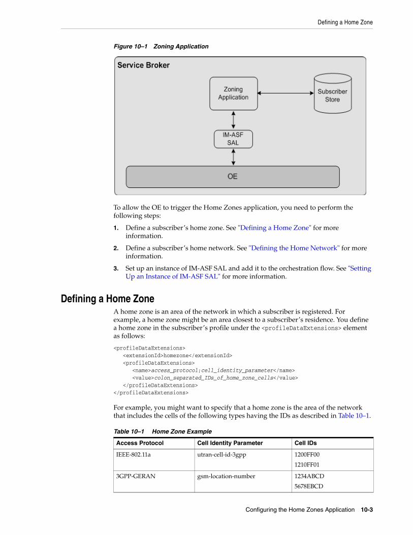
Defining a Home Zone
Configuring the Home Zones Application 10-3
Figure 10–1 Zoning Application
To allow the OE to trigger the Home Zones application, you need to perform the following steps:
1. Define a subscriber’s home zone. See "Defining a Home Zone" for more information.
2. Define a subscriber’s home network. See "Defining the Home Network" for more information.
3. Set up an instance of IM-ASF SAL and add it to the orchestration flow. See "Setting Up an Instance of IM-ASF SAL" for more information.
Defining a Home ZoneA home zone is an area of the network in which a subscriber is registered. For example, a home zone might be an area closest to a subscriber’s residence. You define a home zone in the subscriber’s profile under the <profileDataExtensions> element as follows:
<profileDataExtensions> <extensionId>homezone</extensionId> <profileDataExtensions> <name>access_protocol;cell_identity_parameter</name> <value>colon_separated_IDs_of_home_zone_cells</value> </profileDataExtensions></profileDataExtensions>
For example, you might want to specify that a home zone is the area of the network that includes the cells of the following types having the IDs as described in Table 10–1.
Table 10–1 Home Zone Example
Access Protocol Cell Identity Parameter Cell IDs
IEEE-802.11a utran-cell-id-3gpp 1200FF00
1210FF01
3GPP-GERAN gsm-location-number 1234ABCD
5678EBCD
Defining the Home Network
10-4 Online Mediation Controller Implementation Guide
To reflect this configuration in a subscriber’s profile, you need to set up the <profileDataExtensions> element as follows:
<profileDataExtensions> <extensionId>homenetwork</extensionId> <profileDataExtensions> <name>IEEE-802.11a;utran-cell-id-3gpp</name> <value>1200FF00;1210FF01</value> </profileDataExtensions> <profileDataExtensions> <name>3GPP-GERAN;gsm-location-number</name> <value>1234ABCD;5678EBCD</value> </profileDataExtensions></profileDataExtensions>
You create and update subscriber profiles using the Subscriber Provisioning API. See the "Subscriber Provisioning API Reference" chapter in Oracle Communications Service Broker Subscriber Store User's Guide.
Defining the Home NetworkYou can define the home network using the Administration Console. The configuration includes specifying access protocols and cell identity parameters for the home network as well as IDs of cells that the home network includes.
Specifying Access Protocols and Cell Identity ParametersTo specify access protocols and cell identity parameters:
1. In the navigation tree, expand the OCSB node.
2. Expand the Processing Tier node.
3. Expand the Applications node.
4. Select the Home Zones node.
5. Click the Home Network Cell Types tab.
6. Click New.
The New dialog box appears.
7. In the Access Type field, enter the name of the network access protocol used in the cell. For example, you can set Access Type to IEEE-802.11a.
See 3GPP TS 24.229 for the list of allowed values.
8. In the Access Information field, enter the name of the cell identity parameter according to the network access protocol. For example, you can set Access Information to utran-cell-id-3gpp.
See 3GPP TS 24.229 for the list of allowed values.
You use this parameter to specify IDs of network cells in which the specified network access protocol is used. See "Specifying IDs of Home Network Cells" for more information.
9. Click OK.
Specifying IDs of Home Network CellsTo specify IDs of home network cells:

Setting Up an Instance of IM-ASF SAL
Configuring the Home Zones Application 10-5
1. In the navigation tree, expand the OCSB node.
2. Expand the Processing Tier node.
3. Expand the Applications node.
4. Select the Home Zones node.
5. Click the Home Network Cell Values tab.
6. In the Parent list, select the cell whose ID you want to define.
7. Click New.
The New dialog box appears.
8. In the Value Data field, enter an ID of the cell.
9. Click OK.
Setting Up an Instance of IM-ASF SALTo set up an instance of IM-ASF SAL:
1. Create an instance of IM-ASF SAL. See the "Managing Interworking Modules" chapter in Oracle Communications Service Broker Processing Domain Configuration Guide for more information.
2. In the Application Server tab, set the parameters as follows:
■ In the SAL Application Address field, type sip:[email protected].
■ From the SAL Mode list, select INLINE.
3. Specify configuration parameters on the Session Keep Alive and SAL tabs as required. See the "Configuring IM-ASF SAL" chapter in Oracle Communications Service Broker Processing Domain Configuration Guide for more information.
4. Specify configuration parameters of the created instance of IM-ASF SAL to make it communicate with the Home Zones application. See the "Configuring IM-ASF SAL" chapter in Oracle Communications Service Broker Processing Domain Configuration Guide for more information.
5. Using the Orchestration Studio, do the following:
a. Add the instance of IM-ASF SAL that communicates with the Home Zones application to the orchestration flow. See the "Specifying IMs" section of the "Building an Orchestration Logic Flow" chapter in Oracle Communications Service Broker Orchestration Studio User’s Guide for more information.
b. If necessary, specify conditions that the session must meet to be routed to the instance of IM-ASF SAL. See the "Adding Conditions" section of the "Building an Orchestration Logic Flow" chapter in Oracle Communications Service Broker Orchestration Studio User’s Guide for more information.
c. To trigger other applications based on the value of the x-wcs-location header, add conditions for routing the session to different IMs and check whether the x-wcs-location is "homezone", "home network", or "roaming". See the "Adding Conditions" section of the "Building an Orchestration Logic Flow" chapter in Oracle Communications Service Broker Orchestration Studio User’s Guide for more information.

Setting Up an Instance of IM-ASF SAL
10-6 Online Mediation Controller Implementation Guide
11
Configuring the Threshold Notification Application 11-1
11Configuring the Threshold NotificationApplication
This chapter describes how you configure the Threshold Notification application.
About Threshold RulesA threshold is a value of a Diameter Attribute-Value Pair (AVP) that triggers Service Broker to generate an event. Other applications can subscribe to this event and perform various actions when the event occurs.
For example, you can define that if a subscriber reaches a requested time quota, Service Broker generates an event that triggers an application to send to the subscriber an SMS notification.
You define thresholds for each subscriber by creating threshold rules. A threshold rule is a set of conditions that specify the following:
■ An AVP to be checked. Currently, Threshold Notification checks the CC-TIME AVP only
■ Threshold value of the CC-TIME AVP
■ Whether Service Broker applies the rule every time the threshold is reached
■ Whether Service Broker should apply the rule only when the subscriber is in roaming
You define threshold rules in a subscriber’s profile.
About Threshold NotificationThreshold Notification is a Service Broker application that compares threshold rules of a subscriber with the units that the subscriber actually used. If Threshold Notification finds that conditions of a threshold rule are met, Threshold Notification generates an event.
Threshold Notification communicates with the OE through IM-ASF SAL interworking module.
Threshold Notification works as follows:
1. Network-facing interworking modules (IMs), such as IM-SCF, R-IM-OCF, or R-IM-ASF, add information about used units and units to be requested to the ChargingInfo header of the message.
About Threshold Notification
11-2 Online Mediation Controller Implementation Guide
2. The Orchestration Engine (OE) communicates with the Subscriber Store to retrieve threshold rules from the subscriber profile. The OE adds these rules to the body of the message.
3. The OE forwards the session to IM-OCF. Based on the ChargingInfo header, IM-OCF generates a CCR and sends it to the online charging application.
4. The online charging application responds to IM-OCF with a Credit Control Answer (CCA). In this CCA, the online charging application specifies how many units are granted.
5. Based on the CCA, IM-OCF updates the ChargingInfo header by adding the amount of granted units.
6. The OE forwards the session to Threshold Notification.
To allow Threshold Notification to receive updated charging information, the OE must always route a session to Threshold Notification after IM-OCF. To achieve this, you need to form IM-OCF and Threshold Notification into a unidirectional group (see the "Defining the Orchestration Order of Messages Sent by a Called Party" section of the "Invoking Applications Based on the Previous Session Route" chapter in Oracle Communications Service Broker Orchestration Studio User’s Guide for more information about unidirectional groups).
7. Threshold Notification compares the information stored in the ChargingInfo header added by the network-facing modules with the threshold rules added by the OE. When Threshold Notification application finds a match between threshold rules and the information in the ChargingInfo header, Threshold Notification generates an event and submits it to Event Processor.
See "Using the Event Notification API" for more information about how applications can consume events and run their own business logic in the occurrence of these events.
Figure 11–1 shows the place of the Threshold Notification application in the overall architecture of Service Broker.
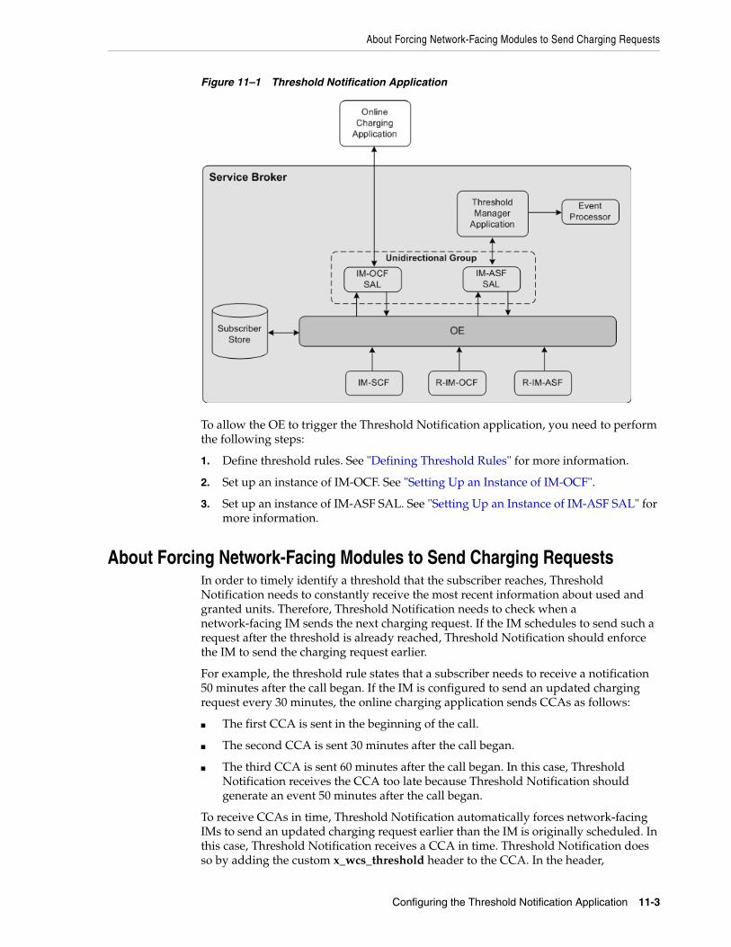
About Forcing Network-Facing Modules to Send Charging Requests
Configuring the Threshold Notification Application 11-3
Figure 11–1 Threshold Notification Application
To allow the OE to trigger the Threshold Notification application, you need to perform the following steps:
1. Define threshold rules. See "Defining Threshold Rules" for more information.
2. Set up an instance of IM-OCF. See "Setting Up an Instance of IM-OCF".
3. Set up an instance of IM-ASF SAL. See "Setting Up an Instance of IM-ASF SAL" for more information.
About Forcing Network-Facing Modules to Send Charging RequestsIn order to timely identify a threshold that the subscriber reaches, Threshold Notification needs to constantly receive the most recent information about used and granted units. Therefore, Threshold Notification needs to check when a network-facing IM sends the next charging request. If the IM schedules to send such a request after the threshold is already reached, Threshold Notification should enforce the IM to send the charging request earlier.
For example, the threshold rule states that a subscriber needs to receive a notification 50 minutes after the call began. If the IM is configured to send an updated charging request every 30 minutes, the online charging application sends CCAs as follows:
■ The first CCA is sent in the beginning of the call.
■ The second CCA is sent 30 minutes after the call began.
■ The third CCA is sent 60 minutes after the call began. In this case, Threshold Notification receives the CCA too late because Threshold Notification should generate an event 50 minutes after the call began.
To receive CCAs in time, Threshold Notification automatically forces network-facing IMs to send an updated charging request earlier than the IM is originally scheduled. In this case, Threshold Notification receives a CCA in time. Threshold Notification does so by adding the custom x_wcs_threshold header to the CCA. In the header,
Defining Threshold Rules
11-4 Online Mediation Controller Implementation Guide
Threshold Notification specifies how much time in advance, in minutes, the IM should send the next request before the threshold is reached. In the example described above, Threshold Notification should add the x_wcs_threshold header to the second CCA and set this header to 10 minutes. This enforces the IM to send the IM the next request 50 minutes after the call began.
Defining Threshold RulesYou define threshold rules in the subscriber’s profile under the <profileDataExtensions> element as follows:
<extensions> <extension> <id>session-threshold</id> <field key="threshold_rule_name" value="AVP;Threshold_Value;IsRecurring;IsRoamingOnly"/> </extension></extensions>
For example, you might want to define two rules that trigger the Threshold Notification application to generate an event when the following occurs:
■ Rule 1:
■ The subscriber used 25 minutes
■ Service Broker applies the rule every time the threshold is reached
■ Whether or not the subscriber is in roaming, Service Broker always applies this rule
■ Rule 2:
■ The subscriber used 10 minutes
■ Service Broker applies the rule only once
■ Service Broker applies this rule only when the subscriber is in roaming
To reflect this configuration in a subscriber’s profile, you need to set up the <profileDataExtensions> element as follows:
<extensions> <extension> <id>session-threshold</id> <field key="threshold1" value="CC_TIME;25;true;false"/> <field key="threshold2" value="CC_TIME;10;true;true"/> </extension></extensions>
You create and update subscriber profiles using the Subscriber Provisioning API. See the "Subscriber Provisioning API Reference" chapter in Oracle Communications Service Broker Subscriber Store User's Guide.
Setting Up an Instance of IM-OCFTo set up an instance of IM-OCF:
1. Create an instance of IM-OCF. See the "Managing Interworking Modules" chapter in Oracle Communications Service Broker Processing Domain Configuration Guide for more information.

Setting Up an Instance of IM-ASF SAL
Configuring the Threshold Notification Application 11-5
2. Configure the instance of IM-OCF as required. See the "Configuring IM-OCF" chapter in Oracle Communications Service Broker Processing Domain Configuration Guide for more information.
3. Using the Orchestration Studio, do the following:
a. Add the instance of IM-OCF to the orchestration flow. See the "Specifying IMs" section of the "Building an Orchestration Logic Flow" chapter in Oracle Communications Service Broker Orchestration Studio User’s Guide for more information.
b. If necessary, specify conditions that the session must meet to be routed to the instance of IM-OCF. See the "Adding Conditions" section of the "Building an Orchestration Logic Flow" chapter in Oracle Communications Service Broker Orchestration Studio User’s Guide for more information.
Setting Up an Instance of IM-ASF SALTo set up an instance of IM-ASF SAL:
1. Create an instance of IM-ASF SAL. See the "Managing Interworking Modules" chapter in Oracle Communications Service Broker Processing Domain Configuration Guide for more information.
2. In the Application Server tab, set the parameters as follows:
■ In the SAL Application Address field, type sip:[email protected].
■ From the SAL Mode list, select INLINE.
3. Specify configuration parameters on the Session Keep Alive and SAL tabs as required. See the "Configuring IM-ASF SAL" chapter in Oracle Communications Service Broker Processing Domain Configuration Guide for more information.
4. Using the Orchestration Studio, do the following:
a. Add the instance of IM-ASF SAL that communicates with the Threshold application to the orchestration flow. See the "Specifying IMs" section of the "Building an Orchestration Logic Flow" chapter in Oracle Communications Service Broker Orchestration Studio User’s Guide for more information.
b. Create a flow in which the OE routes a session first to IM-OCF and then to IM-ASF SAL. See the "Building an Orchestration Logic Flow" chapter in Oracle Communications Service Broker Orchestration Studio User’s Guide for more information.
c. Add the instance of IM-OCF and IM-ASF SAL into a unidirectional group. See the "Defining the Orchestration Order of Messages Sent by a Called Party" section of the "Invoking Applications Based on the Previous Session Route" chapter in Oracle Communications Service Broker Orchestration Studio User’s Guide for more information.
d. If necessary, specify conditions that the session must meet to be routed to the instance of IM-ASF SAL. See the "Adding Conditions" section of the "Building an Orchestration Logic Flow" chapter in Oracle Communications Service Broker Orchestration Studio User’s Guide for more information.

Setting Up an Instance of IM-ASF SAL
11-6 Online Mediation Controller Implementation Guide
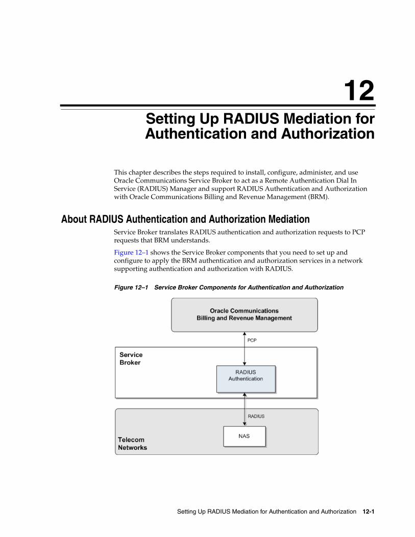
12
Setting Up RADIUS Mediation for Authentication and Authorization 12-1
12Setting Up RADIUS Mediation forAuthentication and Authorization
This chapter describes the steps required to install, configure, administer, and use Oracle Communications Service Broker to act as a Remote Authentication Dial In Service (RADIUS) Manager and support RADIUS Authentication and Authorization with Oracle Communications Billing and Revenue Management (BRM).
About RADIUS Authentication and Authorization MediationService Broker translates RADIUS authentication and authorization requests to PCP requests that BRM understands.
Figure 12–1 shows the Service Broker components that you need to set up and configure to apply the BRM authentication and authorization services in a network supporting authentication and authorization with RADIUS.
Figure 12–1 Service Broker Components for Authentication and Authorization
Configuring RADIUS Authentication and Authorization
12-2 Online Mediation Controller Implementation Guide
Configuring RADIUS Authentication and AuthorizationTo set up Service Broker to perform RADIUS Authentication and Authorization mediation to PCP, you need to configure the following Service Broker components:
■ RADIUS SSU
■ RADIUS PCP SSU
■ RADUIS Authentication module
Performing RADIUS Authentication and AuthorizationSee Oracle Communications Billing and Revenue Management RADIUS Manager for information on how authentication and authorization is done in BRM.
Configuration WorkflowTo create an end-to-end configuration for RADUIS authentication and authorization:
1. Configure the RADIUS SSU. See "Configuring the RADIUS SSU".
2. Create a set of client profiles and AVP filters for requests and responses. See "Configuring a Client Profile and AVP Filters".
3. Create a set of Proxy Realms. See "Adding Proxy Realms".
4. Add service mappings to define how RADIUS services are mapped to BRM service codes. See "Configuring RADIUS Mediation".
5. Configure the PCP SSU to connect to BRM. See "Connecting to BRM Through PCP".
Configuring the RADIUS SSUConfigure the RADIUS SSU as described in “Configuring the RADIUS SSU” Oracle Communications Service Broker Signaling Domain Configuration Guide. Use the following configuration data, specifically:
1. Create a new incoming routing rule.
2. Set Local Realm to any. This is a case-sensitive field.
3. Set Alias to anything. This is a mandatory field in the configuration but it is not used in the authentication and authorization use case. These requests are always routed to the RADIUS authentication and authorization module.
Configuring a Client Profile and AVP FiltersTo create a client profile:
1. In the RADIUS SSU Configuration screen, click the RADIUS tab and then the Client Profile tab, and then the ClientProfile sub tab to define the NAS client profile properties.
2. Click New.
3. In the New window enter:
In the Client Address field, enter the address or address range for the NAS client to configure. You can define a single IP address or host name, or a group if entered as a regular expression.
Configuration Workflow
Setting Up RADIUS Mediation for Authentication and Authorization 12-3
In the Client NAS Identifier field, enter the ID of the client network authentication server (NAS). This can be a fully qualified domain name.
In the Authentication Shared Secret Key field, enter the key in the credential store that maps to the secret in the credential store that is used to identify authentication requests from the NAS client. For more information about the credential store, see Oracle Communications Service Broker System Administrator's Guide.
In the accountingSharedSecretKey field, enter the key in the credential store that maps to the secret in the credential store that is used to identify accounting requests from the NAS client.
4. Click OK.
5. Click the Avps to copy from Request to Response tab.
6. Choose the client profile to apply the filter to from the Parent drop-down list. The index of the client profile correlates to the keyId assigned to the client profile.
7. Repeat for each AVP that is present in an incoming request and shall be included in the response:
1. Click New.
2. In the New: window enter:
In the Service field, enter the service ID for an AVP than is included in the request and shall be included in the response.
3. Click OK.
8. Click OK.
Adding Proxy RealmsTo a add a proxy realm to proxy requests to:
1. In the RADIUS SSU Configuration screen, click the RADIUS tab and then the Proxy Realm tab.
2. Click New.
3. In the New window enter:
In the Name of the proxy realm field, enter a symbolic name for the RADIUS server to proxy requests to.
In the UsernameMatch Criteria field, enter the user name matching criteria. Enter it as regular expression that matches the realm part of the User-Name attribute in the request. For example, enter isp1.net for any user that belongs to isp1.net.
In the Authentication Shared Secret Key field, enter a shared secret key used for authentication requests from the NAS client.
In the Authentication Shared Secret Key field, enter the key in the credential store that maps to the secret in the credential store that is used to identify authentication requests from the NAS client. For more information about the credential store, see Oracle Communications Service Broker System Administrator's Guide.
In the Accounting Shared Secret Key field, enter the key in the credential store that maps to the secret in the credential store that is used to identify accounting requests from the NAS client.
In the Request Timeout field, enter the number of seconds to wait for a response time before a request is considered to have timed out and the request is retried.
Configuring RADIUS Mediation
12-4 Online Mediation Controller Implementation Guide
In the Number of Retries field, enter the number of times to retry to forward a request before it is considered to have failed.
4. Click OK.
Connecting to BRM Through PCPTo connect Service Broker to Oracle Communications BRM:
1. Create BRM connection pools in the PCP SSU, as described in "Defining Connection Pools" in the chapter "Configuring the PCP Signaling Server Unit" in Oracle Communications Service Broker Signaling Domain Configuration Guide.
See also "About Connection Pooling" in Oracle Communications Billing and Revenue Management System Administrator’s Guide.
2. Secure the BRM connection pools that you created in step 1, as described in "Securing Connection Pools" in the chapter "Configuring the PCP Signaling Server Unit" in Oracle Communications Service Broker Signaling Domain Configuration Guide.
In the Administration Console:
a. In the navigation tree, expand the OCSB node, and then the Signaling Tier node.
b. Select the SSU PCP node.
c. In the PCP tab, select the Credential Store tab.
d. In the Password area, in the Key field, enter the ID of the connection pool that you want to secure. This should be the Pool ID that you assigned to the connection pool when you created the connection pool in step 1.
e. In the Password area, in the Password field, enter the password of the Oracle Communications BRM client application account used by the connection pool to access the BRM. This should be the password of the account that you configured in the BRM CM Login ID field when you initially defined the connection pool.
f. In the Password area, uncheck the one-way checkbox.
g. In the Password area, click the Set Password button.
h. Repeat steps d through d for each connection pool that you want to secure.
3. Define destination BRM applications, as described in "Defining PCP Network Entities" in the chapter "Configuring the PCP Signaling Server Unit" in Oracle Communications Service Broker Signaling Domain Configuration Guide.
Configuring RADIUS MediationThis section describes how to configure RADUIS Mediation using the Service Broker Administration Console.
To access the RADIUS Mediation Configuration screen:
1. In the domain navigation pane, expand OCSB.
2. Expand Processing Tier.
3. Click RADIUS Mediation.
The Radius Mediation configuration pane contains the subtabs described in Table 12–1.
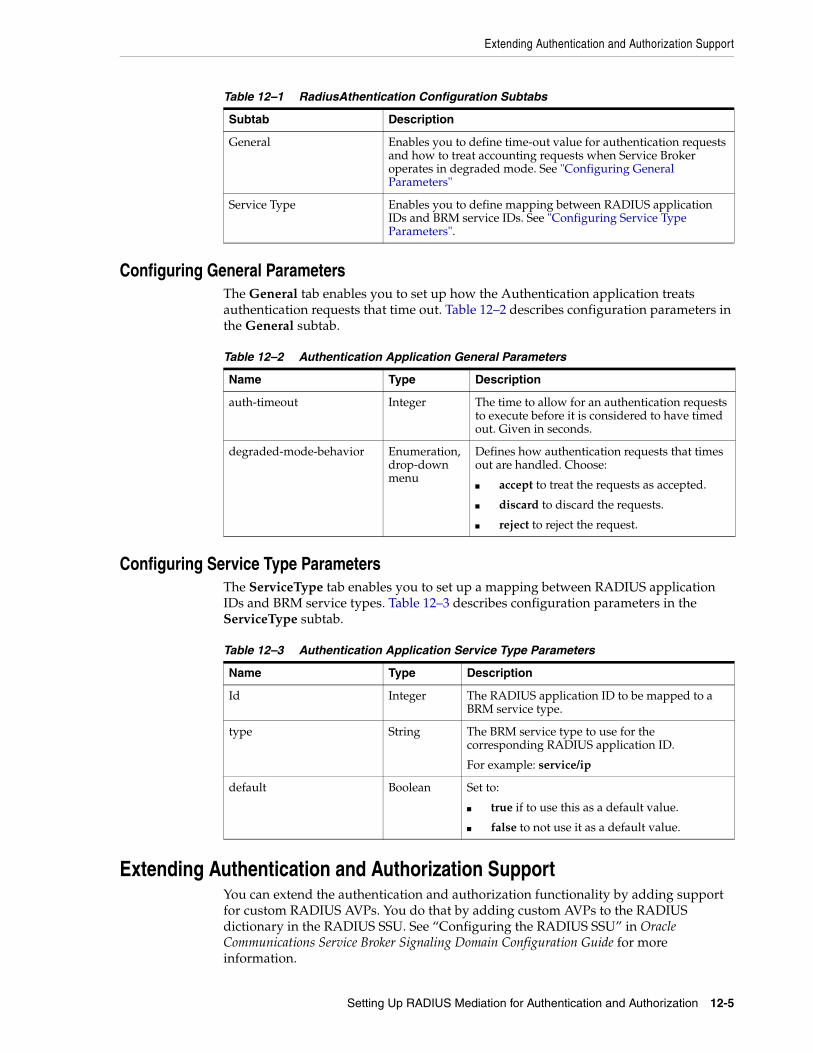
Extending Authentication and Authorization Support
Setting Up RADIUS Mediation for Authentication and Authorization 12-5
Configuring General ParametersThe General tab enables you to set up how the Authentication application treats authentication requests that time out. Table 12–2 describes configuration parameters in the General subtab.
Configuring Service Type ParametersThe ServiceType tab enables you to set up a mapping between RADIUS application IDs and BRM service types. Table 12–3 describes configuration parameters in the ServiceType subtab.
Extending Authentication and Authorization SupportYou can extend the authentication and authorization functionality by adding support for custom RADIUS AVPs. You do that by adding custom AVPs to the RADIUS dictionary in the RADIUS SSU. See “Configuring the RADIUS SSU” in Oracle Communications Service Broker Signaling Domain Configuration Guide for more information.
Table 12–1 RadiusAthentication Configuration Subtabs
Subtab Description
General Enables you to define time-out value for authentication requests and how to treat accounting requests when Service Broker operates in degraded mode. See "Configuring General Parameters"
Service Type Enables you to define mapping between RADIUS application IDs and BRM service IDs. See "Configuring Service Type Parameters".
Table 12–2 Authentication Application General Parameters
Name Type Description
auth-timeout Integer The time to allow for an authentication requests to execute before it is considered to have timed out. Given in seconds.
degraded-mode-behavior Enumeration, drop-down menu
Defines how authentication requests that times out are handled. Choose:
■ accept to treat the requests as accepted.
■ discard to discard the requests.
■ reject to reject the request.
Table 12–3 Authentication Application Service Type Parameters
Name Type Description
Id Integer The RADIUS application ID to be mapped to a BRM service type.
type String The BRM service type to use for the corresponding RADIUS application ID.
For example: service/ip
default Boolean Set to:
■ true if to use this as a default value.
■ false to not use it as a default value.

Extending Authentication and Authorization Support
12-6 Online Mediation Controller Implementation Guide


![Gateway Documentation - Broker Service Oracle FLEXCUBE ... · Gateway Documentation - Broker Service Oracle FLEXCUBE Universal Banking Release FCUBS_12.0.3.0.0 [April] [2014]](https://img.pdfslide.net/doc/110x75/5adf6f4d7f8b9ac0428c2a19/gateway-documentation-broker-service-oracle-flexcube-documentation-broker.jpg)