Embed Size (px)
Citation preview

Oracle FS1-2 Flash Storage System
Customer Service Guide
Part Number E41587-04Oracle FS1-2 Flash Storage System release 6.1.0
2015 April

Copyright © 2005, 2015, Oracle and/or its affiliates. All rights reserved.
This software and related documentation are provided under a license agreement containing restrictions onuse and disclosure and are protected by intellectual property laws. Except as expressly permitted in yourlicense agreement or allowed by law, you may not use, copy, reproduce, translate, broadcast, modify,license, transmit, distribute, exhibit, perform, publish or display any part, in any form, or by any means.Reverse engineering, disassembly, or decompilation of this software, unless required by law forinteroperability, is prohibited.
The information contained herein is subject to change without notice and is not warranted to be error-free. Ifyou find any errors, please report them to us in writing.
If this is software or related documentation that is delivered to the U.S. Government or anyone licensing it onbehalf of the U.S. Government, the following notice is applicable:
U.S. GOVERNMENT RIGHTS Programs, software, databases, and related documentation and technicaldata delivered to U.S. Government customers are "commercial computer software" or "commercial technicaldata" pursuant to the applicable Federal Acquisition Regulation and agency-specific supplementalregulations. As such, the use, duplication, disclosure, modification, and adaptation shall be subject to therestrictions and license terms set forth in the applicable Government contract, and, to the extent applicableby the terms of the Government contract, the additional rights set forth in FAR 52.227-19, CommercialComputer Software License (December 2007). Oracle USA, Inc., 500 Oracle Parkway, Redwood City, CA94065.
This software or hardware is developed for general use in a variety of information management applications.It is not developed or intended for use in any inherently dangerous applications, including applications thatmay create a risk of personal injury. If you use this software or hardware in dangerous applications, then youshall be responsible to take all appropriate fail-safe, backup, redundancy, and other measures to ensure itssafe use. Oracle Corporation and its affiliates disclaim any liability for any damages caused by use of thissoftware or hardware in dangerous applications.
Oracle and Java are registered trademarks of Oracle and/or its affiliates. Other names may be trademarks oftheir respective owners.
This software or hardware and documentation may provide access to or information on content, productsand services from third parties. Oracle Corporation and its affiliates are not responsible for and expresslydisclaim all warranties of any kind with respect to third-party content, products, and services. OracleCorporation and its affiliates will not be responsible for any loss, costs, or damages incurred due to youraccess to or use of third-party content, products, or services.
Copyright © 2005, 2015, Oracle et/ou ses affiliés. Tous droits réservés.
Ce logiciel et la documentation qui l’accompagne sont protégés par les lois sur la propriété intellectuelle. Ilssont concédés sous licence et soumis à des restrictions d’utilisation et de divulgation. Sauf disposition devotre contrat de licence ou de la loi, vous ne pouvez pas copier, reproduire, traduire, diffuser, modifier,breveter, transmettre, distribuer, exposer, exécuter, publier ou afficher le logiciel, même partiellement, sousquelque forme et par quelque procédé que ce soit. Par ailleurs, il est interdit de procéder à toute ingénierieinverse du logiciel, de le désassembler ou de le décompiler, excepté à des fins d’interopérabilité avec deslogiciels tiers ou tel que prescrit par la loi.
Les informations fournies dans ce document sont susceptibles de modification sans préavis. Par ailleurs,Oracle Corporation ne garantit pas qu’elles soient exemptes d’erreurs et vous invite, le cas échéant, à lui enfaire part par écrit.
Si ce logiciel, ou la documentation qui l’accompagne, est concédé sous licence au Gouvernement des Etats-Unis, ou à toute entité qui délivre la licence de ce logiciel ou l’utilise pour le compte du Gouvernement desEtats-Unis, la notice suivante s’applique :
U.S. GOVERNMENT RIGHTS. Programs, software, databases, and related documentation and technicaldata delivered to U.S. Government customers are "commercial computer software" or "commercial technicaldata" pursuant to the applicable Federal Acquisition Regulation and agency-specific supplementalregulations. As such, the use, duplication, disclosure, modification, and adaptation shall be subject to therestrictions and license terms set forth in the applicable Government contract, and, to the extent applicableby the terms of the Government contract, the additional rights set forth in FAR 52.227-19, CommercialComputer Software License (December 2007). Oracle America, Inc., 500 Oracle Parkway, Redwood City,CA 94065.
Ce logiciel ou matériel a été développé pour un usage général dans le cadre d’applications de gestion desinformations. Ce logiciel ou matériel n’est pas conçu ni n’est destiné à être utilisé dans des applications àrisque, notamment dans des applications pouvant causer des dommages corporels. Si vous utilisez celogiciel ou matériel dans le cadre d’applications dangereuses, il est de votre responsabilité de prendretoutes les mesures de secours, de sauvegarde, de redondance et autres mesures nécessaires à sonutilisation dans des conditions optimales de sécurité. Oracle Corporation et ses affiliés déclinent touteresponsabilité quant aux dommages causés par l’utilisation de ce logiciel ou matériel pour ce typed’applications.
Oracle et Java sont des marques déposées d’Oracle Corporation et/ou de ses affiliés.Tout autre nommentionné peut correspondre à des marques appartenant à d’autres propriétaires qu’Oracle.
Ce logiciel ou matériel et la documentation qui l’accompagne peuvent fournir des informations ou des liensdonnant accès à des contenus, des produits et des services émanant de tiers. Oracle Corporation et sesaffiliés déclinent toute responsabilité ou garantie expresse quant aux contenus, produits ou servicesémanant de tiers. En aucun cas, Oracle Corporation et ses affiliés ne sauraient être tenus pourresponsables des pertes subies, des coûts occasionnés ou des dommages causés par l’accès à descontenus, produits ou services tiers, ou à leur utilisation.
ContentsList of Figures............................................................................................................................11
List of Tables .............................................................................................................................20
Oracle FS1-2 Flash Storage System Customer Service Guide ................................................22Related Documentation.............................................................................................................23Oracle Resources......................................................................................................................24
Chapter 1: Introduction to Oracle FS1-2 System Service Procedures ......................................25Oracle FS System Service Procedures ...............................................................................25
Controller Components...................................................................................................25Drive Enclosure Components.........................................................................................29Pilot Components ...........................................................................................................32Warnings and Cautions ..................................................................................................35Electrostatic Discharge Precautions...............................................................................35Key Identity Properties (KIP) Automated Update ...........................................................35Required Tools ...............................................................................................................36
Guided Maintenance............................................................................................................36Guided Maintenance Overview ......................................................................................36Guided Maintenance Replaceable Components ............................................................38Access Guided Maintenance..........................................................................................39
Access to Replace a Controller Component (1) ........................................................39Access to Replace a Controller Component (2) ........................................................40Access to Replace a Drive Enclosure Component ...................................................41Access to Replace a Pilot Component ......................................................................41
Chapter 2: Oracle FS1–2 Global Procedures and Rail Kit Installation ......................................42Component Placement ........................................................................................................42Component Numbering........................................................................................................44Oracle FS System Rack Hardware Specifications...............................................................46Prepare the Rack ................................................................................................................48
Remove the Doors From a Rack ....................................................................................49Remove a Side Panel From a Rack ...............................................................................49Rack Installation Safety Precautions .............................................................................50
System-Wide Procedures ....................................................................................................50Data Backups .................................................................................................................50Power Cycling.................................................................................................................51
Controller Rails ....................................................................................................................51Controller Rail Kits ..........................................................................................................52Install the Rack Rails for the Controller ..........................................................................53Install the Slide Rails for the Controller ..........................................................................56Install the Controller CMA...............................................................................................61Insert the Controller Into a Rack.....................................................................................64Verify Operation of the Slide Rails and the CMA............................................................65
4
Drive Enclosure Rails...........................................................................................................67Drive Enclosure Rail Kits ................................................................................................70Install Drive Enclosure Rails ...........................................................................................72Install Rails for DE2-24P Drive Enclosures ....................................................................72
Install Rails in Threaded Racks.................................................................................72Install Rails in Square or Round Hole Racks ............................................................75
Install Rails for DE2-24C Drive Enclosures ....................................................................78Insert a DE2-24P Drive Enclosure Into a Rack ..............................................................82Insert a DE2-24C Drive Enclosure Into a Rack ..............................................................85
Pilot Rails .............................................................................................................................88Pilot Rail Kits...................................................................................................................88Install the Rack Rails for the Pilot ...................................................................................89Install the Slide Rails for the Pilot ...................................................................................92Install the Pilot CMA .......................................................................................................93Insert the Pilot into a Rack..............................................................................................94Verify Operation of the Slide Rails and the CMA............................................................96
Chapter 3: Controller Replacement Procedures .......................................................................98Controller Overview .............................................................................................................98Key Identity Properties (KIP) Automated Update.................................................................98Use SSH to Access Pilot (For PS-0 Replacement)..............................................................99Replace Controller Air Filter ...............................................................................................100
Remove an Air Filter .....................................................................................................101Insert an Air Filter .........................................................................................................102
Replace a Controller Fan Module ......................................................................................103Prepare the Component for Replacement ....................................................................105Remove the Controller Power Supply Cords................................................................106Slide Controller to Service Position ..............................................................................107Open the Controller Top Cover ....................................................................................107Remove a Fan Module .................................................................................................108Insert a Fan Module......................................................................................................109Close the Controller Top Cover ....................................................................................110Complete the Component Replacement ......................................................................111Verify Controller Component Status .............................................................................111
Replace a Controller Power Supply ...................................................................................112Prepare the Component for Replacement ....................................................................114Remove the Power Cord ..............................................................................................114Remove a Power Supply ..............................................................................................115Insert a Power Supply ..................................................................................................116Insert the Power Cord...................................................................................................117Verify Controller Component Status .............................................................................117
Replace a Controller Energy Storage Module (ESM) ........................................................117Prepare the Component for Replacement ....................................................................119Remove an Air Filter .....................................................................................................120Remove a Controller Energy Storage Module (ESM)...................................................121Insert an Energy Storage Module.................................................................................122Power On the Controller ...............................................................................................124
Contents
5
Insert an Air Filter .........................................................................................................124Verify Controller Component Status .............................................................................124
Replace a Controller Riser ................................................................................................125Prepare the Component for Replacement ....................................................................126Remove the Controller Power Supply Cords................................................................127Slide Controller to Service Position ..............................................................................128Disconnect Controller Cabling ......................................................................................129Open the Controller Top Cover ....................................................................................129Remove a Riser ...........................................................................................................129Insert a Riser ................................................................................................................132Close the Controller Top Cover ....................................................................................134Reconnect Controller Cabling.......................................................................................134Complete the Component Replacement ......................................................................135Verify Controller Component Status .............................................................................135
Replace a Controller HBA..................................................................................................135Prepare the Component for Replacement ....................................................................137Remove the Controller Power Supply Cords................................................................138Slide Controller to Service Position ..............................................................................138Disconnect Controller Cabling ......................................................................................139Open the Controller Top Cover ....................................................................................140Remove a Riser ...........................................................................................................140Remove an HBA...........................................................................................................143Insert an HBA ...............................................................................................................144Insert a Riser ................................................................................................................146Close the Controller Top Cover ....................................................................................148Reconnect Controller Cabling.......................................................................................148Complete the Component Replacement ......................................................................149Verify Controller Component Status .............................................................................149
Replace a Controller DIMM................................................................................................149Prepare the Component for Replacement ....................................................................152Remove the Controller Power Supply Cords................................................................153Slide Controller to Service Position ..............................................................................153Open the Controller Top Cover ....................................................................................154Remove an Air Filter .....................................................................................................155Raise the Drive Compartment to Service Position .......................................................156Remove an Air Duct .....................................................................................................159Remove a DIMM...........................................................................................................160Insert a DIMM ...............................................................................................................161Lower the Drive Compartment .....................................................................................162Insert an Air Duct ..........................................................................................................163Insert an Air Filter .........................................................................................................163Close the Controller Top Cover ....................................................................................164Complete the Component Replacement ......................................................................165Verify Controller Component Status .............................................................................165
Chapter 4: Drive Enclosure Replacement Procedures............................................................166Drive Enclosure Overview..................................................................................................166
Contents
6
Drive Enclosure Drive Replacement ..................................................................................168Replace a Drive Enclosure Drive .......................................................................................170
Prepare a Drive Enclosure for Component Replacement ............................................170Remove a Drive............................................................................................................171Insert a Drive ................................................................................................................173Verify the Status of a Drive Enclosure Component ......................................................175
Replace an I/O Module ......................................................................................................175Prepare a Drive Enclosure for Component Replacement ............................................177Remove an I/O Module.................................................................................................177Insert an I/O Module .....................................................................................................178Verify the Status of a Drive Enclosure Component ......................................................180
Replace a Power Cooling Module......................................................................................180Prepare a Drive Enclosure for Component Replacement ............................................181Remove a Power Cooling Module ................................................................................182Insert a Power Cooling Module ....................................................................................183Verify the Status of a Drive Enclosure Component ......................................................185
Chapter 5: Pilot Replacement Procedures ..............................................................................187Pilot Overview ....................................................................................................................187Replace a Pilot Battery .....................................................................................................187
Prepare a Pilot for Component Replacement ...............................................................189Power Off the Pilot........................................................................................................190Slide Pilot to Service Position.......................................................................................190Open Pilot Fan Door .....................................................................................................191Open Pilot Top Cover ...................................................................................................192Remove a Battery .........................................................................................................193Insert a Battery .............................................................................................................193Close Pilot Top Cover...................................................................................................194Close Pilot Fan Door ....................................................................................................195Slide Pilot to Rack Position...........................................................................................195Connect Power Cords On the Pilot...............................................................................196Verify Component Replacement on the Standby Pilot .................................................196Verify Component Replacement on the Active Pilot .....................................................197
Replace a Pilot SAS HBA .................................................................................................197Prepare a Pilot for Component Replacement ...............................................................199Power Off the Pilot........................................................................................................199Slide Pilot to Service Position.......................................................................................200Open Pilot Fan Door .....................................................................................................201Open Pilot Top Cover ...................................................................................................202Remove a SAS HBA.....................................................................................................203Insert a SAS HBA .........................................................................................................203Close Pilot Top Cover...................................................................................................204Close Pilot Fan Door ....................................................................................................204Slide Pilot to Rack Position...........................................................................................205Connect Power Cords On the Pilot...............................................................................205Verify Component Replacement on the Standby Pilot .................................................206Verify Component Replacement on the Active Pilot .....................................................206
Contents
7
Replace a Pilot Riser .........................................................................................................206Prepare a Pilot for Component Replacement ...............................................................208Power Off the Pilot........................................................................................................209Slide Pilot to Service Position.......................................................................................209Open Pilot Fan Door .....................................................................................................210Open Pilot Top Cover ...................................................................................................211Remove a Riser ............................................................................................................212Insert a Riser ................................................................................................................213Close Pilot Top Cover...................................................................................................214Close Pilot Fan Door ....................................................................................................215Slide Pilot to Rack Position...........................................................................................215Connect Power Cords On the Pilot...............................................................................216Verify Component Replacement on the Standby Pilot .................................................216Verify Component Replacement on the Active Pilot .....................................................217
Replace a Pilot Power Supply ...........................................................................................217Prepare a Pilot for Component Replacement ...............................................................218Remove a Power Supply ..............................................................................................219Insert a Power Supply ..................................................................................................220Verify Power Supply Replacement on a Pilot ...............................................................220
Replace a Pilot Fan Module ..............................................................................................221Prepare a Pilot for Component Replacement ...............................................................222Slide Pilot to Service Position.......................................................................................223Open Pilot Fan Door .....................................................................................................224Remove a Fan Module .................................................................................................225Insert a Fan Module......................................................................................................226Close Pilot Fan Door ....................................................................................................226Slide Pilot to Rack Position...........................................................................................227Verify Component Replacement on the Standby Pilot .................................................227Verify Component Replacement on the Active Pilot .....................................................227
Replace a Pilot DIMM .......................................................................................................228Prepare a Pilot for Component Replacement ...............................................................229Power Off the Pilot........................................................................................................230Slide Pilot to Service Position.......................................................................................230Open Pilot Fan Door .....................................................................................................232Open Pilot Top Cover ...................................................................................................233Remove a Pilot DIMM...................................................................................................234Insert a Pilot DIMM .......................................................................................................234Close Pilot Top Cover...................................................................................................235Close Pilot Fan Door ....................................................................................................236Slide Pilot to Rack Position...........................................................................................236Connect Power Cords On the Pilot...............................................................................237Verify Component Replacement on the Standby Pilot .................................................237Verify Component Replacement on the Active Pilot .....................................................237
Replace a Pilot Chassis .....................................................................................................238Prepare a Pilot for Component Replacement ...............................................................239Power Off the Pilot........................................................................................................240Disconnect Pilot Cabling...............................................................................................240
Contents
8
Slide Pilot to Service Position.......................................................................................241Remove Pilot Chassis From Rack................................................................................243Open Pilot Fan Door .....................................................................................................244Open Pilot Top Cover ...................................................................................................244Remove Components From the Pilot ...........................................................................245
Remove a Power Supply.........................................................................................245Remove a Fan Module............................................................................................246Remove a Pilot DIMM .............................................................................................247Remove a Heat Sink ...............................................................................................248Remove a Pilot CPU ...............................................................................................249Remove a Riser.......................................................................................................251Remove a SAS HDD...............................................................................................252Remove a Disk Backplane ......................................................................................253
Insert Components on the Pilot ....................................................................................256Insert a Disk Backplane ..........................................................................................256Insert a SAS HDD ...................................................................................................258Insert a Riser ...........................................................................................................259Insert a Pilot CPU....................................................................................................259Insert a Heat Sink....................................................................................................260Insert a Pilot DIMM..................................................................................................261Insert a Fan Module ................................................................................................261
Close Pilot Top Cover...................................................................................................262Close Pilot Fan Door ....................................................................................................263Insert the Pilot Onto the Rack.......................................................................................263
Insert Pilot Chassis Into Rack .................................................................................264Slide Pilot to Rack Position .....................................................................................264Re-connect Pilot Cabling.........................................................................................265Connect Power Cords On the Pilot .........................................................................266Verify Component Replacement on the Standby Pilot ............................................266Verify Component Replacement on the Active Pilot ...............................................266
Appendix A: Oracle FS System Hardware Specifications .......................................................267Oracle FS System Hardware Specifications ......................................................................267
Component Chassis Hardware Specifications ............................................................268PDU Hardware Specifications ......................................................................................271
System Power Requirements ............................................................................................275System Packaging and Transportation ..............................................................................275System Environmentals .....................................................................................................275
Appendix B: Oracle FS System LED Status............................................................................277Oracle FS System LEDs ....................................................................................................277Controller LED Indicators ...................................................................................................277
Controller Power Supply LED Indicators ......................................................................284Controller Fan LED Indicators ......................................................................................284Controller ESM LED Indicators.....................................................................................285
Drive Enclosure LED Indicators .........................................................................................286Power Cooling Module LED Indicators.........................................................................288I/O Module LED Indicators ...........................................................................................289
Contents
9
Drive LED Indicators.....................................................................................................290Pilot LED Indicators ...........................................................................................................292
Pilot Drive LED Indicators.............................................................................................295Pilot Fan LED Indicators ...............................................................................................296Pilot Port LED Indicators ..............................................................................................296Pilot Motherboard LED Indicators.................................................................................297Pilot Power Supply LED Indicators...............................................................................298
Index........................................................................................................................................300
Contents
10
List of FiguresFigure 1: Controller back view...................................................................................................26
Figure 2: Controller front view with the air filter.........................................................................27
Figure 3: Controller front view without the air filter....................................................................27
Figure 4: Exploded view of Controller replaceable components...............................................28
Figure 5: DE2-24P Drive Enclosure CRUs................................................................................29
Figure 6: DE2-24C Drive Enclosure CRUs................................................................................30
Figure 7: Pilot back view............................................................................................................32
Figure 8: Pilot front view............................................................................................................33
Figure 9: Exploded view of Pilot replaceable components........................................................34
Figure 10: Component numbering in Oracle FS Systems.........................................................45
Figure 11: Maximum tilt angles for stationary Oracle FS System racks....................................48
Figure 12: Rack door removal...................................................................................................49
Figure 13: Examples of supported rack holes...........................................................................51
Figure 14: Controller rack mount location..................................................................................54
Figure 15: Left rail secured to the front of the rack....................................................................55
Figure 16: Left rail adjusted at the back of the rack ..................................................................56
Figure 17: Slide rail assembly unlocked....................................................................................57
Figure 18: Mounting bracket release button .............................................................................57
Figure 19: Slide rail middle section unlocked............................................................................58
Figure 20: Mounting bracket attached to the chassis................................................................58
Figure 21: Slide rail mounted on the rack post..........................................................................59
Figure 22: Slide rail spacing tool ..............................................................................................60
Figure 23: Controller chassis mounted on the slide rails ..........................................................61
Figure 24: CMA rail extension inserted into the back of the left slide rail .................................62
Figure 25: Inner CMA connector mounted................................................................................63
Figure 26: Outer CMA connector attached................................................................................63
11
Figure 27: Left side of the slide rail mounted.............................................................................64
Figure 28: Controller slide rails unlocked..................................................................................66
Figure 29: Mounting bracket release button..............................................................................66
Figure 30: Slide rail release button............................................................................................67
Figure 31: Examples of supported rack holes...........................................................................68
Figure 32: Rails for the DE2-24P Drive Enclosure....................................................................69
Figure 33: Rails for the DE2-24C Drive Enclosure....................................................................70
Figure 34: 10mm wrench and adaptor pins ..............................................................................73
Figure 35: Rack flange, rail flange, and rail label (front)............................................................74
Figure 36: Back-mounting screw...............................................................................................75
Figure 37: Front of the rack and rail-location pegs....................................................................76
Figure 38: A Phillips 13mm head hex flange screw and the front of a rack...............................77
Figure 39: Extended rail to the back of the rack........................................................................77
Figure 40: A Phillips 13mm head hex flange screw and the back of a rack..............................78
Figure 41: Cage nut installed in a square-hole rack..................................................................79
Figure 42: Rail-location pegs from inside of the rail flange and the clip nut..............................79
Figure 43: Rail-location pegs and a square-hole rack...............................................................80
Figure 44: Rail extended to holes in the back of the rack..........................................................81
Figure 45: The locking screws and side of the rail....................................................................81
Figure 46: DE2-24P Drive Enclosure (left) and DE2-24C Drive Enclosure (right).....................82
Figure 47: Left rail channel........................................................................................................82
Figure 48: Back of the Drive Enclosure and Rail secured.........................................................84
Figure 49: Left front-side cap and Phillips 13mm head hex flange screw.................................85
Figure 50: DE2-24P Drive Enclosure (left) and DE2-24C Drive Enclosure (right).....................86
Figure 51: The rail ledge for the DE2-24C Drive Enclosure......................................................86
Figure 52: Phillips Number 2 pan head screw with patch lock..................................................87
Figure 53: Left front-side cap and Phillips 13mm head hex flange screw.................................87
Figure 54: Pilot rail kit parts.......................................................................................................89
List of Figures
12
Figure 55: Rack-mount installation card template.....................................................................90
Figure 56: Slide rails oriented with the ball bearing track..........................................................91
Figure 57: Slide rail assembly aligned with the rack..................................................................91
Figure 58: Mounting bracket aligned with the Pilot chassis.......................................................92
Figure 59: CMA slide rail connector inserted into the back of the right slide rail.......................93
Figure 60: CMA slide rail connector inserted into the back of the left slide rail.........................94
Figure 61: Pilot with mounting brackets inserted into the slide rails..........................................95
Figure 62: Pilot inserted into the rack........................................................................................96
Figure 63: Oracle FS System Controller....................................................................................98
Figure 64: Controller air filter...................................................................................................100
Figure 65: Air filter release tabs...............................................................................................101
Figure 66: Remove air filter.....................................................................................................102
Figure 67: Insert air filter..........................................................................................................102
Figure 68: Fan module ...........................................................................................................103
Figure 69: Fan module location...............................................................................................104
Figure 70: Remove power supply cords .................................................................................106
Figure 71: Slide the Controller to service position...................................................................107
Figure 72: Captive thumb screws to remove the top cover.....................................................108
Figure 73: Remove fan module ..............................................................................................109
Figure 74: Insert fan module ...................................................................................................110
Figure 75: Close Controller top cover......................................................................................111
Figure 76: Power supply location............................................................................................112
Figure 77: Disconnect the power cord ....................................................................................115
Figure 78: Controller power supply latch.................................................................................115
Figure 79: Remove power supply............................................................................................116
Figure 80: Insert power supply ...............................................................................................117
Figure 81: ESM .......................................................................................................................118
Figure 82: Air filter release tabs...............................................................................................120
List of Figures
13

Figure 83: Remove air filter.....................................................................................................121
Figure 84: Open ESM latch.....................................................................................................121
Figure 85: Remove ESM ........................................................................................................122
Figure 86: Insert ESM..............................................................................................................123
Figure 87: Secure ESM into drive slot.....................................................................................123
Figure 88: Insert air filter..........................................................................................................124
Figure 89: Riser locations .......................................................................................................125
Figure 90: Remove power supply cords .................................................................................127
Figure 91: Slide the Controller to service position...................................................................128
Figure 92: Captive thumb screws to remove the top cover.....................................................129
Figure 93: Captive screws to secure the risers.......................................................................130
Figure 94: Unlock Riser 3 latch ..............................................................................................131
Figure 95: Remove riser..........................................................................................................131
Figure 96: Insert riser..............................................................................................................132
Figure 97: Captive screws to secure risers to the motherboard..............................................133
Figure 98: Riser 3 latch locked................................................................................................133
Figure 99: Close Controller top cover......................................................................................134
Figure 100: Remove power supply cords ...............................................................................138
Figure 101: Slide the Controller to service position.................................................................139
Figure 102: Captive thumb screws to remove the top cover...................................................140
Figure 103: Captive screws to secure the risers.....................................................................141
Figure 104: Unlock Riser 3 latch ............................................................................................142
Figure 105: Remove riser........................................................................................................142
Figure 106: Unlock riser retainer latch to release HBA...........................................................143
Figure 107: Remove HBA from riser slots...............................................................................144
Figure 108: Insert HBA into riser slot.......................................................................................145
Figure 109: HBA retainer latch................................................................................................145
Figure 110: Insert riser............................................................................................................146
List of Figures
14
Figure 111: Captive screws to secure risers to the motherboard............................................147
Figure 112: Riser 3 latch locked..............................................................................................147
Figure 113: Close Controller top cover....................................................................................148
Figure 114: DIMM memory module.........................................................................................150
Figure 115: DIMMs in DIMM slots...........................................................................................151
Figure 116: Remove power supply cords ...............................................................................153
Figure 117: Slide the Controller to service position.................................................................154
Figure 118: Captive thumb screws to remove the top cover...................................................155
Figure 119: Air filter release tabs.............................................................................................155
Figure 120: Remove air filter...................................................................................................156
Figure 121: Cables connected to the backplane.....................................................................157
Figure 122: Disengaging the backplane..................................................................................158
Figure 123: Drive compartment raised....................................................................................158
Figure 124: Remove air duct...................................................................................................159
Figure 125: Air duct.................................................................................................................160
Figure 126: Remove DIMMs ...................................................................................................160
Figure 127: Insert Controller DIMM.........................................................................................161
Figure 128: DIMM alignment over DIMM slots........................................................................162
Figure 129: Reconnect cables to the backplane.....................................................................163
Figure 130: Insert air filter........................................................................................................164
Figure 131: Close Controller top cover....................................................................................165
Figure 132: DE2-24P Drive Enclosure (front view)..................................................................166
Figure 133: DE2-24C Drive Enclosure (front view).................................................................167
Figure 134: DE2-24P Drive Enclosure (back view).................................................................168
Figure 135: DE2-24C Drive Enclosure (back view).................................................................168
Figure 136: DE2-24P Drive Enclosure drives..........................................................................169
Figure 137: DE2-24C Drive Enclosure drives..........................................................................169
Figure 138: A DE2-24P Drive Enclosure drive and drive carrier latch.....................................171
List of Figures
15
Figure 139: A DE2-24C Drive Enclosure drive and drive carrier latch....................................172
Figure 140: Failed drive removed from a DE2-24C Drive Enclosure......................................172
Figure 141: Failed drive removed from a DE2-24P Drive Enclosure.......................................173
Figure 142: Extended drive carrier handles.............................................................................173
Figure 143: DE2-24C Drive Enclosure and inserted replacement drive..................................174
Figure 144: DE2-24P Drive Enclosure and inserted replacement drive..................................174
Figure 145: I/O modules on DE2-24P and DE2-24C Drive Enclosure types...........................176
Figure 146: I/O module SAS connector ports..........................................................................178
Figure 147: Remove the I/O module.......................................................................................178
Figure 148: Insert the I/O module............................................................................................179
Figure 149: I/O module SAS connector ports..........................................................................179
Figure 150: Power cooling modules (DE2-24P and DE2-24C Drive Enclosures)...................181
Figure 151: Attachment lever and latch on the power cooling module....................................183
Figure 152: Power cooling module orientation........................................................................184
Figure 153: Replacement power cooling module with a fully open attachment lever..............184
Figure 154: Replacement power cooling module (right side)..................................................185
Figure 155: Pilot......................................................................................................................187
Figure 156: Pilot battery..........................................................................................................188
Figure 157: Pilot position during component replacement......................................................190
Figure 158: Pilot slide lockout release tabs.............................................................................191
Figure 159: Pilot with fan door open........................................................................................192
Figure 160: Pilot top cover removal.........................................................................................192
Figure 161: Pilot battery removal.............................................................................................193
Figure 162: Battery insertion...................................................................................................194
Figure 163: Pilot top cover installed........................................................................................195
Figure 164: Location of the Pilot release tabs.........................................................................196
Figure 165: SAS HBA..............................................................................................................198
Figure 166: Pilot position during component replacement......................................................200
List of Figures
16
Figure 167: Pilot slide lockout release tabs.............................................................................201
Figure 168: Pilot with fan door open........................................................................................202
Figure 169: Pilot top cover removal.........................................................................................202
Figure 170: SAS HBA insertion into the riser..........................................................................203
Figure 171: Pilot top cover installed........................................................................................204
Figure 172: Location of the Pilot release tabs.........................................................................205
Figure 173: Riser locations......................................................................................................207
Figure 174: Pilot position during component replacement......................................................209
Figure 175: Pilot slide lockout release tabs.............................................................................210
Figure 176: Pilot with fan door open........................................................................................211
Figure 177: Pilot top cover removal.........................................................................................211
Figure 178: Riser board assembly removal.............................................................................212
Figure 179: Disconnect SAS cable bundle..............................................................................213
Figure 180: Pilot riser insertion................................................................................................214
Figure 181: Pilot top cover installed........................................................................................215
Figure 182: Location of the Pilot release tabs.........................................................................216
Figure 183: Location of the Pilot power supplies.....................................................................217
Figure 184: Power supply removal..........................................................................................219
Figure 185: Power supply insertion.........................................................................................220
Figure 186: Fan module location ............................................................................................221
Figure 187: Pilot position during component replacement......................................................223
Figure 188: Pilot slide lockout release tabs.............................................................................224
Figure 189: Pilot with fan door open........................................................................................225
Figure 190: Pilot fan module removal......................................................................................225
Figure 191: Fan module insertion............................................................................................226
Figure 192: Location of the Pilot release tabs.........................................................................227
Figure 193: Location of the DIMMs on the Pilot motherboard.................................................228
Figure 194: Pilot position during component replacement......................................................231
List of Figures
17
Figure 195: Pilot slide lockout release tabs.............................................................................232
Figure 196: Pilot with fan door open........................................................................................233
Figure 197: Pilot top cover removal.........................................................................................233
Figure 198: Pilot DIMM removal..............................................................................................234
Figure 199: Pilot top cover installed........................................................................................236
Figure 200: Location of the Pilot release tabs.........................................................................236
Figure 201: CMA release tabs.................................................................................................241
Figure 202: Pilot position during component replacement......................................................242
Figure 203: Pilot slide lockout release tabs.............................................................................243
Figure 204: Pilot with fan door open........................................................................................244
Figure 205: Pilot top cover removal.........................................................................................245
Figure 206: Power supply removal..........................................................................................246
Figure 207: Pilot fan module removal......................................................................................247
Figure 208: Pilot DIMM removal..............................................................................................248
Figure 209: Loosen four screws to remove heat sink..............................................................249
Figure 210: CPU socket disengaged.......................................................................................249
Figure 211: CPU removal tool.................................................................................................250
Figure 212: CPU removal........................................................................................................250
Figure 213: Riser board assembly removal.............................................................................251
Figure 214: Disconnect SAS cable bundle..............................................................................252
Figure 215: SAS HDD removal................................................................................................253
Figure 216: Disk backplane cables disconnected...................................................................254
Figure 217: Captive thumb screws to remove disk backplane................................................255
Figure 218: Pilot disk backplane removal................................................................................255
Figure 219: Pilot disk backplane positioned over standoffs.....................................................256
Figure 220: Captive thumb screws to secure disk backplane.................................................257
Figure 221: Disk backplane cables connected........................................................................257
Figure 222: SAS HDD insertion...............................................................................................258
List of Figures
18
Figure 223: Pilot riser insertion................................................................................................259
Figure 224: CPU insertion.......................................................................................................260
Figure 225: Heat sink insertion................................................................................................260
Figure 226: Fan module insertion............................................................................................262
Figure 227: Pilot top cover installed........................................................................................263
Figure 228: Lift Pilot chassis onto rack....................................................................................264
Figure 229: Location of the Pilot release tabs.........................................................................265
Figure 230: LED alarm assembly front display........................................................................278
Figure 231: Controller back LEDs...........................................................................................280
Figure 232: Controller drive LEDs...........................................................................................285
Figure 233: Operator panel LEDs (DE2-24P Drive Enclosure)...............................................287
Figure 234: Operator panel LEDs (DE2-24C Drive Enclosure)...............................................287
Figure 235: Power cooling module LEDs................................................................................288
Figure 236: I/O module LEDs..................................................................................................290
Figure 237: Drive LEDs (DE2-24P Drive Enclosure)...............................................................291
Figure 238: Drive LEDs (DE2-24C Drive Enclosure)...............................................................291
Figure 239: LEDs at the front of the Pilot................................................................................292
Figure 240: LEDs at the back of the Pilot................................................................................293
List of Figures
19
List of TablesTable 1: Oracle resources.........................................................................................................24
Table 2: Controller components and descriptions.....................................................................25
Table 3: Drive Enclosure component descriptions....................................................................31
Table 4: Release 6.1 supported drives......................................................................................31
Table 5: Pilot components and descriptions..............................................................................32
Table 6: Required tools.............................................................................................................36
Table 7: Hot-serviceable components.......................................................................................38
Table 8: Pilot replaceable components.....................................................................................39
Table 9: Default component placement in racks.......................................................................42
Table 10: Component placement with one Replication Engine.................................................42
Table 11: Component placement with two Replication Engines................................................43
Table 12: Component placement with three Replication Engines.............................................43
Table 13: Component placement with four Replication Engines...............................................44
Table 14: Rack specifications for an Oracle FS System...........................................................46
Table 15: Controller rail kit mounting screws.............................................................................52
Table 16: Drive Enclosure rail kits.............................................................................................71
Table 17: Basic components of an Oracle Flash Storage System..........................................267
Table 18: Maximum physical dimensions of an Oracle Flash Storage System.......................268
Table 19: Pilot dimensions and weight ...................................................................................268
Table 20: Controller dimensions and weight...........................................................................269
Table 21: DE2-24P Drive Enclosure dimensions and weight..................................................269
Table 22: DE2-24C Drive Enclosure dimensions and weight..................................................269
Table 23: Pilot power characteristics.......................................................................................270
Table 24: Controller power characteristics .............................................................................270
Table 25: Drive Enclosure power characteristics....................................................................271
Table 26: Low voltage dual phase PDU for Oracle Flash Storage Systems...........................272
20
Table 27: Low voltage three-phase PDU for Oracle Flash Storage Systems..........................272
Table 28: High voltage single phase PDU for Oracle Flash Storage Systems........................273
Table 29: High voltage three-phase PDU for Oracle Flash Storage Systems.........................274
Table 30: System altitude specifications.................................................................................275
Table 31: System temperature and humidity specifications....................................................276
Table 32: Controller LED status and description (front panel).................................................278
Table 33: Controller LED status and description (back panel)................................................281
Table 34: Controller power supply LED status and description ..............................................284
Table 35: Controller fan LED status and description ..............................................................284
Table 36: Controller ESM LED status and description ...........................................................286
Table 37: Drive Enclosure LED status and description (operator panel).................................288
Table 38: Drive Enclosure LED status and description (power cooling module).....................289
Table 39: Drive Enclosure LED status and description (I/O module)......................................290
Table 40: Drive Enclosure LED status and description (drives)..............................................291
Table 41: Pilot LED status and description .............................................................................293
Table 42: Pilot drive LED status and description ....................................................................295
Table 43: Pilot fan LED status and description .......................................................................296
Table 44: Network management port LED status and description .........................................296
Table 45: Ethernet port LED status and description ...............................................................297
Table 46: Motherboard LED status and description ...............................................................297
Table 47: Pilot Drive LED status and description ...................................................................298
List of Tables
21
Oracle FS1-2 Flash Storage System Customer Service GuidePart Number E41587-04
Oracle Flash Storage System Release 6.1
2015 April
22
Related Documentation• Oracle Flash Storage System Glossary
• Oracle FS1-2 Flash Storage System Installation Guide (Racked)
• Oracle FS1-2 Flash Storage System Installation Guide (Not-Racked)
• Oracle Flash Storage System Administrator’s Guide
• Oracle Flash Storage System CLI Reference
• Oracle FS1-2 Flash Storage System Release Notes
23
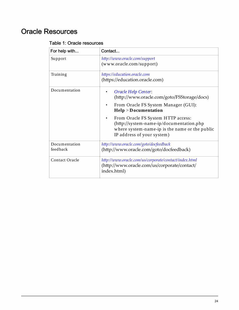
Oracle ResourcesTable 1: Oracle resourcesFor help with... Contact...Support http://www.oracle.com/support
(www.oracle.com/support)
Training https://education.oracle.com(https://education.oracle.com)
Documentation • Oracle Help Center:(http://www.oracle.com/goto/FSStorage/docs)
• From Oracle FS System Manager (GUI):Help > Documentation
• From Oracle FS System HTTP access:(http://system-name-ip/documentation.phpwhere system-name-ip is the name or the publicIP address of your system)
Documentationfeedback
http://www.oracle.com/goto/docfeedback(http://www.oracle.com/goto/docfeedback)
Contact Oracle http://www.oracle.com/us/corporate/contact/index.html(http://www.oracle.com/us/corporate/contact/index.html)
24
CHAPTER 1
Introduction to Oracle FS1-2 System ServiceProcedures
Oracle FS System Service ProceduresController Components
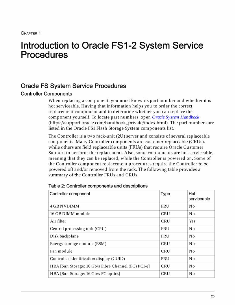
When replacing a component, you must know its part number and whether it ishot serviceable. Having that information helps you to order the correctreplacement component and to determine whether you can replace thecomponent yourself. To locate part numbers, open Oracle System Handbook(https://support.oracle.com/handbook_private/index.html). The part numbers arelisted in the Oracle FS1 Flash Storage System components list.
The Controller is a two rack-unit (2U) server and consists of several replaceablecomponents. Many Controller components are customer replaceable (CRUs),while others are field replaceable units (FRUs) that require Oracle CustomerSupport to perform the replacement. Also, some components are hot-serviceable,meaning that they can be replaced, while the Controller is powered on. Some ofthe Controller component replacement procedures require the Controller to bepowered off and/or removed from the rack. The following table provides asummary of the Controller FRUs and CRUs.
Table 2: Controller components and descriptionsController component Type Hot
serviceable4 GB NVDIMM FRU No
16 GB DIMM module CRU No
Air filter CRU Yes
Central processing unit (CPU) FRU No
Disk backplane FRU No
Energy storage module (ESM) CRU No
Fan module CRU No
Controller identification display (CUID) FRU No
HBA [Sun Storage: 16 Gb/s Fibre Channel (FC) PCI-e] CRU No
HBA [Sun Storage: 16 Gb/s FC optics] CRU No
25
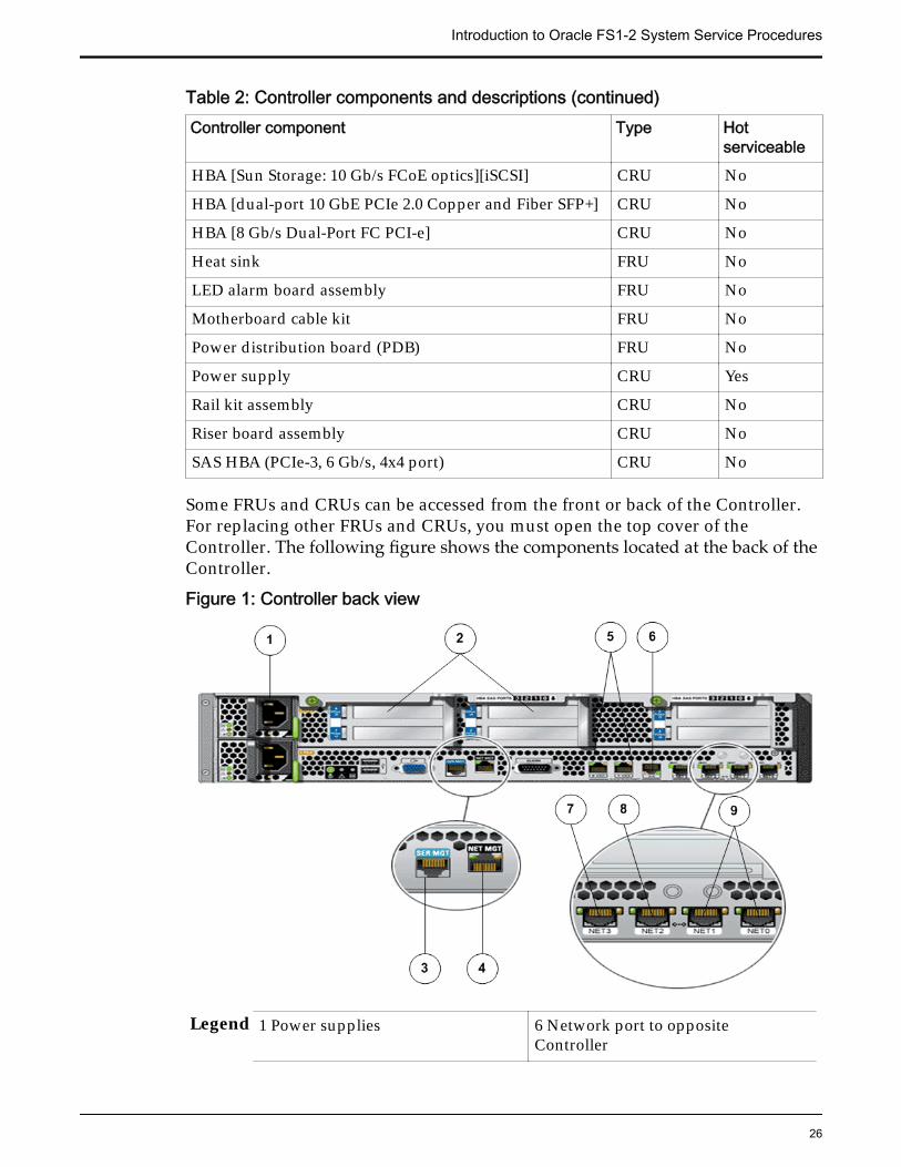
Table 2: Controller components and descriptions (continued)Controller component Type Hot
serviceableHBA [Sun Storage: 10 Gb/s FCoE optics][iSCSI] CRU No
HBA [dual-port 10 GbE PCIe 2.0 Copper and Fiber SFP+] CRU No
HBA [8 Gb/s Dual-Port FC PCI-e] CRU No
Heat sink FRU No
LED alarm board assembly FRU No
Motherboard cable kit FRU No
Power distribution board (PDB) FRU No
Power supply CRU Yes
Rail kit assembly CRU No
Riser board assembly CRU No
SAS HBA (PCIe-3, 6 Gb/s, 4x4 port) CRU No
Some FRUs and CRUs can be accessed from the front or back of the Controller.For replacing other FRUs and CRUs, you must open the top cover of theController. The following figure shows the components located at the back of theController.
Figure 1: Controller back view
Legend 1 Power supplies 6 Network port to oppositeController
Introduction to Oracle FS1-2 System Service Procedures
26
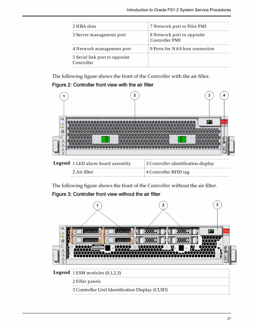
2 HBA slots 7 Network port to Pilot PMI
3 Server management port 8 Network port to oppositeController PMI
4 Network management port 9 Ports for NAS host connection
5 Serial link port to oppositeController
The following figure shows the front of the Controller with the air filter.
Figure 2: Controller front view with the air filter
Legend 1 LED alarm board assembly 3 Controller identification display
2 Air filter 4 Controller RFID tag
The following figure shows the front of the Controller without the air filter.
Figure 3: Controller front view without the air filter
Legend 1 ESM modules (0,1,2,3)
2 Filler panels
3 Controller Unit Identification Display (CUID)
Introduction to Oracle FS1-2 System Service Procedures
27
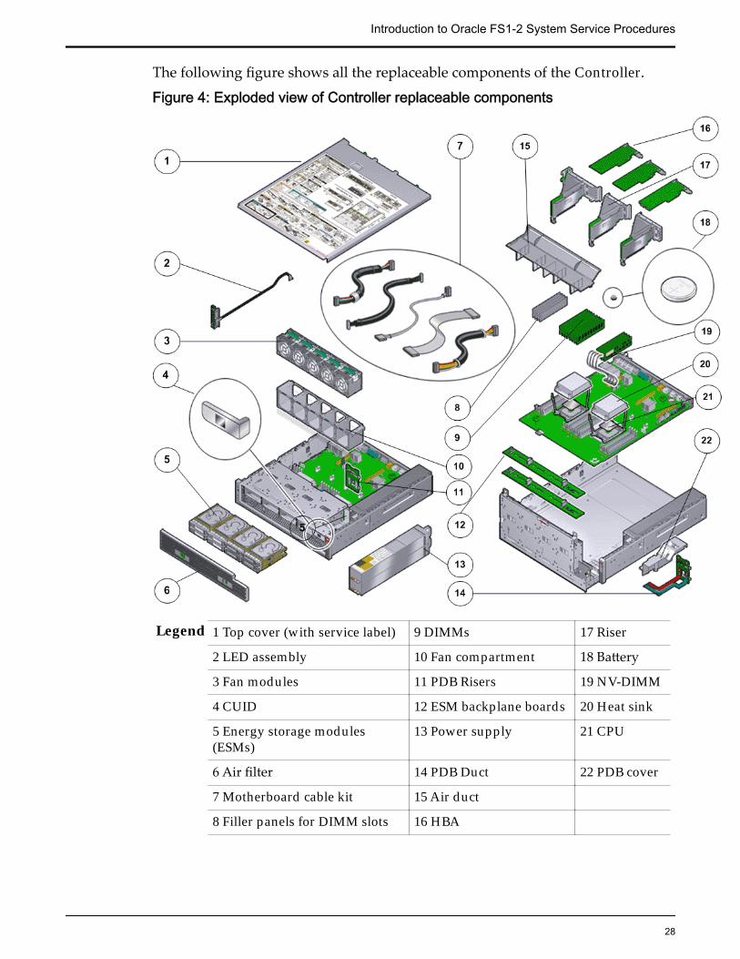
The following figure shows all the replaceable components of the Controller.
Figure 4: Exploded view of Controller replaceable components
Legend 1 Top cover (with service label) 9 DIMMs 17 Riser
2 LED assembly 10 Fan compartment 18 Battery
3 Fan modules 11 PDB Risers 19 NV-DIMM
4 CUID 12 ESM backplane boards 20 Heat sink
5 Energy storage modules(ESMs)
13 Power supply 21 CPU
6 Air filter 14 PDB Duct 22 PDB cover
7 Motherboard cable kit 15 Air duct
8 Filler panels for DIMM slots 16 HBA
Introduction to Oracle FS1-2 System Service Procedures
28
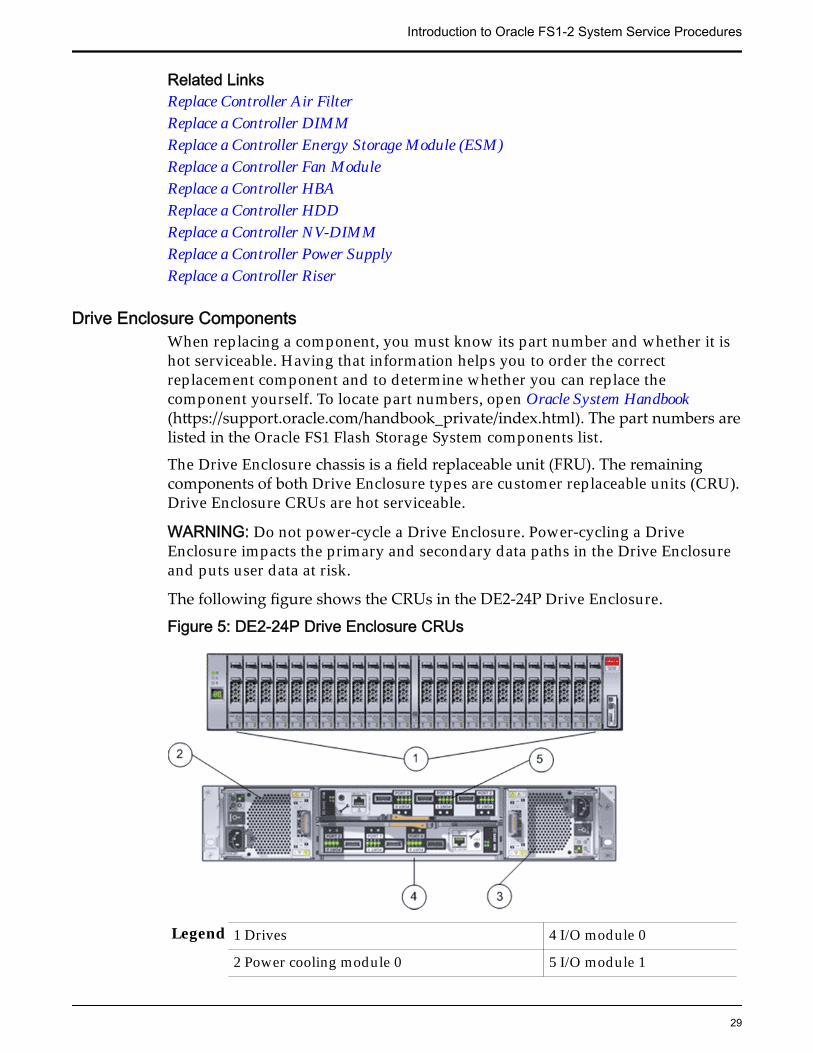
Related LinksReplace Controller Air FilterReplace a Controller DIMMReplace a Controller Energy Storage Module (ESM)Replace a Controller Fan ModuleReplace a Controller HBAReplace a Controller HDDReplace a Controller NV-DIMMReplace a Controller Power SupplyReplace a Controller Riser
Drive Enclosure ComponentsWhen replacing a component, you must know its part number and whether it ishot serviceable. Having that information helps you to order the correctreplacement component and to determine whether you can replace thecomponent yourself. To locate part numbers, open Oracle System Handbook(https://support.oracle.com/handbook_private/index.html). The part numbers arelisted in the Oracle FS1 Flash Storage System components list.
The Drive Enclosure chassis is a field replaceable unit (FRU). The remainingcomponents of both Drive Enclosure types are customer replaceable units (CRU).Drive Enclosure CRUs are hot serviceable.
WARNING: Do not power‑cycle a Drive Enclosure. Power‑cycling a DriveEnclosure impacts the primary and secondary data paths in the Drive Enclosureand puts user data at risk.
The following figure shows the CRUs in the DE2-24P Drive Enclosure.
Figure 5: DE2-24P Drive Enclosure CRUs
Legend 1 Drives 4 I/O module 0
2 Power cooling module 0 5 I/O module 1
Introduction to Oracle FS1-2 System Service Procedures
29
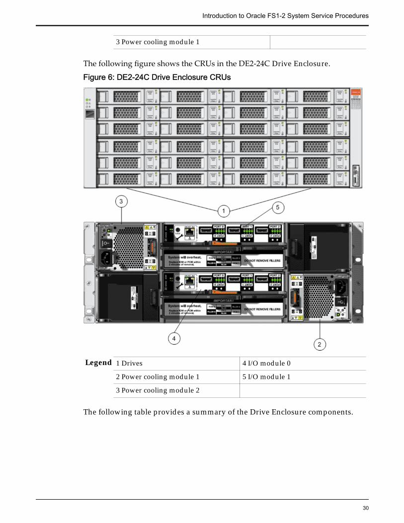
3 Power cooling module 1
The following figure shows the CRUs in the DE2-24C Drive Enclosure.
Figure 6: DE2-24C Drive Enclosure CRUs
Legend 1 Drives 4 I/O module 0
2 Power cooling module 1 5 I/O module 1
3 Power cooling module 2
The following table provides a summary of the Drive Enclosure components.
Introduction to Oracle FS1-2 System Service Procedures
30
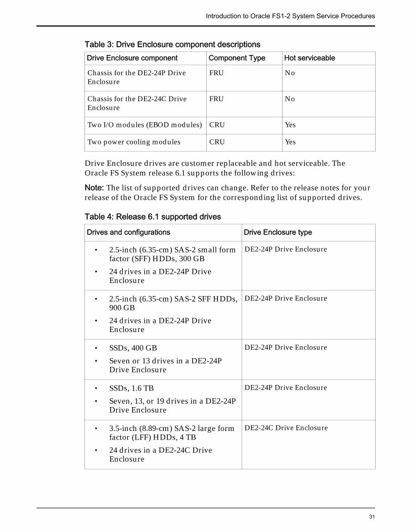
Table 3: Drive Enclosure component descriptionsDrive Enclosure component Component Type Hot serviceable
Chassis for the DE2-24P DriveEnclosure
FRU No
Chassis for the DE2-24C DriveEnclosure
FRU No
Two I/O modules (EBOD modules) CRU Yes
Two power cooling modules CRU Yes
Drive Enclosure drives are customer replaceable and hot serviceable. TheOracle FS System release 6.1 supports the following drives:
Note: The list of supported drives can change. Refer to the release notes for yourrelease of the Oracle FS System for the corresponding list of supported drives.
Table 4: Release 6.1 supported drives
Drives and configurations Drive Enclosure type
• 2.5-inch (6.35-cm) SAS-2 small formfactor (SFF) HDDs, 300 GB
• 24 drives in a DE2-24P DriveEnclosure
DE2-24P Drive Enclosure
• 2.5-inch (6.35-cm) SAS-2 SFF HDDs,900 GB
• 24 drives in a DE2-24P DriveEnclosure
DE2-24P Drive Enclosure
• SSDs, 400 GB• Seven or 13 drives in a DE2-24P
Drive Enclosure
DE2-24P Drive Enclosure
• SSDs, 1.6 TB• Seven, 13, or 19 drives in a DE2-24P
Drive Enclosure
DE2-24P Drive Enclosure
• 3.5-inch (8.89-cm) SAS-2 large formfactor (LFF) HDDs, 4 TB
• 24 drives in a DE2-24C DriveEnclosure
DE2-24C Drive Enclosure
Introduction to Oracle FS1-2 System Service Procedures
31
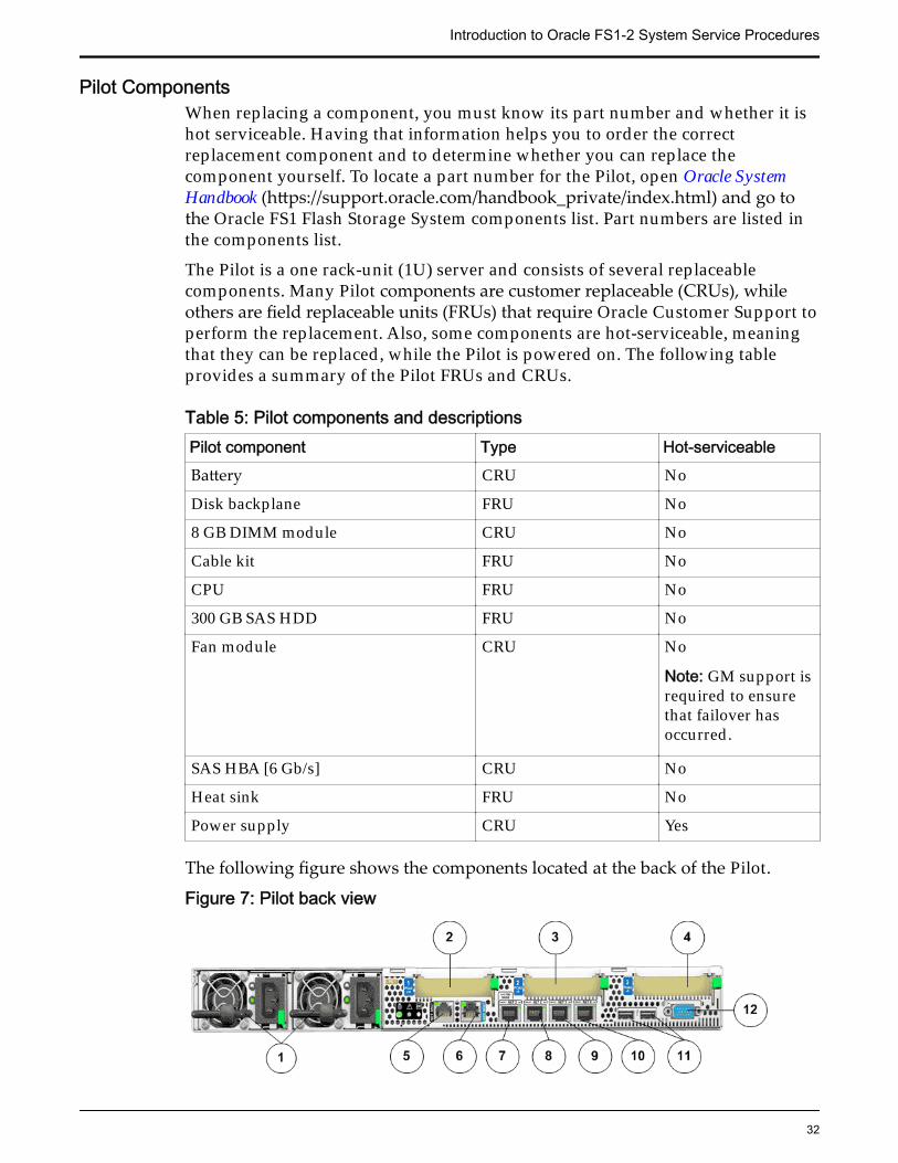
Pilot ComponentsWhen replacing a component, you must know its part number and whether it ishot serviceable. Having that information helps you to order the correctreplacement component and to determine whether you can replace thecomponent yourself. To locate a part number for the Pilot, open Oracle SystemHandbook (https://support.oracle.com/handbook_private/index.html) and go tothe Oracle FS1 Flash Storage System components list. Part numbers are listed inthe components list.
The Pilot is a one rack-unit (1U) server and consists of several replaceablecomponents. Many Pilot components are customer replaceable (CRUs), whileothers are field replaceable units (FRUs) that require Oracle Customer Support toperform the replacement. Also, some components are hot-serviceable, meaningthat they can be replaced, while the Pilot is powered on. The following tableprovides a summary of the Pilot FRUs and CRUs.
Table 5: Pilot components and descriptionsPilot component Type Hot-serviceableBattery CRU No
Disk backplane FRU No
8 GB DIMM module CRU No
Cable kit FRU No
CPU FRU No
300 GB SAS HDD FRU No
Fan module CRU No
Note: GM support isrequired to ensurethat failover hasoccurred.
SAS HBA [6 Gb/s] CRU No
Heat sink FRU No
Power supply CRU Yes
The following figure shows the components located at the back of the Pilot.
Figure 7: Pilot back view
Introduction to Oracle FS1-2 System Service Procedures
32
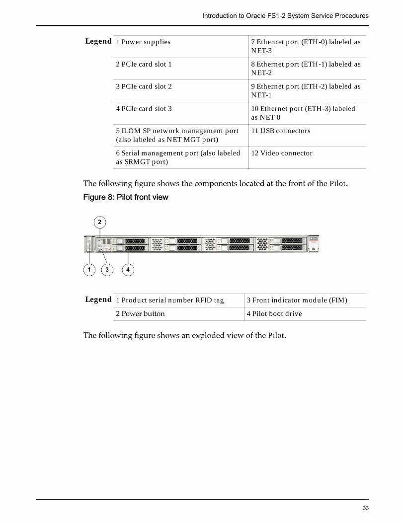
Legend 1 Power supplies 7 Ethernet port (ETH-0) labeled asNET-3
2 PCIe card slot 1 8 Ethernet port (ETH-1) labeled asNET-2
3 PCIe card slot 2 9 Ethernet port (ETH-2) labeled asNET-1
4 PCIe card slot 3 10 Ethernet port (ETH-3) labeledas NET-0
5 ILOM SP network management port(also labeled as NET MGT port)
11 USB connectors
6 Serial management port (also labeledas SRMGT port)
12 Video connector
The following figure shows the components located at the front of the Pilot.
Figure 8: Pilot front view
Legend 1 Product serial number RFID tag 3 Front indicator module (FIM)
2 Power button 4 Pilot boot drive
The following figure shows an exploded view of the Pilot.
Introduction to Oracle FS1-2 System Service Procedures
33
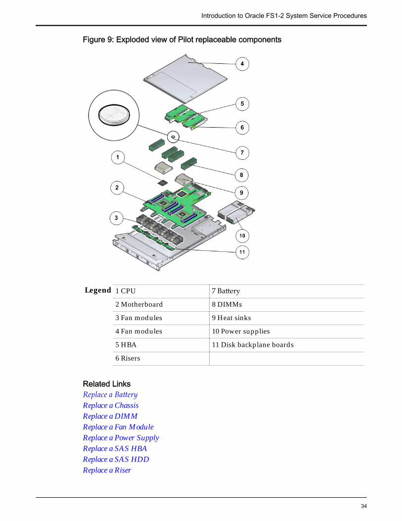
Figure 9: Exploded view of Pilot replaceable components
Legend 1 CPU 7 Battery
2 Motherboard 8 DIMMs
3 Fan modules 9 Heat sinks
4 Fan modules 10 Power supplies
5 HBA 11 Disk backplane boards
6 Risers
Related LinksReplace a BatteryReplace a ChassisReplace a DIMMReplace a Fan ModuleReplace a Power SupplyReplace a SAS HBAReplace a SAS HDDReplace a Riser
Introduction to Oracle FS1-2 System Service Procedures
34
Warnings and CautionsHazard signal words conform to the American National Standards Institute(ANSI) Z535.4-2002 meanings.
CAUTION: Indicates a potentially hazardous situation that, if not avoided, mayresult in minor or moderate injury.
DANGER: Indicates an imminently hazardous situation that, if not avoided, willresult in death or serious injury.
Tip: To indicate best practices for a process.
Important: To emphasize a point, to remind you of something, or to indicatepotential problems in the outcome of the in-process task.
Electrostatic Discharge PrecautionsCAUTION: Before you handle a component, make sure that you have takenelectrostatic discharge (ESD) precautions:
• The minimum requirement is an anti-static wrist strap connected to a hardground. Remove components from their packaging and place them on anESD-qualified table that is equipped with ground points for wrist straps.
• Static charges can build up rapidly on rolling carts. If you transport ahardware component by cart, ground the cart with a drag chain on an ESDfloor. If there is no ESD cart available or ESD floor, ground yourself beforeyou touch a component that has been transported on a cart.
Key Identity Properties (KIP) Automated UpdateOracle ILOM includes a Key Identity Properties (KIP) auto-update feature thatensures product information that is used for service entitlement and warrantycoverage is accurately maintained by the Pilots and Controllers at all times, evenduring hardware replacement service activities.
The KIP includes the component product name, product part number (PPN), andproduct serial number (PSN). The KIP information is stored in the replaceableunit identifiers container of the three replaceable units that are designated as thequorum members for the component.
The Pilot quorum members include:
• Disk backplane (DBP), designated as the primary quorum member
• Motherboard (MB), designated as a backup quorum member
• Power supply–0 (PS-0) designated as a backup quorum member
The Controller quorum members include:
• Disk backplane (DBP), designated as the primary quorum member
• Motherboard (MB), designated as a backup quorum member
• Power Distribution Board (PDB) designated as a backup quorum member
Introduction to Oracle FS1-2 System Service Procedures
35
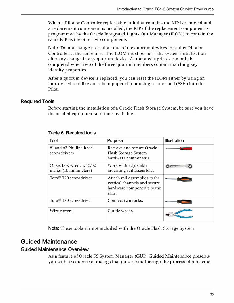
When a Pilot or Controller replaceable unit that contains the KIP is removed anda replacement component is installed, the KIP of the replacement component isprogrammed by the Oracle Integrated Lights Out Manager (ILOM) to contain thesame KIP as the other two components.
Note: Do not change more than one of the quorum devices for either Pilot orController at the same time. The ILOM must perform the system initializationafter any change in any quorum device. Automated updates can only becompleted when two of the three quorum members contain matching keyidentity properties.
After a quorum device is replaced, you can reset the ILOM either by using animprovised tool like an unbent paper clip or using secure shell (SSH) into thePilot.
Required ToolsBefore starting the installation of a Oracle Flash Storage System, be sure you havethe needed equipment and tools available.
Table 6: Required toolsTool Purpose Illustration#1 and #2 Phillips-headscrewdrivers
Remove and secure OracleFlash Storage Systemhardware components.
Offset box wrench, 13/32inches (10 millimeters)
Work with adjustablemounting rail assemblies.
Torx® T20 screwdriver Attach rail assemblies to thevertical channels and securehardware components to therails.
Torx® T30 screwdriver Connect two racks.
Wire cutters Cut tie wraps.
Note: These tools are not included with the Oracle Flash Storage System.
Guided MaintenanceGuided Maintenance Overview
As a feature of Oracle FS System Manager (GUI), Guided Maintenance presentsyou with a sequence of dialogs that guides you through the process of replacing
Introduction to Oracle FS1-2 System Service Procedures
36

field replaceable units (FRUs) and customer replaceable units (CRUs). Promptreplacement of failed FRUs and CRUs helps maintain system reliability.
Guided Maintenance supports the identification and replacement of FRUs andCRUs for Controllers and Drive Enclosures. Guided Maintenance performs thefollowing functions to help you replace FRUs and CRUs:
• Determines the status of the hardware based on events and diagnostics toaccurately reflect the sate of the system.
• Identifies the affected Controller or Drive Enclosure. During the identifyprocess, Guided Maintenance issues a command to light the LEDs on theaffected chassis.
If you are replacing a component on a Drive Enclosure, the following LEDsflash:
Drive Flashes the Locate LED on the Drive Enclosure chassisand the Fault LED on the selected drive.
Power coolingmodule
Flashes the Locate LED on the Drive Enclosure chassisand the Fan Fail LED on the selected power coolingmodule.
I/O module Flashes the Locate LED on the Drive Enclosure chassisand the Fault/Locate LED on the selected I/O module.
If you are replacing a component on the Controller, the following LEDsflash:
Energy StorageModule (ESM)
Flashes the Locate LED on the front of theController chassis, the Status LED on the back ofthe Controller chassis, and the Ready to RemoveLED on the ESM.
All of the remainingControllercomponents
Flashes the Locate LED on the Controller chassisand the Status LED on the back of the Controllerchassis.
During reverse identify, Guided Maintenance issues a command to lightthe LEDs on all of the chassis except for the affected chassis.
• Prepares the Oracle FS System for component replacement. For FRUs andCRUs that require you to bring the chassis offline, Guided Maintenanceissues commands to redirect activity from a failed component to aredundant component and then brings the chassis offline.
• Displays replacement procedures for the failed FRU or CRU. For hot-serviceable FRUs and CRUs, Guided Maintenance presents a sequence ofdialogs with the replacement steps. For FRUs or CRUs that require you tobring the chassis offline, Guided Maintenance provides a link todocumentation containing the replacement steps.
Note: Only administrator accounts set up with support role privileges can accessGuided Maintenance to replace FRUs.
Introduction to Oracle FS1-2 System Service Procedures
37
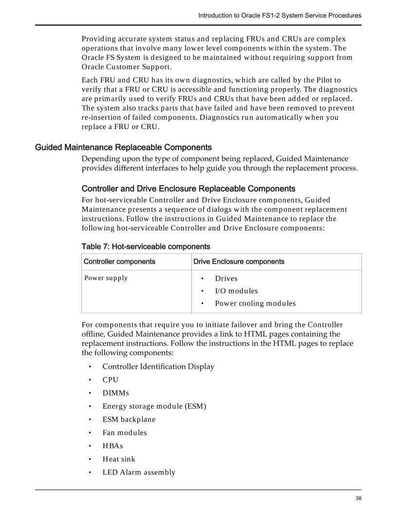
Providing accurate system status and replacing FRUs and CRUs are complexoperations that involve many lower level components within the system. TheOracle FS System is designed to be maintained without requiring support fromOracle Customer Support.
Each FRU and CRU has its own diagnostics, which are called by the Pilot toverify that a FRU or CRU is accessible and functioning properly. The diagnosticsare primarily used to verify FRUs and CRUs that have been added or replaced.The system also tracks parts that have failed and have been removed to preventre-insertion of failed components. Diagnostics run automatically when youreplace a FRU or CRU.
Guided Maintenance Replaceable ComponentsDepending upon the type of component being replaced, Guided Maintenanceprovides different interfaces to help guide you through the replacement process.
Controller and Drive Enclosure Replaceable ComponentsFor hot-serviceable Controller and Drive Enclosure components, GuidedMaintenance presents a sequence of dialogs with the component replacementinstructions. Follow the instructions in Guided Maintenance to replace thefollowing hot-serviceable Controller and Drive Enclosure components:
Table 7: Hot-serviceable components
Controller components Drive Enclosure components
Power supply • Drives• I/O modules• Power cooling modules
For components that require you to initiate failover and bring the Controlleroffline, Guided Maintenance provides a link to HTML pages containing thereplacement instructions. Follow the instructions in the HTML pages to replacethe following components:
• Controller Identification Display
• CPU
• DIMMs
• Energy storage module (ESM)
• ESM backplane
• Fan modules
• HBAs
• Heat sink
• LED Alarm assembly
Introduction to Oracle FS1-2 System Service Procedures
38
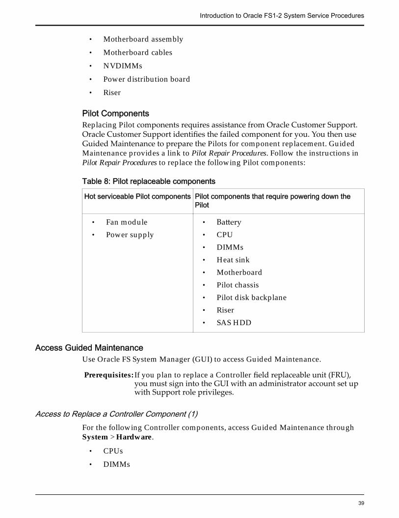
• Motherboard assembly
• Motherboard cables
• NVDIMMs
• Power distribution board
• Riser
Pilot ComponentsReplacing Pilot components requires assistance from Oracle Customer Support.Oracle Customer Support identifies the failed component for you. You then useGuided Maintenance to prepare the Pilots for component replacement. GuidedMaintenance provides a link to Pilot Repair Procedures. Follow the instructions inPilot Repair Procedures to replace the following Pilot components:
Table 8: Pilot replaceable components
Hot serviceable Pilot components Pilot components that require powering down thePilot
• Fan module• Power supply
• Battery• CPU• DIMMs• Heat sink• Motherboard• Pilot chassis• Pilot disk backplane• Riser• SAS HDD
Access Guided MaintenanceUse Oracle FS System Manager (GUI) to access Guided Maintenance.
Prerequisites: If you plan to replace a Controller field replaceable unit (FRU),you must sign into the GUI with an administrator account set upwith Support role privileges.
Access to Replace a Controller Component (1)For the following Controller components, access Guided Maintenance throughSystem > Hardware.
• CPUs
• DIMMs
Introduction to Oracle FS1-2 System Service Procedures
39
• Energy Storage Modules (ESMs)
• Fan modules
• Motherboard
• NVDIMMs
• Power supplies
1 From Oracle FS System Manager (GUI), navigate to System > Hardware.
2 Select Controllers.The GUI displays the Controllers Overview page. The ControllersOverview pages displays the status of the Controller components.
3 Select the Controller containing the component that is to be replaced.
4 Select Actions > View.The View Controller dialog displays the list of replaceable Controllercomponents in the Replaceable Unit list.
5 From the Replaceable Unit list, select the component that you want toreplace and click Replace Component.Guided Maintenance displays the Introduction page and guides youthrough the steps to replace the Controller component.
Access to Replace a Controller Component (2)For the following Controller components, access Guided Maintenance throughSupport > System Trouble.
• Customer identification display
• ESM backplane
• Heat sink
• LED alarm assembly
• Motherboard cables
• Power distribution board
• PCIe Riser
1 From Oracle FS System Manager (GUI), navigate to Support > SystemTrouble.
2 Select the Controller that contains the component that is to be replaced.
3 Select Actions > Replace Component.Guided Maintenance displays the list of replaceable components for theController.
Note: Field replaceable units (FRUs) can only be replaced by fieldtechnicians with support role privileges.
4 Select a component from the list.
Introduction to Oracle FS1-2 System Service Procedures
40
Guided Maintenance displays the Introduction page and guides youthrough the steps to replace the Controller component.
Access to Replace a Drive Enclosure Component1 From Oracle FS System Manager (GUI), navigate to System > Hardware.
2 Select Drive Enclosures.The GUI displays the Drive Enclosures Overview page. The DriveEnclosures Overview page displays the status of the Drive Enclosurecomponents.
3 Select the Drive Enclosure containing the component that you want toreplace.
4 Select Actions > View.The View Drive Enclosure dialog displays the list of replaceable DriveEnclosure components in the Replaceable Unit list.
5 From the Replaceable Unit list, select the component that you want toreplace and click Replace Component.Guided Maintenance displays the Introduction page, and guides youthrough the steps to replace the Drive Enclosure component.
Access to Replace a Pilot Component1 From Oracle FS System Manager (GUI), navigate to System > Hardware.
2 Select Pilots.The GUI displays the Pilots Overview page.
3 Select a Pilot.
4 Select Actions > Repair Pilot.Guided Maintenance displays the Pilot Repair page and guides youthrough the steps to replace a Pilot component.
Introduction to Oracle FS1-2 System Service Procedures
41
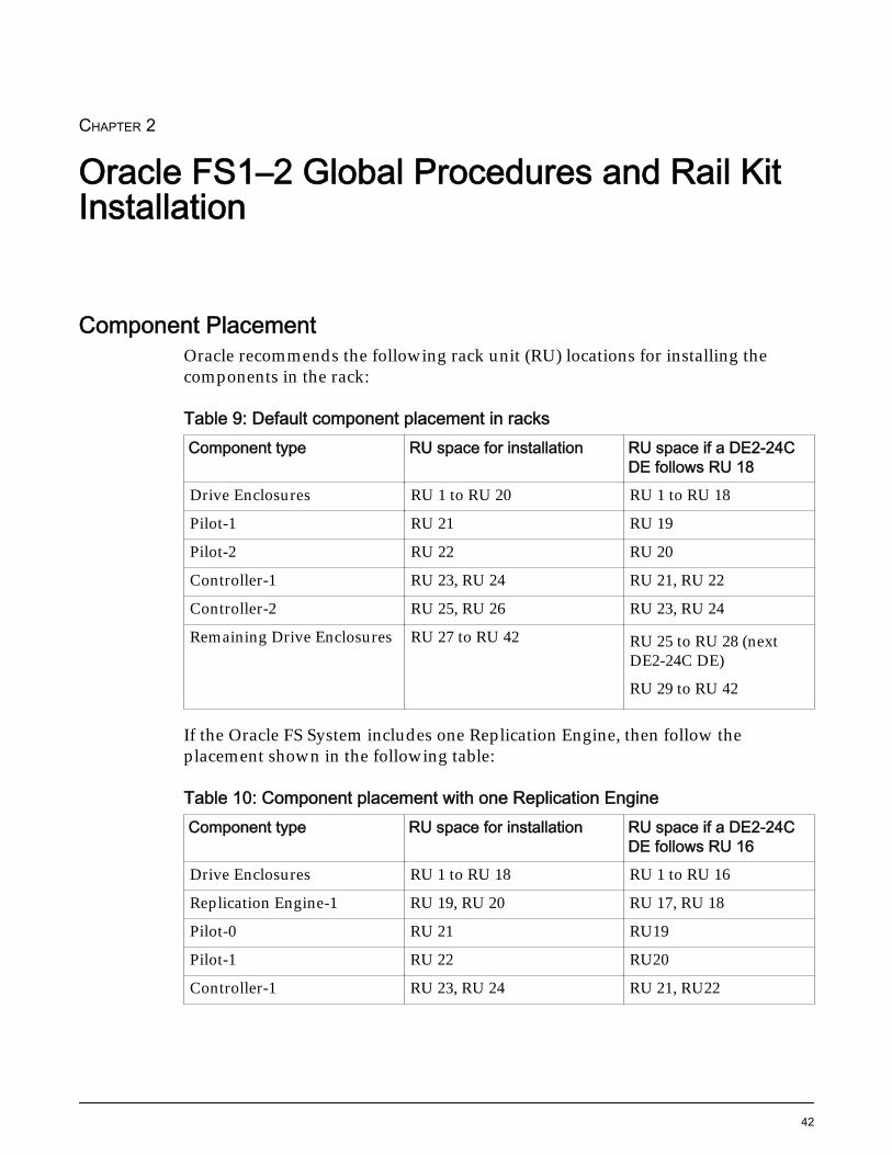
CHAPTER 2
Oracle FS1–2 Global Procedures and Rail KitInstallation
Component PlacementOracle recommends the following rack unit (RU) locations for installing thecomponents in the rack:
Table 9: Default component placement in racksComponent type RU space for installation RU space if a DE2-24C
DE follows RU 18Drive Enclosures RU 1 to RU 20 RU 1 to RU 18
Pilot-1 RU 21 RU 19
Pilot-2 RU 22 RU 20
Controller-1 RU 23, RU 24 RU 21, RU 22
Controller-2 RU 25, RU 26 RU 23, RU 24
Remaining Drive Enclosures RU 27 to RU 42 RU 25 to RU 28 (nextDE2-24C DE)
RU 29 to RU 42
If the Oracle FS System includes one Replication Engine, then follow theplacement shown in the following table:
Table 10: Component placement with one Replication EngineComponent type RU space for installation RU space if a DE2-24C
DE follows RU 16Drive Enclosures RU 1 to RU 18 RU 1 to RU 16
Replication Engine-1 RU 19, RU 20 RU 17, RU 18
Pilot-0 RU 21 RU19
Pilot-1 RU 22 RU20
Controller-1 RU 23, RU 24 RU 21, RU22
42
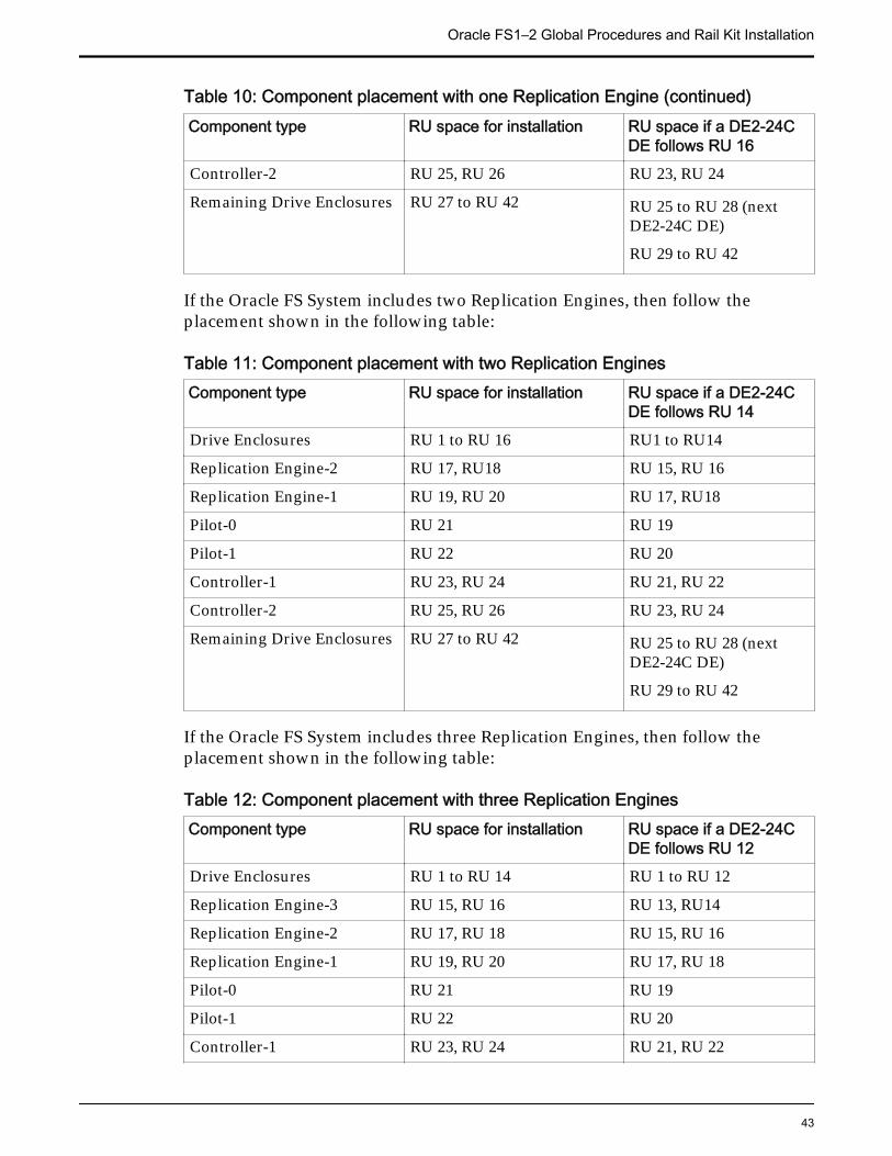
Table 10: Component placement with one Replication Engine (continued)Component type RU space for installation RU space if a DE2-24C
DE follows RU 16Controller-2 RU 25, RU 26 RU 23, RU 24
Remaining Drive Enclosures RU 27 to RU 42 RU 25 to RU 28 (nextDE2-24C DE)
RU 29 to RU 42
If the Oracle FS System includes two Replication Engines, then follow theplacement shown in the following table:
Table 11: Component placement with two Replication EnginesComponent type RU space for installation RU space if a DE2-24C
DE follows RU 14Drive Enclosures RU 1 to RU 16 RU1 to RU14
Replication Engine-2 RU 17, RU18 RU 15, RU 16
Replication Engine-1 RU 19, RU 20 RU 17, RU18
Pilot-0 RU 21 RU 19
Pilot-1 RU 22 RU 20
Controller-1 RU 23, RU 24 RU 21, RU 22
Controller-2 RU 25, RU 26 RU 23, RU 24
Remaining Drive Enclosures RU 27 to RU 42 RU 25 to RU 28 (nextDE2-24C DE)
RU 29 to RU 42
If the Oracle FS System includes three Replication Engines, then follow theplacement shown in the following table:
Table 12: Component placement with three Replication EnginesComponent type RU space for installation RU space if a DE2-24C
DE follows RU 12Drive Enclosures RU 1 to RU 14 RU 1 to RU 12
Replication Engine-3 RU 15, RU 16 RU 13, RU14
Replication Engine-2 RU 17, RU 18 RU 15, RU 16
Replication Engine-1 RU 19, RU 20 RU 17, RU 18
Pilot-0 RU 21 RU 19
Pilot-1 RU 22 RU 20
Controller-1 RU 23, RU 24 RU 21, RU 22
Oracle FS1–2 Global Procedures and Rail Kit Installation
43
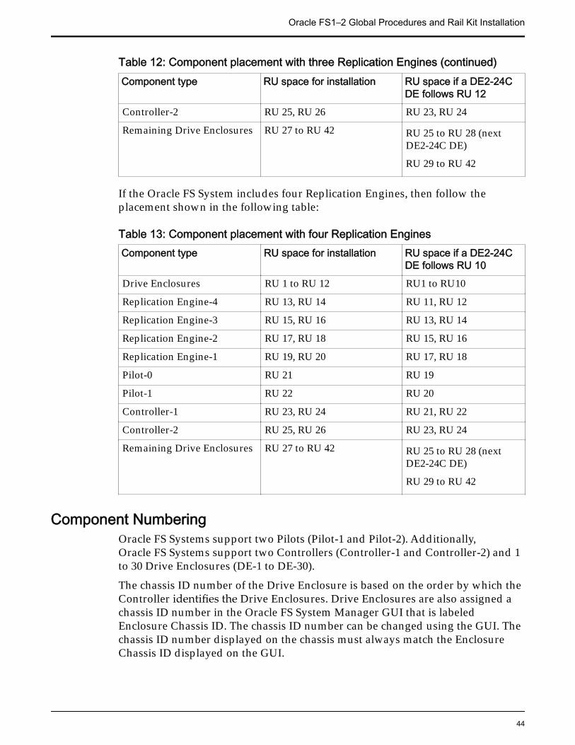
Table 12: Component placement with three Replication Engines (continued)Component type RU space for installation RU space if a DE2-24C
DE follows RU 12Controller-2 RU 25, RU 26 RU 23, RU 24
Remaining Drive Enclosures RU 27 to RU 42 RU 25 to RU 28 (nextDE2-24C DE)
RU 29 to RU 42
If the Oracle FS System includes four Replication Engines, then follow theplacement shown in the following table:
Table 13: Component placement with four Replication EnginesComponent type RU space for installation RU space if a DE2-24C
DE follows RU 10Drive Enclosures RU 1 to RU 12 RU1 to RU10
Replication Engine-4 RU 13, RU 14 RU 11, RU 12
Replication Engine-3 RU 15, RU 16 RU 13, RU 14
Replication Engine-2 RU 17, RU 18 RU 15, RU 16
Replication Engine-1 RU 19, RU 20 RU 17, RU 18
Pilot-0 RU 21 RU 19
Pilot-1 RU 22 RU 20
Controller-1 RU 23, RU 24 RU 21, RU 22
Controller-2 RU 25, RU 26 RU 23, RU 24
Remaining Drive Enclosures RU 27 to RU 42 RU 25 to RU 28 (nextDE2-24C DE)
RU 29 to RU 42
Component NumberingOracle FS Systems support two Pilots (Pilot-1 and Pilot-2). Additionally,Oracle FS Systems support two Controllers (Controller-1 and Controller-2) and 1to 30 Drive Enclosures (DE-1 to DE-30).
The chassis ID number of the Drive Enclosure is based on the order by which theController identifies the Drive Enclosures. Drive Enclosures are also assigned achassis ID number in the Oracle FS System Manager GUI that is labeledEnclosure Chassis ID. The chassis ID number can be changed using the GUI. Thechassis ID number displayed on the chassis must always match the EnclosureChassis ID displayed on the GUI.
Oracle FS1–2 Global Procedures and Rail Kit Installation
44
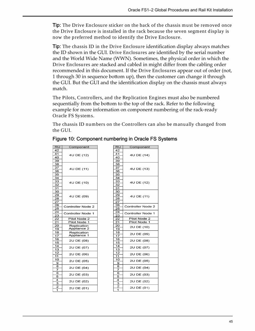
Tip: The Drive Enclosure sticker on the back of the chassis must be removed oncethe Drive Enclosure is installed in the rack because the seven segment display isnow the preferred method to identify the Drive Enclosure.
Tip: The chassis ID in the Drive Enclosure identification display always matchesthe ID shown in the GUI. Drive Enclosures are identified by the serial numberand the World Wide Name (WWN). Sometimes, the physical order in which theDrive Enclosures are stacked and cabled in might differ from the cabling orderrecommended in this document. If the Drive Enclosures appear out of order (not,1 through 30 in sequence bottom up), then the customer can change it throughthe GUI. But the GUI and the identification display on the chassis must alwaysmatch.
The Pilots, Controllers, and the Replication Engines must also be numberedsequentially from the bottom to the top of the rack. Refer to the followingexample for more information on component numbering of the rack-readyOracle FS Systems.
The chassis ID numbers on the Controllers can also be manually changed fromthe GUI.
Figure 10: Component numbering in Oracle FS Systems
Oracle FS1–2 Global Procedures and Rail Kit Installation
45

Note: The above example shows eight DE2–24P Drive Enclosures (2 RU), fourDE2–24C Drive Enclosures (4 RU), and two Replication Engines.
Oracle FS System Rack Hardware SpecificationsAn Oracle FS System can contain a combination of:
• Two Pilot nodes; each node is a 1U Oracle server.
• Two Controllers
• One to 30 Drive Enclosures.
• Two power distribution units (PDUs) built into the rack.
• Replication Engines (optional)
Note: Two racks are required to install 30 Drive Enclosures
Customer supplied racks into which you install the Oracle FS1 Flash StorageSystem components must meet the requirements listed in the following table:
Table 14: Rack specifications for an Oracle FS System
Item Requirement
Structure Four-post rack (mounting at both front andrear).
Supported rack types:
• square hole (9.5 mm)• round hole (M6 or 1/4-20 threaded
only)
Note: Two-post racks are not compatible.
Rack horizontal opening and unitvertical pitch
Conforms to ANSI/EIA 310-D-1992 or IEC60927 standards.
Distance between front and rearmounting planes
• Minimum 24 in (610 mm)• Maximum 36 in (915 mm)
Clearance depth in front of frontmounting plane
Minimum distance to rear cabinet door:
• 35.43 in (900 mm) with the CMA• 31.49 in (800 mm) without the
CMA
Note: CMAs are required for Pilots,Controllers, and Replication Engines.
Oracle FS1–2 Global Procedures and Rail Kit Installation
46
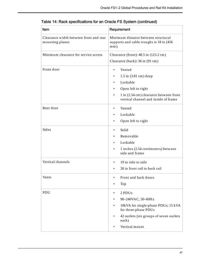
Table 14: Rack specifications for an Oracle FS System (continued)
Item Requirement
Clearance width between front and rearmounting planes
Minimum distance between structuralsupports and cable troughs is 18 in (456mm).
Minimum clearance for service access Clearance (front): 48.5 in (123.2 cm)
Clearance (back): 36 in (91 cm)
Front door • Vented
• 1.5 in (3.81 cm) deep
• Lockable
• Open left to right
• 1 in (2.54 cm) clearance between frontvertical channel and inside of frame
Rear door • Vented
• Lockable
• Open left to right
Sides • Solid
• Removable
• Lockable
• 1 inches (2.54 centimeters) betweenside and frame
Vertical channels • 19 in side to side
• 26 in front rail to back rail
Vents • Front and back doors
• Top
PDU • 2 PDUs
• 90–240VAC, 50–60Hz
• 10kVA for single-phase PDUs; 15 kVAfor three-phase PDUs
• 42 outlets (six groups of seven outletseach)
• Vertical mount
Oracle FS1–2 Global Procedures and Rail Kit Installation
47
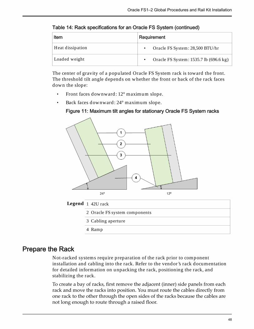
Table 14: Rack specifications for an Oracle FS System (continued)
Item Requirement
Heat dissipation • Oracle FS System: 28,500 BTU/hr
Loaded weight • Oracle FS System: 1535.7 lb (696.6 kg)
The center of gravity of a populated Oracle FS System rack is toward the front.The threshold tilt angle depends on whether the front or back of the rack facesdown the slope:
• Front faces downward: 12° maximum slope.
• Back faces downward: 24° maximum slope.
Figure 11: Maximum tilt angles for stationary Oracle FS System racks
Legend 1 42U rack
2 Oracle FS system components
3 Cabling aperture
4 Ramp
Prepare the RackNot-racked systems require preparation of the rack prior to componentinstallation and cabling into the rack. Refer to the vendor’s rack documentationfor detailed information on unpacking the rack, positioning the rack, andstabilizing the rack.
To create a bay of racks, first remove the adjacent (inner) side panels from eachrack and move the racks into position. You must route the cables directly fromone rack to the other through the open sides of the racks because the cables arenot long enough to route through a raised floor.
Oracle FS1–2 Global Procedures and Rail Kit Installation
48
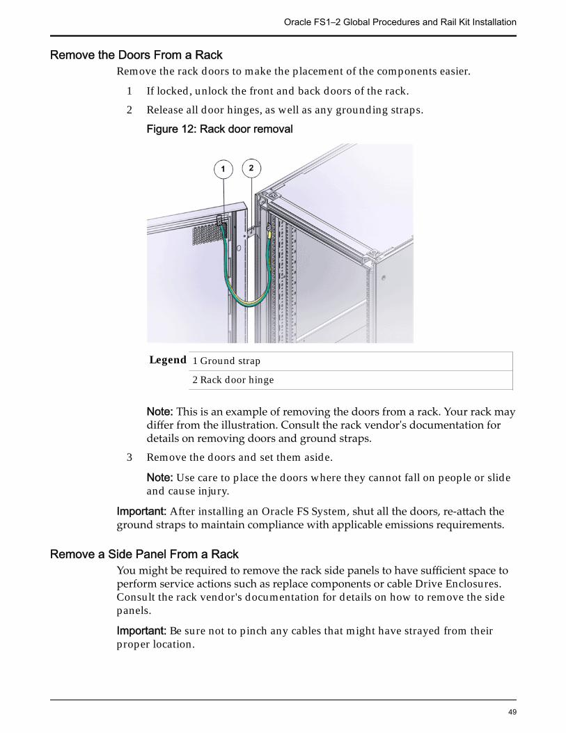
Remove the Doors From a RackRemove the rack doors to make the placement of the components easier.
1 If locked, unlock the front and back doors of the rack.
2 Release all door hinges, as well as any grounding straps.
Figure 12: Rack door removal
Legend 1 Ground strap
2 Rack door hinge
Note: This is an example of removing the doors from a rack. Your rack maydiffer from the illustration. Consult the rack vendor's documentation fordetails on removing doors and ground straps.
3 Remove the doors and set them aside.
Note: Use care to place the doors where they cannot fall on people or slideand cause injury.
Important: After installing an Oracle FS System, shut all the doors, re-attach theground straps to maintain compliance with applicable emissions requirements.
Remove a Side Panel From a RackYou might be required to remove the rack side panels to have sufficient space toperform service actions such as replace components or cable Drive Enclosures.Consult the rack vendor's documentation for details on how to remove the sidepanels.
Important: Be sure not to pinch any cables that might have strayed from theirproper location.
Oracle FS1–2 Global Procedures and Rail Kit Installation
49
Rack Installation Safety PrecautionsFollow these safety precautions when installing the components in the rack.
CAUTION: If non-Oracle FS System equipment must be installed in the rack,additional care must be taken to ensure that this equipment does not causeoverheating of the Oracle FS System components or block air flow. All Oracle FSSystem components meet these requirements, but ONLY if the installation andrack position guidelines are carefully followed.
CAUTION: Always load components into a rack from the bottom to the top sothat the rack does not become top-heavy and tip over.
CAUTION: Avoid elevated operating ambient temperature. If the component isinstalled in a closed or multi-unit rack assembly, the operating ambienttemperature of the rack environment might be greater than room ambienttemperature. Therefore, make sure that the environment is compatible with themaximum ambient temperature (TMA) specified for the component.
CAUTION: Make sure that there is sufficient amount of airflow required for safeoperation of each component.
CAUTION: Mounting of a component in the rack should be such that ahazardous condition is not created due to uneven mechanical loading.
CAUTION: Consideration should be given to the connection of a component tothe supply circuit and the effect that overloading of the circuits might have onover-current protection and supply wiring. Appropriate consideration ofcomponent nameplate power ratings should be used when addressing thisconcern.
CAUTION: Reliable grounding of rack-mounted equipment should bemaintained. Particular attention should be given to supply connections otherthan direct connections to the branch circuit (for example, use of power strips).
CAUTION: Do not use slide-rail mounted equipment as a shelf.
System-Wide ProceduresData Backups
Regular backups are prudent IT practice. When you service hardwarecomponents that directly affect user data paths, we highly recommend that youfirst back up all user data to external media.
Important: Extraordinary system hardware changes (such as replacing aController) and software configuration changes (such as resetting the system to afactory-fresh state) and all other modifications not specifically mentioned in thisdocument should only be attempted after consultation with Oracle CustomerSupport. A backup of data should always be done prior to all but routinemaintenance actions.
Full system backups to external media must be performed when you want toperform any of the following actions:
Oracle FS1–2 Global Procedures and Rail Kit Installation
50
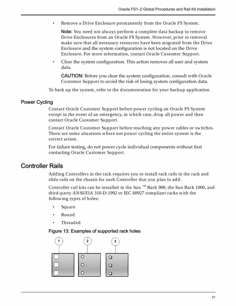
• Remove a Drive Enclosure permanently from the Oracle FS System.
Note: You need not always perform a complete data backup to removeDrive Enclosures from an Oracle FS System. However, prior to removalmake sure that all necessary resources have been migrated from the DriveEnclosure and the system configuration is not located on the DriveEnclosure. For more information, contact Oracle Customer Support.
• Clear the system configuration. This action removes all user and systemdata.
CAUTION: Before you clear the system configuration, consult with OracleCustomer Support to avoid the risk of losing system configuration data.
To back up the system, refer to the documentation for your backup application.
Power CyclingContact Oracle Customer Support before power cycling an Oracle FS Systemexcept in the event of an emergency, in which case, drop all power and thencontact Oracle Customer Support.
Contact Oracle Customer Support before touching any power cables or switches.There are some situations where not power cycling the entire system is thecorrect action.
For failure testing, do not power cycle individual components without firstcontacting Oracle Customer Support.
Controller RailsAdding Controllers in the rack requires you to install rack rails in the rack andslide rails on the chassis for each Controller that you plan to add.
Controller rail kits can be installed in the Sun ™ Rack 900, the Sun Rack 1000, andthird-party ANSI/EIA 310-D-1992 or IEC 60927 compliant racks with thefollowing types of holes:
• Square
• Round
• Threaded
Figure 13: Examples of supported rack holes
Oracle FS1–2 Global Procedures and Rail Kit Installation
51
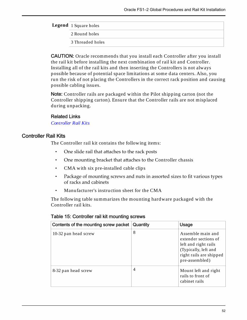
Legend 1 Square holes
2 Round holes
3 Threaded holes
CAUTION: Oracle recommends that you install each Controller after you installthe rail kit before installing the next combination of rail kit and Controller.Installing all of the rail kits and then inserting the Controllers is not alwayspossible because of potential space limitations at some data centers. Also, yourun the risk of not placing the Controllers in the correct rack position and causingpossible cabling issues.
Note: Controller rails are packaged within the Pilot shipping carton (not theController shipping carton). Ensure that the Controller rails are not misplacedduring unpacking.
Related LinksController Rail Kits
Controller Rail KitsThe Controller rail kit contains the following items:
• One slide rail that attaches to the rack posts
• One mounting bracket that attaches to the Controller chassis
• CMA with six pre-installed cable clips
• Package of mounting screws and nuts in assorted sizes to fit various typesof racks and cabinets
• Manufacturer's instruction sheet for the CMA
The following table summarizes the mounting hardware packaged with theController rail kits.
Table 15: Controller rail kit mounting screwsContents of the mounting screw packet Quantity Usage
10-32 pan head screw 8 Assemble main andextender sections ofleft and right rails(Typically, left andright rails are shippedpre-assembled)
8-32 pan head screw 4 Mount left and rightrails to front ofcabinet rails
Oracle FS1–2 Global Procedures and Rail Kit Installation
52
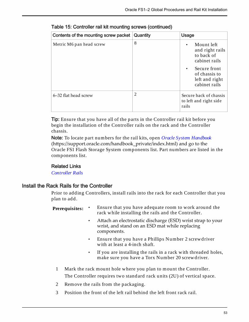
Table 15: Controller rail kit mounting screws (continued)Contents of the mounting screw packet Quantity Usage
Metric M6 pan head screw 8 • Mount leftand right railsto back ofcabinet rails
• Secure frontof chassis toleft and rightcabinet rails
6–32 flat head screw 2 Secure back of chassisto left and right siderails
Tip: Ensure that you have all of the parts in the Controller rail kit before youbegin the installation of the Controller rails on the rack and the Controllerchassis.Note: To locate part numbers for the rail kits, open Oracle System Handbook(https://support.oracle.com/handbook_private/index.html) and go to theOracle FS1 Flash Storage System components list. Part numbers are listed in thecomponents list.
Related LinksController Rails
Install the Rack Rails for the ControllerPrior to adding Controllers, install rails into the rack for each Controller that youplan to add.
Prerequisites: • Ensure that you have adequate room to work around therack while installing the rails and the Controller.
• Attach an electrostatic discharge (ESD) wrist strap to yourwrist, and stand on an ESD mat while replacingcomponents.
• Ensure that you have a Phillips Number 2 screwdriverwith at least a 4-inch shaft.
• If you are installing the rails in a rack with threaded holes,make sure you have a Torx Number 20 screwdriver.
1 Mark the rack mount hole where you plan to mount the Controller.The Controller requires two standard rack units (2U) of vertical space.
2 Remove the rails from the packaging.
3 Position the front of the left rail behind the left front rack rail.
Oracle FS1–2 Global Procedures and Rail Kit Installation
53
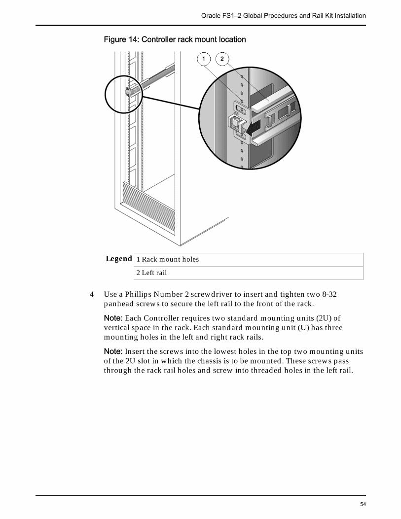
Figure 14: Controller rack mount location
Legend 1 Rack mount holes
2 Left rail
4 Use a Phillips Number 2 screwdriver to insert and tighten two 8-32panhead screws to secure the left rail to the front of the rack.
Note: Each Controller requires two standard mounting units (2U) ofvertical space in the rack. Each standard mounting unit (U) has threemounting holes in the left and right rack rails.
Note: Insert the screws into the lowest holes in the top two mounting unitsof the 2U slot in which the chassis is to be mounted. These screws passthrough the rack rail holes and screw into threaded holes in the left rail.
Oracle FS1–2 Global Procedures and Rail Kit Installation
54
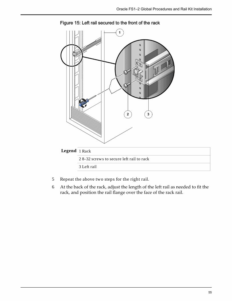
Figure 15: Left rail secured to the front of the rack
Legend 1 Rack
2 8–32 screws to secure left rail to rack
3 Left rail
5 Repeat the above two steps for the right rail.
6 At the back of the rack, adjust the length of the left rail as needed to fit therack, and position the rail flange over the face of the rack rail.
Oracle FS1–2 Global Procedures and Rail Kit Installation
55
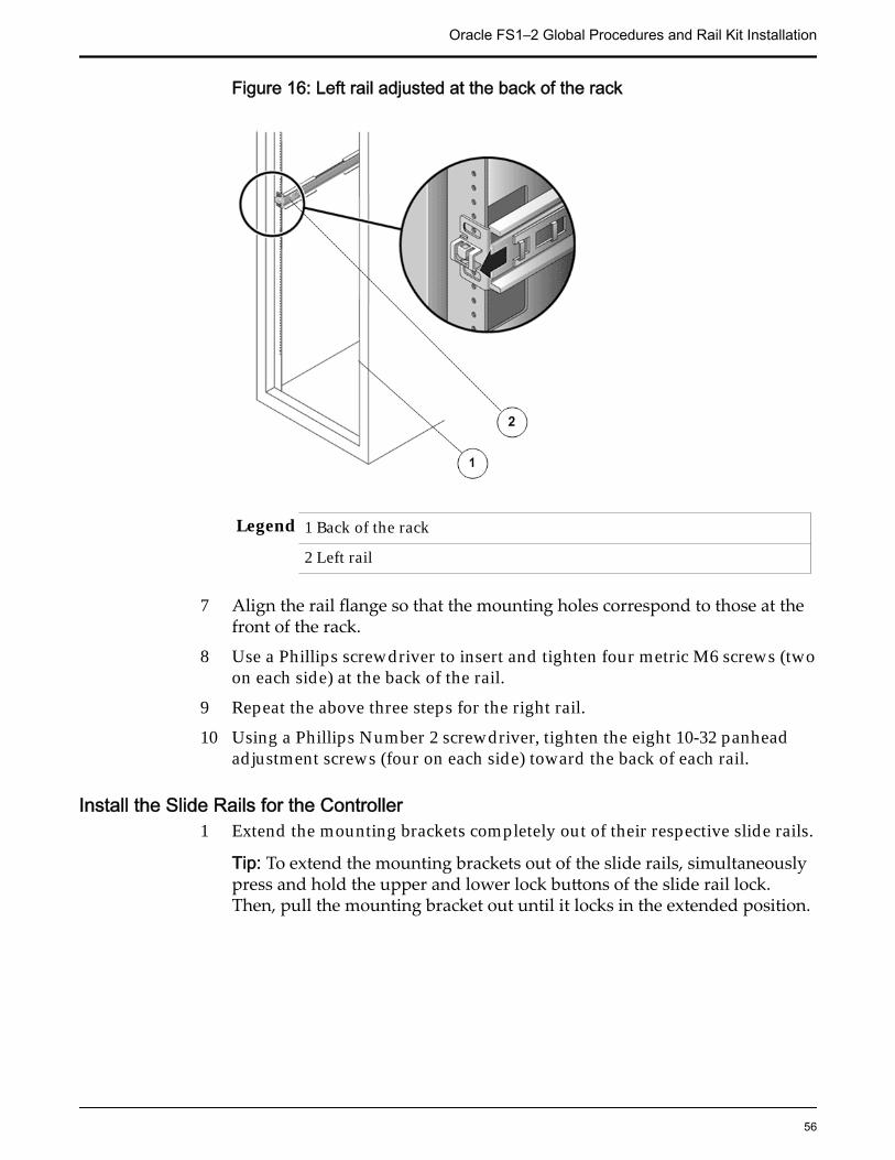
Figure 16: Left rail adjusted at the back of the rack
Legend 1 Back of the rack
2 Left rail
7 Align the rail flange so that the mounting holes correspond to those at thefront of the rack.
8 Use a Phillips screwdriver to insert and tighten four metric M6 screws (twoon each side) at the back of the rail.
9 Repeat the above three steps for the right rail.
10 Using a Phillips Number 2 screwdriver, tighten the eight 10-32 panheadadjustment screws (four on each side) toward the back of each rail.
Install the Slide Rails for the Controller1 Extend the mounting brackets completely out of their respective slide rails.
Tip: To extend the mounting brackets out of the slide rails, simultaneouslypress and hold the upper and lower lock buttons of the slide rail lock.Then, pull the mounting bracket out until it locks in the extended position.
Oracle FS1–2 Global Procedures and Rail Kit Installation
56
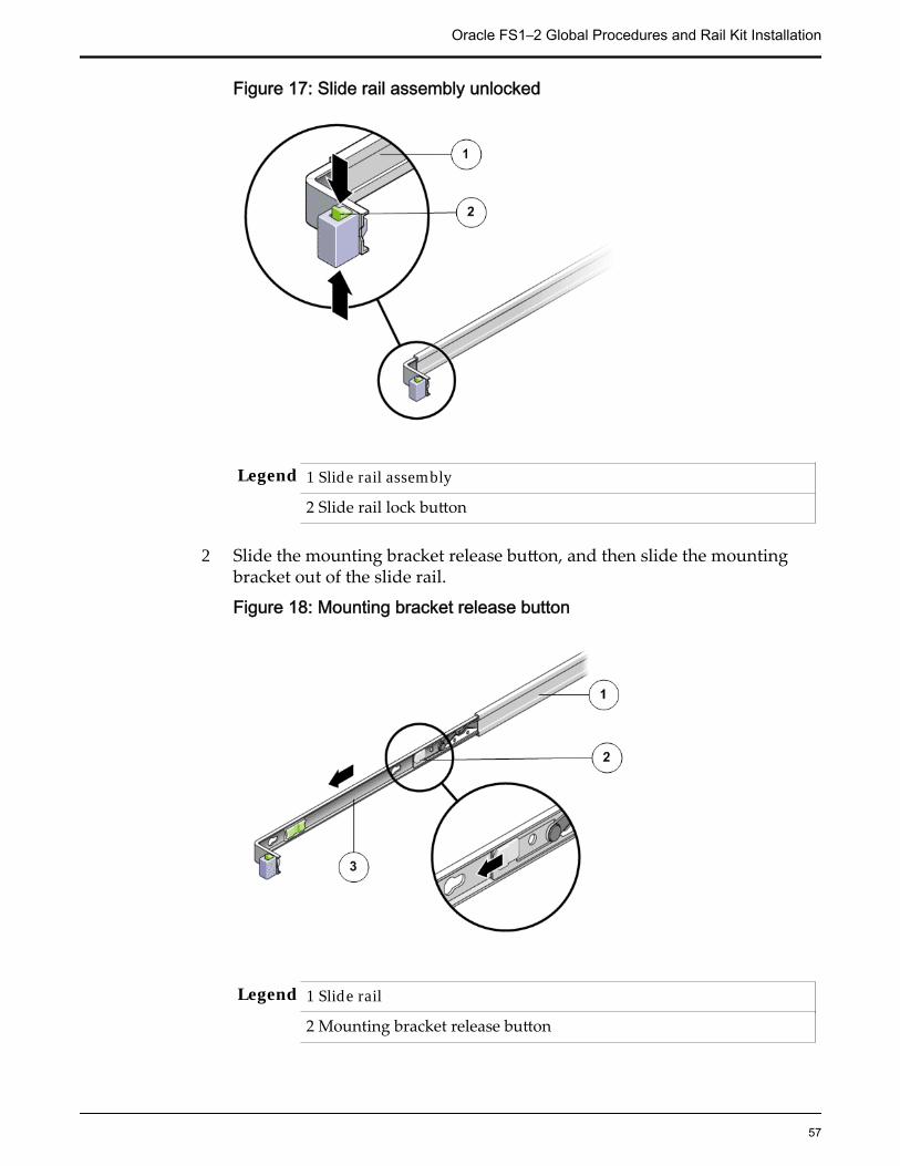
Figure 17: Slide rail assembly unlocked
Legend 1 Slide rail assembly
2 Slide rail lock button
2 Slide the mounting bracket release button, and then slide the mountingbracket out of the slide rail.
Figure 18: Mounting bracket release button
Legend 1 Slide rail
2 Mounting bracket release button
Oracle FS1–2 Global Procedures and Rail Kit Installation
57
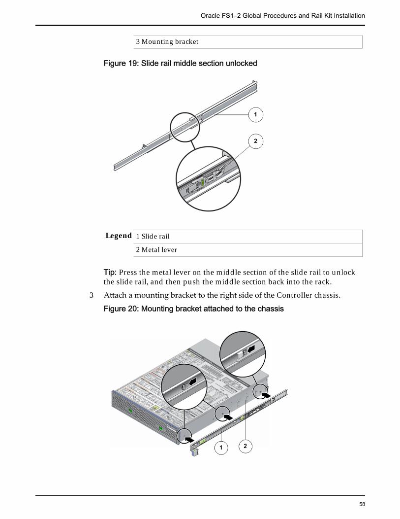
3 Mounting bracket
Figure 19: Slide rail middle section unlocked
Legend 1 Slide rail
2 Metal lever
Tip: Press the metal lever on the middle section of the slide rail to unlockthe slide rail, and then push the middle section back into the rack.
3 Attach a mounting bracket to the right side of the Controller chassis.
Figure 20: Mounting bracket attached to the chassis
Oracle FS1–2 Global Procedures and Rail Kit Installation
58
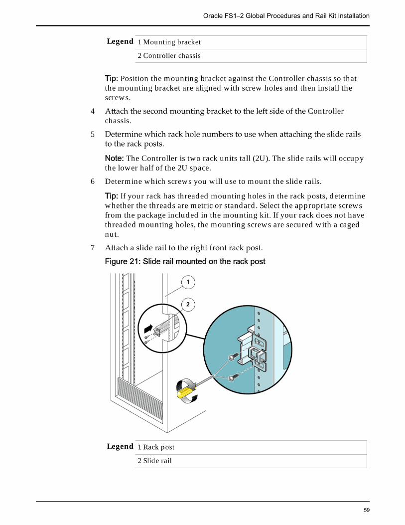
Legend 1 Mounting bracket
2 Controller chassis
Tip: Position the mounting bracket against the Controller chassis so thatthe mounting bracket are aligned with screw holes and then install thescrews.
4 Attach the second mounting bracket to the left side of the Controllerchassis.
5 Determine which rack hole numbers to use when attaching the slide railsto the rack posts.
Note: The Controller is two rack units tall (2U). The slide rails will occupythe lower half of the 2U space.
6 Determine which screws you will use to mount the slide rails.
Tip: If your rack has threaded mounting holes in the rack posts, determinewhether the threads are metric or standard. Select the appropriate screwsfrom the package included in the mounting kit. If your rack does not havethreaded mounting holes, the mounting screws are secured with a cagednut.
7 Attach a slide rail to the right front rack post.
Figure 21: Slide rail mounted on the rack post
Legend 1 Rack post
2 Slide rail
Oracle FS1–2 Global Procedures and Rail Kit Installation
59
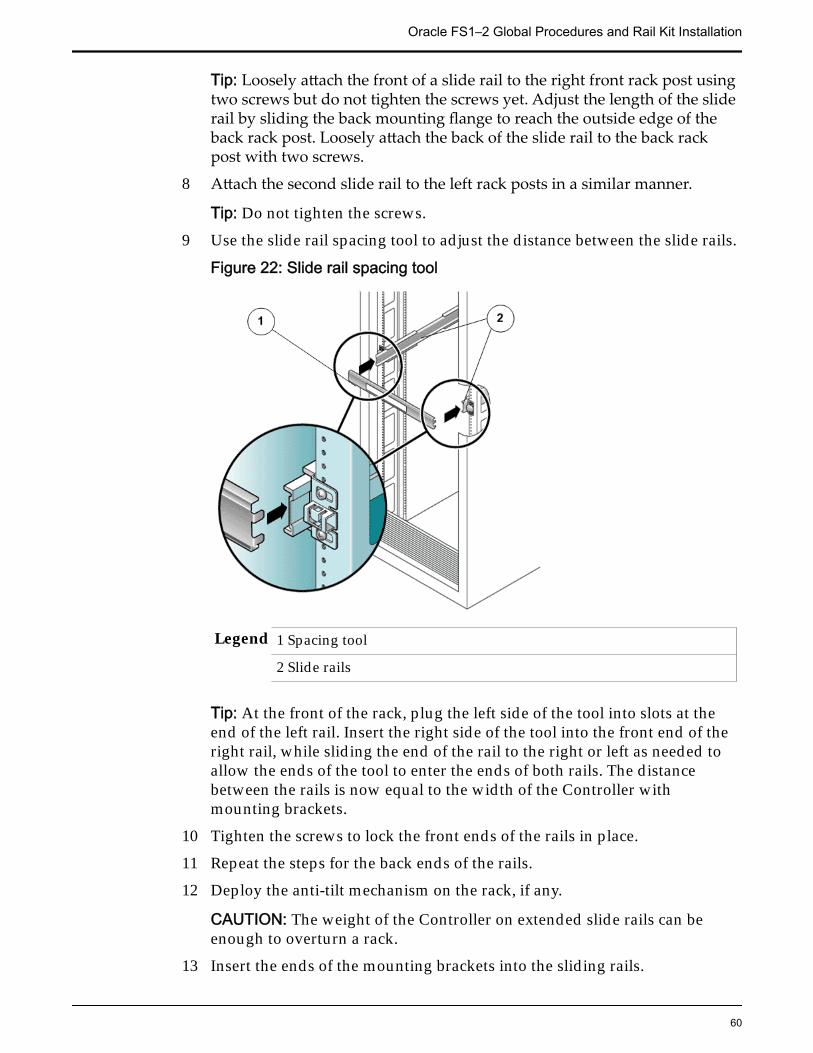
Tip: Loosely attach the front of a slide rail to the right front rack post usingtwo screws but do not tighten the screws yet. Adjust the length of the sliderail by sliding the back mounting flange to reach the outside edge of theback rack post. Loosely attach the back of the slide rail to the back rackpost with two screws.
8 Attach the second slide rail to the left rack posts in a similar manner.
Tip: Do not tighten the screws.
9 Use the slide rail spacing tool to adjust the distance between the slide rails.
Figure 22: Slide rail spacing tool
Legend 1 Spacing tool
2 Slide rails
Tip: At the front of the rack, plug the left side of the tool into slots at theend of the left rail. Insert the right side of the tool into the front end of theright rail, while sliding the end of the rail to the right or left as needed toallow the ends of the tool to enter the ends of both rails. The distancebetween the rails is now equal to the width of the Controller withmounting brackets.
10 Tighten the screws to lock the front ends of the rails in place.
11 Repeat the steps for the back ends of the rails.
12 Deploy the anti-tilt mechanism on the rack, if any.
CAUTION: The weight of the Controller on extended slide rails can beenough to overturn a rack.
13 Insert the ends of the mounting brackets into the sliding rails.
Oracle FS1–2 Global Procedures and Rail Kit Installation
60
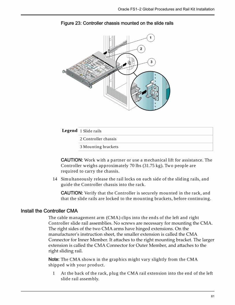
Figure 23: Controller chassis mounted on the slide rails
Legend 1 Slide rails
2 Controller chassis
3 Mounting brackets
CAUTION: Work with a partner or use a mechanical lift for assistance. TheController weighs approximately 70 lbs (31.75 kg). Two people arerequired to carry the chassis.
14 Simultaneously release the rail locks on each side of the sliding rails, andguide the Controller chassis into the rack.
CAUTION: Verify that the Controller is securely mounted in the rack, andthat the slide rails are locked to the mounting brackets, before continuing.
Install the Controller CMAThe cable management arm (CMA) clips into the ends of the left and rightController slide rail assemblies. No screws are necessary for mounting the CMA.The right sides of the two CMA arms have hinged extensions. On themanufacturer's instruction sheet, the smaller extension is called the CMAConnector for Inner Member. It attaches to the right mounting bracket. The largerextension is called the CMA Connector for Outer Member, and attaches to theright sliding rail.
Note: The CMA shown in the graphics might vary slightly from the CMAshipped with your product.
1 At the back of the rack, plug the CMA rail extension into the end of the leftslide rail assembly.
Oracle FS1–2 Global Procedures and Rail Kit Installation
61
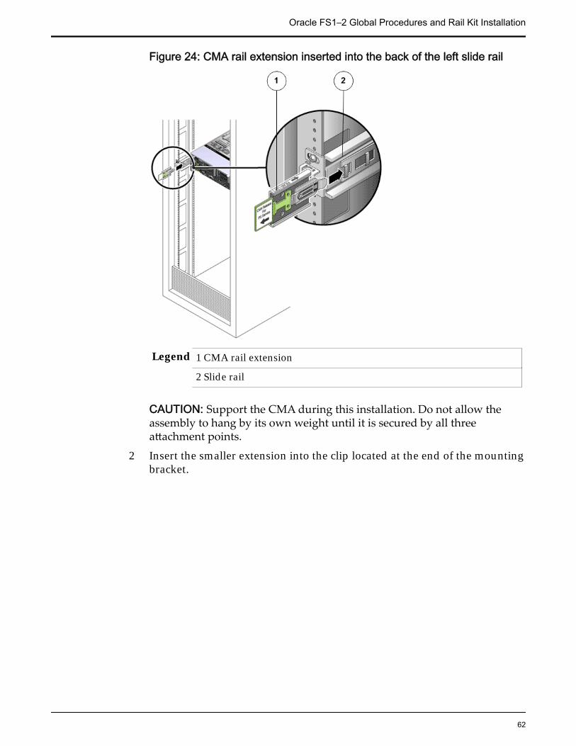
Figure 24: CMA rail extension inserted into the back of the left slide rail
Legend 1 CMA rail extension
2 Slide rail
CAUTION: Support the CMA during this installation. Do not allow theassembly to hang by its own weight until it is secured by all threeattachment points.
2 Insert the smaller extension into the clip located at the end of the mountingbracket.
Oracle FS1–2 Global Procedures and Rail Kit Installation
62
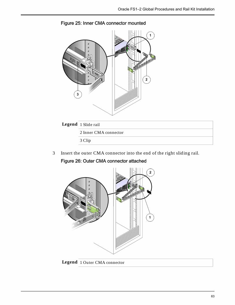
Figure 25: Inner CMA connector mounted
Legend 1 Slide rail
2 Inner CMA connector
3 Clip
3 Insert the outer CMA connector into the end of the right sliding rail.
Figure 26: Outer CMA connector attached
Legend 1 Outer CMA connector
Oracle FS1–2 Global Procedures and Rail Kit Installation
63
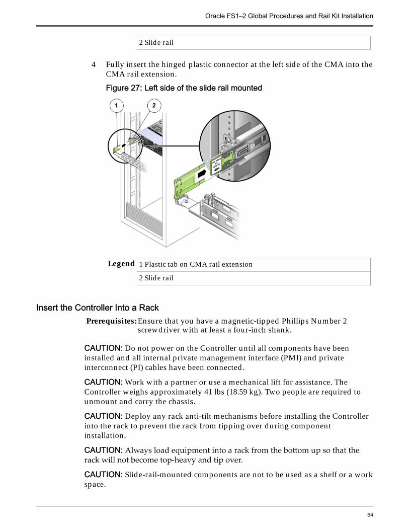
2 Slide rail
4 Fully insert the hinged plastic connector at the left side of the CMA into theCMA rail extension.
Figure 27: Left side of the slide rail mounted
Legend 1 Plastic tab on CMA rail extension
2 Slide rail
Insert the Controller Into a RackPrerequisites: Ensure that you have a magnetic-tipped Phillips Number 2
screwdriver with at least a four-inch shank.
CAUTION: Do not power on the Controller until all components have beeninstalled and all internal private management interface (PMI) and privateinterconnect (PI) cables have been connected.
CAUTION: Work with a partner or use a mechanical lift for assistance. TheController weighs approximately 41 lbs (18.59 kg). Two people are required tounmount and carry the chassis.
CAUTION: Deploy any rack anti-tilt mechanisms before installing the Controllerinto the rack to prevent the rack from tipping over during componentinstallation.
CAUTION: Always load equipment into a rack from the bottom up so that therack will not become top-heavy and tip over.
CAUTION: Slide-rail-mounted components are not to be used as a shelf or a workspace.
Oracle FS1–2 Global Procedures and Rail Kit Installation
64
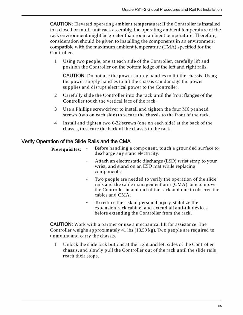
CAUTION: Elevated operating ambient temperature: If the Controller is installedin a closed or multi-unit rack assembly, the operating ambient temperature of therack environment might be greater than room ambient temperature. Therefore,consideration should be given to installing the components in an environmentcompatible with the maximum ambient temperature (TMA) specified for theController.
1 Using two people, one at each side of the Controller, carefully lift andposition the Controller on the bottom ledge of the left and right rails.
CAUTION: Do not use the power supply handles to lift the chassis. Usingthe power supply handles to lift the chassis can damage the powersupplies and disrupt electrical power to the Controller.
2 Carefully slide the Controller into the rack until the front flanges of theController touch the vertical face of the rack.
3 Use a Phillips screwdriver to install and tighten the four M6 panheadscrews (two on each side) to secure the chassis to the front of the rack.
4 Install and tighten two 6-32 screws (one on each side) at the back of thechassis, to secure the back of the chassis to the rack.
Verify Operation of the Slide Rails and the CMAPrerequisites: • Before handling a component, touch a grounded surface to
discharge any static electricity.• Attach an electrostatic discharge (ESD) wrist strap to your
wrist, and stand on an ESD mat while replacingcomponents.
• Two people are needed to verify the operation of the sliderails and the cable management arm (CMA): one to movethe Controller in and out of the rack and one to observe thecables and CMA.
• To reduce the risk of personal injury, stabilize theexpansion rack cabinet and extend all anti-tilt devicesbefore extending the Controller from the rack.
CAUTION: Work with a partner or use a mechanical lift for assistance. TheController weighs approximately 41 lbs (18.59 kg). Two people are required tounmount and carry the chassis.
1 Unlock the slide lock buttons at the right and left sides of the Controllerchassis, and slowly pull the Controller out of the rack until the slide railsreach their stops.
Oracle FS1–2 Global Procedures and Rail Kit Installation
65
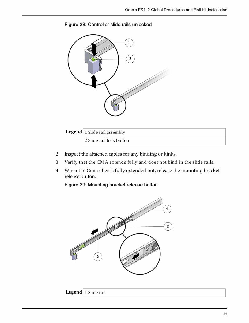
Figure 28: Controller slide rails unlocked
Legend 1 Slide rail assembly
2 Slide rail lock button
2 Inspect the attached cables for any binding or kinks.
3 Verify that the CMA extends fully and does not bind in the slide rails.
4 When the Controller is fully extended out, release the mounting bracketrelease button.
Figure 29: Mounting bracket release button
Legend 1 Slide rail
Oracle FS1–2 Global Procedures and Rail Kit Installation
66
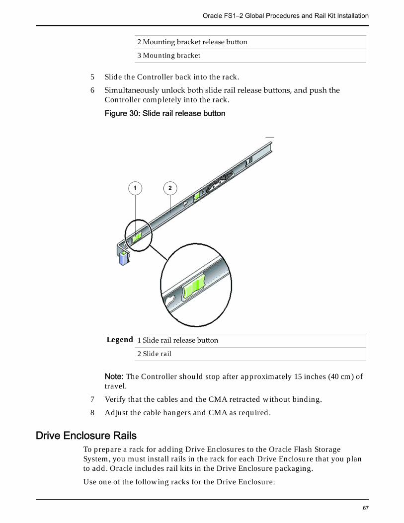
2 Mounting bracket release button
3 Mounting bracket
5 Slide the Controller back into the rack.6 Simultaneously unlock both slide rail release buttons, and push the
Controller completely into the rack.
Figure 30: Slide rail release button
Legend 1 Slide rail release button
2 Slide rail
Note: The Controller should stop after approximately 15 inches (40 cm) oftravel.
7 Verify that the cables and the CMA retracted without binding.8 Adjust the cable hangers and CMA as required.
Drive Enclosure RailsTo prepare a rack for adding Drive Enclosures to the Oracle Flash StorageSystem, you must install rails in the rack for each Drive Enclosure that you planto add. Oracle includes rail kits in the Drive Enclosure packaging.
Use one of the following racks for the Drive Enclosure:
Oracle FS1–2 Global Procedures and Rail Kit Installation
67
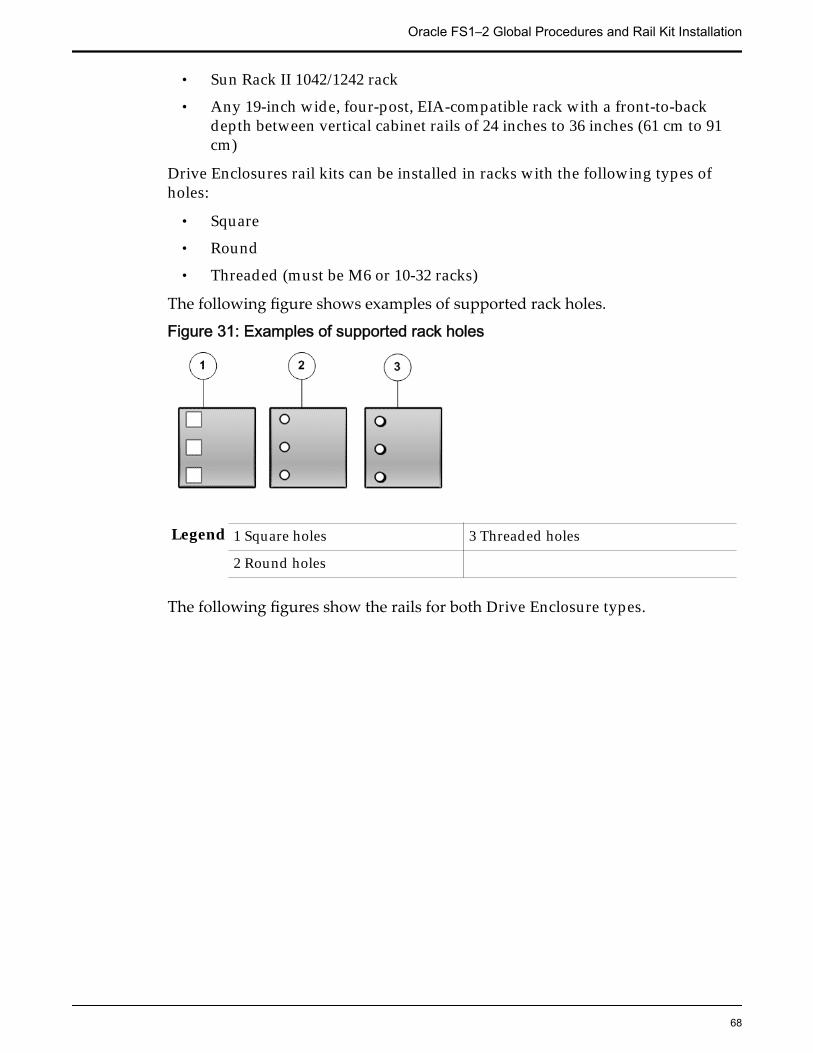
• Sun Rack II 1042/1242 rack
• Any 19-inch wide, four-post, EIA-compatible rack with a front-to-backdepth between vertical cabinet rails of 24 inches to 36 inches (61 cm to 91cm)
Drive Enclosures rail kits can be installed in racks with the following types ofholes:
• Square
• Round
• Threaded (must be M6 or 10-32 racks)
The following figure shows examples of supported rack holes.
Figure 31: Examples of supported rack holes
Legend 1 Square holes 3 Threaded holes
2 Round holes
The following figures show the rails for both Drive Enclosure types.
Oracle FS1–2 Global Procedures and Rail Kit Installation
68
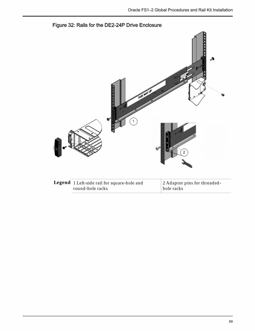
Figure 32: Rails for the DE2-24P Drive Enclosure
Legend 1 Left-side rail for square-hole andround-hole racks
2 Adaptor pins for threaded-hole racks
Oracle FS1–2 Global Procedures and Rail Kit Installation
69
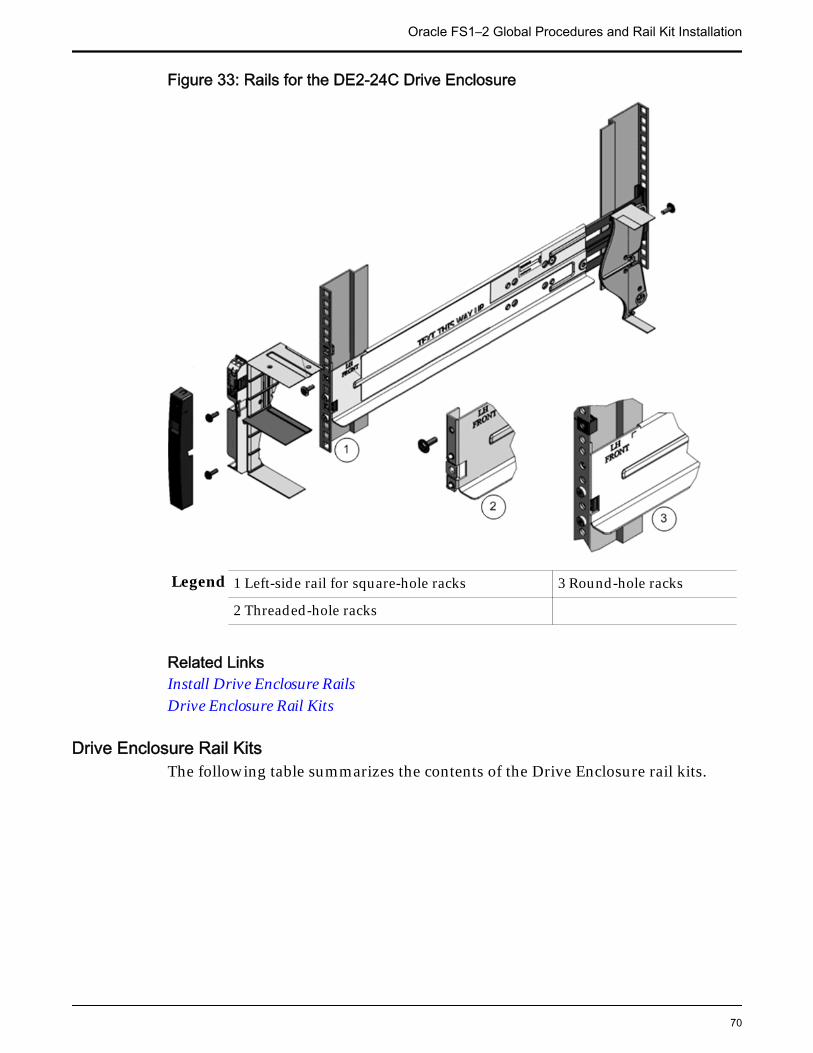
Figure 33: Rails for the DE2-24C Drive Enclosure
Legend 1 Left-side rail for square-hole racks 3 Round-hole racks
2 Threaded-hole racks
Related LinksInstall Drive Enclosure RailsDrive Enclosure Rail Kits
Drive Enclosure Rail KitsThe following table summarizes the contents of the Drive Enclosure rail kits.
Oracle FS1–2 Global Procedures and Rail Kit Installation
70
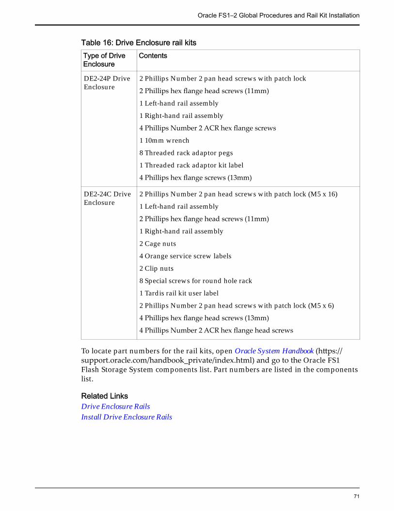
Table 16: Drive Enclosure rail kitsType of DriveEnclosure
Contents
DE2-24P DriveEnclosure
2 Phillips Number 2 pan head screws with patch lock
2 Phillips hex flange head screws (11mm)
1 Left-hand rail assembly
1 Right-hand rail assembly
4 Phillips Number 2 ACR hex flange screws
1 10mm wrench
8 Threaded rack adaptor pegs
1 Threaded rack adaptor kit label
4 Phillips hex flange screws (13mm)
DE2-24C DriveEnclosure
2 Phillips Number 2 pan head screws with patch lock (M5 x 16)
1 Left-hand rail assembly
2 Phillips hex flange head screws (11mm)
1 Right-hand rail assembly
2 Cage nuts
4 Orange service screw labels
2 Clip nuts
8 Special screws for round hole rack
1 Tardis rail kit user label
2 Phillips Number 2 pan head screws with patch lock (M5 x 6)
4 Phillips hex flange head screws (13mm)
4 Phillips Number 2 ACR hex flange head screws
To locate part numbers for the rail kits, open Oracle System Handbook (https://support.oracle.com/handbook_private/index.html) and go to the Oracle FS1Flash Storage System components list. Part numbers are listed in the componentslist.
Related LinksDrive Enclosure RailsInstall Drive Enclosure Rails
Oracle FS1–2 Global Procedures and Rail Kit Installation
71
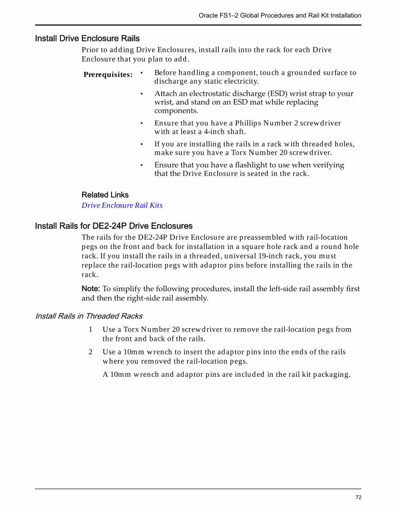
Install Drive Enclosure RailsPrior to adding Drive Enclosures, install rails into the rack for each DriveEnclosure that you plan to add.
Prerequisites: • Before handling a component, touch a grounded surface todischarge any static electricity.
• Attach an electrostatic discharge (ESD) wrist strap to yourwrist, and stand on an ESD mat while replacingcomponents.
• Ensure that you have a Phillips Number 2 screwdriverwith at least a 4-inch shaft.
• If you are installing the rails in a rack with threaded holes,make sure you have a Torx Number 20 screwdriver.
• Ensure that you have a flashlight to use when verifyingthat the Drive Enclosure is seated in the rack.
Related LinksDrive Enclosure Rail Kits
Install Rails for DE2-24P Drive EnclosuresThe rails for the DE2-24P Drive Enclosure are preassembled with rail-locationpegs on the front and back for installation in a square hole rack and a round holerack. If you install the rails in a threaded, universal 19-inch rack, you mustreplace the rail-location pegs with adaptor pins before installing the rails in therack.
Note: To simplify the following procedures, install the left-side rail assembly firstand then the right-side rail assembly.
Install Rails in Threaded Racks1 Use a Torx Number 20 screwdriver to remove the rail-location pegs from
the front and back of the rails.
2 Use a 10mm wrench to insert the adaptor pins into the ends of the railswhere you removed the rail-location pegs.
A 10mm wrench and adaptor pins are included in the rail kit packaging.
Oracle FS1–2 Global Procedures and Rail Kit Installation
72
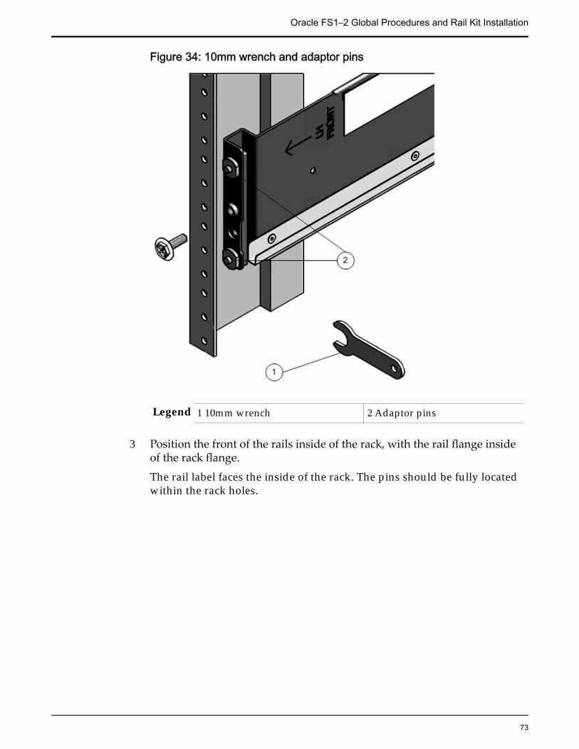
Figure 34: 10mm wrench and adaptor pins
Legend 1 10mm wrench 2 Adaptor pins
3 Position the front of the rails inside of the rack, with the rail flange insideof the rack flange.
The rail label faces the inside of the rack. The pins should be fully locatedwithin the rack holes.
Oracle FS1–2 Global Procedures and Rail Kit Installation
73
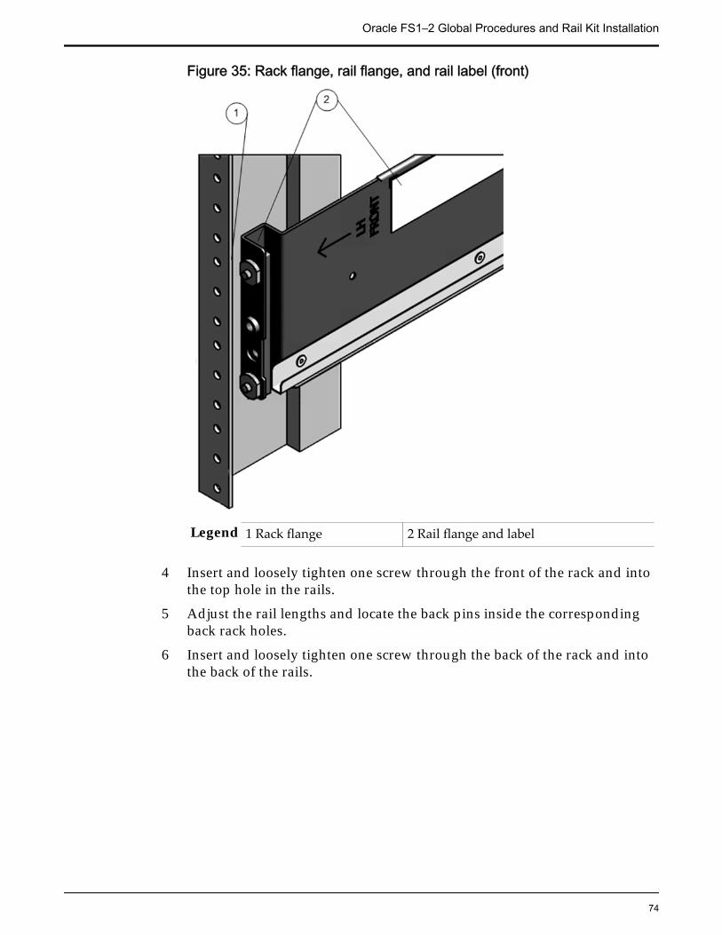
Figure 35: Rack flange, rail flange, and rail label (front)
Legend 1 Rack flange 2 Rail flange and label
4 Insert and loosely tighten one screw through the front of the rack and intothe top hole in the rails.
5 Adjust the rail lengths and locate the back pins inside the correspondingback rack holes.
6 Insert and loosely tighten one screw through the back of the rack and intothe back of the rails.
Oracle FS1–2 Global Procedures and Rail Kit Installation
74
Figure 36: Back-mounting screw
Install Rails in Square or Round Hole Racks1 Locate the appropriate rack unit (RU) height.
The DE2-24P Drive Enclosure requires two standard mounting units (2U)of vertical space in the rack.
2 Remove the rails from the Drive Enclosure packaging.
3 Position the front rail-location pegs fully inside the holes in the front rackposts where you plan to add a Drive Enclosure.
Make sure the rail label faces the inside of the rack. Align the rail flangeinside of the rack flange. Position the rail-location pegs fully within therack holes.
Oracle FS1–2 Global Procedures and Rail Kit Installation
75
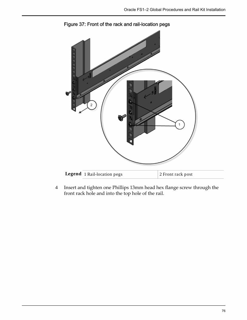
Figure 37: Front of the rack and rail-location pegs
Legend 1 Rail-location pegs 2 Front rack post
4 Insert and tighten one Phillips 13mm head hex flange screw through thefront rack hole and into the top hole of the rail.
Oracle FS1–2 Global Procedures and Rail Kit Installation
76
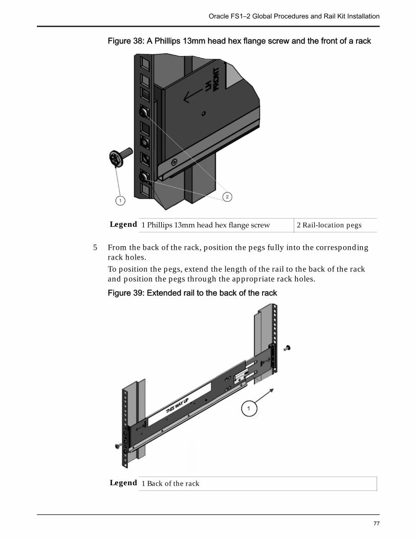
Figure 38: A Phillips 13mm head hex flange screw and the front of a rack
Legend 1 Phillips 13mm head hex flange screw 2 Rail-location pegs
5 From the back of the rack, position the pegs fully into the correspondingrack holes.To position the pegs, extend the length of the rail to the back of the rackand position the pegs through the appropriate rack holes.
Figure 39: Extended rail to the back of the rack
Legend 1 Back of the rack
Oracle FS1–2 Global Procedures and Rail Kit Installation
77
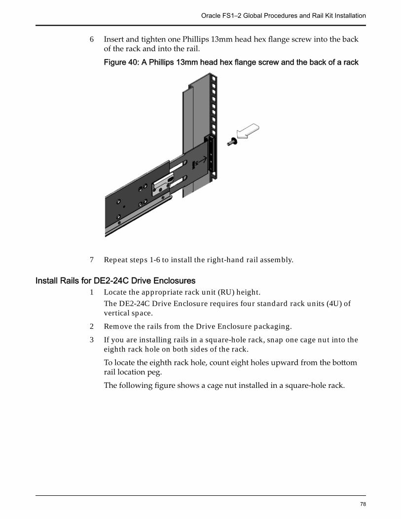
6 Insert and tighten one Phillips 13mm head hex flange screw into the backof the rack and into the rail.
Figure 40: A Phillips 13mm head hex flange screw and the back of a rack
7 Repeat steps 1-6 to install the right-hand rail assembly.
Install Rails for DE2-24C Drive Enclosures1 Locate the appropriate rack unit (RU) height.
The DE2-24C Drive Enclosure requires four standard rack units (4U) ofvertical space.
2 Remove the rails from the Drive Enclosure packaging.
3 If you are installing rails in a square-hole rack, snap one cage nut into theeighth rack hole on both sides of the rack.
To locate the eighth rack hole, count eight holes upward from the bottomrail location peg.
The following figure shows a cage nut installed in a square-hole rack.
Oracle FS1–2 Global Procedures and Rail Kit Installation
78
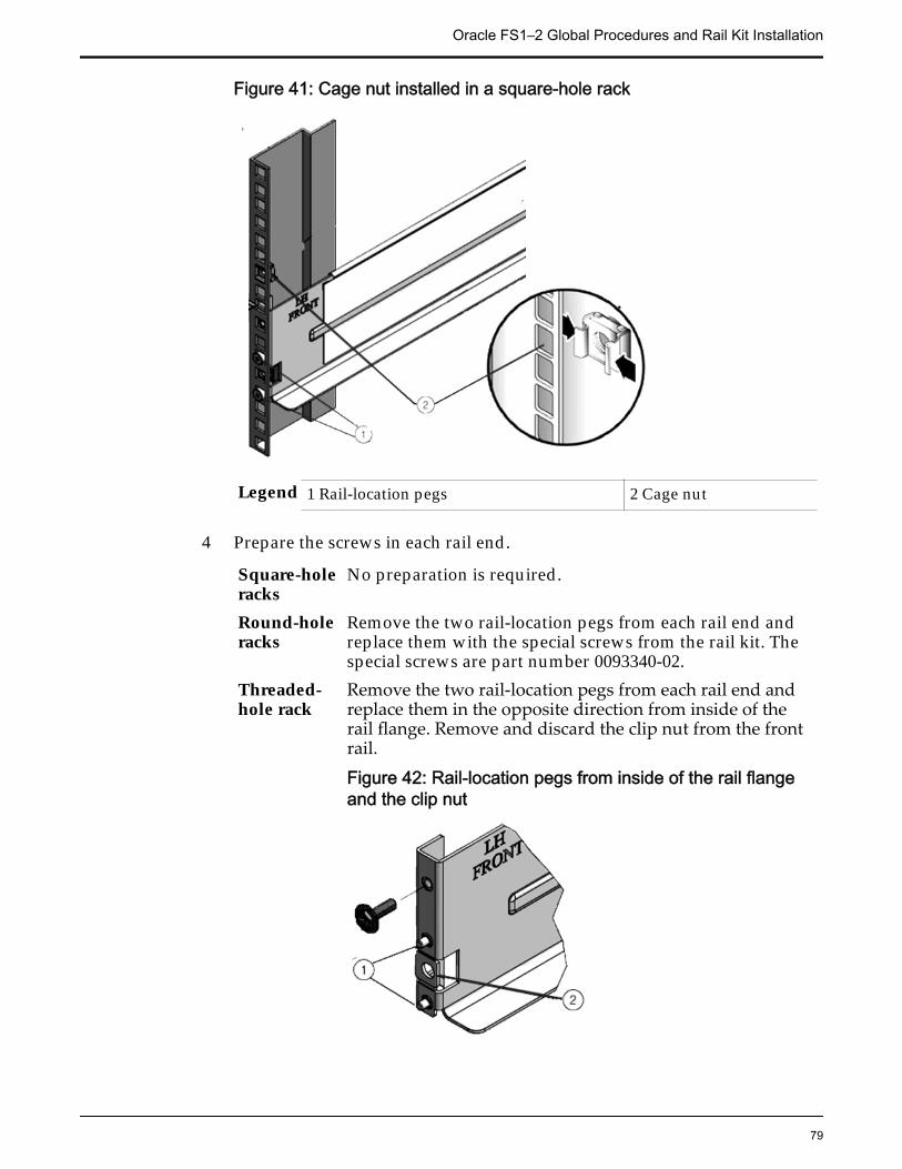
Figure 41: Cage nut installed in a square-hole rack
Legend 1 Rail-location pegs 2 Cage nut
4 Prepare the screws in each rail end.
Square-holeracks
No preparation is required.
Round-holeracks
Remove the two rail-location pegs from each rail end andreplace them with the special screws from the rail kit. Thespecial screws are part number 0093340-02.
Threaded-hole rack
Remove the two rail-location pegs from each rail end andreplace them in the opposite direction from inside of therail flange. Remove and discard the clip nut from the frontrail.
Figure 42: Rail-location pegs from inside of the rail flangeand the clip nut
Oracle FS1–2 Global Procedures and Rail Kit Installation
79
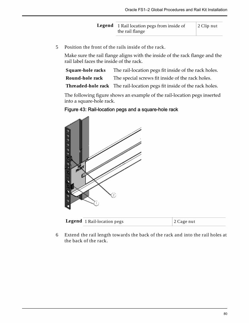
Legend 1 Rail location pegs from inside ofthe rail flange
2 Clip nut
5 Position the front of the rails inside of the rack.
Make sure the rail flange aligns with the inside of the rack flange and therail label faces the inside of the rack.
Square-hole racks The rail-location pegs fit inside of the rack holes.Round-hole rack The special screws fit inside of the rack holes.Threaded-hole rack The rail-location pegs fit inside of the rack holes.
The following figure shows an example of the rail-location pegs insertedinto a square-hole rack.
Figure 43: Rail-location pegs and a square-hole rack
Legend 1 Rail-location pegs 2 Cage nut
6 Extend the rail length towards the back of the rack and into the rail holes atthe back of the rack.
Oracle FS1–2 Global Procedures and Rail Kit Installation
80
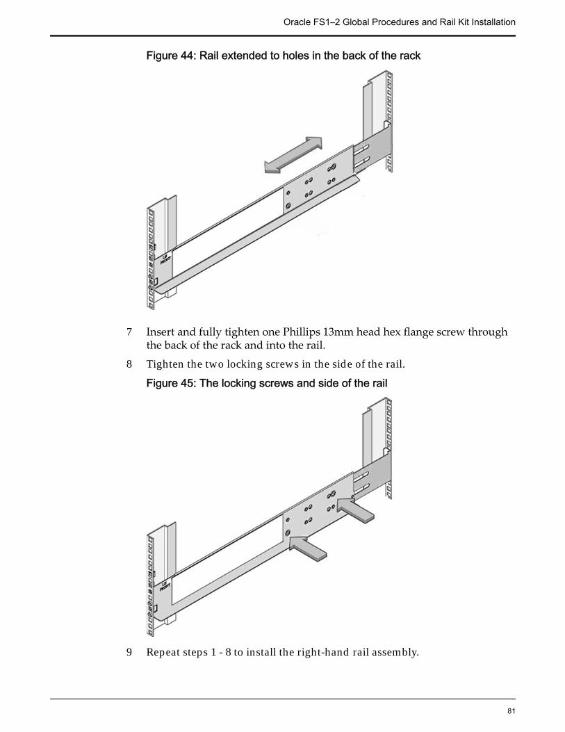
Figure 44: Rail extended to holes in the back of the rack
7 Insert and fully tighten one Phillips 13mm head hex flange screw throughthe back of the rack and into the rail.
8 Tighten the two locking screws in the side of the rail.
Figure 45: The locking screws and side of the rail
9 Repeat steps 1 - 8 to install the right-hand rail assembly.
Oracle FS1–2 Global Procedures and Rail Kit Installation
81
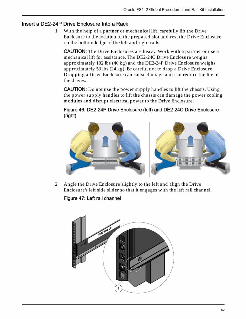
Insert a DE2-24P Drive Enclosure Into a Rack1 With the help of a partner or mechanical lift, carefully lift the Drive
Enclosure to the location of the prepared slot and rest the Drive Enclosureon the bottom ledge of the left and right rails.
CAUTION: The Drive Enclosures are heavy. Work with a partner or use amechanical lift for assistance. The DE2-24C Drive Enclosure weighsapproximately 102 lbs (46 kg) and the DE2-24P Drive Enclosure weighsapproximately 53 lbs (24 kg). Be careful not to drop a Drive Enclosure.Dropping a Drive Enclosure can cause damage and can reduce the life ofthe drives.
CAUTION: Do not use the power supply handles to lift the chassis. Usingthe power supply handles to lift the chassis can damage the power coolingmodules and disrupt electrical power to the Drive Enclosure.
Figure 46: DE2-24P Drive Enclosure (left) and DE2-24C Drive Enclosure(right)
2 Angle the Drive Enclosure slightly to the left and align the DriveEnclosure’s left side slider so that it engages with the left rail channel.
Figure 47: Left rail channel
Oracle FS1–2 Global Procedures and Rail Kit Installation
82
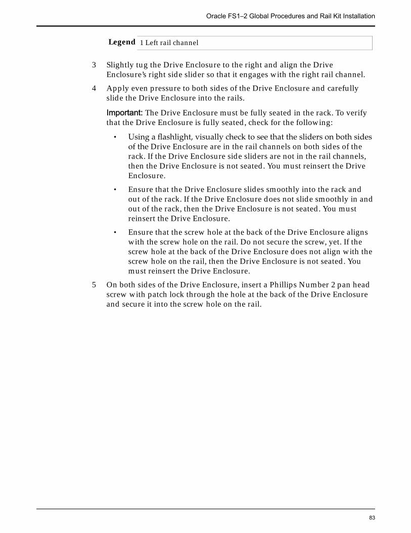
Legend 1 Left rail channel
3 Slightly tug the Drive Enclosure to the right and align the DriveEnclosure’s right side slider so that it engages with the right rail channel.
4 Apply even pressure to both sides of the Drive Enclosure and carefullyslide the Drive Enclosure into the rails.
Important: The Drive Enclosure must be fully seated in the rack. To verifythat the Drive Enclosure is fully seated, check for the following:
• Using a flashlight, visually check to see that the sliders on both sidesof the Drive Enclosure are in the rail channels on both sides of therack. If the Drive Enclosure side sliders are not in the rail channels,then the Drive Enclosure is not seated. You must reinsert the DriveEnclosure.
• Ensure that the Drive Enclosure slides smoothly into the rack andout of the rack. If the Drive Enclosure does not slide smoothly in andout of the rack, then the Drive Enclosure is not seated. You mustreinsert the Drive Enclosure.
• Ensure that the screw hole at the back of the Drive Enclosure alignswith the screw hole on the rail. Do not secure the screw, yet. If thescrew hole at the back of the Drive Enclosure does not align with thescrew hole on the rail, then the Drive Enclosure is not seated. Youmust reinsert the Drive Enclosure.
5 On both sides of the Drive Enclosure, insert a Phillips Number 2 pan headscrew with patch lock through the hole at the back of the Drive Enclosureand secure it into the screw hole on the rail.
Oracle FS1–2 Global Procedures and Rail Kit Installation
83
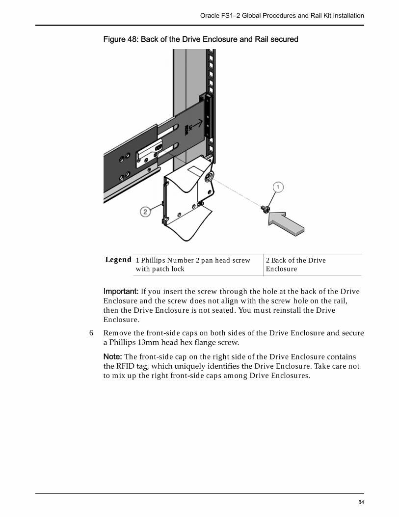
Figure 48: Back of the Drive Enclosure and Rail secured
Legend 1 Phillips Number 2 pan head screwwith patch lock
2 Back of the DriveEnclosure
Important: If you insert the screw through the hole at the back of the DriveEnclosure and the screw does not align with the screw hole on the rail,then the Drive Enclosure is not seated. You must reinstall the DriveEnclosure.
6 Remove the front-side caps on both sides of the Drive Enclosure and securea Phillips 13mm head hex flange screw.
Note: The front-side cap on the right side of the Drive Enclosure containsthe RFID tag, which uniquely identifies the Drive Enclosure. Take care notto mix up the right front-side caps among Drive Enclosures.
Oracle FS1–2 Global Procedures and Rail Kit Installation
84
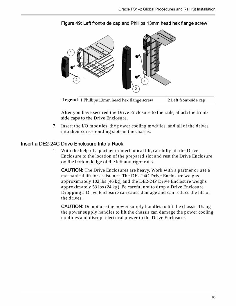
Figure 49: Left front-side cap and Phillips 13mm head hex flange screw
Legend 1 Phillips 13mm head hex flange screw 2 Left front-side cap
After you have secured the Drive Enclosure to the rails, attach the front-side caps to the Drive Enclosure.
7 Insert the I/O modules, the power cooling modules, and all of the drivesinto their corresponding slots in the chassis.
Insert a DE2-24C Drive Enclosure Into a Rack1 With the help of a partner or mechanical lift, carefully lift the Drive
Enclosure to the location of the prepared slot and rest the Drive Enclosureon the bottom ledge of the left and right rails.
CAUTION: The Drive Enclosures are heavy. Work with a partner or use amechanical lift for assistance. The DE2-24C Drive Enclosure weighsapproximately 102 lbs (46 kg) and the DE2-24P Drive Enclosure weighsapproximately 53 lbs (24 kg). Be careful not to drop a Drive Enclosure.Dropping a Drive Enclosure can cause damage and can reduce the life ofthe drives.
CAUTION: Do not use the power supply handles to lift the chassis. Usingthe power supply handles to lift the chassis can damage the power coolingmodules and disrupt electrical power to the Drive Enclosure.
Oracle FS1–2 Global Procedures and Rail Kit Installation
85
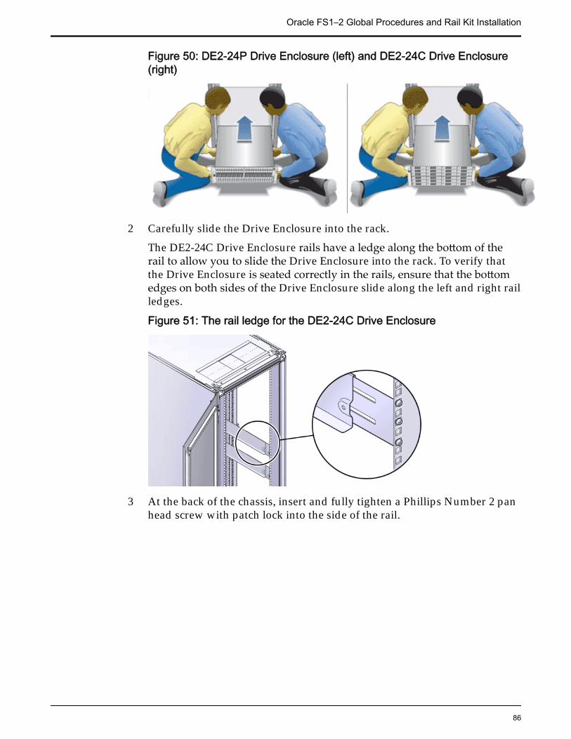
Figure 50: DE2-24P Drive Enclosure (left) and DE2-24C Drive Enclosure(right)
2 Carefully slide the Drive Enclosure into the rack.
The DE2-24C Drive Enclosure rails have a ledge along the bottom of therail to allow you to slide the Drive Enclosure into the rack. To verify thatthe Drive Enclosure is seated correctly in the rails, ensure that the bottomedges on both sides of the Drive Enclosure slide along the left and right railledges.
Figure 51: The rail ledge for the DE2-24C Drive Enclosure
3 At the back of the chassis, insert and fully tighten a Phillips Number 2 panhead screw with patch lock into the side of the rail.
Oracle FS1–2 Global Procedures and Rail Kit Installation
86
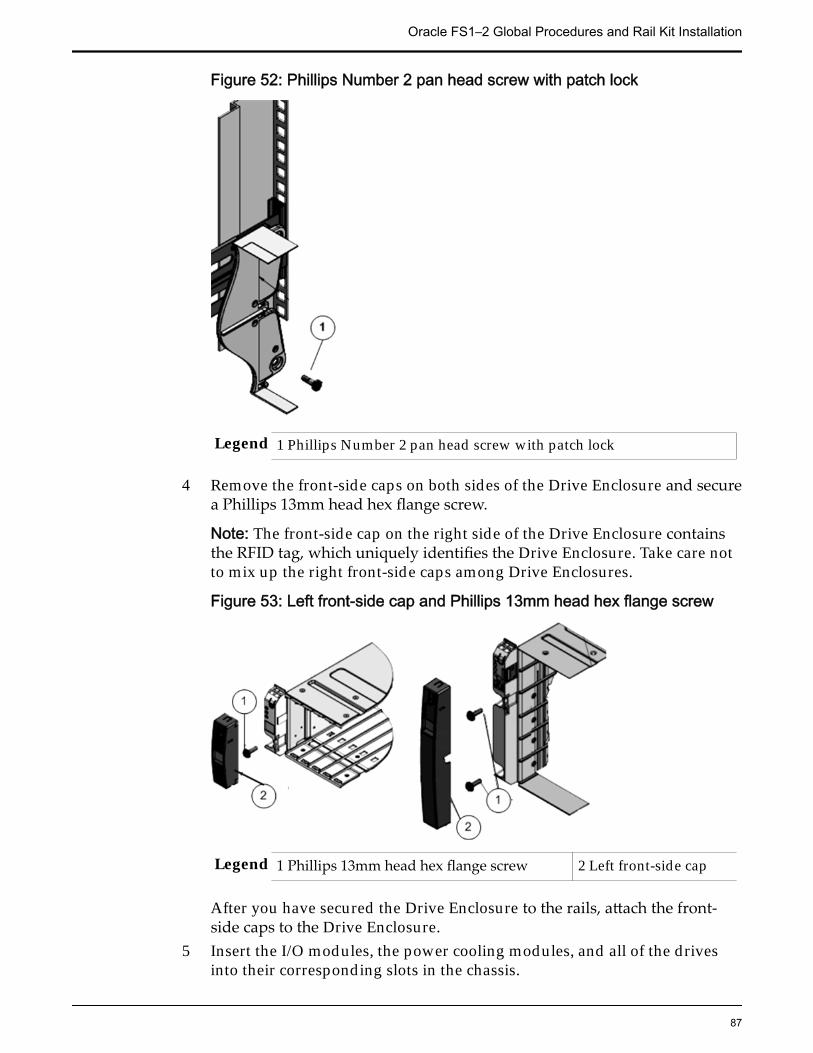
Figure 52: Phillips Number 2 pan head screw with patch lock
Legend 1 Phillips Number 2 pan head screw with patch lock
4 Remove the front-side caps on both sides of the Drive Enclosure and securea Phillips 13mm head hex flange screw.
Note: The front-side cap on the right side of the Drive Enclosure containsthe RFID tag, which uniquely identifies the Drive Enclosure. Take care notto mix up the right front-side caps among Drive Enclosures.
Figure 53: Left front-side cap and Phillips 13mm head hex flange screw
Legend 1 Phillips 13mm head hex flange screw 2 Left front-side cap
After you have secured the Drive Enclosure to the rails, attach the front-side caps to the Drive Enclosure.
5 Insert the I/O modules, the power cooling modules, and all of the drivesinto their corresponding slots in the chassis.
Oracle FS1–2 Global Procedures and Rail Kit Installation
87
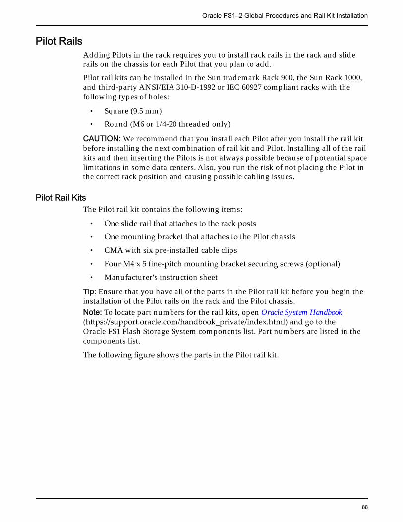
Pilot RailsAdding Pilots in the rack requires you to install rack rails in the rack and sliderails on the chassis for each Pilot that you plan to add.
Pilot rail kits can be installed in the Sun trademark Rack 900, the Sun Rack 1000,and third-party ANSI/EIA 310-D-1992 or IEC 60927 compliant racks with thefollowing types of holes:
• Square (9.5 mm)
• Round (M6 or 1/4-20 threaded only)
CAUTION: We recommend that you install each Pilot after you install the rail kitbefore installing the next combination of rail kit and Pilot. Installing all of the railkits and then inserting the Pilots is not always possible because of potential spacelimitations in some data centers. Also, you run the risk of not placing the Pilot inthe correct rack position and causing possible cabling issues.
Pilot Rail KitsThe Pilot rail kit contains the following items:
• One slide rail that attaches to the rack posts
• One mounting bracket that attaches to the Pilot chassis
• CMA with six pre-installed cable clips
• Four M4 x 5 fine-pitch mounting bracket securing screws (optional)
• Manufacturer's instruction sheet
Tip: Ensure that you have all of the parts in the Pilot rail kit before you begin theinstallation of the Pilot rails on the rack and the Pilot chassis.Note: To locate part numbers for the rail kits, open Oracle System Handbook(https://support.oracle.com/handbook_private/index.html) and go to theOracle FS1 Flash Storage System components list. Part numbers are listed in thecomponents list.
The following figure shows the parts in the Pilot rail kit.
Oracle FS1–2 Global Procedures and Rail Kit Installation
88
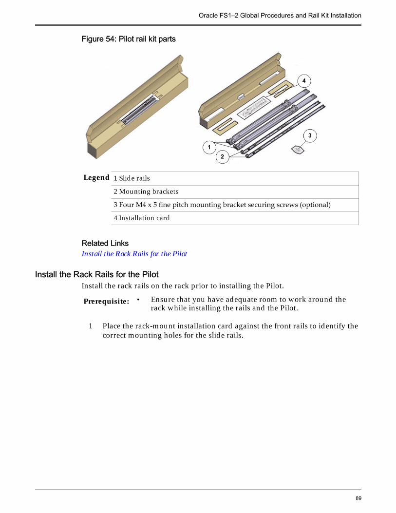
Figure 54: Pilot rail kit parts
Legend 1 Slide rails
2 Mounting brackets
3 Four M4 x 5 fine pitch mounting bracket securing screws (optional)
4 Installation card
Related LinksInstall the Rack Rails for the Pilot
Install the Rack Rails for the PilotInstall the rack rails on the rack prior to installing the Pilot.
Prerequisite: • Ensure that you have adequate room to work around therack while installing the rails and the Pilot.
1 Place the rack-mount installation card against the front rails to identify thecorrect mounting holes for the slide rails.
Oracle FS1–2 Global Procedures and Rail Kit Installation
89
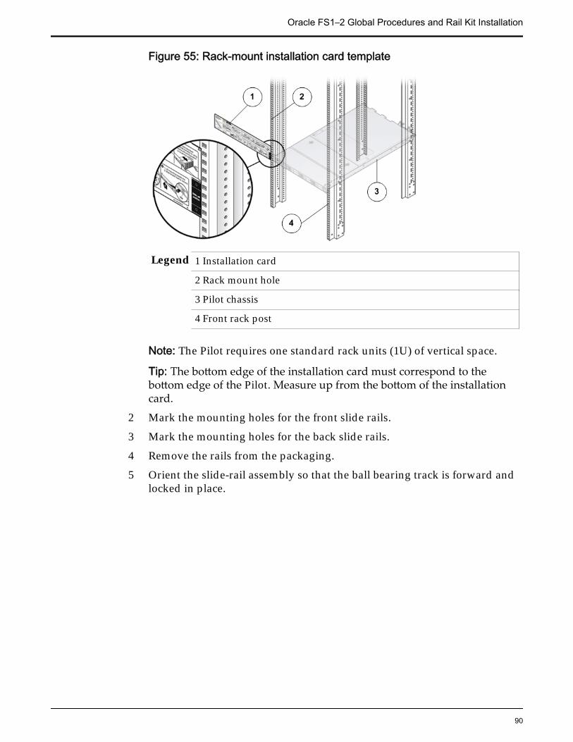
Figure 55: Rack-mount installation card template
Legend 1 Installation card
2 Rack mount hole
3 Pilot chassis
4 Front rack post
Note: The Pilot requires one standard rack units (1U) of vertical space.
Tip: The bottom edge of the installation card must correspond to thebottom edge of the Pilot. Measure up from the bottom of the installationcard.
2 Mark the mounting holes for the front slide rails.
3 Mark the mounting holes for the back slide rails.
4 Remove the rails from the packaging.
5 Orient the slide-rail assembly so that the ball bearing track is forward andlocked in place.
Oracle FS1–2 Global Procedures and Rail Kit Installation
90
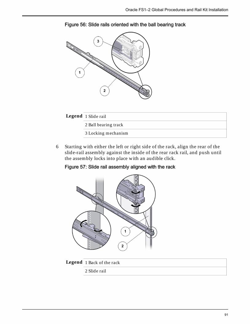
Figure 56: Slide rails oriented with the ball bearing track
Legend 1 Slide rail
2 Ball bearing track
3 Locking mechanism
6 Starting with either the left or right side of the rack, align the rear of theslide-rail assembly against the inside of the rear rack rail, and push untilthe assembly locks into place with an audible click.
Figure 57: Slide rail assembly aligned with the rack
Legend 1 Back of the rack
2 Slide rail
Oracle FS1–2 Global Procedures and Rail Kit Installation
91
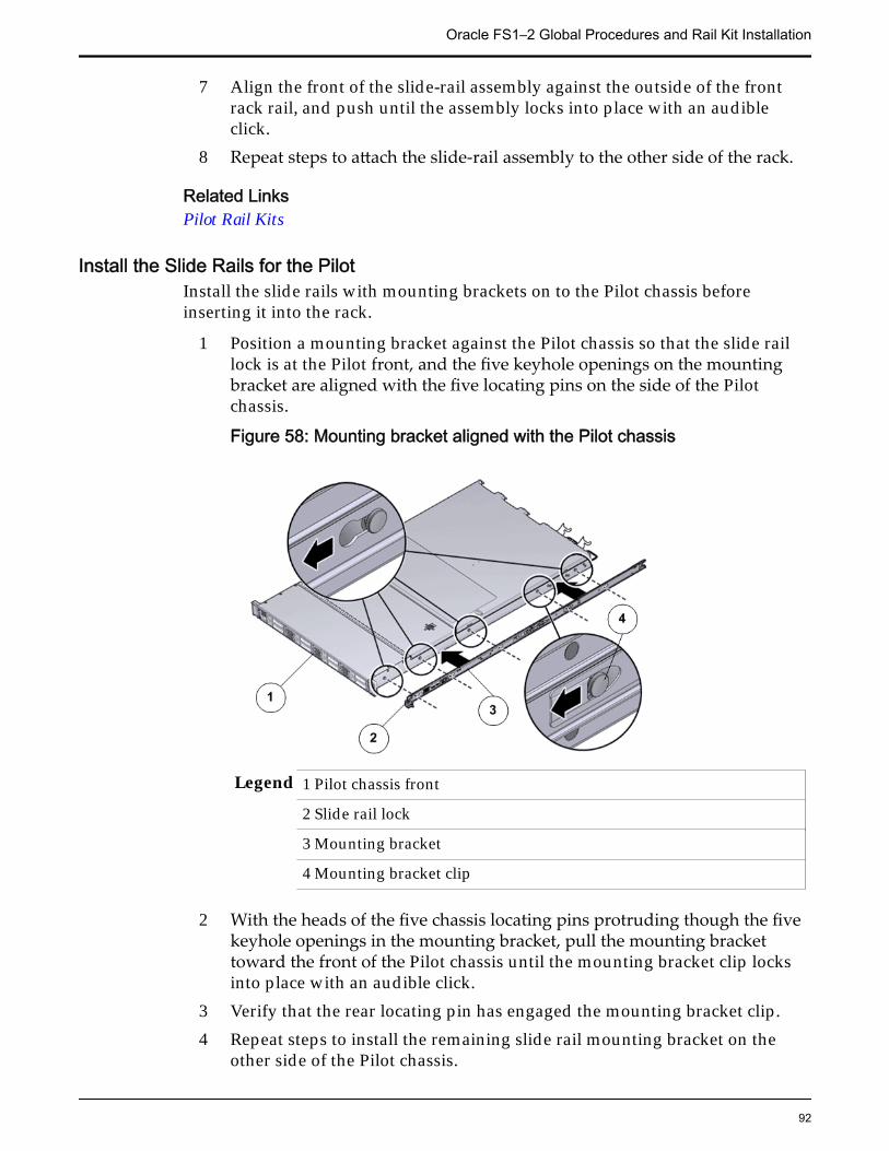
7 Align the front of the slide-rail assembly against the outside of the frontrack rail, and push until the assembly locks into place with an audibleclick.
8 Repeat steps to attach the slide-rail assembly to the other side of the rack.
Related LinksPilot Rail Kits
Install the Slide Rails for the PilotInstall the slide rails with mounting brackets on to the Pilot chassis beforeinserting it into the rack.
1 Position a mounting bracket against the Pilot chassis so that the slide raillock is at the Pilot front, and the five keyhole openings on the mountingbracket are aligned with the five locating pins on the side of the Pilotchassis.
Figure 58: Mounting bracket aligned with the Pilot chassis
Legend 1 Pilot chassis front
2 Slide rail lock
3 Mounting bracket
4 Mounting bracket clip
2 With the heads of the five chassis locating pins protruding though the fivekeyhole openings in the mounting bracket, pull the mounting brackettoward the front of the Pilot chassis until the mounting bracket clip locksinto place with an audible click.
3 Verify that the rear locating pin has engaged the mounting bracket clip.4 Repeat steps to install the remaining slide rail mounting bracket on the
other side of the Pilot chassis.
Oracle FS1–2 Global Procedures and Rail Kit Installation
92
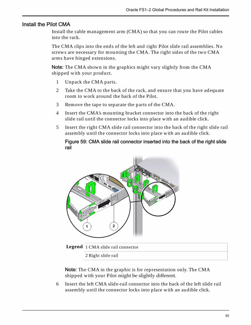
Install the Pilot CMAInstall the cable management arm (CMA) so that you can route the Pilot cablesinto the rack.
The CMA clips into the ends of the left and right Pilot slide rail assemblies. Noscrews are necessary for mounting the CMA. The right sides of the two CMAarms have hinged extensions.
Note: The CMA shown in the graphics might vary slightly from the CMAshipped with your product.
1 Unpack the CMA parts.
2 Take the CMA to the back of the rack, and ensure that you have adequateroom to work around the back of the Pilot.
3 Remove the tape to separate the parts of the CMA.
4 Insert the CMA’s mounting bracket connector into the back of the rightslide rail until the connector locks into place with an audible click.
5 Insert the right CMA slide rail connector into the back of the right slide railassembly until the connector locks into place with an audible click.
Figure 59: CMA slide rail connector inserted into the back of the right sliderail
Legend 1 CMA slide rail connector
2 Right slide rail
Note: The CMA in the graphic is for representation only. The CMAshipped with your Pilot might be slightly different.
6 Insert the left CMA slide-rail connector into the back of the left slide railassembly until the connector locks into place with an audible click.
Oracle FS1–2 Global Procedures and Rail Kit Installation
93
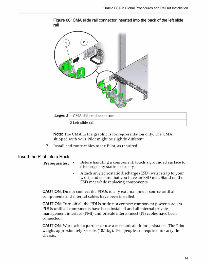
Figure 60: CMA slide rail connector inserted into the back of the left sliderail
Legend 1 CMA slide rail connector
2 Left slide rail
Note: The CMA in the graphic is for representation only. The CMAshipped with your Pilot might be slightly different.
7 Install and route cables to the Pilot, as required.
Insert the Pilot into a RackPrerequisites: • Before handling a component, touch a grounded surface to
discharge any static electricity.• Attach an electrostatic discharge (ESD) wrist strap to your
wrist, and ensure that you have an ESD mat. Stand on theESD mat while replacing components
CAUTION: Do not connect the PDUs to any external power source until allcomponents and internal cables have been installed.
CAUTION: Turn off all the PDUs or do not connect component power cords toPDUs until all components have been installed and all internal privatemanagement interface (PMI) and private interconnect (PI) cables have beenconnected.
CAUTION: Work with a partner or use a mechanical lift for assistance. The Pilotweighs approximately 39.9 lbs (18.1 kg). Two people are required to carry thechassis.
Oracle FS1–2 Global Procedures and Rail Kit Installation
94
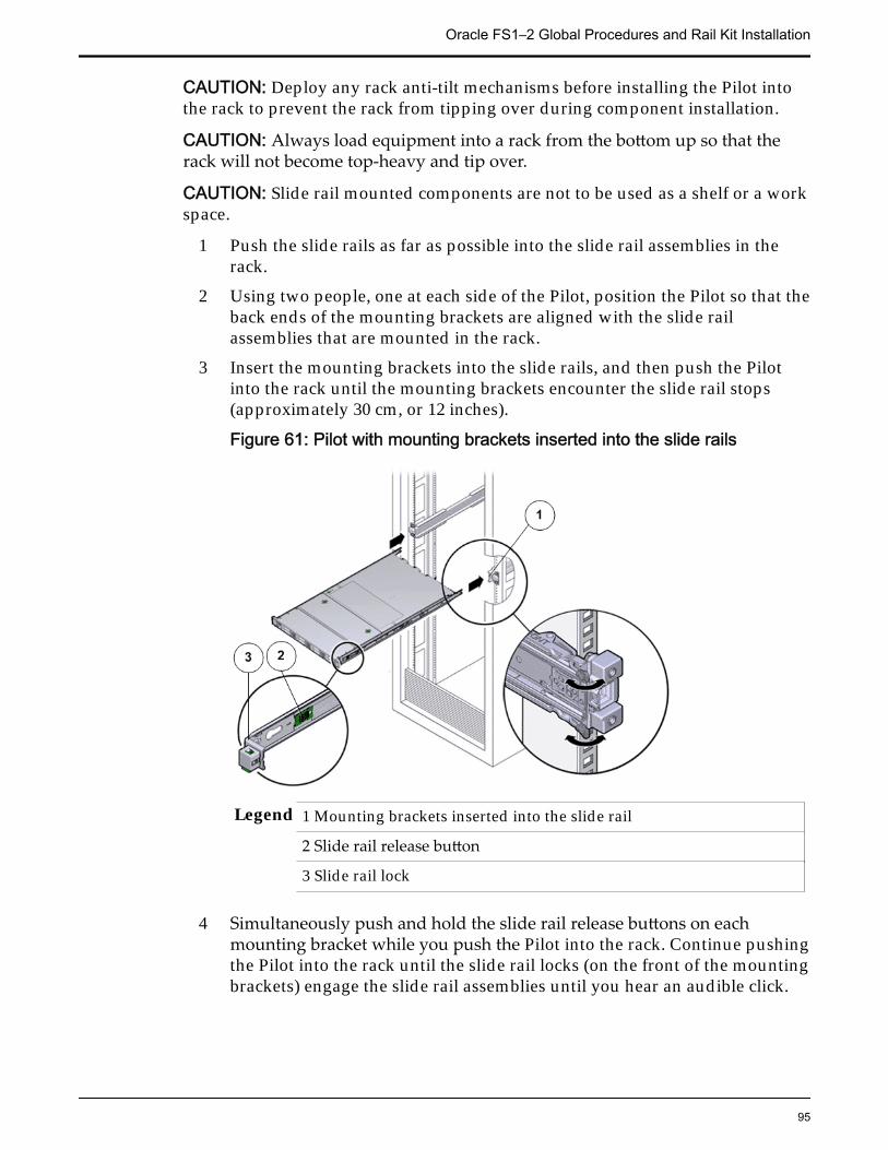
CAUTION: Deploy any rack anti-tilt mechanisms before installing the Pilot intothe rack to prevent the rack from tipping over during component installation.
CAUTION: Always load equipment into a rack from the bottom up so that therack will not become top-heavy and tip over.
CAUTION: Slide rail mounted components are not to be used as a shelf or a workspace.
1 Push the slide rails as far as possible into the slide rail assemblies in therack.
2 Using two people, one at each side of the Pilot, position the Pilot so that theback ends of the mounting brackets are aligned with the slide railassemblies that are mounted in the rack.
3 Insert the mounting brackets into the slide rails, and then push the Pilotinto the rack until the mounting brackets encounter the slide rail stops(approximately 30 cm, or 12 inches).
Figure 61: Pilot with mounting brackets inserted into the slide rails
Legend 1 Mounting brackets inserted into the slide rail
2 Slide rail release button
3 Slide rail lock
4 Simultaneously push and hold the slide rail release buttons on eachmounting bracket while you push the Pilot into the rack. Continue pushingthe Pilot into the rack until the slide rail locks (on the front of the mountingbrackets) engage the slide rail assemblies until you hear an audible click.
Oracle FS1–2 Global Procedures and Rail Kit Installation
95
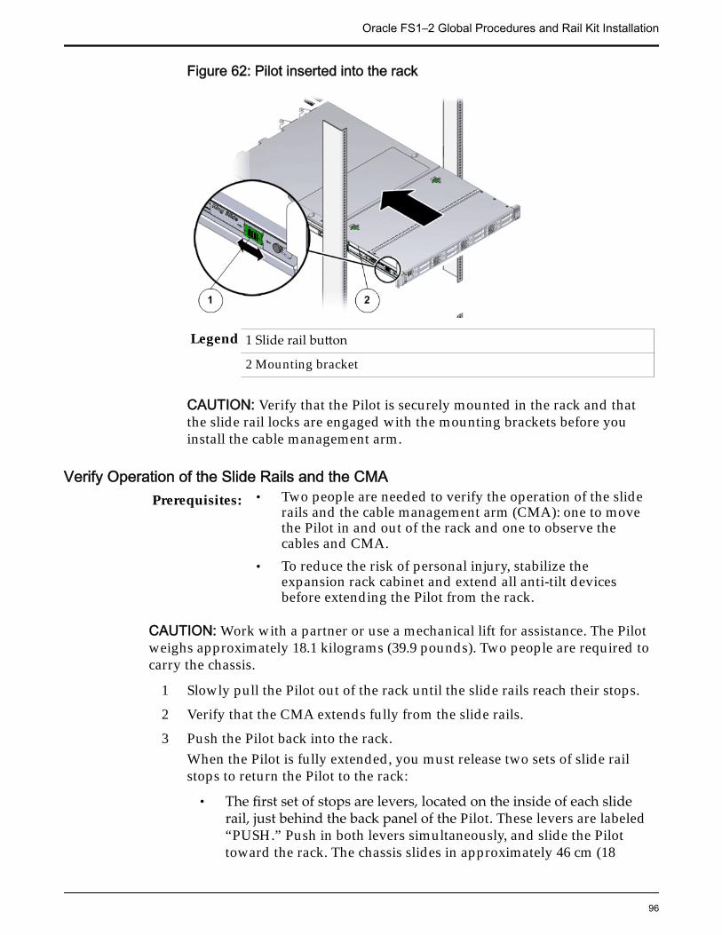
Figure 62: Pilot inserted into the rack
Legend 1 Slide rail button
2 Mounting bracket
CAUTION: Verify that the Pilot is securely mounted in the rack and thatthe slide rail locks are engaged with the mounting brackets before youinstall the cable management arm.
Verify Operation of the Slide Rails and the CMAPrerequisites: • Two people are needed to verify the operation of the slide
rails and the cable management arm (CMA): one to movethe Pilot in and out of the rack and one to observe thecables and CMA.
• To reduce the risk of personal injury, stabilize theexpansion rack cabinet and extend all anti-tilt devicesbefore extending the Pilot from the rack.
CAUTION: Work with a partner or use a mechanical lift for assistance. The Pilotweighs approximately 18.1 kilograms (39.9 pounds). Two people are required tocarry the chassis.
1 Slowly pull the Pilot out of the rack until the slide rails reach their stops.
2 Verify that the CMA extends fully from the slide rails.
3 Push the Pilot back into the rack.When the Pilot is fully extended, you must release two sets of slide railstops to return the Pilot to the rack:
• The first set of stops are levers, located on the inside of each sliderail, just behind the back panel of the Pilot. These levers are labeled“PUSH.” Push in both levers simultaneously, and slide the Pilottoward the rack. The chassis slides in approximately 46 cm (18
Oracle FS1–2 Global Procedures and Rail Kit Installation
96

inches) and stops. Verify that the cables and the CMA retract withoutbinding before you continue.
• The second set of stops are the slide rail release buttons, located nearthe front of each mounting bracket. Simultaneously push both of thegreen slide-rail release buttons, and push the Pilot completely intothe rack until both slide-rail locks engage.
4 Adjust the cable straps and CMA, as required.
Oracle FS1–2 Global Procedures and Rail Kit Installation
97
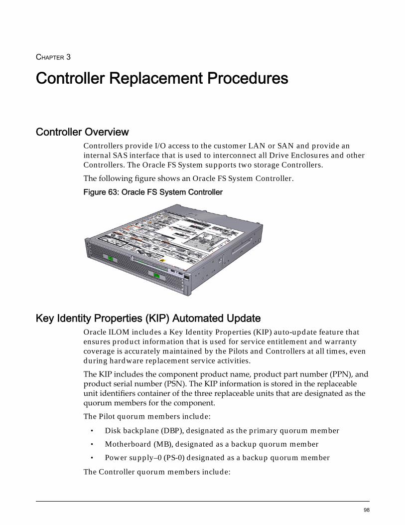
CHAPTER 3
Controller Replacement Procedures
Controller OverviewControllers provide I/O access to the customer LAN or SAN and provide aninternal SAS interface that is used to interconnect all Drive Enclosures and otherControllers. The Oracle FS System supports two storage Controllers.
The following figure shows an Oracle FS System Controller.
Figure 63: Oracle FS System Controller
Key Identity Properties (KIP) Automated UpdateOracle ILOM includes a Key Identity Properties (KIP) auto-update feature thatensures product information that is used for service entitlement and warrantycoverage is accurately maintained by the Pilots and Controllers at all times, evenduring hardware replacement service activities.
The KIP includes the component product name, product part number (PPN), andproduct serial number (PSN). The KIP information is stored in the replaceableunit identifiers container of the three replaceable units that are designated as thequorum members for the component.
The Pilot quorum members include:
• Disk backplane (DBP), designated as the primary quorum member
• Motherboard (MB), designated as a backup quorum member
• Power supply–0 (PS-0) designated as a backup quorum member
The Controller quorum members include:
98
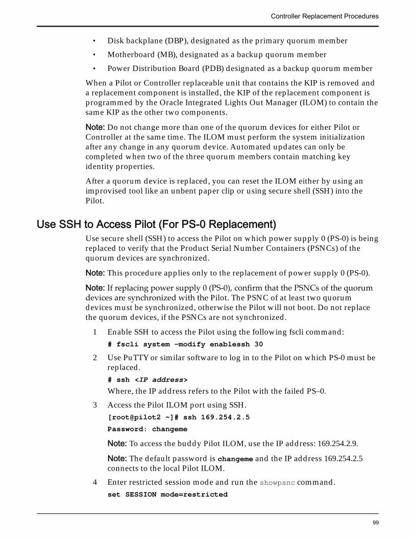
• Disk backplane (DBP), designated as the primary quorum member
• Motherboard (MB), designated as a backup quorum member
• Power Distribution Board (PDB) designated as a backup quorum member
When a Pilot or Controller replaceable unit that contains the KIP is removed anda replacement component is installed, the KIP of the replacement component isprogrammed by the Oracle Integrated Lights Out Manager (ILOM) to contain thesame KIP as the other two components.
Note: Do not change more than one of the quorum devices for either Pilot orController at the same time. The ILOM must perform the system initializationafter any change in any quorum device. Automated updates can only becompleted when two of the three quorum members contain matching keyidentity properties.
After a quorum device is replaced, you can reset the ILOM either by using animprovised tool like an unbent paper clip or using secure shell (SSH) into thePilot.
Use SSH to Access Pilot (For PS-0 Replacement)Use secure shell (SSH) to access the Pilot on which power supply 0 (PS-0) is beingreplaced to verify that the Product Serial Number Containers (PSNCs) of thequorum devices are synchronized.
Note: This procedure applies only to the replacement of power supply 0 (PS-0).
Note: If replacing power supply 0 (PS-0), confirm that the PSNCs of the quorumdevices are synchronized with the Pilot. The PSNC of at least two quorumdevices must be synchronized, otherwise the Pilot will not boot. Do not replacethe quorum devices, if the PSNCs are not synchronized.
1 Enable SSH to access the Pilot using the following fscli command:# fscli system -modify enablessh 30
2 Use PuTTY or similar software to log in to the Pilot on which PS-0 must bereplaced.# ssh <IP address>Where, the IP address refers to the Pilot with the failed PS–0.
3 Access the Pilot ILOM port using SSH.[root@pilot2 ~]# ssh 169.254.2.5Password: changemeNote: To access the buddy Pilot ILOM, use the IP address: 169.254.2.9.
Note: The default password is changeme and the IP address 169.254.2.5connects to the local Pilot ILOM.
4 Enter restricted session mode and run the showpsnc command.set SESSION mode=restricted
Controller Replacement Procedures
99
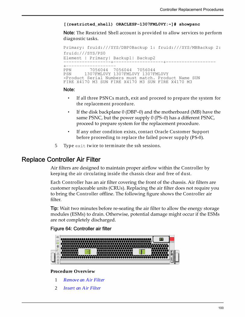
[(restricted_shell) ORACLESP-1307FML0VY:~]# showpsncNote: The Restricted Shell account is provided to allow services to performdiagnostic tasks.
Primary: fruid:///SYS/DBP0Backup 1: fruid:///SYS/MBBackup 2:fruid:///SYS/PS0Element | Primary| Backup1| Backup2------------------+-------------------+-------------------+-------------------PPN 7056044 7056044 7056044PSN 1307FML0VY 1307FML0VY 1307FML0VY<Product Serial Numbers must match. Product Name SUNFIRE X4170 M3 SUN FIRE X4170 M3 SUN FIRE X4170 M3Note:
• If all three PSNCs match, exit and proceed to prepare the system forthe replacement procedure.
• If the disk backplane 0 (DBP–0) and the motherboard (MB) have thesame PSNC, but the power supply 0 (PS–0) has a different PSNC,proceed to prepare system for the replacement procedure.
• If any other condition exists, contact Oracle Customer Supportbefore proceeding to replace the failed power supply (PS-0).
5 Type exit twice to terminate the ssh sessions.
Replace Controller Air FilterAir filters are designed to maintain proper airflow within the Controller bykeeping the air circulating inside the chassis clear and free of dust.
Each Controller has an air filter covering the front of the chassis. Air filters arecustomer replaceable units (CRUs). Replacing the air filter does not require youto bring the Controller offline. The following figure shows the Controller airfilter.
Tip: Wait two minutes before re-seating the air filter to allow the energy storagemodules (ESMs) to drain. Otherwise, potential damage might occur if the ESMsare not completely discharged.
Figure 64: Controller air filter
Procedure Overview
1 Remove an Air Filter
2 Insert an Air Filter
Controller Replacement Procedures
100
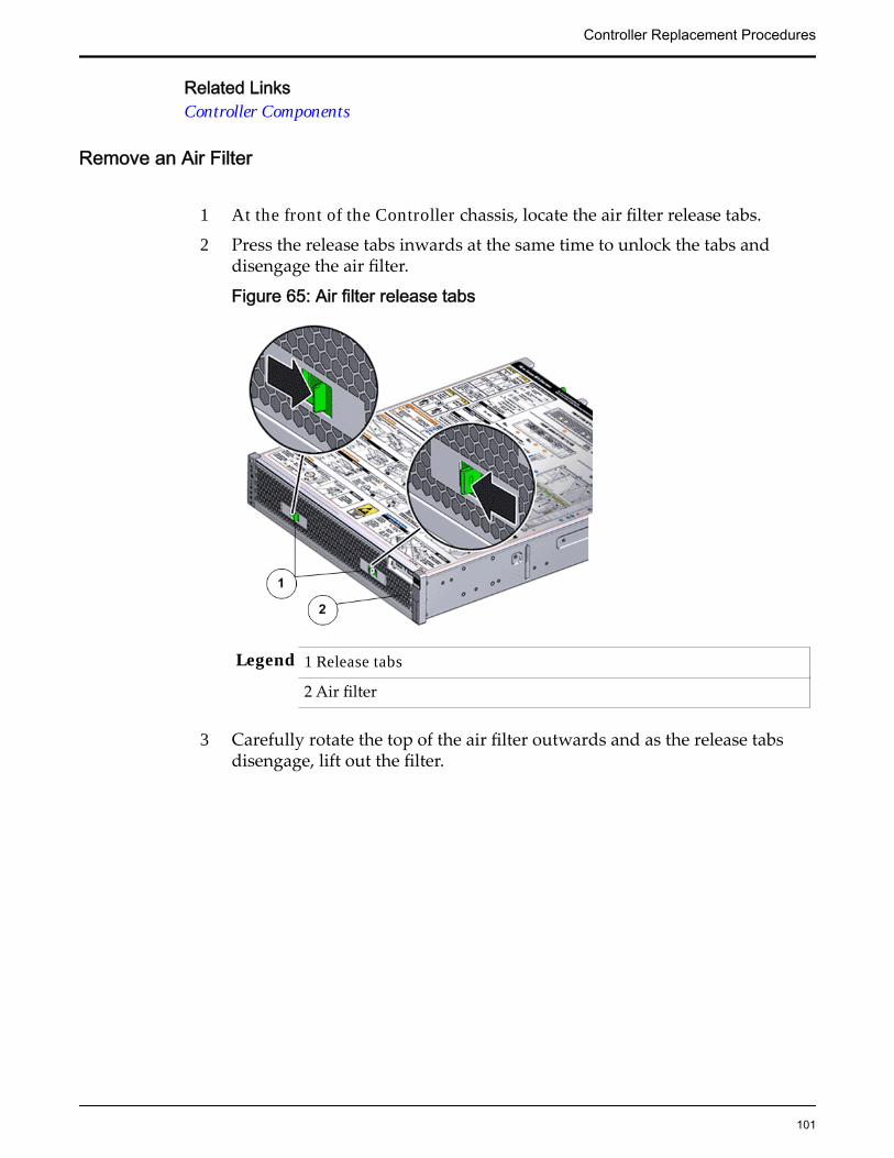
Related LinksController Components
Remove an Air Filter
1 At the front of the Controller chassis, locate the air filter release tabs.
2 Press the release tabs inwards at the same time to unlock the tabs anddisengage the air filter.
Figure 65: Air filter release tabs
Legend 1 Release tabs
2 Air filter
3 Carefully rotate the top of the air filter outwards and as the release tabsdisengage, lift out the filter.
Controller Replacement Procedures
101
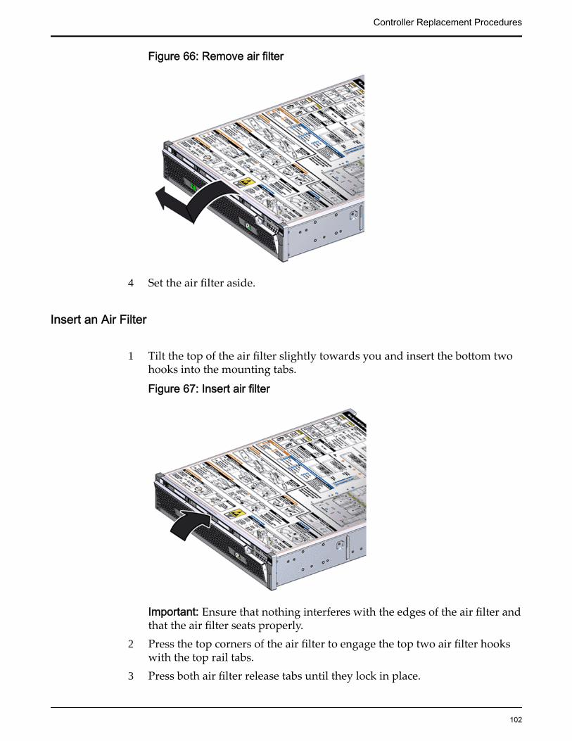
Figure 66: Remove air filter
4 Set the air filter aside.
Insert an Air Filter
1 Tilt the top of the air filter slightly towards you and insert the bottom twohooks into the mounting tabs.
Figure 67: Insert air filter
Important: Ensure that nothing interferes with the edges of the air filter andthat the air filter seats properly.
2 Press the top corners of the air filter to engage the top two air filter hookswith the top rail tabs.
3 Press both air filter release tabs until they lock in place.
Controller Replacement Procedures
102
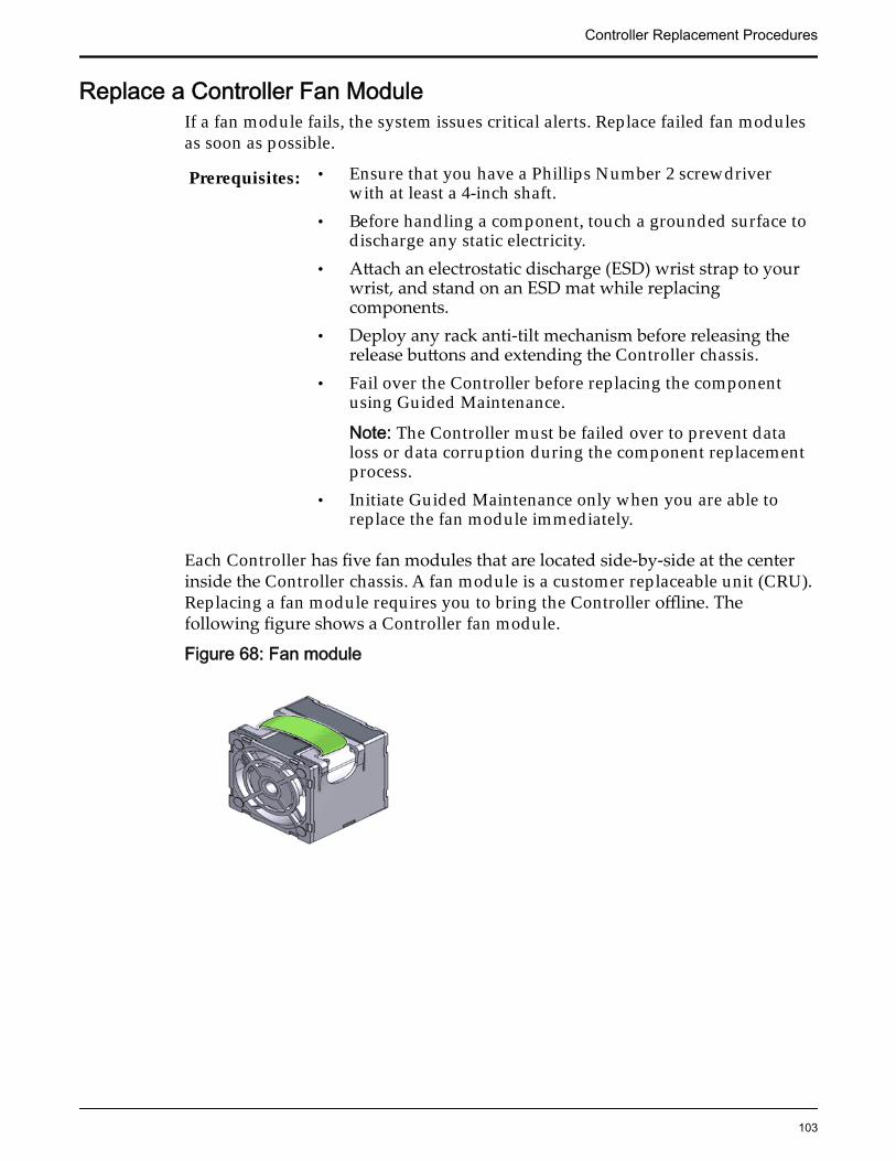
Replace a Controller Fan ModuleIf a fan module fails, the system issues critical alerts. Replace failed fan modulesas soon as possible.
Prerequisites: • Ensure that you have a Phillips Number 2 screwdriverwith at least a 4-inch shaft.
• Before handling a component, touch a grounded surface todischarge any static electricity.
• Attach an electrostatic discharge (ESD) wrist strap to yourwrist, and stand on an ESD mat while replacingcomponents.
• Deploy any rack anti-tilt mechanism before releasing therelease buttons and extending the Controller chassis.
• Fail over the Controller before replacing the componentusing Guided Maintenance.
Note: The Controller must be failed over to prevent dataloss or data corruption during the component replacementprocess.
• Initiate Guided Maintenance only when you are able toreplace the fan module immediately.
Each Controller has five fan modules that are located side-by-side at the centerinside the Controller chassis. A fan module is a customer replaceable unit (CRU).Replacing a fan module requires you to bring the Controller offline. Thefollowing figure shows a Controller fan module.
Figure 68: Fan module
Controller Replacement Procedures
103
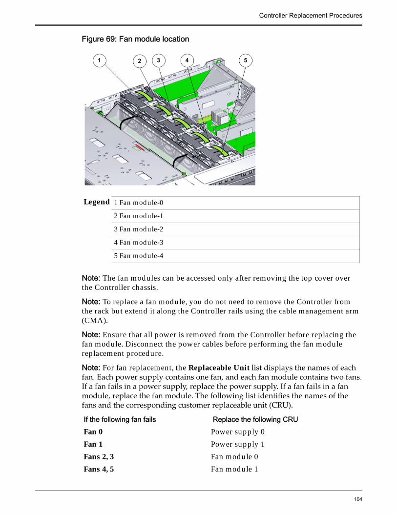
Figure 69: Fan module location
Legend 1 Fan module-0
2 Fan module-1
3 Fan module-2
4 Fan module-3
5 Fan module-4
Note: The fan modules can be accessed only after removing the top cover overthe Controller chassis.
Note: To replace a fan module, you do not need to remove the Controller fromthe rack but extend it along the Controller rails using the cable management arm(CMA).
Note: Ensure that all power is removed from the Controller before replacing thefan module. Disconnect the power cables before performing the fan modulereplacement procedure.
Note: For fan replacement, the Replaceable Unit list displays the names of eachfan. Each power supply contains one fan, and each fan module contains two fans.If a fan fails in a power supply, replace the power supply. If a fan fails in a fanmodule, replace the fan module. The following list identifies the names of thefans and the corresponding customer replaceable unit (CRU).
If the following fan fails Replace the following CRUFan 0 Power supply 0Fan 1 Power supply 1Fans 2, 3 Fan module 0Fans 4, 5 Fan module 1
Controller Replacement Procedures
104
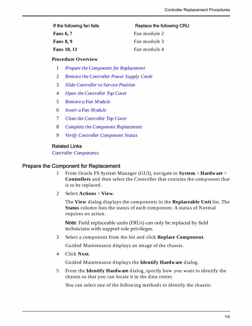
If the following fan fails Replace the following CRUFans 6, 7 Fan module 2Fans 8, 9 Fan module 3Fans 10, 11 Fan module 4
Procedure Overview
1 Prepare the Component for Replacement
2 Remove the Controller Power Supply Cords
3 Slide Controller to Service Position
4 Open the Controller Top Cover
5 Remove a Fan Module
6 Insert a Fan Module
7 Close the Controller Top Cover
8 Complete the Component Replacement
9 Verify Controller Component Status
Related LinksController Components
Prepare the Component for Replacement1 From Oracle FS System Manager (GUI), navigate to System > Hardware >
Controllers and then select the Controller that contains the component thatis to be replaced.
2 Select Actions > View.
The View dialog displays the components in the Replaceable Unit list. TheStatus column lists the status of each component. A status of Normalrequires no action.
Note: Field replaceable units (FRUs) can only be replaced by fieldtechnicians with support role privileges.
3 Select a component from the list and click Replace Component.
Guided Maintenance displays an image of the chassis.
4 Click Next.
Guided Maintenance displays the Identify Hardware dialog.
5 From the Identify Hardware dialog, specify how you want to identify thechassis so that you can locate it in the data center.
You can select one of the following methods to identify the chassis:
Controller Replacement Procedures
105
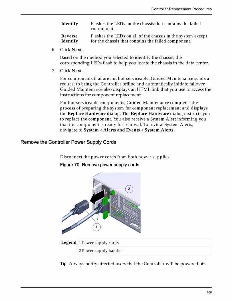
Identify Flashes the LEDs on the chassis that contains the failedcomponent.
ReverseIdentify
Flashes the LEDs on all of the chassis in the system exceptfor the chassis that contains the failed component.
6 Click Next.
Based on the method you selected to identify the chassis, thecorresponding LEDs flash to help you locate the chassis in the data center.
7 Click Next.
For components that are not hot-serviceable, Guided Maintenance sends arequest to bring the Controller offline and automatically initiate failover.Guided Maintenance also displays an HTML link that you use to access theinstructions for component replacement.
For hot-serviceable components, Guided Maintenance completes theprocess of preparing the system for component replacement and displaysthe Replace Hardware dialog. The Replace Hardware dialog instructs youto replace the component. You also receive a System Alert informing youthat the component is ready for removal. To review System Alerts,navigate to System > Alerts and Events > System Alerts.
Remove the Controller Power Supply Cords
Disconnect the power cords from both power supplies.
Figure 70: Remove power supply cords
Legend 1 Power supply cords
2 Power supply handle
Tip: Always notify affected users that the Controller will be powered off.
Controller Replacement Procedures
106
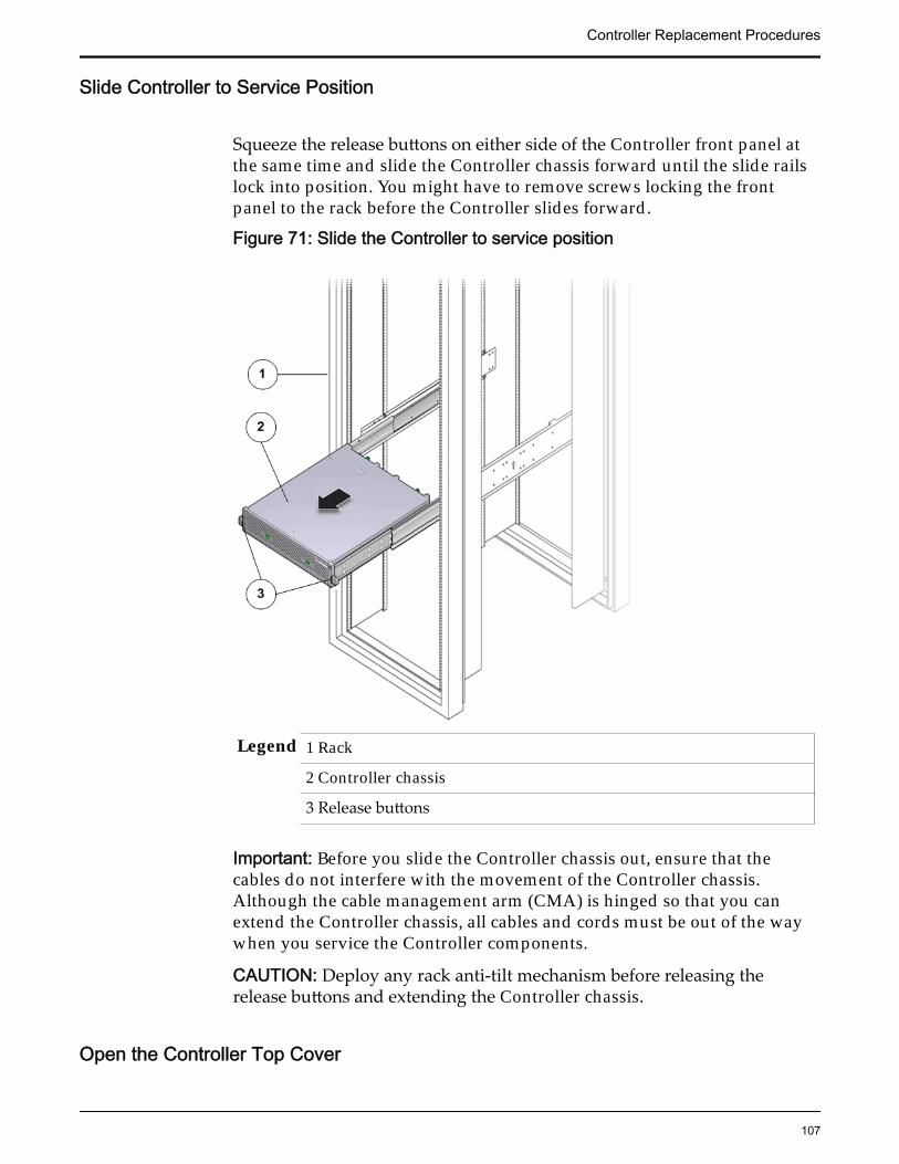
Slide Controller to Service Position
Squeeze the release buttons on either side of the Controller front panel atthe same time and slide the Controller chassis forward until the slide railslock into position. You might have to remove screws locking the frontpanel to the rack before the Controller slides forward.
Figure 71: Slide the Controller to service position
Legend 1 Rack
2 Controller chassis
3 Release buttons
Important: Before you slide the Controller chassis out, ensure that thecables do not interfere with the movement of the Controller chassis.Although the cable management arm (CMA) is hinged so that you canextend the Controller chassis, all cables and cords must be out of the waywhen you service the Controller components.
CAUTION: Deploy any rack anti-tilt mechanism before releasing therelease buttons and extending the Controller chassis.
Open the Controller Top Cover
Controller Replacement Procedures
107
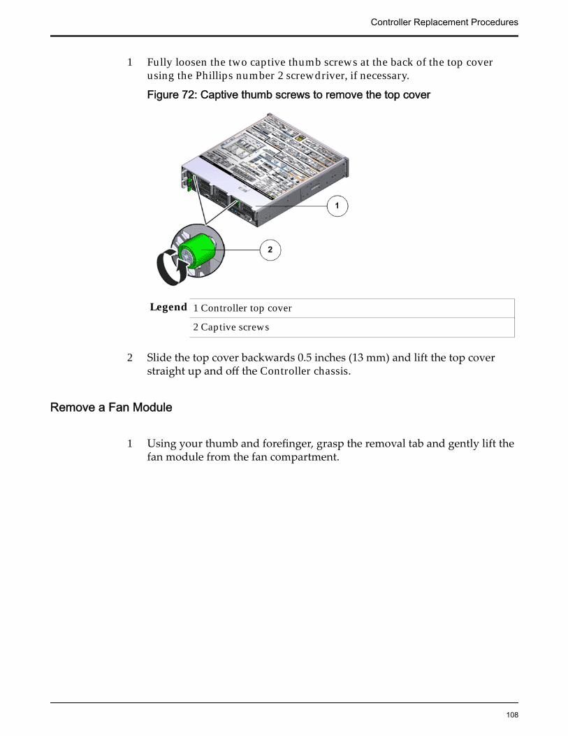
1 Fully loosen the two captive thumb screws at the back of the top coverusing the Phillips number 2 screwdriver, if necessary.
Figure 72: Captive thumb screws to remove the top cover
Legend 1 Controller top cover
2 Captive screws
2 Slide the top cover backwards 0.5 inches (13 mm) and lift the top coverstraight up and off the Controller chassis.
Remove a Fan Module
1 Using your thumb and forefinger, grasp the removal tab and gently lift thefan module from the fan compartment.
Controller Replacement Procedures
108
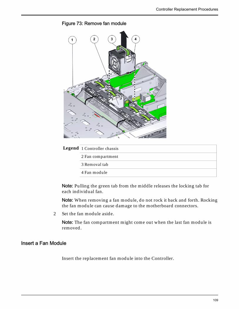
Figure 73: Remove fan module
Legend 1 Controller chassis
2 Fan compartment
3 Removal tab
4 Fan module
Note: Pulling the green tab from the middle releases the locking tab foreach individual fan.
Note: When removing a fan module, do not rock it back and forth. Rockingthe fan module can cause damage to the motherboard connectors.
2 Set the fan module aside.
Note: The fan compartment might come out when the last fan module isremoved.
Insert a Fan Module
Insert the replacement fan module into the Controller.
Controller Replacement Procedures
109
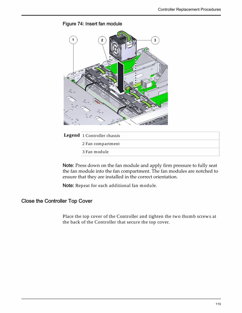
Figure 74: Insert fan module
Legend 1 Controller chassis
2 Fan compartment
3 Fan module
Note: Press down on the fan module and apply firm pressure to fully seatthe fan module into the fan compartment. The fan modules are notched toensure that they are installed in the correct orientation.
Note: Repeat for each additional fan module.
Close the Controller Top Cover
Place the top cover of the Controller and tighten the two thumb screws atthe back of the Controller that secure the top cover.
Controller Replacement Procedures
110

Figure 75: Close Controller top cover
Legend 1 Thumb screws
2 Controller top cover
3 Controller
Complete the Component Replacement
1 Slide the Controller back into rack position.
2 Connect the AC power cords to power on the Controller.
Note: The Controller automatically powers up when the power cords areplugged in.
Verify Controller Component Status
1 From Guided Maintenance, verify that the status is Normal.
You can also verify the status by navigating to System > Hardware andthen selecting a chassis. The Overview page for the selected chassis lists thestatus of each component.
Note: The Controller status will be visible several minutes after beingpowered on.
2 Review the status of the LEDs to confirm a status of Normal.
Controller Replacement Procedures
111
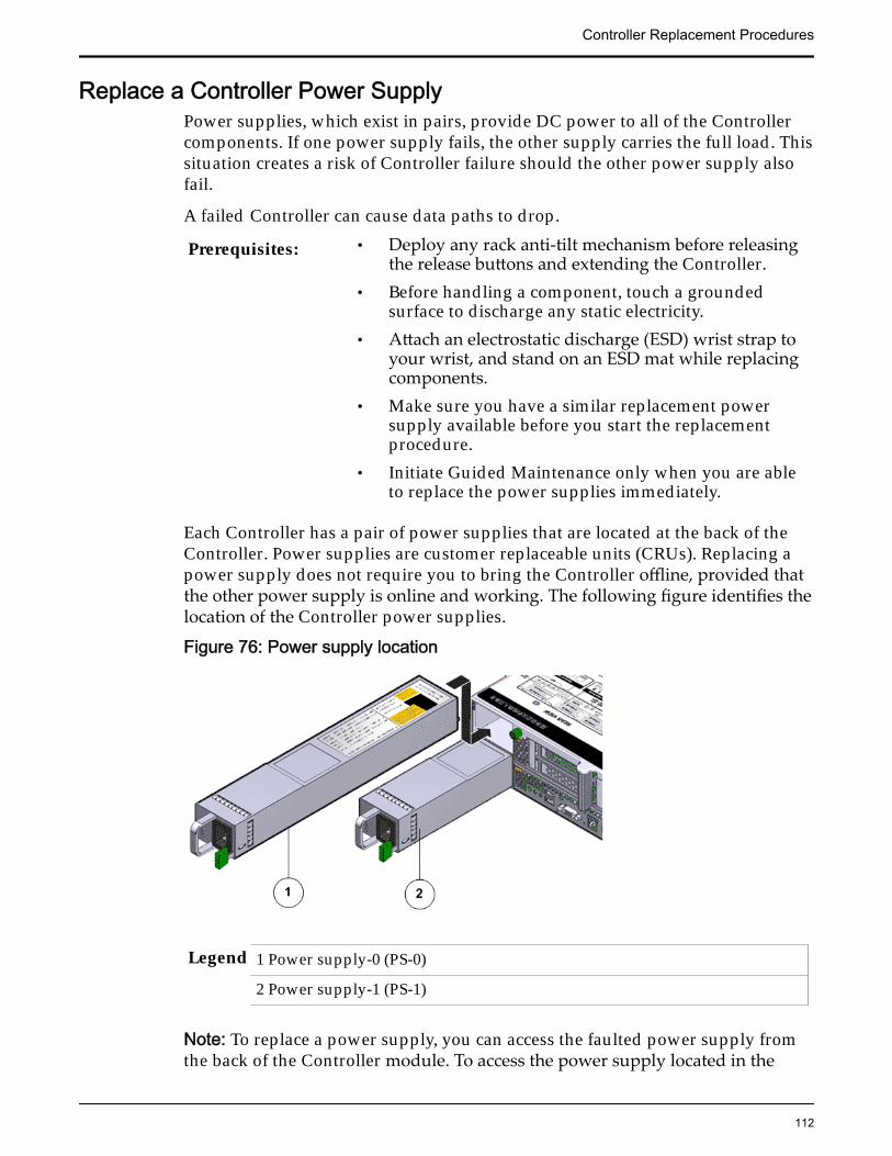
Replace a Controller Power SupplyPower supplies, which exist in pairs, provide DC power to all of the Controllercomponents. If one power supply fails, the other supply carries the full load. Thissituation creates a risk of Controller failure should the other power supply alsofail.
A failed Controller can cause data paths to drop.
Prerequisites: • Deploy any rack anti-tilt mechanism before releasingthe release buttons and extending the Controller.
• Before handling a component, touch a groundedsurface to discharge any static electricity.
• Attach an electrostatic discharge (ESD) wrist strap toyour wrist, and stand on an ESD mat while replacingcomponents.
• Make sure you have a similar replacement powersupply available before you start the replacementprocedure.
• Initiate Guided Maintenance only when you are ableto replace the power supplies immediately.
Each Controller has a pair of power supplies that are located at the back of theController. Power supplies are customer replaceable units (CRUs). Replacing apower supply does not require you to bring the Controller offline, provided thatthe other power supply is online and working. The following figure identifies thelocation of the Controller power supplies.
Figure 76: Power supply location
Legend 1 Power supply-0 (PS-0)
2 Power supply-1 (PS-1)
Note: To replace a power supply, you can access the faulted power supply fromthe back of the Controller module. To access the power supply located in the
Controller Replacement Procedures
112
bottom slot (PS-1), the CMA clip must be disconnected to enable the powersupply to clear the support arm.
Note: Replacing the power supply does not require you to slide the Controllerinto the extended rack position and can be performed while the Controller is inthe rack position.
Note: Ensure that the power strain relief strap on the power supply is positionedcorrectly such that there is proper clearance and the power supplies can be re-inserted into the power supply compartment without interference.
Note: Ensure that the power cable is routed correctly and there is no interferencewith the Controller chassis.
Important: Do not remove the failed power supply until you have a replacementpower supply to ensure proper airflow in the Controller.
Note: For fan replacement, the Replaceable Unit list displays the names of eachfan. Each power supply contains one fan, and each fan module contains two fans.If a fan fails in a power supply, replace the power supply. If a fan fails in a fanmodule, replace the fan module. The following list identifies the names of thefans and the corresponding customer replaceable unit (CRU).
If the following fan fails Replace the following CRUFan 0 Power supply 0Fan 1 Power supply 1Fans 2, 3 Fan module 0Fans 4, 5 Fan module 1Fans 6, 7 Fan module 2Fans 8, 9 Fan module 3Fans 10, 11 Fan module 4
Procedure Overview
1 Prepare the Component for Replacement
2 Remove the Power Cord
3 Remove a Power Supply
4 Insert a Power Supply
5 Insert the Power Cord
6 Verify Controller Component Status
Related LinksController Components
Controller Replacement Procedures
113
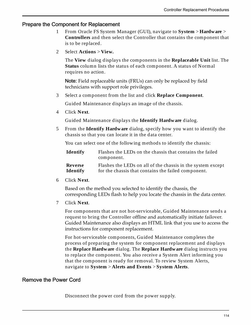
Prepare the Component for Replacement1 From Oracle FS System Manager (GUI), navigate to System > Hardware >
Controllers and then select the Controller that contains the component thatis to be replaced.
2 Select Actions > View.
The View dialog displays the components in the Replaceable Unit list. TheStatus column lists the status of each component. A status of Normalrequires no action.
Note: Field replaceable units (FRUs) can only be replaced by fieldtechnicians with support role privileges.
3 Select a component from the list and click Replace Component.
Guided Maintenance displays an image of the chassis.
4 Click Next.
Guided Maintenance displays the Identify Hardware dialog.
5 From the Identify Hardware dialog, specify how you want to identify thechassis so that you can locate it in the data center.
You can select one of the following methods to identify the chassis:
Identify Flashes the LEDs on the chassis that contains the failedcomponent.
ReverseIdentify
Flashes the LEDs on all of the chassis in the system exceptfor the chassis that contains the failed component.
6 Click Next.
Based on the method you selected to identify the chassis, thecorresponding LEDs flash to help you locate the chassis in the data center.
7 Click Next.
For components that are not hot-serviceable, Guided Maintenance sends arequest to bring the Controller offline and automatically initiate failover.Guided Maintenance also displays an HTML link that you use to access theinstructions for component replacement.
For hot-serviceable components, Guided Maintenance completes theprocess of preparing the system for component replacement and displaysthe Replace Hardware dialog. The Replace Hardware dialog instructs youto replace the component. You also receive a System Alert informing youthat the component is ready for removal. To review System Alerts,navigate to System > Alerts and Events > System Alerts.
Remove the Power Cord
Disconnect the power cord from the power supply.
Controller Replacement Procedures
114
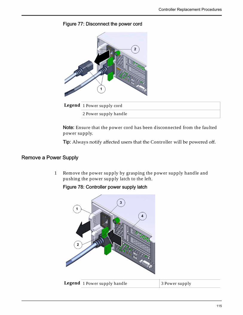
Figure 77: Disconnect the power cord
Legend 1 Power supply cord
2 Power supply handle
Note: Ensure that the power cord has been disconnected from the faultedpower supply.
Tip: Always notify affected users that the Controller will be powered off.
Remove a Power Supply
1 Remove the power supply by grasping the power supply handle andpushing the power supply latch to the left.
Figure 78: Controller power supply latch
Legend 1 Power supply handle 3 Power supply
Controller Replacement Procedures
115
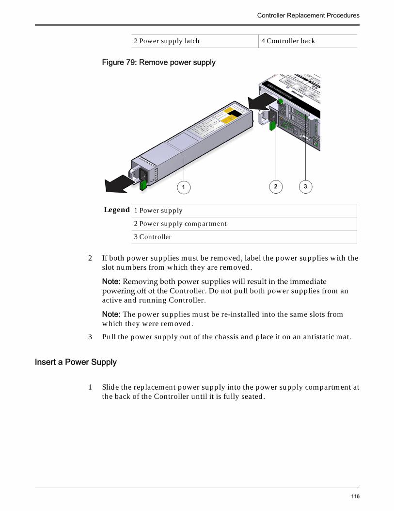
2 Power supply latch 4 Controller back
Figure 79: Remove power supply
Legend 1 Power supply
2 Power supply compartment
3 Controller
2 If both power supplies must be removed, label the power supplies with theslot numbers from which they are removed.
Note: Removing both power supplies will result in the immediatepowering off of the Controller. Do not pull both power supplies from anactive and running Controller.
Note: The power supplies must be re-installed into the same slots fromwhich they were removed.
3 Pull the power supply out of the chassis and place it on an antistatic mat.
Insert a Power Supply
1 Slide the replacement power supply into the power supply compartment atthe back of the Controller until it is fully seated.
Controller Replacement Procedures
116
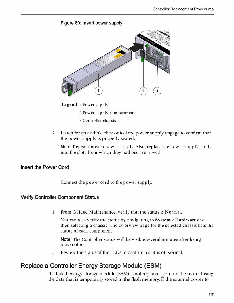
Figure 80: Insert power supply
Legend 1 Power supply
2 Power supply compartment
3 Controller chassis
2 Listen for an audible click or feel the power supply engage to confirm thatthe power supply is properly seated.
Note: Repeat for each power supply. Also, replace the power supplies onlyinto the slots from which they had been removed.
Insert the Power Cord
Connect the power cord to the power supply.
Verify Controller Component Status
1 From Guided Maintenance, verify that the status is Normal.
You can also verify the status by navigating to System > Hardware andthen selecting a chassis. The Overview page for the selected chassis lists thestatus of each component.
Note: The Controller status will be visible several minutes after beingpowered on.
2 Review the status of the LEDs to confirm a status of Normal.
Replace a Controller Energy Storage Module (ESM)If a failed energy storage module (ESM) is not replaced, you run the risk of losingthe data that is temporarily stored in the flash memory. If the external power to
Controller Replacement Procedures
117
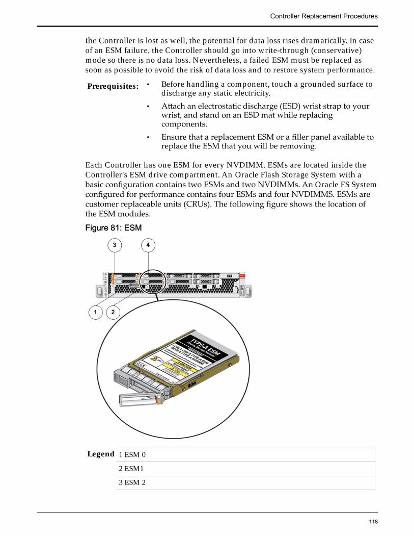
the Controller is lost as well, the potential for data loss rises dramatically. In caseof an ESM failure, the Controller should go into write-through (conservative)mode so there is no data loss. Nevertheless, a failed ESM must be replaced assoon as possible to avoid the risk of data loss and to restore system performance.
Prerequisites: • Before handling a component, touch a grounded surface todischarge any static electricity.
• Attach an electrostatic discharge (ESD) wrist strap to yourwrist, and stand on an ESD mat while replacingcomponents.
• Ensure that a replacement ESM or a filler panel available toreplace the ESM that you will be removing.
Each Controller has one ESM for every NVDIMM. ESMs are located inside theController's ESM drive compartment. An Oracle Flash Storage System with abasic configuration contains two ESMs and two NVDIMMs. An Oracle FS Systemconfigured for performance contains four ESMs and four NVDIMMS. ESMs arecustomer replaceable units (CRUs). The following figure shows the location ofthe ESM modules.
Figure 81: ESM
Legend 1 ESM 0
2 ESM1
3 ESM 2
Controller Replacement Procedures
118
4 ESM 3
Important: Do not mix ESM and NVDIMM types. ESM type must match theNVDIMM type. For example, an ESM labeled A (ESM-A) must be paired with anNVDIMM labeled A (NVDIMM-A); The NVDIMM type is printed on a smalllabel near the end of the NVDIMM cable.
Note: To replace an ESM, you do not need to remove the Controller from the rackor even extend it along the Controller rails.
Note: Make a note of the ESM slot where the failed ESM was located so that thereplacement ESM can be placed in the same slot to avoid the risk of mis-configuration. Alternatively, replace the ESMs only one at a time, so that there isonly one empty ESM slot at any point in time.
Procedure Overview
1 Prepare the Component for Replacement
2 Remove an Air Filter
3 Remove a Controller Energy Storage Module (ESM)
4 Insert an Energy Storage Module
5 Insert an Air Filter
6 Verify Controller Component Status
Related LinksController Components
Prepare the Component for Replacement1 From Oracle FS System Manager (GUI), navigate to System > Hardware >
Controllers and then select the Controller that contains the component thatis to be replaced.
2 Select Actions > View.
The View dialog displays the components in the Replaceable Unit list. TheStatus column lists the status of each component. A status of Normalrequires no action.
Note: Field replaceable units (FRUs) can only be replaced by fieldtechnicians with support role privileges.
3 Select a component from the list and click Replace Component.
Guided Maintenance displays an image of the chassis.4 Click Next.
Guided Maintenance displays the Identify Hardware dialog.5 From the Identify Hardware dialog, specify how you want to identify the
chassis so that you can locate it in the data center.
Controller Replacement Procedures
119
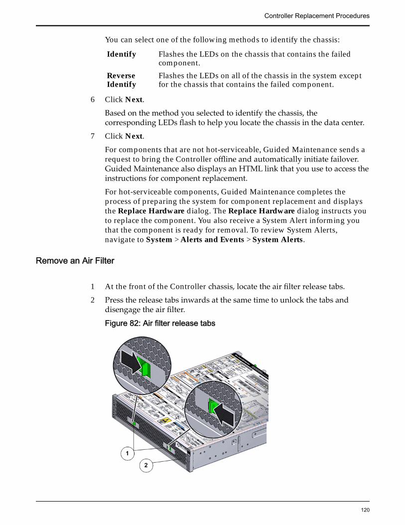
You can select one of the following methods to identify the chassis:
Identify Flashes the LEDs on the chassis that contains the failedcomponent.
ReverseIdentify
Flashes the LEDs on all of the chassis in the system exceptfor the chassis that contains the failed component.
6 Click Next.
Based on the method you selected to identify the chassis, thecorresponding LEDs flash to help you locate the chassis in the data center.
7 Click Next.
For components that are not hot-serviceable, Guided Maintenance sends arequest to bring the Controller offline and automatically initiate failover.Guided Maintenance also displays an HTML link that you use to access theinstructions for component replacement.
For hot-serviceable components, Guided Maintenance completes theprocess of preparing the system for component replacement and displaysthe Replace Hardware dialog. The Replace Hardware dialog instructs youto replace the component. You also receive a System Alert informing youthat the component is ready for removal. To review System Alerts,navigate to System > Alerts and Events > System Alerts.
Remove an Air Filter
1 At the front of the Controller chassis, locate the air filter release tabs.
2 Press the release tabs inwards at the same time to unlock the tabs anddisengage the air filter.
Figure 82: Air filter release tabs
Controller Replacement Procedures
120
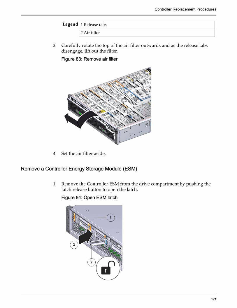
Legend 1 Release tabs
2 Air filter
3 Carefully rotate the top of the air filter outwards and as the release tabsdisengage, lift out the filter.
Figure 83: Remove air filter
4 Set the air filter aside.
Remove a Controller Energy Storage Module (ESM)
1 Remove the Controller ESM from the drive compartment by pushing thelatch release button to open the latch.
Figure 84: Open ESM latch
Controller Replacement Procedures
121
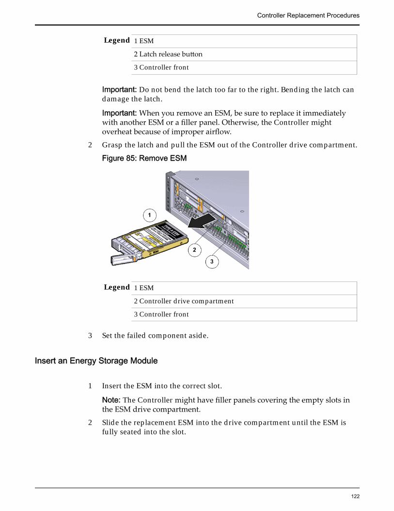
Legend 1 ESM
2 Latch release button
3 Controller front
Important: Do not bend the latch too far to the right. Bending the latch candamage the latch.
Important: When you remove an ESM, be sure to replace it immediatelywith another ESM or a filler panel. Otherwise, the Controller mightoverheat because of improper airflow.
2 Grasp the latch and pull the ESM out of the Controller drive compartment.
Figure 85: Remove ESM
Legend 1 ESM
2 Controller drive compartment
3 Controller front
3 Set the failed component aside.
Insert an Energy Storage Module
1 Insert the ESM into the correct slot.
Note: The Controller might have filler panels covering the empty slots inthe ESM drive compartment.
2 Slide the replacement ESM into the drive compartment until the ESM isfully seated into the slot.
Controller Replacement Procedures
122
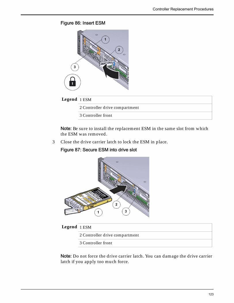
Figure 86: Insert ESM
Legend 1 ESM
2 Controller drive compartment
3 Controller front
Note: Be sure to install the replacement ESM in the same slot from whichthe ESM was removed.
3 Close the drive carrier latch to lock the ESM in place.
Figure 87: Secure ESM into drive slot
Legend 1 ESM
2 Controller drive compartment
3 Controller front
Note: Do not force the drive carrier latch. You can damage the drive carrierlatch if you apply too much force.
Controller Replacement Procedures
123
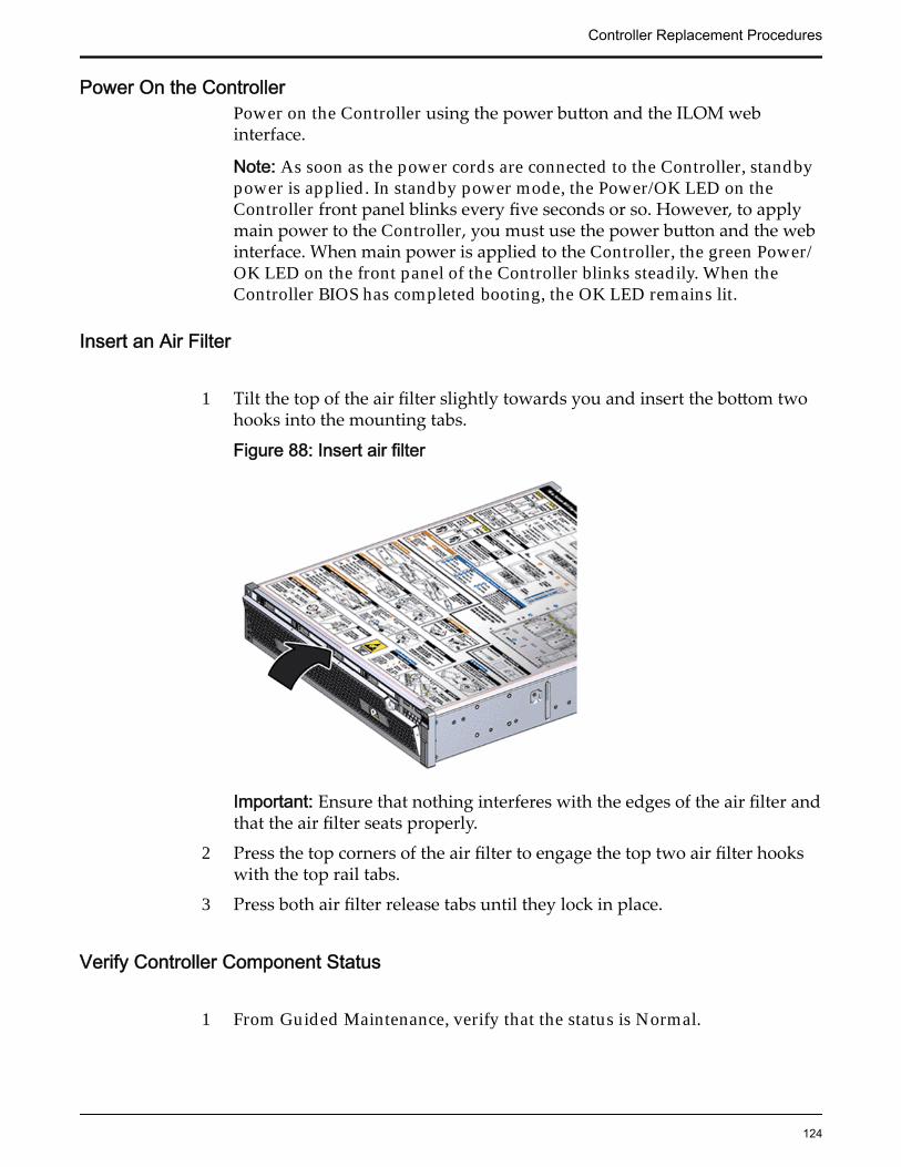
Power On the ControllerPower on the Controller using the power button and the ILOM webinterface.
Note: As soon as the power cords are connected to the Controller, standbypower is applied. In standby power mode, the Power/OK LED on theController front panel blinks every five seconds or so. However, to applymain power to the Controller, you must use the power button and the webinterface. When main power is applied to the Controller, the green Power/OK LED on the front panel of the Controller blinks steadily. When theController BIOS has completed booting, the OK LED remains lit.
Insert an Air Filter
1 Tilt the top of the air filter slightly towards you and insert the bottom twohooks into the mounting tabs.
Figure 88: Insert air filter
Important: Ensure that nothing interferes with the edges of the air filter andthat the air filter seats properly.
2 Press the top corners of the air filter to engage the top two air filter hookswith the top rail tabs.
3 Press both air filter release tabs until they lock in place.
Verify Controller Component Status
1 From Guided Maintenance, verify that the status is Normal.
Controller Replacement Procedures
124
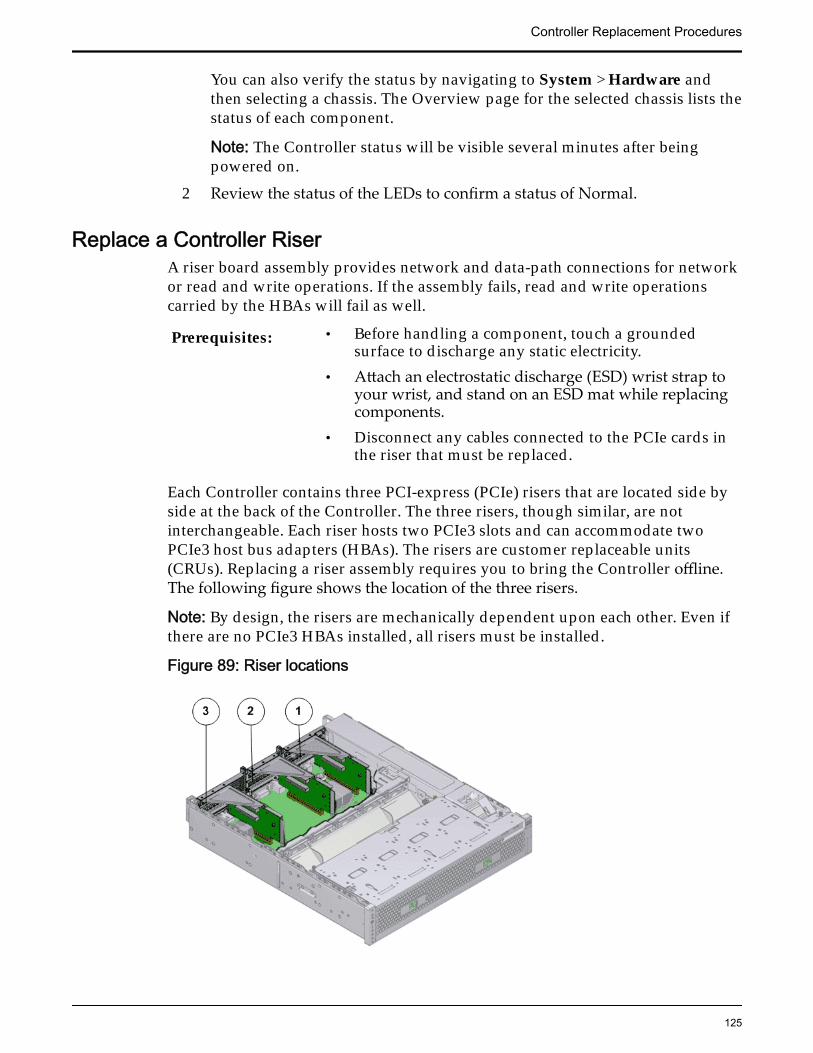
You can also verify the status by navigating to System > Hardware andthen selecting a chassis. The Overview page for the selected chassis lists thestatus of each component.
Note: The Controller status will be visible several minutes after beingpowered on.
2 Review the status of the LEDs to confirm a status of Normal.
Replace a Controller RiserA riser board assembly provides network and data-path connections for networkor read and write operations. If the assembly fails, read and write operationscarried by the HBAs will fail as well.
Prerequisites: • Before handling a component, touch a groundedsurface to discharge any static electricity.
• Attach an electrostatic discharge (ESD) wrist strap toyour wrist, and stand on an ESD mat while replacingcomponents.
• Disconnect any cables connected to the PCIe cards inthe riser that must be replaced.
Each Controller contains three PCI-express (PCIe) risers that are located side byside at the back of the Controller. The three risers, though similar, are notinterchangeable. Each riser hosts two PCIe3 slots and can accommodate twoPCIe3 host bus adapters (HBAs). The risers are customer replaceable units(CRUs). Replacing a riser assembly requires you to bring the Controller offline.The following figure shows the location of the three risers.
Note: By design, the risers are mechanically dependent upon each other. Even ifthere are no PCIe3 HBAs installed, all risers must be installed.
Figure 89: Riser locations
Controller Replacement Procedures
125
Legend 1 Riser 1
2 Riser 2
3 Riser 3 with latch
Note: The risers can be accessed only after removing the top cover over theController chassis.
Note: To replace a riser, you do not need to remove the Controller from the rackbut extend it along the Controller rails using the cable management arm (CMA).
Note: Ensure that all power is removed from the Controller before replacing theriser. Disconnect the power cords before performing the riser replacementprocedure.
Procedure Overview
1 Prepare the Component for Replacement
2 Remove the Controller Power Supply Cords
3 Slide Controller to Service Position
4 Disconnect Controller Cabling
5 Open the Controller Top Cover
6 Remove a Riser
7 Insert a Riser
8 Close the Controller Top Cover
9 Reconnect Controller Cabling
10 Complete the Component Replacement
11 Verify Controller Component Status
Related LinksController Components
Prepare the Component for Replacement
1 From Oracle FS System Manager (GUI), navigate to Support > SystemTrouble.
2 Select the Controller that contains the component that is to be replaced.
3 Select Actions > Replace Component.Guided Maintenance displays the list of replaceable components for theController.
Note: Field replaceable units (FRUs) can only be replaced by fieldtechnicians with support role privileges.
4 Select a component from the list.
Controller Replacement Procedures
126
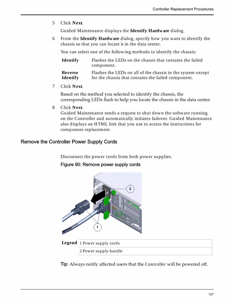
5 Click Next.
Guided Maintenance displays the Identify Hardware dialog.
6 From the Identify Hardware dialog, specify how you want to identify thechassis so that you can locate it in the data center.
You can select one of the following methods to identify the chassis:
Identify Flashes the LEDs on the chassis that contains the failedcomponent.
ReverseIdentify
Flashes the LEDs on all of the chassis in the system exceptfor the chassis that contains the failed component.
7 Click Next.
Based on the method you selected to identify the chassis, thecorresponding LEDs flash to help you locate the chassis in the data center.
8 Click Next.Guided Maintenance sends a request to shut down the software runningon the Controller and automatically initiates failover. Guided Maintenancealso displays an HTML link that you use to access the instructions forcomponent replacement.
Remove the Controller Power Supply Cords
Disconnect the power cords from both power supplies.
Figure 90: Remove power supply cords
Legend 1 Power supply cords
2 Power supply handle
Tip: Always notify affected users that the Controller will be powered off.
Controller Replacement Procedures
127
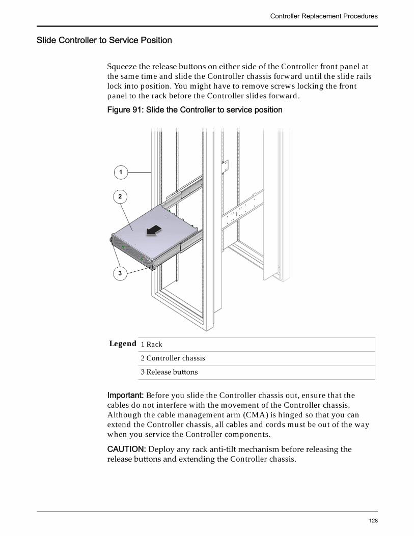
Slide Controller to Service Position
Squeeze the release buttons on either side of the Controller front panel atthe same time and slide the Controller chassis forward until the slide railslock into position. You might have to remove screws locking the frontpanel to the rack before the Controller slides forward.
Figure 91: Slide the Controller to service position
Legend 1 Rack
2 Controller chassis
3 Release buttons
Important: Before you slide the Controller chassis out, ensure that thecables do not interfere with the movement of the Controller chassis.Although the cable management arm (CMA) is hinged so that you canextend the Controller chassis, all cables and cords must be out of the waywhen you service the Controller components.
CAUTION: Deploy any rack anti-tilt mechanism before releasing therelease buttons and extending the Controller chassis.
Controller Replacement Procedures
128
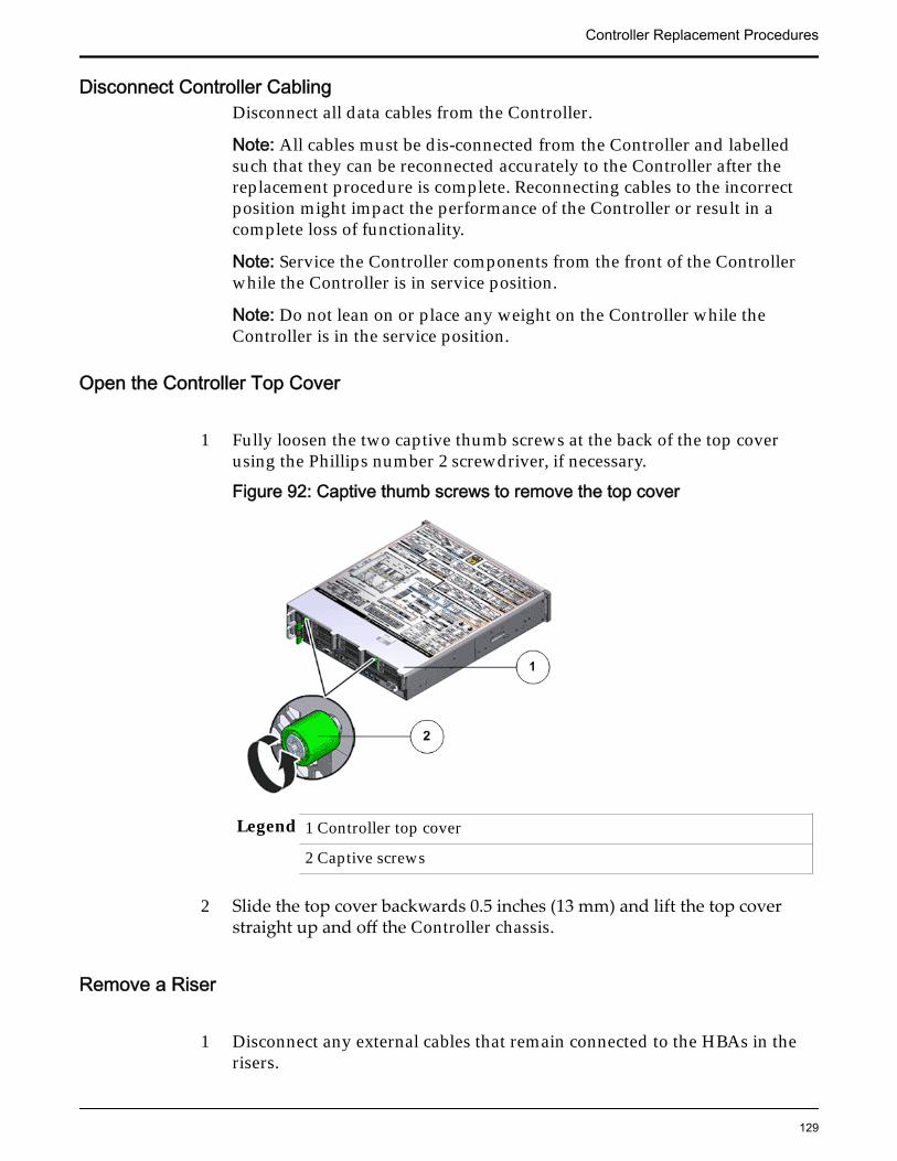
Disconnect Controller CablingDisconnect all data cables from the Controller.
Note: All cables must be dis-connected from the Controller and labelledsuch that they can be reconnected accurately to the Controller after thereplacement procedure is complete. Reconnecting cables to the incorrectposition might impact the performance of the Controller or result in acomplete loss of functionality.
Note: Service the Controller components from the front of the Controllerwhile the Controller is in service position.
Note: Do not lean on or place any weight on the Controller while theController is in the service position.
Open the Controller Top Cover
1 Fully loosen the two captive thumb screws at the back of the top coverusing the Phillips number 2 screwdriver, if necessary.
Figure 92: Captive thumb screws to remove the top cover
Legend 1 Controller top cover
2 Captive screws
2 Slide the top cover backwards 0.5 inches (13 mm) and lift the top coverstraight up and off the Controller chassis.
Remove a Riser
1 Disconnect any external cables that remain connected to the HBAs in therisers.
Controller Replacement Procedures
129
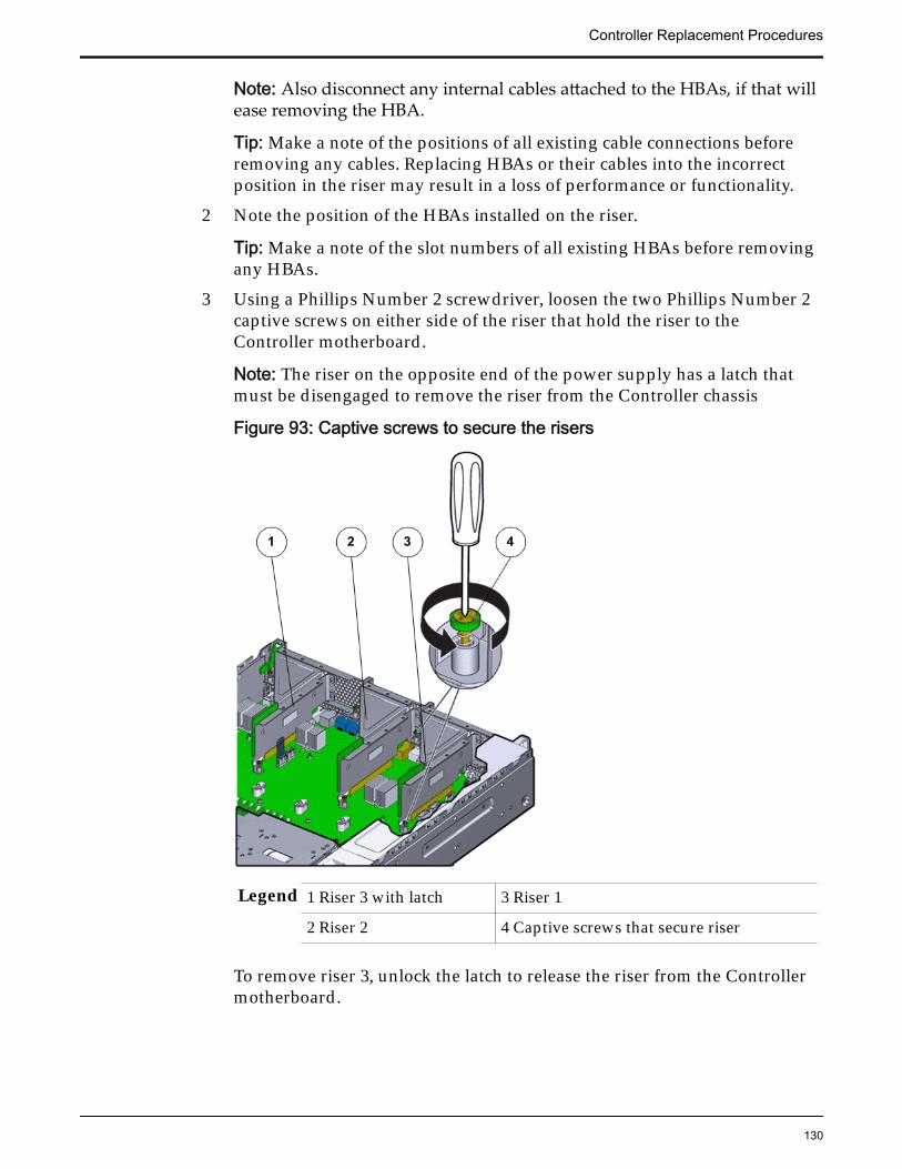
Note: Also disconnect any internal cables attached to the HBAs, if that willease removing the HBA.
Tip: Make a note of the positions of all existing cable connections beforeremoving any cables. Replacing HBAs or their cables into the incorrectposition in the riser may result in a loss of performance or functionality.
2 Note the position of the HBAs installed on the riser.
Tip: Make a note of the slot numbers of all existing HBAs before removingany HBAs.
3 Using a Phillips Number 2 screwdriver, loosen the two Phillips Number 2captive screws on either side of the riser that hold the riser to theController motherboard.
Note: The riser on the opposite end of the power supply has a latch thatmust be disengaged to remove the riser from the Controller chassis
Figure 93: Captive screws to secure the risers
Legend 1 Riser 3 with latch 3 Riser 1
2 Riser 2 4 Captive screws that secure riser
To remove riser 3, unlock the latch to release the riser from the Controllermotherboard.
Controller Replacement Procedures
130

Figure 94: Unlock Riser 3 latch
Legend 1 Riser 3 latch 3 HBA
2 Riser 3
4 Carefully pull the riser straight up and place it aside.
Figure 95: Remove riser
Legend 1 Riser
2 Controller motherboard
Controller Replacement Procedures
131
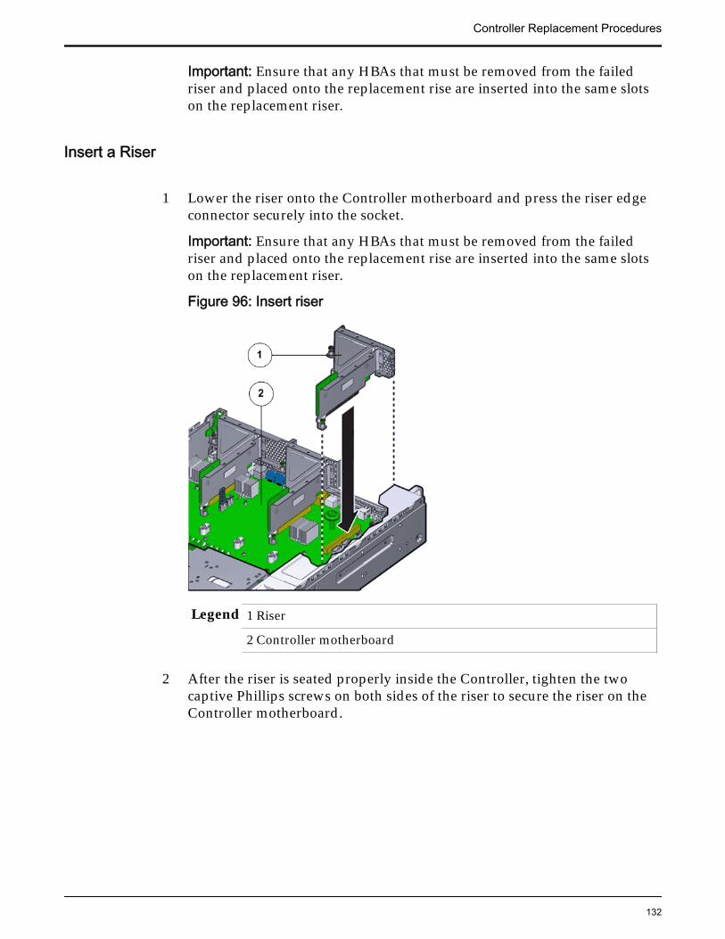
Important: Ensure that any HBAs that must be removed from the failedriser and placed onto the replacement rise are inserted into the same slotson the replacement riser.
Insert a Riser
1 Lower the riser onto the Controller motherboard and press the riser edgeconnector securely into the socket.
Important: Ensure that any HBAs that must be removed from the failedriser and placed onto the replacement rise are inserted into the same slotson the replacement riser.
Figure 96: Insert riser
Legend 1 Riser
2 Controller motherboard
2 After the riser is seated properly inside the Controller, tighten the twocaptive Phillips screws on both sides of the riser to secure the riser on theController motherboard.
Controller Replacement Procedures
132
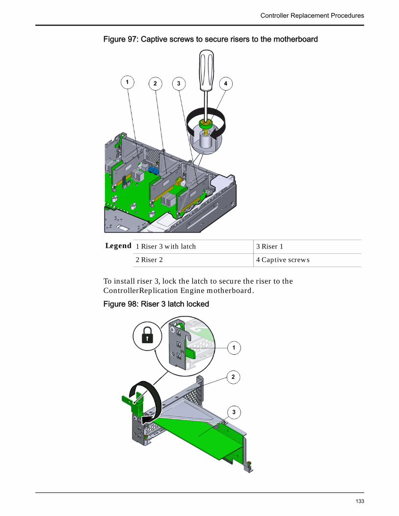
Figure 97: Captive screws to secure risers to the motherboard
Legend 1 Riser 3 with latch 3 Riser 1
2 Riser 2 4 Captive screws
To install riser 3, lock the latch to secure the riser to theControllerReplication Engine motherboard.
Figure 98: Riser 3 latch locked
Controller Replacement Procedures
133
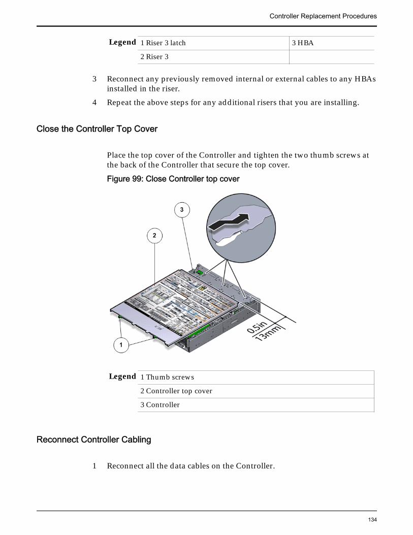
Legend 1 Riser 3 latch 3 HBA
2 Riser 3
3 Reconnect any previously removed internal or external cables to any HBAsinstalled in the riser.
4 Repeat the above steps for any additional risers that you are installing.
Close the Controller Top Cover
Place the top cover of the Controller and tighten the two thumb screws atthe back of the Controller that secure the top cover.
Figure 99: Close Controller top cover
Legend 1 Thumb screws
2 Controller top cover
3 Controller
Reconnect Controller Cabling
1 Reconnect all the data cables on the Controller.
Controller Replacement Procedures
134
Note: Oracle Customer Support recommends labeling all cables connectedto the Controller so that the cables can be reconnected accurately to theController after the replacement procedure is complete.
2 Reconnect the CMA to the Controller by attaching the release tab on theleft and right side of the CMA.
Complete the Component Replacement
1 Slide the Controller back into rack position.
2 Connect the AC power cords to power on the Controller.
Note: The Controller automatically powers up when the power cords areplugged in.
Verify Controller Component Status
1 From Guided Maintenance, verify that the status is Normal.
You can also verify the status by navigating to System > Hardware andthen selecting a chassis. The Overview page for the selected chassis lists thestatus of each component.
Note: The Controller status will be visible several minutes after beingpowered on.
2 Review the status of the LEDs to confirm a status of Normal.
Replace a Controller HBAAn HBA is a circuit board installed inside the Controller riser board assembly.
A failed HBA might cause a Controller failure that could result in the remainingControllers to shoulder the load. Therefore, if failed, an HBA must be replacedimmediately. Additional HBAs can also be added to existing configurations.
Prerequisites: • Ensure that you have a Phillips Number 2screwdriver with at least a 4-inch shaft.
• Before handling a component, touch a groundedsurface to discharge any static electricity.
• Attach an electrostatic discharge (ESD) wrist strap toyour wrist, and stand on an ESD mat while replacingcomponents.
• Keep filler panels available in case you only removethe HBA and do not plan to replace the HBAimmediately.
Controller Replacement Procedures
135
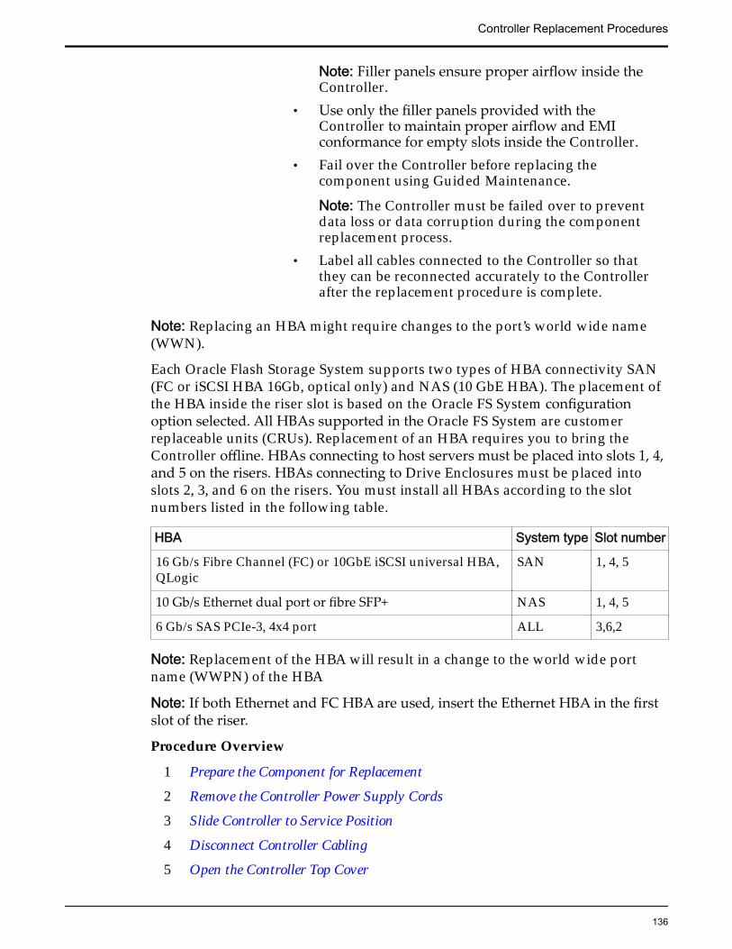
Note: Filler panels ensure proper airflow inside theController.
• Use only the filler panels provided with theController to maintain proper airflow and EMIconformance for empty slots inside the Controller.
• Fail over the Controller before replacing thecomponent using Guided Maintenance.
Note: The Controller must be failed over to preventdata loss or data corruption during the componentreplacement process.
• Label all cables connected to the Controller so thatthey can be reconnected accurately to the Controllerafter the replacement procedure is complete.
Note: Replacing an HBA might require changes to the port’s world wide name(WWN).
Each Oracle Flash Storage System supports two types of HBA connectivity SAN(FC or iSCSI HBA 16Gb, optical only) and NAS (10 GbE HBA). The placement ofthe HBA inside the riser slot is based on the Oracle FS System configurationoption selected. All HBAs supported in the Oracle FS System are customerreplaceable units (CRUs). Replacement of an HBA requires you to bring theController offline. HBAs connecting to host servers must be placed into slots 1, 4,and 5 on the risers. HBAs connecting to Drive Enclosures must be placed intoslots 2, 3, and 6 on the risers. You must install all HBAs according to the slotnumbers listed in the following table.
HBA System type Slot number
16 Gb/s Fibre Channel (FC) or 10GbE iSCSI universal HBA,QLogic
SAN 1, 4, 5
10 Gb/s Ethernet dual port or fibre SFP+ NAS 1, 4, 5
6 Gb/s SAS PCIe-3, 4x4 port ALL 3,6,2
Note: Replacement of the HBA will result in a change to the world wide portname (WWPN) of the HBA
Note: If both Ethernet and FC HBA are used, insert the Ethernet HBA in the firstslot of the riser.
Procedure Overview
1 Prepare the Component for Replacement
2 Remove the Controller Power Supply Cords
3 Slide Controller to Service Position
4 Disconnect Controller Cabling
5 Open the Controller Top Cover
Controller Replacement Procedures
136
6 Remove a Riser
7 Remove an HBA
8 Insert an HBA
9 Insert a Riser
10 Close the Controller Top Cover
11 Reconnect Controller Cabling
12 Complete the Component Replacement
13 Verify Controller Component Status
Related LinksController Components
Prepare the Component for Replacement1 From Oracle FS System Manager (GUI), navigate to System > Hardware >
Controllers and then select the Controller that contains the component thatis to be replaced.
2 Select Actions > View.
The View dialog displays the components in the Replaceable Unit list. TheStatus column lists the status of each component. A status of Normalrequires no action.
Note: Field replaceable units (FRUs) can only be replaced by fieldtechnicians with support role privileges.
3 Select a component from the list and click Replace Component.
Guided Maintenance displays an image of the chassis.4 Click Next.
Guided Maintenance displays the Identify Hardware dialog.5 From the Identify Hardware dialog, specify how you want to identify the
chassis so that you can locate it in the data center.
You can select one of the following methods to identify the chassis:
Identify Flashes the LEDs on the chassis that contains the failedcomponent.
ReverseIdentify
Flashes the LEDs on all of the chassis in the system exceptfor the chassis that contains the failed component.
6 Click Next.
Based on the method you selected to identify the chassis, thecorresponding LEDs flash to help you locate the chassis in the data center.
7 Click Next.
For components that are not hot-serviceable, Guided Maintenance sends arequest to bring the Controller offline and automatically initiate failover.
Controller Replacement Procedures
137
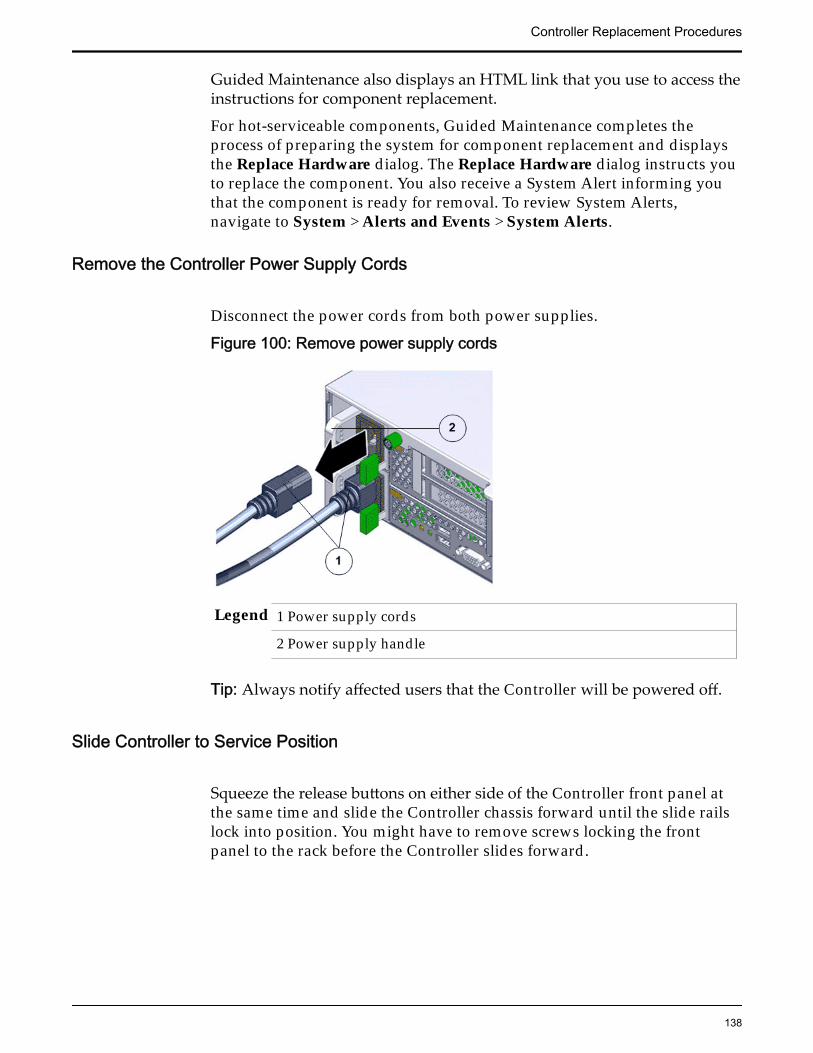
Guided Maintenance also displays an HTML link that you use to access theinstructions for component replacement.
For hot-serviceable components, Guided Maintenance completes theprocess of preparing the system for component replacement and displaysthe Replace Hardware dialog. The Replace Hardware dialog instructs youto replace the component. You also receive a System Alert informing youthat the component is ready for removal. To review System Alerts,navigate to System > Alerts and Events > System Alerts.
Remove the Controller Power Supply Cords
Disconnect the power cords from both power supplies.
Figure 100: Remove power supply cords
Legend 1 Power supply cords
2 Power supply handle
Tip: Always notify affected users that the Controller will be powered off.
Slide Controller to Service Position
Squeeze the release buttons on either side of the Controller front panel atthe same time and slide the Controller chassis forward until the slide railslock into position. You might have to remove screws locking the frontpanel to the rack before the Controller slides forward.
Controller Replacement Procedures
138
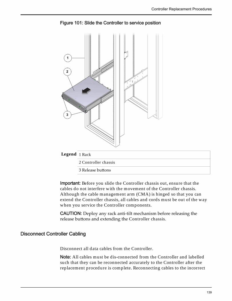
Figure 101: Slide the Controller to service position
Legend 1 Rack
2 Controller chassis
3 Release buttons
Important: Before you slide the Controller chassis out, ensure that thecables do not interfere with the movement of the Controller chassis.Although the cable management arm (CMA) is hinged so that you canextend the Controller chassis, all cables and cords must be out of the waywhen you service the Controller components.
CAUTION: Deploy any rack anti-tilt mechanism before releasing therelease buttons and extending the Controller chassis.
Disconnect Controller Cabling
Disconnect all data cables from the Controller.
Note: All cables must be dis-connected from the Controller and labelledsuch that they can be reconnected accurately to the Controller after thereplacement procedure is complete. Reconnecting cables to the incorrect
Controller Replacement Procedures
139
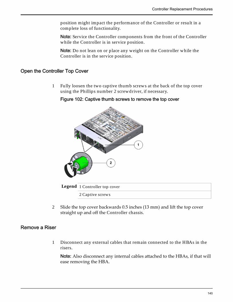
position might impact the performance of the Controller or result in acomplete loss of functionality.
Note: Service the Controller components from the front of the Controllerwhile the Controller is in service position.
Note: Do not lean on or place any weight on the Controller while theController is in the service position.
Open the Controller Top Cover
1 Fully loosen the two captive thumb screws at the back of the top coverusing the Phillips number 2 screwdriver, if necessary.
Figure 102: Captive thumb screws to remove the top cover
Legend 1 Controller top cover
2 Captive screws
2 Slide the top cover backwards 0.5 inches (13 mm) and lift the top coverstraight up and off the Controller chassis.
Remove a Riser
1 Disconnect any external cables that remain connected to the HBAs in therisers.
Note: Also disconnect any internal cables attached to the HBAs, if that willease removing the HBA.
Controller Replacement Procedures
140
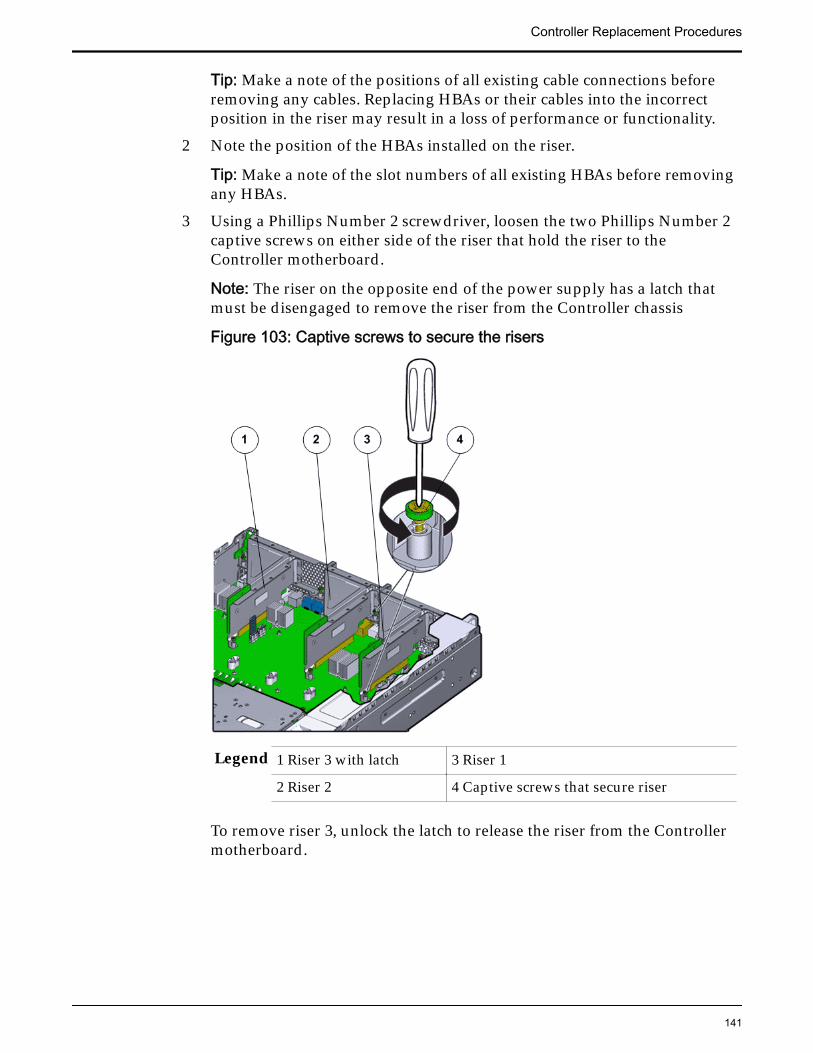
Tip: Make a note of the positions of all existing cable connections beforeremoving any cables. Replacing HBAs or their cables into the incorrectposition in the riser may result in a loss of performance or functionality.
2 Note the position of the HBAs installed on the riser.
Tip: Make a note of the slot numbers of all existing HBAs before removingany HBAs.
3 Using a Phillips Number 2 screwdriver, loosen the two Phillips Number 2captive screws on either side of the riser that hold the riser to theController motherboard.
Note: The riser on the opposite end of the power supply has a latch thatmust be disengaged to remove the riser from the Controller chassis
Figure 103: Captive screws to secure the risers
Legend 1 Riser 3 with latch 3 Riser 1
2 Riser 2 4 Captive screws that secure riser
To remove riser 3, unlock the latch to release the riser from the Controllermotherboard.
Controller Replacement Procedures
141
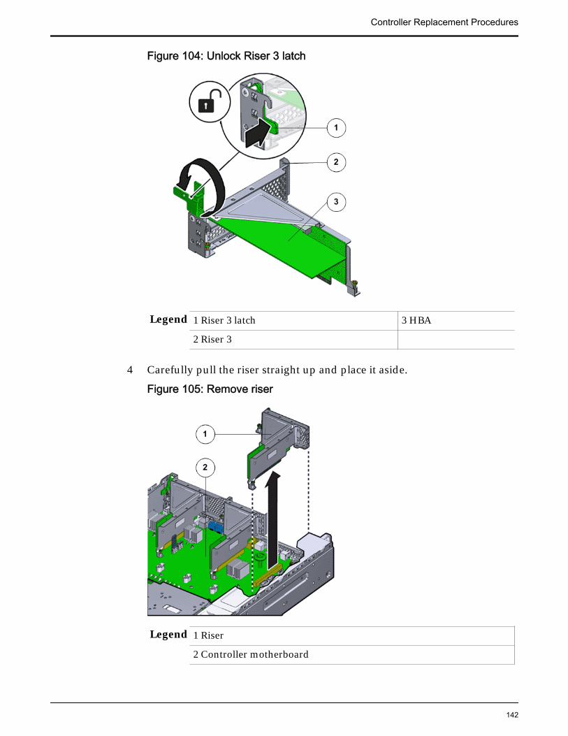
Figure 104: Unlock Riser 3 latch
Legend 1 Riser 3 latch 3 HBA
2 Riser 3
4 Carefully pull the riser straight up and place it aside.
Figure 105: Remove riser
Legend 1 Riser
2 Controller motherboard
Controller Replacement Procedures
142
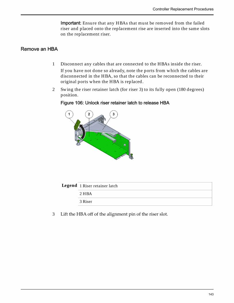
Important: Ensure that any HBAs that must be removed from the failedriser and placed onto the replacement rise are inserted into the same slotson the replacement riser.
Remove an HBA
1 Disconnect any cables that are connected to the HBAs inside the riser.If you have not done so already, note the ports from which the cables aredisconnected in the HBA, so that the cables can be reconnected to theiroriginal ports when the HBA is replaced.
2 Swing the riser retainer latch (for riser 3) to its fully open (180 degrees)position.
Figure 106: Unlock riser retainer latch to release HBA
Legend 1 Riser retainer latch
2 HBA
3 Riser
3 Lift the HBA off of the alignment pin of the riser slot.
Controller Replacement Procedures
143
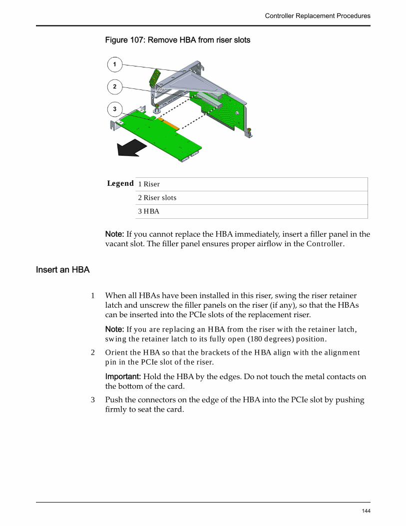
Figure 107: Remove HBA from riser slots
Legend 1 Riser
2 Riser slots
3 HBA
Note: If you cannot replace the HBA immediately, insert a filler panel in thevacant slot. The filler panel ensures proper airflow in the Controller.
Insert an HBA
1 When all HBAs have been installed in this riser, swing the riser retainerlatch and unscrew the filler panels on the riser (if any), so that the HBAscan be inserted into the PCIe slots of the replacement riser.
Note: If you are replacing an HBA from the riser with the retainer latch,swing the retainer latch to its fully open (180 degrees) position.
2 Orient the HBA so that the brackets of the HBA align with the alignmentpin in the PCIe slot of the riser.
Important: Hold the HBA by the edges. Do not touch the metal contacts onthe bottom of the card.
3 Push the connectors on the edge of the HBA into the PCIe slot by pushingfirmly to seat the card.
Controller Replacement Procedures
144
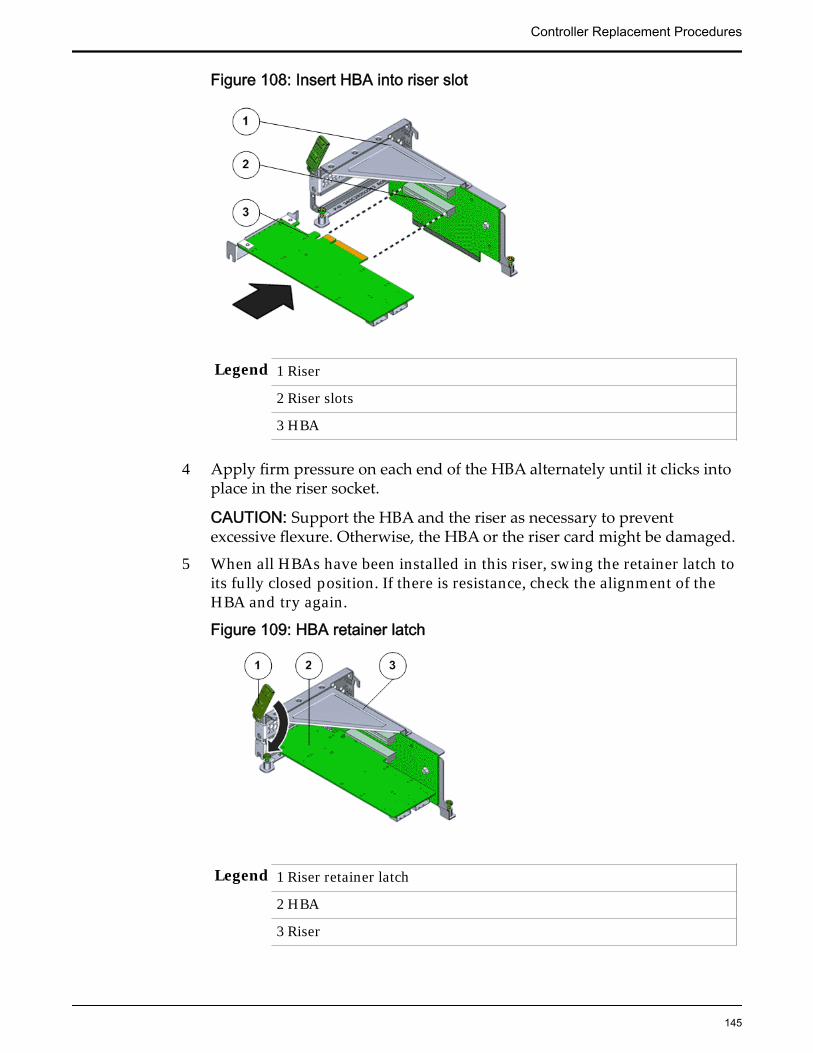
Figure 108: Insert HBA into riser slot
Legend 1 Riser
2 Riser slots
3 HBA
4 Apply firm pressure on each end of the HBA alternately until it clicks intoplace in the riser socket.
CAUTION: Support the HBA and the riser as necessary to preventexcessive flexure. Otherwise, the HBA or the riser card might be damaged.
5 When all HBAs have been installed in this riser, swing the retainer latch toits fully closed position. If there is resistance, check the alignment of theHBA and try again.
Figure 109: HBA retainer latch
Legend 1 Riser retainer latch
2 HBA
3 Riser
Controller Replacement Procedures
145
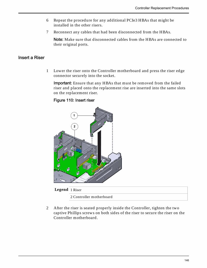
6 Repeat the procedure for any additional PCIe3 HBAs that might beinstalled in the other risers.
7 Reconnect any cables that had been disconnected from the HBAs.
Note: Make sure that disconnected cables from the HBAs are connected totheir original ports.
Insert a Riser
1 Lower the riser onto the Controller motherboard and press the riser edgeconnector securely into the socket.
Important: Ensure that any HBAs that must be removed from the failedriser and placed onto the replacement rise are inserted into the same slotson the replacement riser.
Figure 110: Insert riser
Legend 1 Riser
2 Controller motherboard
2 After the riser is seated properly inside the Controller, tighten the twocaptive Phillips screws on both sides of the riser to secure the riser on theController motherboard.
Controller Replacement Procedures
146

Figure 111: Captive screws to secure risers to the motherboard
Legend 1 Riser 3 with latch 3 Riser 1
2 Riser 2 4 Captive screws
To install riser 3, lock the latch to secure the riser to theControllerReplication Engine motherboard.
Figure 112: Riser 3 latch locked
Controller Replacement Procedures
147
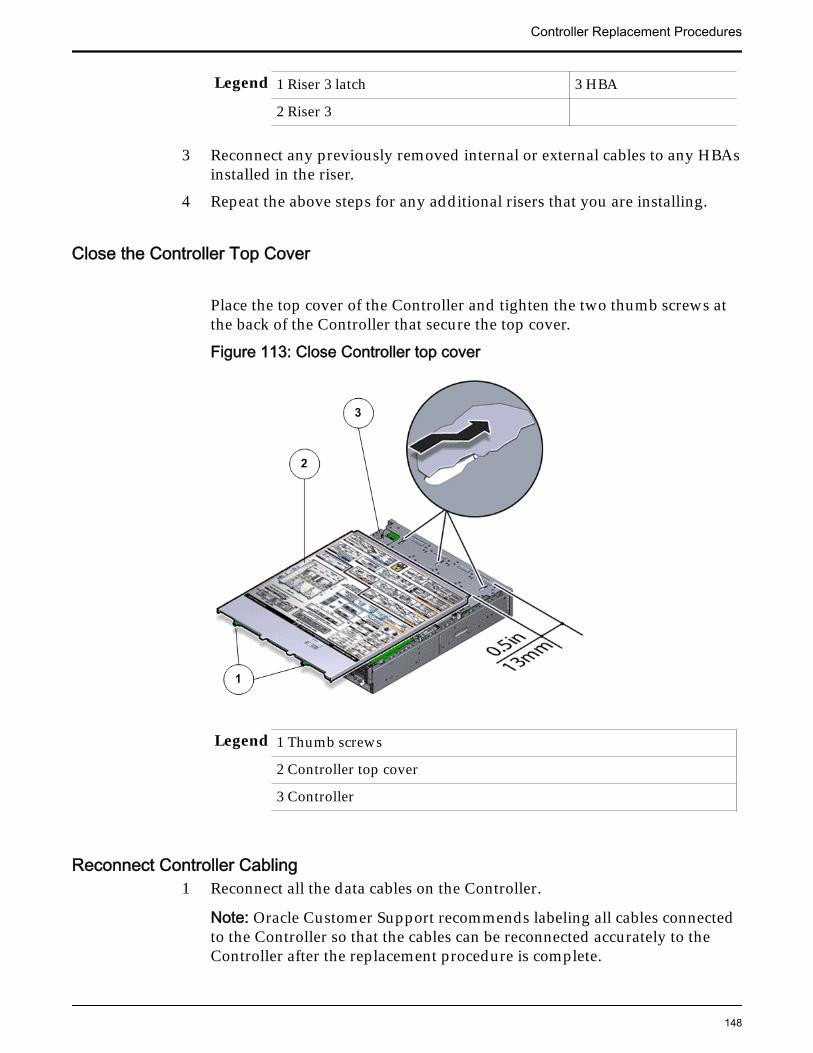
Legend 1 Riser 3 latch 3 HBA
2 Riser 3
3 Reconnect any previously removed internal or external cables to any HBAsinstalled in the riser.
4 Repeat the above steps for any additional risers that you are installing.
Close the Controller Top Cover
Place the top cover of the Controller and tighten the two thumb screws atthe back of the Controller that secure the top cover.
Figure 113: Close Controller top cover
Legend 1 Thumb screws
2 Controller top cover
3 Controller
Reconnect Controller Cabling1 Reconnect all the data cables on the Controller.
Note: Oracle Customer Support recommends labeling all cables connectedto the Controller so that the cables can be reconnected accurately to theController after the replacement procedure is complete.
Controller Replacement Procedures
148
2 Reconnect the CMA to the Controller by attaching the release tab on theleft and right side of the CMA.
Complete the Component Replacement
1 Slide the Controller back into rack position.
2 Connect the AC power cords to power on the Controller.
Note: The Controller automatically powers up when the power cords areplugged in.
Verify Controller Component Status
1 From Guided Maintenance, verify that the status is Normal.
You can also verify the status by navigating to System > Hardware andthen selecting a chassis. The Overview page for the selected chassis lists thestatus of each component.
Note: The Controller status will be visible several minutes after beingpowered on.
2 Review the status of the LEDs to confirm a status of Normal.
Replace a Controller DIMMDual in-line memory modules (DIMMs) provide random access memory (RAM)for the central processing units (CPUs) configured in the Controller. DIMMs areconnected to the DIMM slots located on both sides of the central processing unit(CPUs) and heat sinks on the Controller motherboard. A failed DIMM mightcause the Controller to be brought offline and must be replaced as soon aspossible.
Prerequisites: • Ensure that you have a Phillips Number 2screwdriver with at least a 4-inch shaft.
• Before handling a component, touch a groundedsurface to discharge any static electricity.
• Attach an electrostatic discharge (ESD) wrist strap toyour wrist, and stand on an ESD mat while replacingcomponents.
• Fail over the Controller before replacing thecomponent using Guided Maintenance.
Controller Replacement Procedures
149
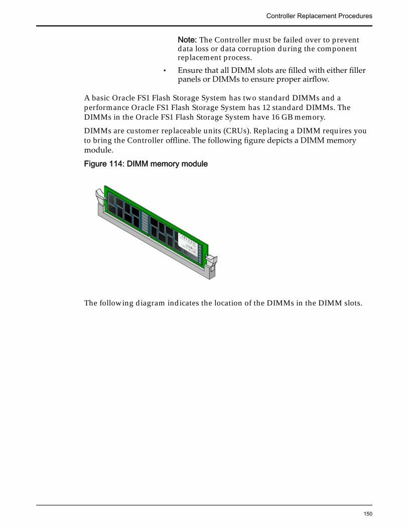
Note: The Controller must be failed over to preventdata loss or data corruption during the componentreplacement process.
• Ensure that all DIMM slots are filled with either fillerpanels or DIMMs to ensure proper airflow.
A basic Oracle FS1 Flash Storage System has two standard DIMMs and aperformance Oracle FS1 Flash Storage System has 12 standard DIMMs. TheDIMMs in the Oracle FS1 Flash Storage System have 16 GB memory.
DIMMs are customer replaceable units (CRUs). Replacing a DIMM requires youto bring the Controller offline. The following figure depicts a DIMM memorymodule.
Figure 114: DIMM memory module
The following diagram indicates the location of the DIMMs in the DIMM slots.
Controller Replacement Procedures
150
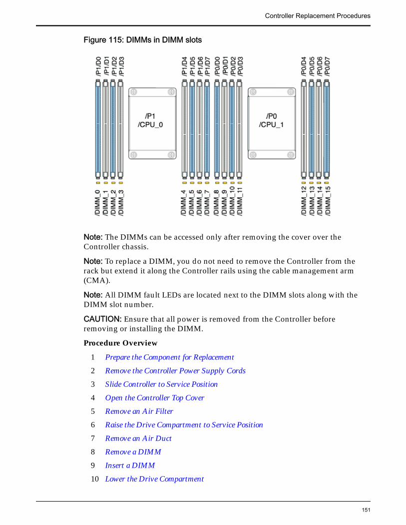
Figure 115: DIMMs in DIMM slots
Note: The DIMMs can be accessed only after removing the cover over theController chassis.
Note: To replace a DIMM, you do not need to remove the Controller from therack but extend it along the Controller rails using the cable management arm(CMA).
Note: All DIMM fault LEDs are located next to the DIMM slots along with theDIMM slot number.
CAUTION: Ensure that all power is removed from the Controller beforeremoving or installing the DIMM.
Procedure Overview
1 Prepare the Component for Replacement
2 Remove the Controller Power Supply Cords
3 Slide Controller to Service Position
4 Open the Controller Top Cover
5 Remove an Air Filter
6 Raise the Drive Compartment to Service Position
7 Remove an Air Duct
8 Remove a DIMM
9 Insert a DIMM
10 Lower the Drive Compartment
Controller Replacement Procedures
151
11 Insert an Air Duct
12 Insert an Air Filter
13 Close the Controller Top Cover
14 Complete the Component Replacement
15 Verify Controller Component Status
Related LinksController Components
Prepare the Component for Replacement1 From Oracle FS System Manager (GUI), navigate to System > Hardware >
Controllers and then select the Controller that contains the component thatis to be replaced.
2 Select Actions > View.
The View dialog displays the components in the Replaceable Unit list. TheStatus column lists the status of each component. A status of Normalrequires no action.
Note: Field replaceable units (FRUs) can only be replaced by fieldtechnicians with support role privileges.
3 Select a component from the list and click Replace Component.
Guided Maintenance displays an image of the chassis.
4 Click Next.
Guided Maintenance displays the Identify Hardware dialog.
5 From the Identify Hardware dialog, specify how you want to identify thechassis so that you can locate it in the data center.
You can select one of the following methods to identify the chassis:
Identify Flashes the LEDs on the chassis that contains the failedcomponent.
ReverseIdentify
Flashes the LEDs on all of the chassis in the system exceptfor the chassis that contains the failed component.
6 Click Next.
Based on the method you selected to identify the chassis, thecorresponding LEDs flash to help you locate the chassis in the data center.
7 Click Next.
For components that are not hot-serviceable, Guided Maintenance sends arequest to bring the Controller offline and automatically initiate failover.Guided Maintenance also displays an HTML link that you use to access theinstructions for component replacement.
Controller Replacement Procedures
152
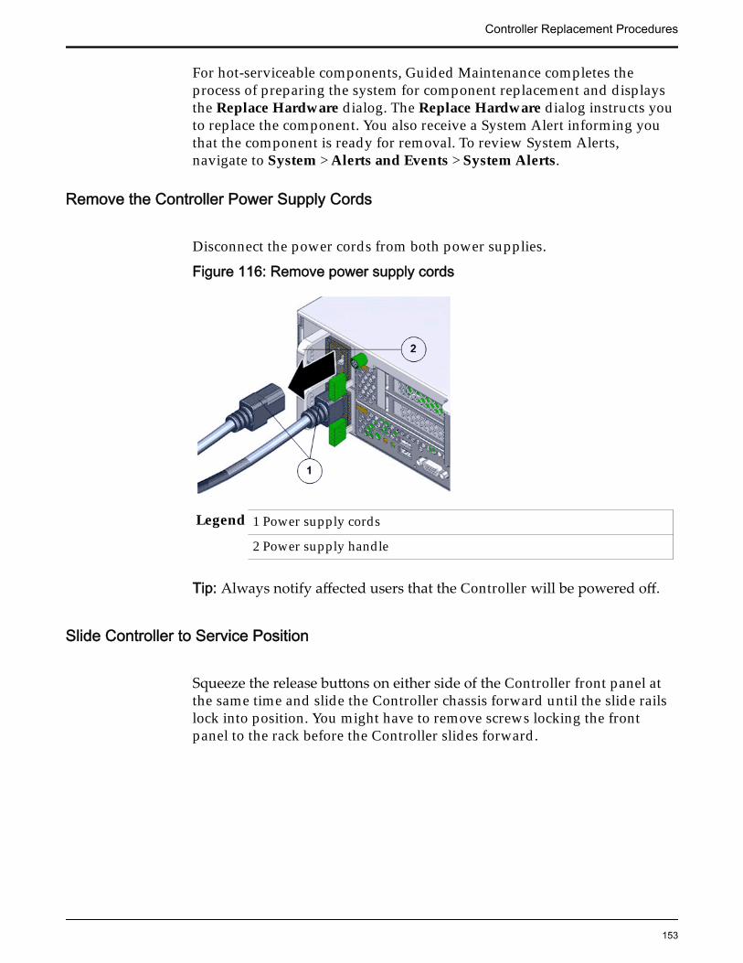
For hot-serviceable components, Guided Maintenance completes theprocess of preparing the system for component replacement and displaysthe Replace Hardware dialog. The Replace Hardware dialog instructs youto replace the component. You also receive a System Alert informing youthat the component is ready for removal. To review System Alerts,navigate to System > Alerts and Events > System Alerts.
Remove the Controller Power Supply Cords
Disconnect the power cords from both power supplies.
Figure 116: Remove power supply cords
Legend 1 Power supply cords
2 Power supply handle
Tip: Always notify affected users that the Controller will be powered off.
Slide Controller to Service Position
Squeeze the release buttons on either side of the Controller front panel atthe same time and slide the Controller chassis forward until the slide railslock into position. You might have to remove screws locking the frontpanel to the rack before the Controller slides forward.
Controller Replacement Procedures
153
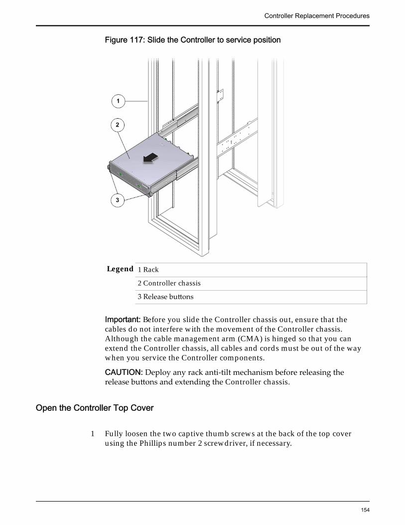
Figure 117: Slide the Controller to service position
Legend 1 Rack
2 Controller chassis
3 Release buttons
Important: Before you slide the Controller chassis out, ensure that thecables do not interfere with the movement of the Controller chassis.Although the cable management arm (CMA) is hinged so that you canextend the Controller chassis, all cables and cords must be out of the waywhen you service the Controller components.
CAUTION: Deploy any rack anti-tilt mechanism before releasing therelease buttons and extending the Controller chassis.
Open the Controller Top Cover
1 Fully loosen the two captive thumb screws at the back of the top coverusing the Phillips number 2 screwdriver, if necessary.
Controller Replacement Procedures
154
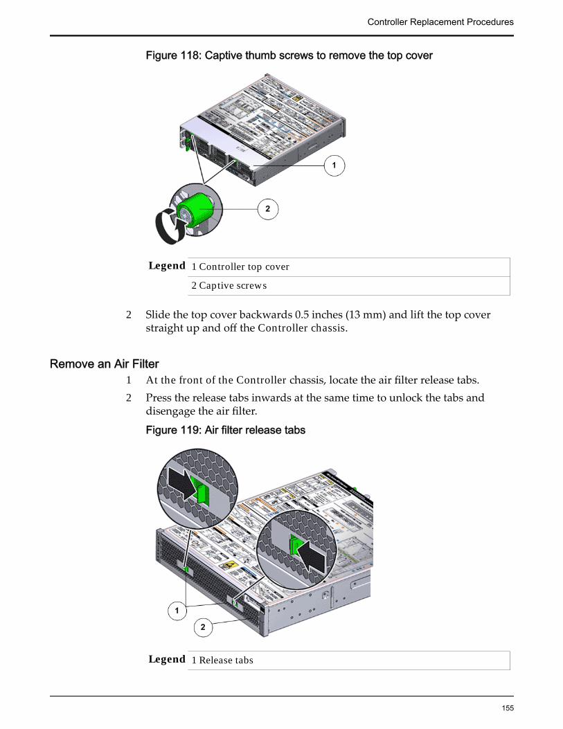
Figure 118: Captive thumb screws to remove the top cover
Legend 1 Controller top cover
2 Captive screws
2 Slide the top cover backwards 0.5 inches (13 mm) and lift the top coverstraight up and off the Controller chassis.
Remove an Air Filter1 At the front of the Controller chassis, locate the air filter release tabs.2 Press the release tabs inwards at the same time to unlock the tabs and
disengage the air filter.
Figure 119: Air filter release tabs
Legend 1 Release tabs
Controller Replacement Procedures
155
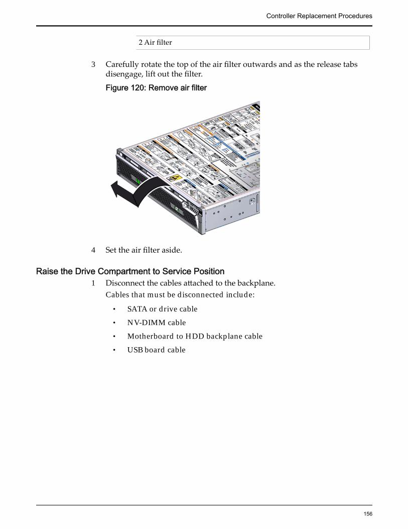
2 Air filter
3 Carefully rotate the top of the air filter outwards and as the release tabsdisengage, lift out the filter.
Figure 120: Remove air filter
4 Set the air filter aside.
Raise the Drive Compartment to Service Position1 Disconnect the cables attached to the backplane.
Cables that must be disconnected include:
• SATA or drive cable
• NV-DIMM cable
• Motherboard to HDD backplane cable
• USB board cable
Controller Replacement Procedures
156
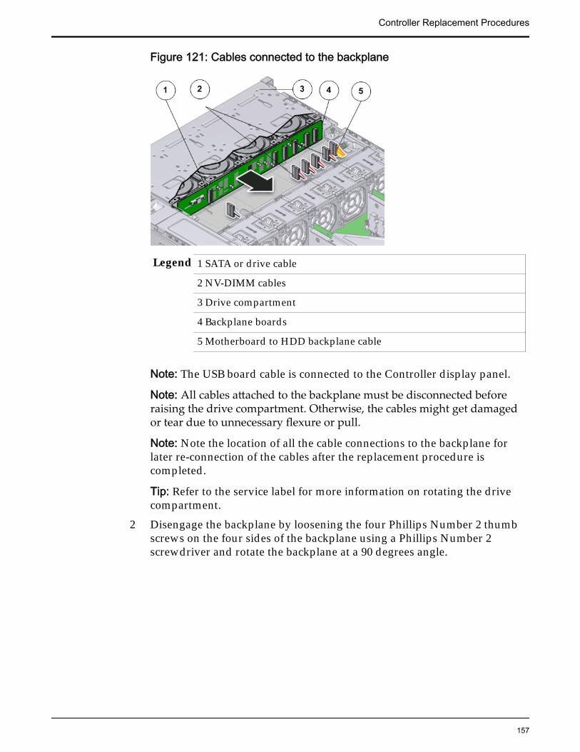
Figure 121: Cables connected to the backplane
Legend 1 SATA or drive cable
2 NV-DIMM cables
3 Drive compartment
4 Backplane boards
5 Motherboard to HDD backplane cable
Note: The USB board cable is connected to the Controller display panel.
Note: All cables attached to the backplane must be disconnected beforeraising the drive compartment. Otherwise, the cables might get damagedor tear due to unnecessary flexure or pull.
Note: Note the location of all the cable connections to the backplane forlater re-connection of the cables after the replacement procedure iscompleted.
Tip: Refer to the service label for more information on rotating the drivecompartment.
2 Disengage the backplane by loosening the four Phillips Number 2 thumbscrews on the four sides of the backplane using a Phillips Number 2screwdriver and rotate the backplane at a 90 degrees angle.
Controller Replacement Procedures
157
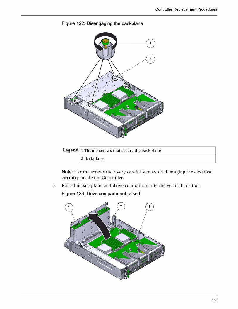
Figure 122: Disengaging the backplane
Legend 1 Thumb screws that secure the backplane
2 Backplane
Note: Use the screwdriver very carefully to avoid damaging the electricalcircuitry inside the Controller.
3 Raise the backplane and drive compartment to the vertical position.
Figure 123: Drive compartment raised
Controller Replacement Procedures
158
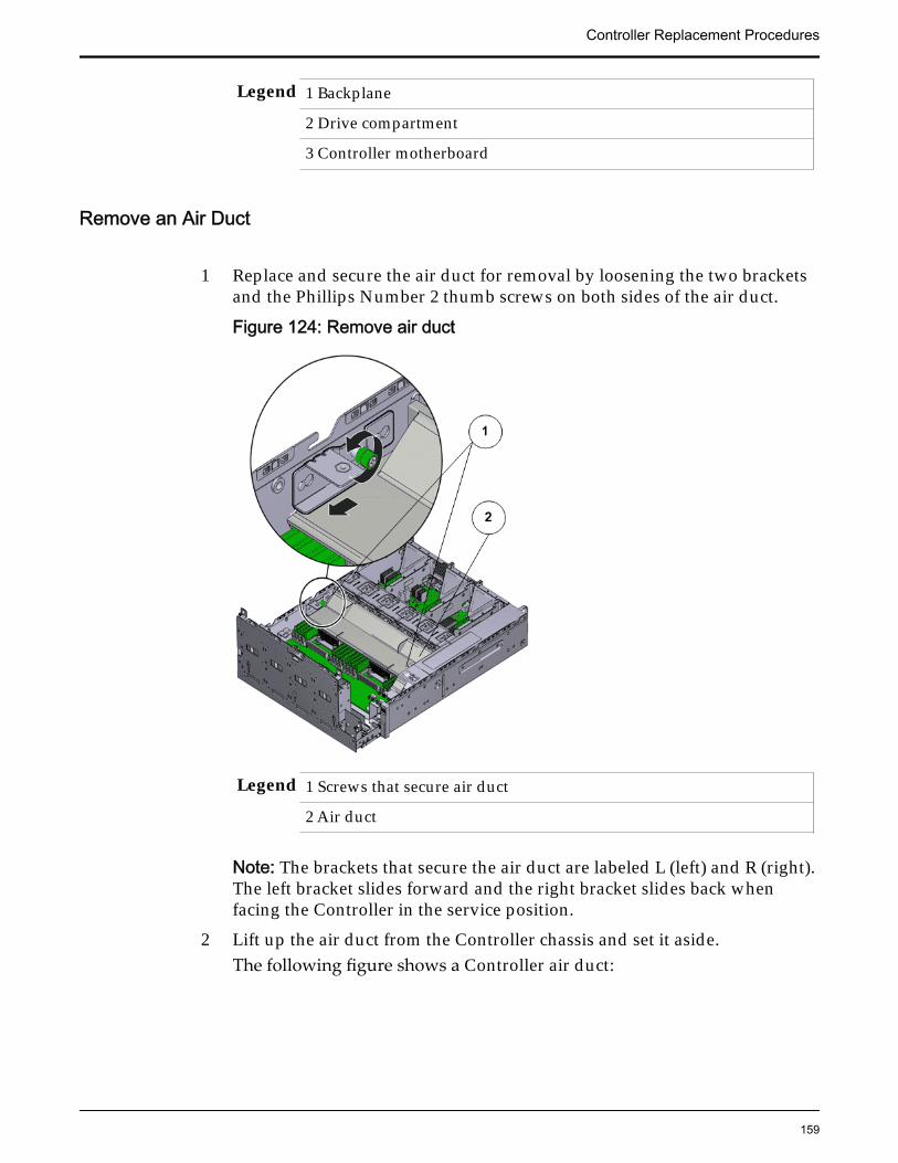
Legend 1 Backplane
2 Drive compartment
3 Controller motherboard
Remove an Air Duct
1 Replace and secure the air duct for removal by loosening the two bracketsand the Phillips Number 2 thumb screws on both sides of the air duct.
Figure 124: Remove air duct
Legend 1 Screws that secure air duct
2 Air duct
Note: The brackets that secure the air duct are labeled L (left) and R (right).The left bracket slides forward and the right bracket slides back whenfacing the Controller in the service position.
2 Lift up the air duct from the Controller chassis and set it aside.The following figure shows a Controller air duct:
Controller Replacement Procedures
159
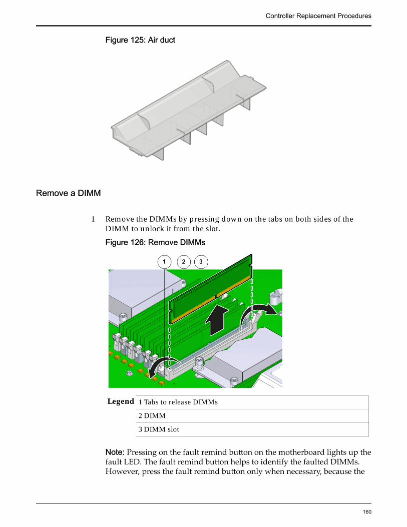
Figure 125: Air duct
Remove a DIMM
1 Remove the DIMMs by pressing down on the tabs on both sides of theDIMM to unlock it from the slot.
Figure 126: Remove DIMMs
Legend 1 Tabs to release DIMMs
2 DIMM
3 DIMM slot
Note: Pressing on the fault remind button on the motherboard lights up thefault LED. The fault remind button helps to identify the faulted DIMMs.However, press the fault remind button only when necessary, because the
Controller Replacement Procedures
160
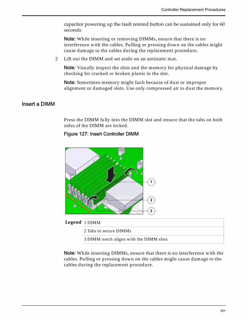
capacitor powering up the fault remind button can be sustained only for 60seconds.
Note: While inserting or removing DIMMs, ensure that there is nointerference with the cables. Pulling or pressing down on the cables mightcause damage to the cables during the replacement procedure.
2 Lift out the DIMM and set aside on an antistatic mat.
Note: Visually inspect the slots and the memory for physical damage bychecking for cracked or broken plastic in the slot.
Note: Sometimes memory might fault because of dust or improperalignment or damaged slots. Use only compressed air to dust the memory.
Insert a DIMM
Press the DIMM fully into the DIMM slot and ensure that the tabs on bothsides of the DIMM are locked.
Figure 127: Insert Controller DIMM
Legend 1 DIMM
2 Tabs to secure DIMMs
3 DIMM notch aligns with the DIMM slots
Note: While inserting DIMMs, ensure that there is no interference with thecables. Pulling or pressing down on the cables might cause damage to thecables during the replacement procedure.
Controller Replacement Procedures
161
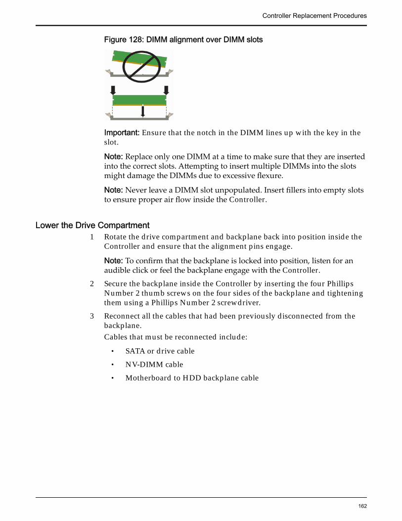
Figure 128: DIMM alignment over DIMM slots
Important: Ensure that the notch in the DIMM lines up with the key in theslot.
Note: Replace only one DIMM at a time to make sure that they are insertedinto the correct slots. Attempting to insert multiple DIMMs into the slotsmight damage the DIMMs due to excessive flexure.
Note: Never leave a DIMM slot unpopulated. Insert fillers into empty slotsto ensure proper air flow inside the Controller.
Lower the Drive Compartment1 Rotate the drive compartment and backplane back into position inside the
Controller and ensure that the alignment pins engage.
Note: To confirm that the backplane is locked into position, listen for anaudible click or feel the backplane engage with the Controller.
2 Secure the backplane inside the Controller by inserting the four PhillipsNumber 2 thumb screws on the four sides of the backplane and tighteningthem using a Phillips Number 2 screwdriver.
3 Reconnect all the cables that had been previously disconnected from thebackplane.Cables that must be reconnected include:
• SATA or drive cable
• NV-DIMM cable
• Motherboard to HDD backplane cable
Controller Replacement Procedures
162
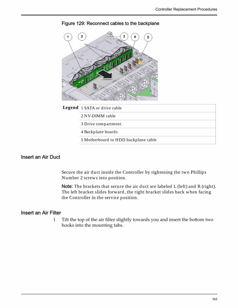
Figure 129: Reconnect cables to the backplane
Legend 1 SATA or drive cable
2 NV-DIMM cable
3 Drive compartment
4 Backplane boards
5 Motherboard to HDD backplane cable
Insert an Air Duct
Secure the air duct inside the Controller by tightening the two PhillipsNumber 2 screws into position.
Note: The brackets that secure the air duct are labeled L (left) and R (right).The left bracket slides forward, the right bracket slides back when facingthe Controller in the service position.
Insert an Air Filter1 Tilt the top of the air filter slightly towards you and insert the bottom two
hooks into the mounting tabs.
Controller Replacement Procedures
163
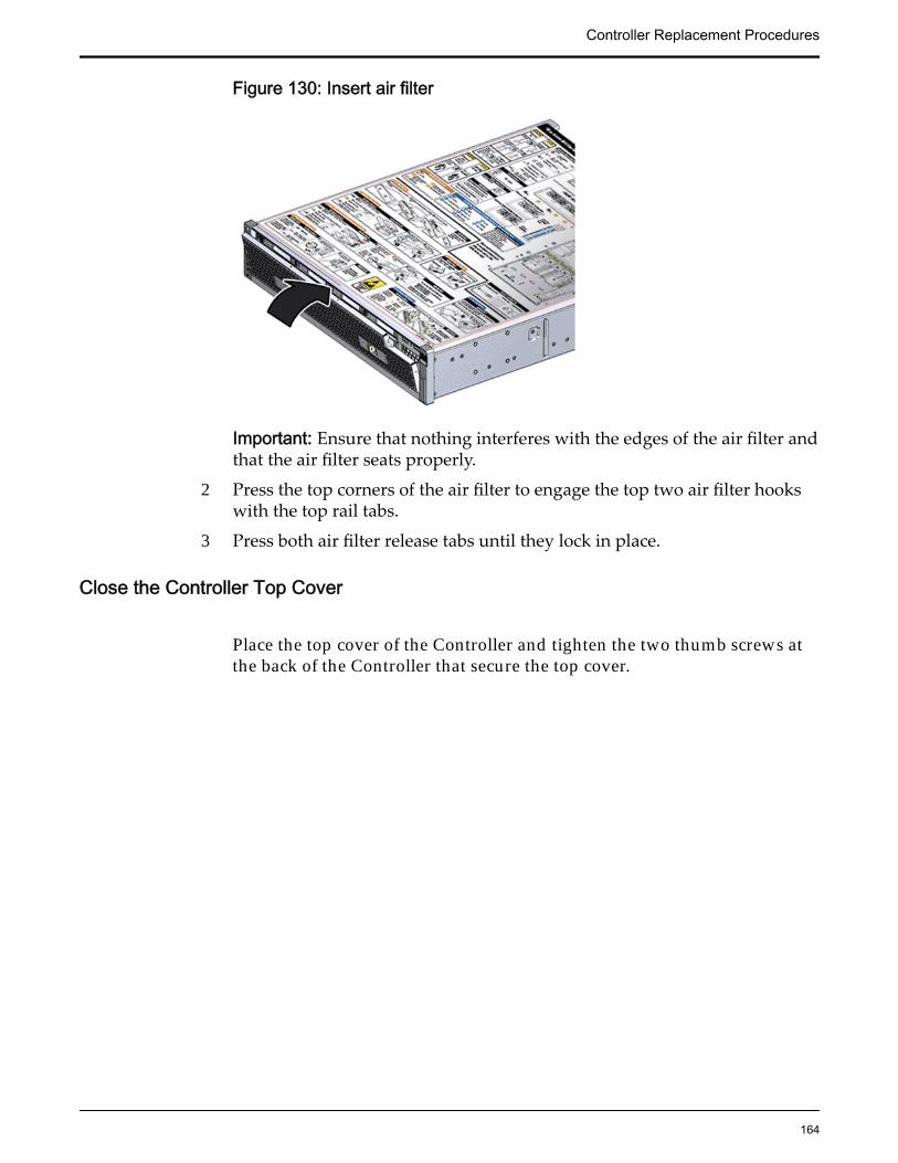
Figure 130: Insert air filter
Important: Ensure that nothing interferes with the edges of the air filter andthat the air filter seats properly.
2 Press the top corners of the air filter to engage the top two air filter hookswith the top rail tabs.
3 Press both air filter release tabs until they lock in place.
Close the Controller Top Cover
Place the top cover of the Controller and tighten the two thumb screws atthe back of the Controller that secure the top cover.
Controller Replacement Procedures
164
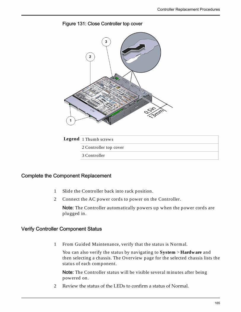
Figure 131: Close Controller top cover
Legend 1 Thumb screws
2 Controller top cover
3 Controller
Complete the Component Replacement
1 Slide the Controller back into rack position.
2 Connect the AC power cords to power on the Controller.
Note: The Controller automatically powers up when the power cords areplugged in.
Verify Controller Component Status
1 From Guided Maintenance, verify that the status is Normal.
You can also verify the status by navigating to System > Hardware andthen selecting a chassis. The Overview page for the selected chassis lists thestatus of each component.
Note: The Controller status will be visible several minutes after beingpowered on.
2 Review the status of the LEDs to confirm a status of Normal.
Controller Replacement Procedures
165
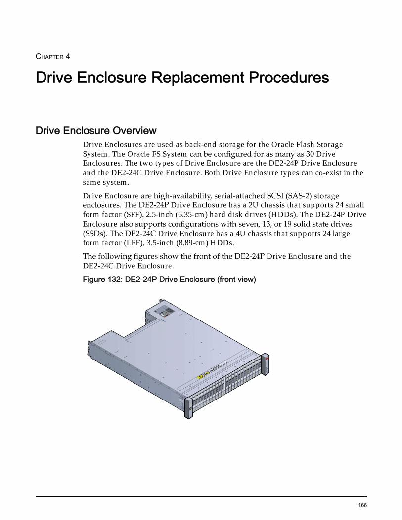
CHAPTER 4
Drive Enclosure Replacement Procedures
Drive Enclosure OverviewDrive Enclosures are used as back-end storage for the Oracle Flash StorageSystem. The Oracle FS System can be configured for as many as 30 DriveEnclosures. The two types of Drive Enclosure are the DE2-24P Drive Enclosureand the DE2-24C Drive Enclosure. Both Drive Enclosure types can co-exist in thesame system.
Drive Enclosure are high-availability, serial-attached SCSI (SAS-2) storageenclosures. The DE2-24P Drive Enclosure has a 2U chassis that supports 24 smallform factor (SFF), 2.5-inch (6.35-cm) hard disk drives (HDDs). The DE2-24P DriveEnclosure also supports configurations with seven, 13, or 19 solid state drives(SSDs). The DE2-24C Drive Enclosure has a 4U chassis that supports 24 largeform factor (LFF), 3.5-inch (8.89-cm) HDDs.
The following figures show the front of the DE2-24P Drive Enclosure and theDE2-24C Drive Enclosure.
Figure 132: DE2-24P Drive Enclosure (front view)
166
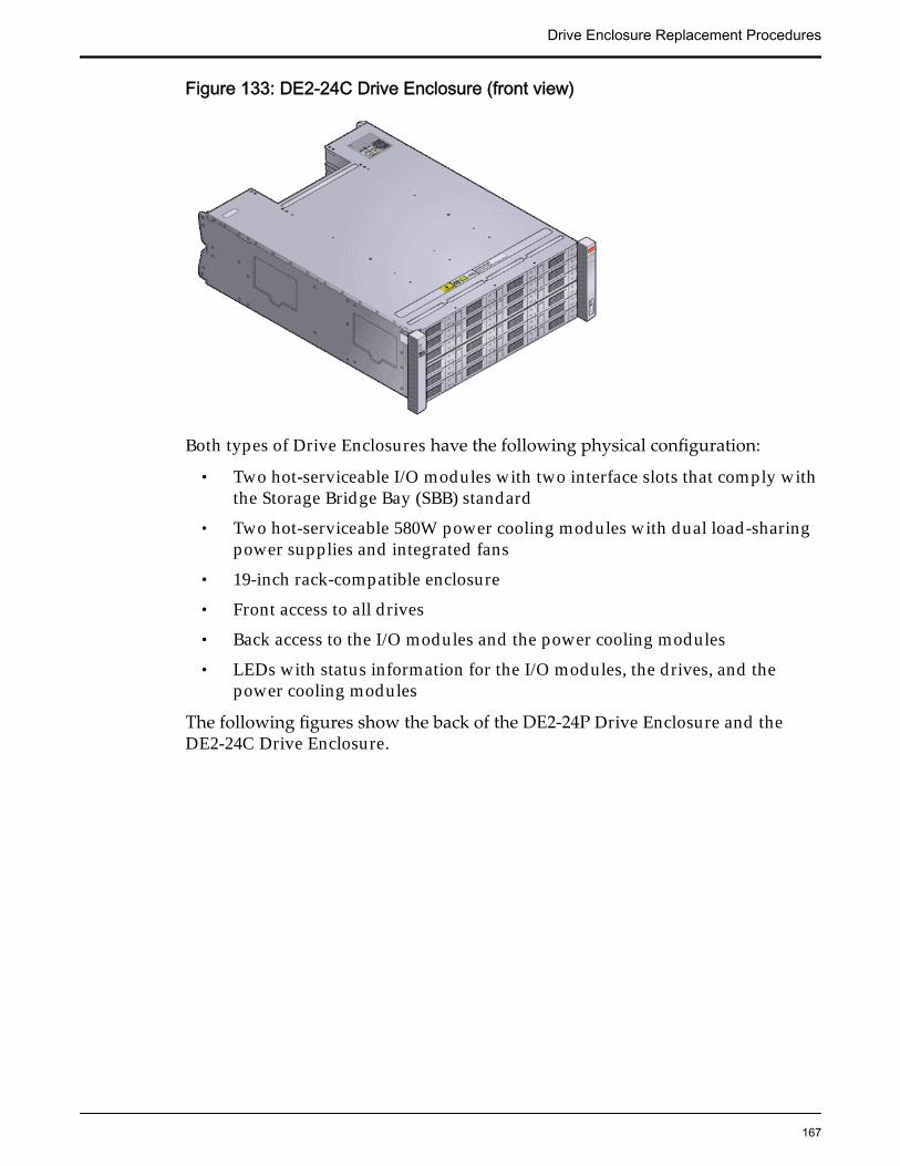
Figure 133: DE2-24C Drive Enclosure (front view)
Both types of Drive Enclosures have the following physical configuration:
• Two hot-serviceable I/O modules with two interface slots that comply withthe Storage Bridge Bay (SBB) standard
• Two hot-serviceable 580W power cooling modules with dual load-sharingpower supplies and integrated fans
• 19-inch rack‑compatible enclosure
• Front access to all drives
• Back access to the I/O modules and the power cooling modules
• LEDs with status information for the I/O modules, the drives, and thepower cooling modules
The following figures show the back of the DE2-24P Drive Enclosure and theDE2-24C Drive Enclosure.
Drive Enclosure Replacement Procedures
167
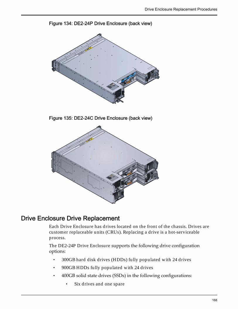
Figure 134: DE2-24P Drive Enclosure (back view)
Figure 135: DE2-24C Drive Enclosure (back view)
Drive Enclosure Drive ReplacementEach Drive Enclosure has drives located on the front of the chassis. Drives arecustomer replaceable units (CRUs). Replacing a drive is a hot-serviceableprocess.
The DE2-24P Drive Enclosure supports the following drive configurationoptions:
• 300GB hard disk drives (HDDs) fully populated with 24 drives
• 900GB HDDs fully populated with 24 drives
• 400GB solid state drives (SSDs) in the following configurations:
• Six drives and one spare
Drive Enclosure Replacement Procedures
168
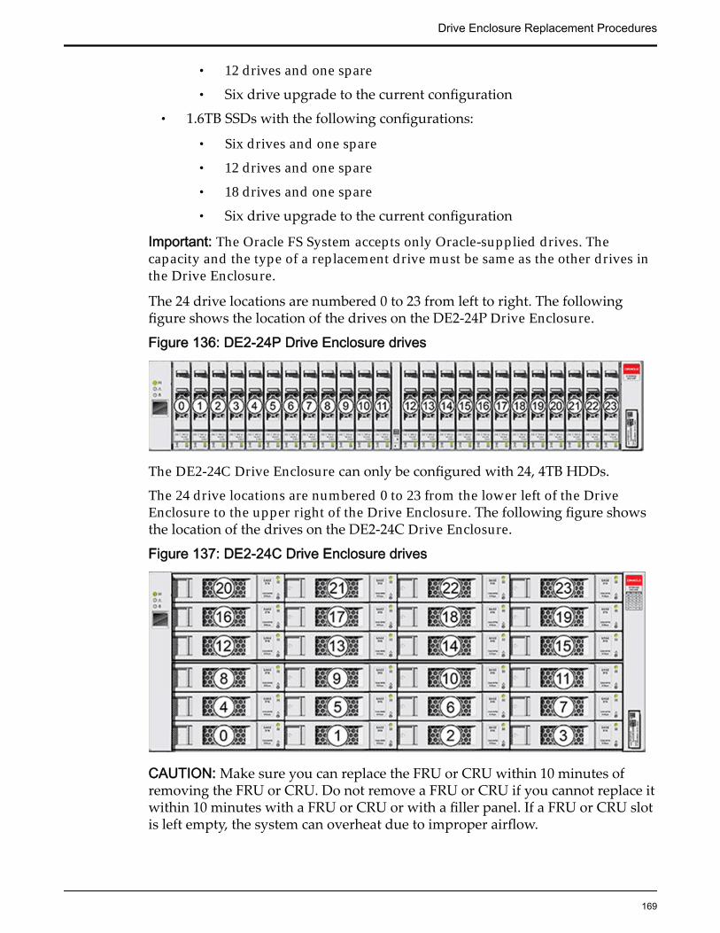
• 12 drives and one spare
• Six drive upgrade to the current configuration
• 1.6TB SSDs with the following configurations:
• Six drives and one spare
• 12 drives and one spare
• 18 drives and one spare
• Six drive upgrade to the current configuration
Important: The Oracle FS System accepts only Oracle-supplied drives. Thecapacity and the type of a replacement drive must be same as the other drives inthe Drive Enclosure.
The 24 drive locations are numbered 0 to 23 from left to right. The followingfigure shows the location of the drives on the DE2-24P Drive Enclosure.
Figure 136: DE2-24P Drive Enclosure drives
The DE2-24C Drive Enclosure can only be configured with 24, 4TB HDDs.
The 24 drive locations are numbered 0 to 23 from the lower left of the DriveEnclosure to the upper right of the Drive Enclosure. The following figure showsthe location of the drives on the DE2-24C Drive Enclosure.
Figure 137: DE2-24C Drive Enclosure drives
CAUTION: Make sure you can replace the FRU or CRU within 10 minutes ofremoving the FRU or CRU. Do not remove a FRU or CRU if you cannot replace itwithin 10 minutes with a FRU or CRU or with a filler panel. If a FRU or CRU slotis left empty, the system can overheat due to improper airflow.
Drive Enclosure Replacement Procedures
169
Important: Make sure that you remove the correct drive. Removing a drive otherthan the failed drive can disrupt data access and possibly corrupt data.
The system generates an alert to notify you of a failed drive. The system alsonotifies you when it detects that a drive might fail soon.
Replace a Drive Enclosure DriveA failed Drive Enclosure drive degrades data throughput. Additionally, if morethan one drive begins to fail, data loss can occur. Replace a failed drive with adrive of the same type and capacity as soon as possible.
Prerequisites: • Before handling a component, touch a grounded surface todischarge any static electricity.
• Attach an electrostatic discharge (ESD) wrist strap to yourwrist, and stand on an ESD mat while replacingcomponents.
• Make sure that the replacement drive has the samecapacity and same type as the drive to be replaced.
Important: After you initiate Guided Maintenance to prepare the system forreplacing a drive, you must complete the procedure. Do not cancel thereplacement process after the replacement process has started. Canceling thereplacement process can result in loss of data.
Procedure Overview
1 Prepare a Drive Enclosure for Component Replacement
2 Remove a Drive
3 Insert a Drive
4 Verify the Status of a Drive Enclosure Component
Prepare a Drive Enclosure for Component Replacement1 From Oracle FS System Manager (GUI), navigate to System > Hardware.
2 Select Drive Enclosures.The GUI displays the Drive Enclosures Overview page. The DriveEnclosures Overview page displays the status of the Drive Enclosurecomponents.
3 Select the Drive Enclosure containing the component that you want toreplace.
4 Select Actions > View.The View Drive Enclosure dialog displays the list of replaceable DriveEnclosure components in the Replaceable Unit list.
5 From the Replaceable Unit list, select the component that you want toreplace and click Replace Component.
Drive Enclosure Replacement Procedures
170
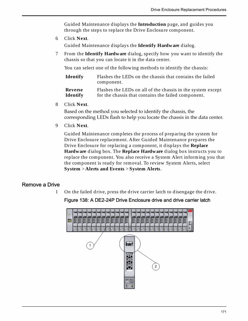
Guided Maintenance displays the Introduction page, and guides youthrough the steps to replace the Drive Enclosure component.
6 Click Next.Guided Maintenance displays the Identify Hardware dialog.
7 From the Identify Hardware dialog, specify how you want to identify thechassis so that you can locate it in the data center.
You can select one of the following methods to identify the chassis:
Identify Flashes the LEDs on the chassis that contains the failedcomponent.
ReverseIdentify
Flashes the LEDs on all of the chassis in the system exceptfor the chassis that contains the failed component.
8 Click Next.Based on the method you selected to identify the chassis, thecorresponding LEDs flash to help you locate the chassis in the data center.
9 Click Next.
Guided Maintenance completes the process of preparing the system forDrive Enclosure replacement. After Guided Maintenance prepares theDrive Enclosure for replacing a component, it displays the ReplaceHardware dialog box. The Replace Hardware dialog box instructs you toreplace the component. You also receive a System Alert informing you thatthe component is ready for removal. To review System Alerts, selectSystem > Alerts and Events > System Alerts.
Remove a Drive1 On the failed drive, press the drive carrier latch to disengage the drive.
Figure 138: A DE2-24P Drive Enclosure drive and drive carrier latch
Drive Enclosure Replacement Procedures
171
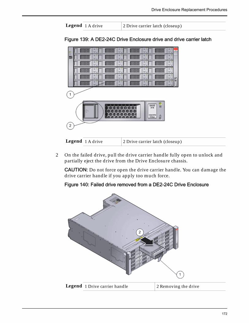
Legend 1 A drive 2 Drive carrier latch (closeup)
Figure 139: A DE2-24C Drive Enclosure drive and drive carrier latch
Legend 1 A drive 2 Drive carrier latch (closeup)
2 On the failed drive, pull the drive carrier handle fully open to unlock andpartially eject the drive from the Drive Enclosure chassis.
CAUTION: Do not force open the drive carrier handle. You can damage thedrive carrier handle if you apply too much force.
Figure 140: Failed drive removed from a DE2-24C Drive Enclosure
Legend 1 Drive carrier handle 2 Removing the drive
Drive Enclosure Replacement Procedures
172
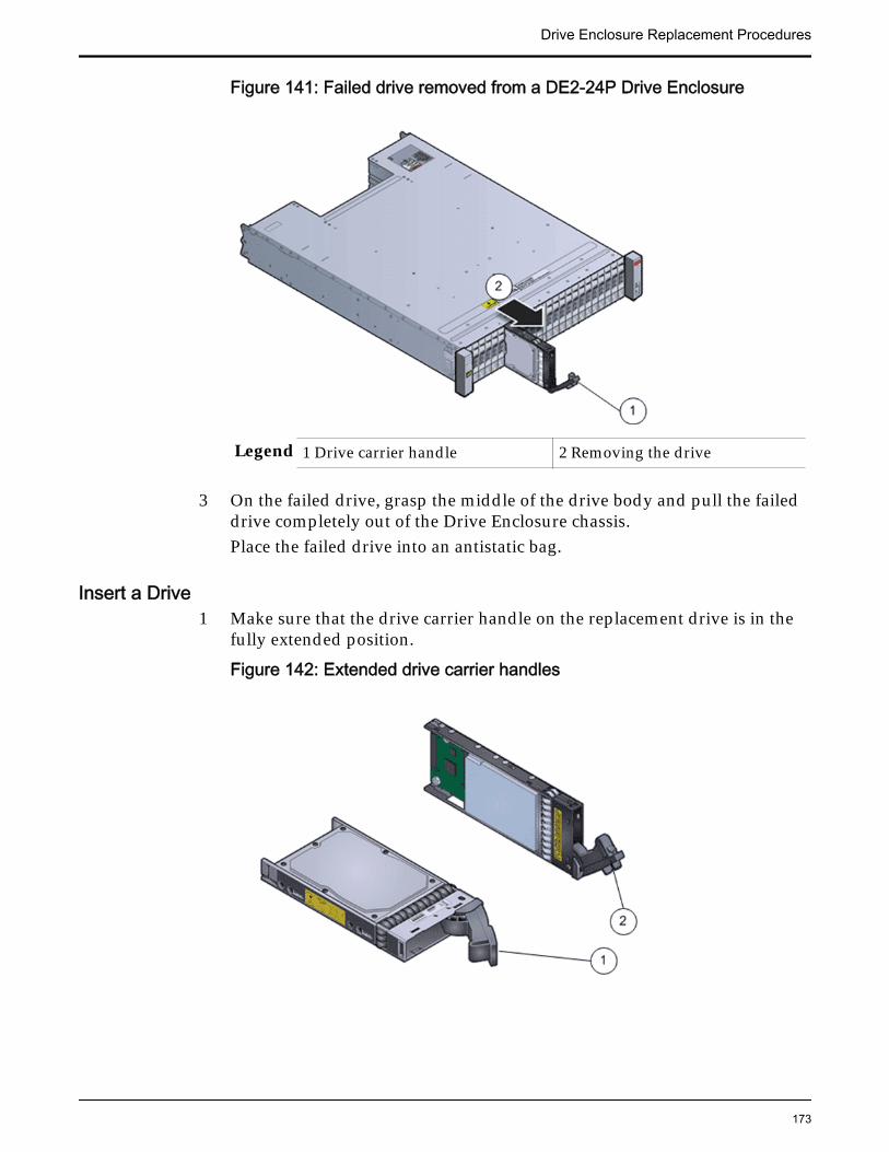
Figure 141: Failed drive removed from a DE2-24P Drive Enclosure
Legend 1 Drive carrier handle 2 Removing the drive
3 On the failed drive, grasp the middle of the drive body and pull the faileddrive completely out of the Drive Enclosure chassis.Place the failed drive into an antistatic bag.
Insert a Drive1 Make sure that the drive carrier handle on the replacement drive is in the
fully extended position.
Figure 142: Extended drive carrier handles
Drive Enclosure Replacement Procedures
173
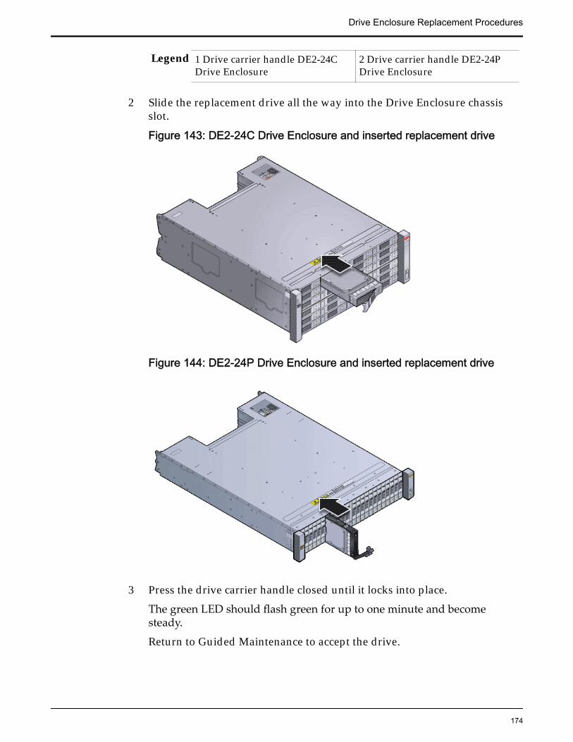
Legend 1 Drive carrier handle DE2-24CDrive Enclosure
2 Drive carrier handle DE2-24PDrive Enclosure
2 Slide the replacement drive all the way into the Drive Enclosure chassisslot.
Figure 143: DE2-24C Drive Enclosure and inserted replacement drive
Figure 144: DE2-24P Drive Enclosure and inserted replacement drive
3 Press the drive carrier handle closed until it locks into place.
The green LED should flash green for up to one minute and becomesteady.
Return to Guided Maintenance to accept the drive.
Drive Enclosure Replacement Procedures
174
Verify the Status of a Drive Enclosure Component1 From Guided Maintenance, verify that the status of the component is
Normal.
Guided Maintenance displays a message stating the component status. Astatus of Normal requires no action.
2 Close Guided Maintenance.You can also verify component status by navigating to System >Hardware > Drive Enclosures. The Drive Enclosure overview page liststhe status of each component.
Replace an I/O ModuleI/O modules provide the input and output transfer of data. While a single I/Omodule failure does not impact data availability, two I/O module failuresdegrade data traffic and connectivity. Replace a failed I/O module as soon aspossible.
Prerequisites: • Before handling a component, touch a grounded surface todischarge any static electricity.
• Attach an electrostatic discharge (ESD) wrist strap to yourwrist, and stand on an ESD mat while replacingcomponents.
Each Drive Enclosure has two I/O modules located at the back of the DriveEnclosure. I/O modules are customer replaceable units (CRUs). You can replace afailed I/O module without powering down the Drive Enclosure only if the otherI/O module is operational with a status of Normal.
The following figure shows the I/O modules on the back of the DE2-24P andDE2-24C Drive Enclosure types.
Note: Notice that I/O module 0 in the DE2-24P Drive Enclosure is inverted.
Drive Enclosure Replacement Procedures
175
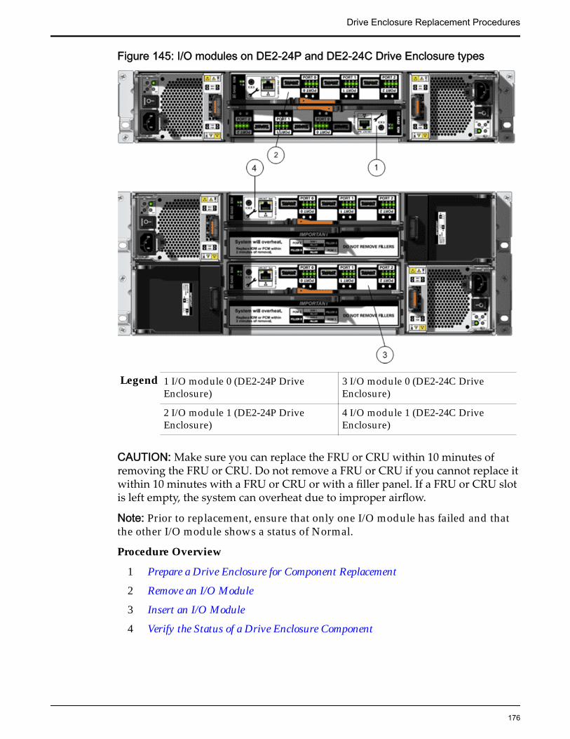
Figure 145: I/O modules on DE2-24P and DE2-24C Drive Enclosure types
Legend 1 I/O module 0 (DE2-24P DriveEnclosure)
3 I/O module 0 (DE2-24C DriveEnclosure)
2 I/O module 1 (DE2-24P DriveEnclosure)
4 I/O module 1 (DE2-24C DriveEnclosure)
CAUTION: Make sure you can replace the FRU or CRU within 10 minutes ofremoving the FRU or CRU. Do not remove a FRU or CRU if you cannot replace itwithin 10 minutes with a FRU or CRU or with a filler panel. If a FRU or CRU slotis left empty, the system can overheat due to improper airflow.
Note: Prior to replacement, ensure that only one I/O module has failed and thatthe other I/O module shows a status of Normal.
Procedure Overview
1 Prepare a Drive Enclosure for Component Replacement
2 Remove an I/O Module
3 Insert an I/O Module
4 Verify the Status of a Drive Enclosure Component
Drive Enclosure Replacement Procedures
176
Prepare a Drive Enclosure for Component Replacement1 From Oracle FS System Manager (GUI), navigate to System > Hardware.
2 Select Drive Enclosures.The GUI displays the Drive Enclosures Overview page. The DriveEnclosures Overview page displays the status of the Drive Enclosurecomponents.
3 Select the Drive Enclosure containing the component that you want toreplace.
4 Select Actions > View.The View Drive Enclosure dialog displays the list of replaceable DriveEnclosure components in the Replaceable Unit list.
5 From the Replaceable Unit list, select the component that you want toreplace and click Replace Component.Guided Maintenance displays the Introduction page, and guides youthrough the steps to replace the Drive Enclosure component.
6 Click Next.Guided Maintenance displays the Identify Hardware dialog.
7 From the Identify Hardware dialog, specify how you want to identify thechassis so that you can locate it in the data center.
You can select one of the following methods to identify the chassis:
Identify Flashes the LEDs on the chassis that contains the failedcomponent.
ReverseIdentify
Flashes the LEDs on all of the chassis in the system exceptfor the chassis that contains the failed component.
8 Click Next.Based on the method you selected to identify the chassis, thecorresponding LEDs flash to help you locate the chassis in the data center.
9 Click Next.
Guided Maintenance completes the process of preparing the system forDrive Enclosure replacement. After Guided Maintenance prepares theDrive Enclosure for replacing a component, it displays the ReplaceHardware dialog box. The Replace Hardware dialog box instructs you toreplace the component. You also receive a System Alert informing you thatthe component is ready for removal. To review System Alerts, selectSystem > Alerts and Events > System Alerts.
Remove an I/O Module1 When Guided Maintenance prompts you to remove the component, label
and disconnect the SAS interface cables that are attached to the I/Omodule.
Drive Enclosure Replacement Procedures
177
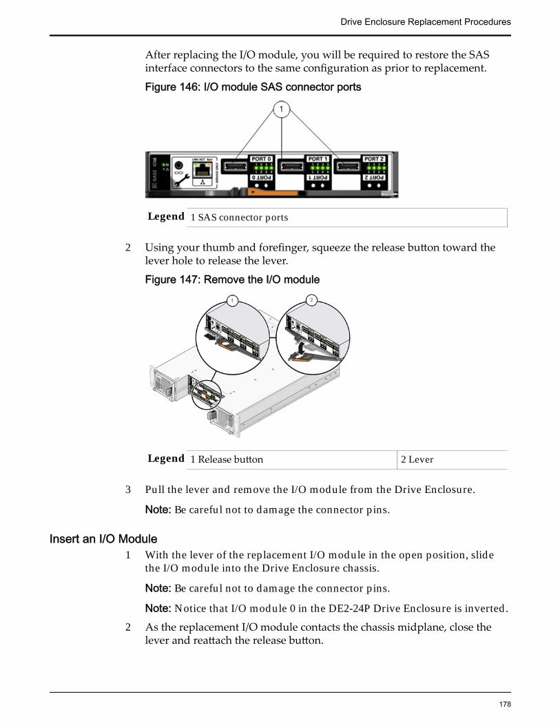
After replacing the I/O module, you will be required to restore the SASinterface connectors to the same configuration as prior to replacement.
Figure 146: I/O module SAS connector ports
Legend 1 SAS connector ports
2 Using your thumb and forefinger, squeeze the release button toward thelever hole to release the lever.
Figure 147: Remove the I/O module
Legend 1 Release button 2 Lever
3 Pull the lever and remove the I/O module from the Drive Enclosure.
Note: Be careful not to damage the connector pins.
Insert an I/O Module1 With the lever of the replacement I/O module in the open position, slide
the I/O module into the Drive Enclosure chassis.
Note: Be careful not to damage the connector pins.
Note: Notice that I/O module 0 in the DE2-24P Drive Enclosure is inverted.
2 As the replacement I/O module contacts the chassis midplane, close thelever and reattach the release button.
Drive Enclosure Replacement Procedures
178
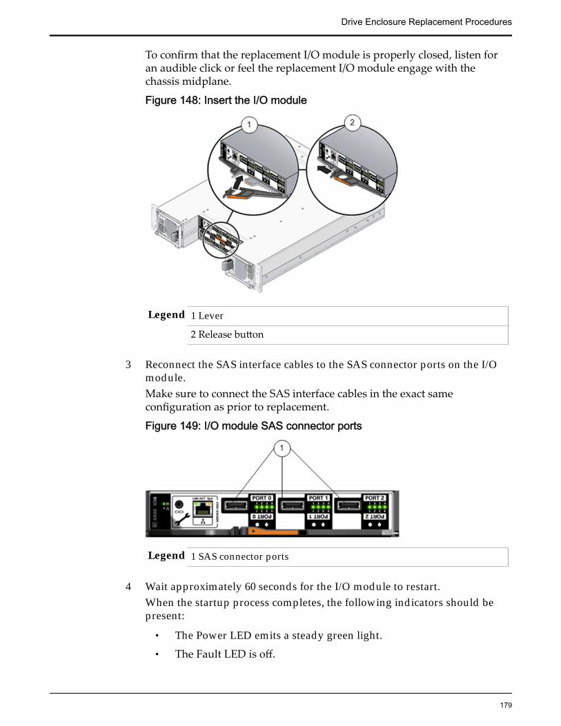
To confirm that the replacement I/O module is properly closed, listen foran audible click or feel the replacement I/O module engage with thechassis midplane.
Figure 148: Insert the I/O module
Legend 1 Lever
2 Release button
3 Reconnect the SAS interface cables to the SAS connector ports on the I/Omodule.Make sure to connect the SAS interface cables in the exact sameconfiguration as prior to replacement.
Figure 149: I/O module SAS connector ports
Legend 1 SAS connector ports
4 Wait approximately 60 seconds for the I/O module to restart.When the startup process completes, the following indicators should bepresent:
• The Power LED emits a steady green light.
• The Fault LED is off.
Drive Enclosure Replacement Procedures
179
• All four Activity LEDs emit a green light for each SAS-2 port that hasan SAS interface cable connected to it.
Verify the Status of a Drive Enclosure Component1 From Guided Maintenance, verify that the status of the component is
Normal.
Guided Maintenance displays a message stating the component status. Astatus of Normal requires no action.
2 Close Guided Maintenance.You can also verify component status by navigating to System >Hardware > Drive Enclosures. The Drive Enclosure overview page liststhe status of each component.
Replace a Power Cooling ModuleThe power cooling modules provide redundant power control and cooling of thesystem. If one power cooling module fails, the other power cooling modulemaintains the power supply and cooling while you replace the failed powercooling module. Electrical overload, inadequate internal and external airflow,dirt and dust, incorrect input voltage, or a short circuit can damage a powercooling module. Replace a failed power cooling module immediately; otherwise,damage from overheating and data loss can occur.
Prerequisites: • Before handling a component, touch a grounded surface todischarge any static electricity.
• Attach an electrostatic discharge (ESD) wrist strap to yourwrist, and stand on an ESD mat while replacingcomponents.
WARNING: Do not remove covers from the power coolingmodules. Power cooling modules produce a high-energy hazard.
Each Drive Enclosure has two power cooling modules located at the back of theDrive Enclosure. Power cooling modules are customer replaceable units (CRUs).You can replace a failed power cooling module without powering down theDrive Enclosure only if the other power cooling module is operational with astatus of Normal.
The following figure shows the power cooling modules on the DE2-24P DriveEnclosure and the DE2-24C Drive Enclosure.
Drive Enclosure Replacement Procedures
180
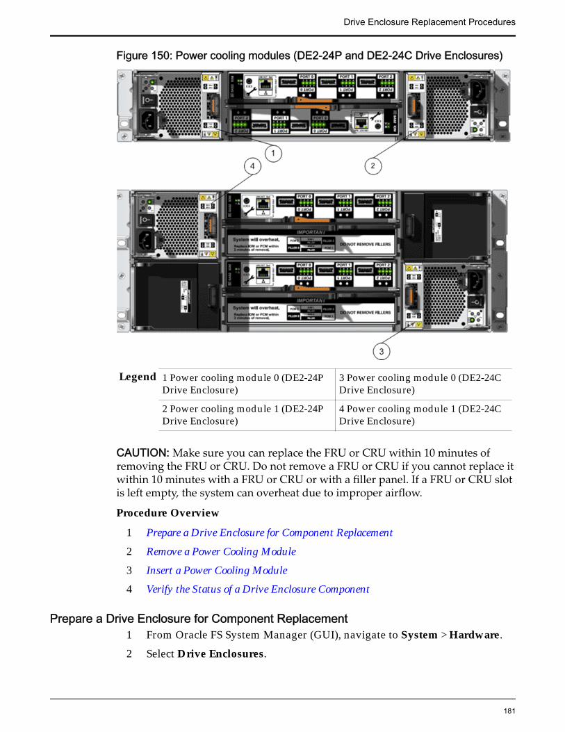
Figure 150: Power cooling modules (DE2-24P and DE2-24C Drive Enclosures)
Legend 1 Power cooling module 0 (DE2-24PDrive Enclosure)
3 Power cooling module 0 (DE2-24CDrive Enclosure)
2 Power cooling module 1 (DE2-24PDrive Enclosure)
4 Power cooling module 1 (DE2-24CDrive Enclosure)
CAUTION: Make sure you can replace the FRU or CRU within 10 minutes ofremoving the FRU or CRU. Do not remove a FRU or CRU if you cannot replace itwithin 10 minutes with a FRU or CRU or with a filler panel. If a FRU or CRU slotis left empty, the system can overheat due to improper airflow.
Procedure Overview
1 Prepare a Drive Enclosure for Component Replacement
2 Remove a Power Cooling Module
3 Insert a Power Cooling Module
4 Verify the Status of a Drive Enclosure Component
Prepare a Drive Enclosure for Component Replacement1 From Oracle FS System Manager (GUI), navigate to System > Hardware.
2 Select Drive Enclosures.
Drive Enclosure Replacement Procedures
181
The GUI displays the Drive Enclosures Overview page. The DriveEnclosures Overview page displays the status of the Drive Enclosurecomponents.
3 Select the Drive Enclosure containing the component that you want toreplace.
4 Select Actions > View.The View Drive Enclosure dialog displays the list of replaceable DriveEnclosure components in the Replaceable Unit list.
5 From the Replaceable Unit list, select the component that you want toreplace and click Replace Component.Guided Maintenance displays the Introduction page, and guides youthrough the steps to replace the Drive Enclosure component.
6 Click Next.Guided Maintenance displays the Identify Hardware dialog.
7 From the Identify Hardware dialog, specify how you want to identify thechassis so that you can locate it in the data center.
You can select one of the following methods to identify the chassis:
Identify Flashes the LEDs on the chassis that contains the failedcomponent.
ReverseIdentify
Flashes the LEDs on all of the chassis in the system exceptfor the chassis that contains the failed component.
8 Click Next.Based on the method you selected to identify the chassis, thecorresponding LEDs flash to help you locate the chassis in the data center.
9 Click Next.
Guided Maintenance completes the process of preparing the system forDrive Enclosure replacement. After Guided Maintenance prepares theDrive Enclosure for replacing a component, it displays the ReplaceHardware dialog box. The Replace Hardware dialog box instructs you toreplace the component. You also receive a System Alert informing you thatthe component is ready for removal. To review System Alerts, selectSystem > Alerts and Events > System Alerts.
Remove a Power Cooling Module1 When Guided Maintenance prompts you to remove the component, power
off the failed power cooling module.
Note: Do not power off the healthy power cooling module.2 Disconnect the power cord tie strap from the faulted power cooling
module.3 Unplug the power cord from the failed power cooling module.
Drive Enclosure Replacement Procedures
182
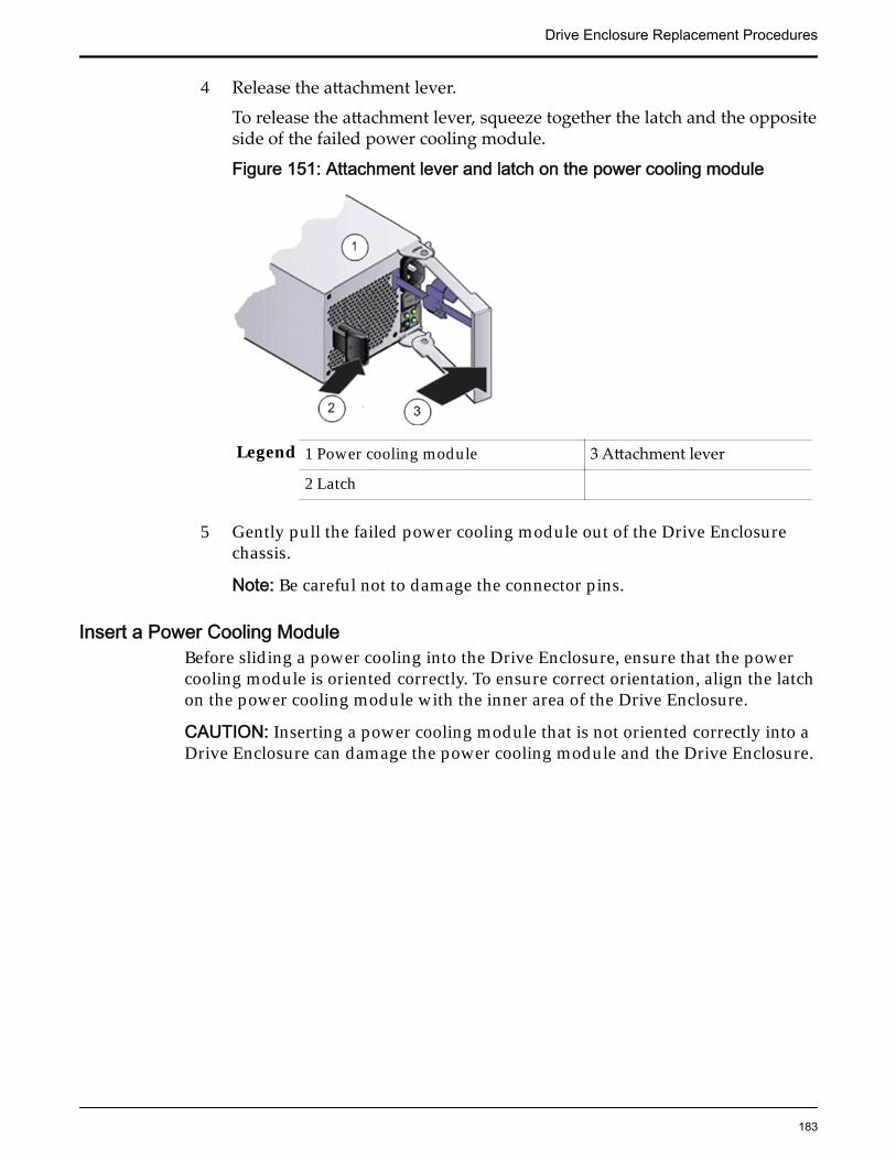
4 Release the attachment lever.
To release the attachment lever, squeeze together the latch and the oppositeside of the failed power cooling module.
Figure 151: Attachment lever and latch on the power cooling module
Legend 1 Power cooling module 3 Attachment lever
2 Latch
5 Gently pull the failed power cooling module out of the Drive Enclosurechassis.
Note: Be careful not to damage the connector pins.
Insert a Power Cooling ModuleBefore sliding a power cooling into the Drive Enclosure, ensure that the powercooling module is oriented correctly. To ensure correct orientation, align the latchon the power cooling module with the inner area of the Drive Enclosure.
CAUTION: Inserting a power cooling module that is not oriented correctly into aDrive Enclosure can damage the power cooling module and the Drive Enclosure.
Drive Enclosure Replacement Procedures
183
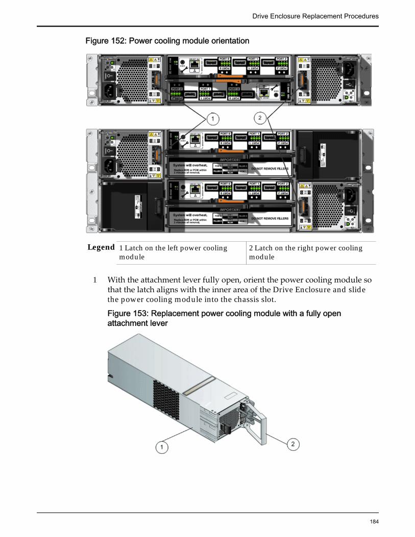
Figure 152: Power cooling module orientation
Legend 1 Latch on the left power coolingmodule
2 Latch on the right power coolingmodule
1 With the attachment lever fully open, orient the power cooling module sothat the latch aligns with the inner area of the Drive Enclosure and slidethe power cooling module into the chassis slot.
Figure 153: Replacement power cooling module with a fully openattachment lever
Drive Enclosure Replacement Procedures
184
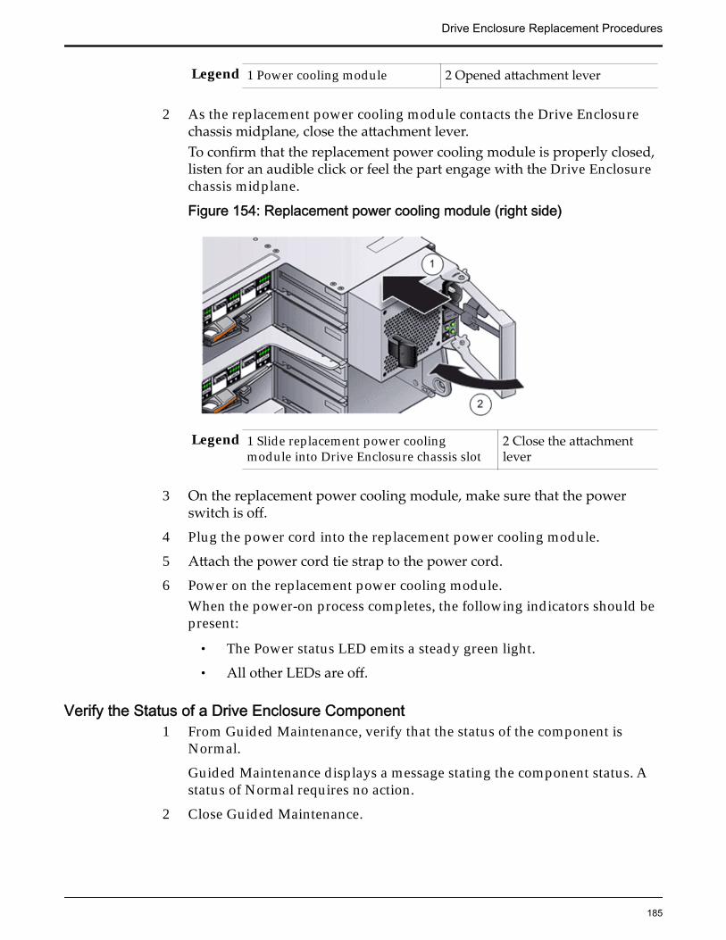
Legend 1 Power cooling module 2 Opened attachment lever
2 As the replacement power cooling module contacts the Drive Enclosurechassis midplane, close the attachment lever.To confirm that the replacement power cooling module is properly closed,listen for an audible click or feel the part engage with the Drive Enclosurechassis midplane.
Figure 154: Replacement power cooling module (right side)
Legend 1 Slide replacement power coolingmodule into Drive Enclosure chassis slot
2 Close the attachmentlever
3 On the replacement power cooling module, make sure that the powerswitch is off.
4 Plug the power cord into the replacement power cooling module.
5 Attach the power cord tie strap to the power cord.
6 Power on the replacement power cooling module.When the power-on process completes, the following indicators should bepresent:
• The Power status LED emits a steady green light.
• All other LEDs are off.
Verify the Status of a Drive Enclosure Component1 From Guided Maintenance, verify that the status of the component is
Normal.
Guided Maintenance displays a message stating the component status. Astatus of Normal requires no action.
2 Close Guided Maintenance.
Drive Enclosure Replacement Procedures
185

You can also verify component status by navigating to System >Hardware > Drive Enclosures. The Drive Enclosure overview page liststhe status of each component.
Drive Enclosure Replacement Procedures
186
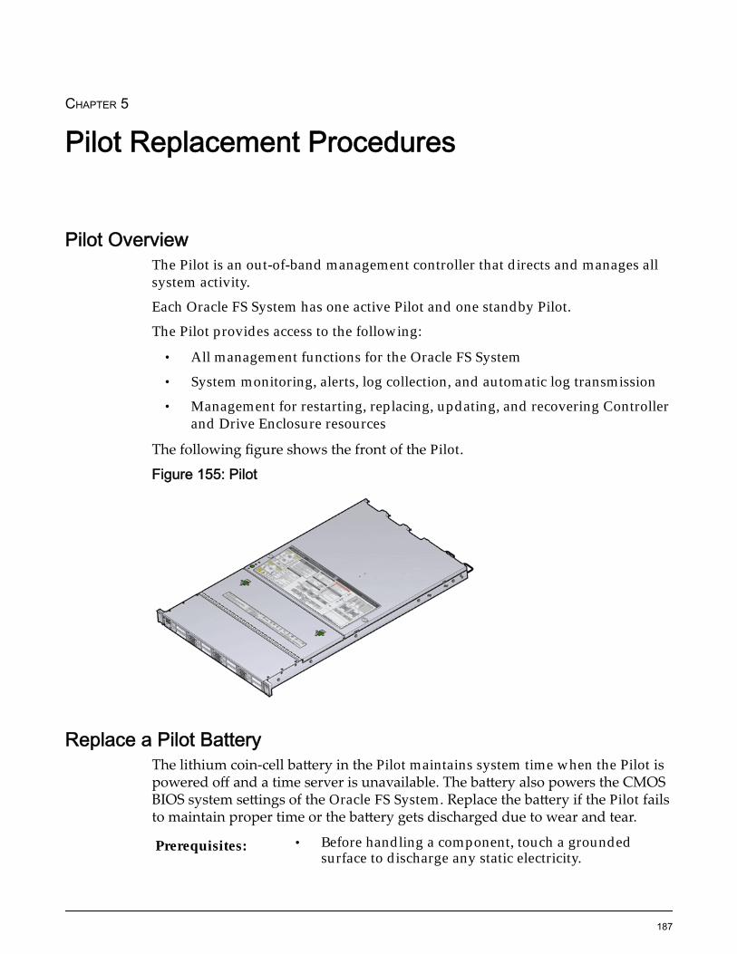
CHAPTER 5
Pilot Replacement Procedures
Pilot OverviewThe Pilot is an out-of-band management controller that directs and manages allsystem activity.
Each Oracle FS System has one active Pilot and one standby Pilot.
The Pilot provides access to the following:
• All management functions for the Oracle FS System
• System monitoring, alerts, log collection, and automatic log transmission
• Management for restarting, replacing, updating, and recovering Controllerand Drive Enclosure resources
The following figure shows the front of the Pilot.
Figure 155: Pilot
Replace a Pilot BatteryThe lithium coin-cell battery in the Pilot maintains system time when the Pilot ispowered off and a time server is unavailable. The battery also powers the CMOSBIOS system settings of the Oracle FS System. Replace the battery if the Pilot failsto maintain proper time or the battery gets discharged due to wear and tear.
Prerequisites: • Before handling a component, touch a groundedsurface to discharge any static electricity.
187
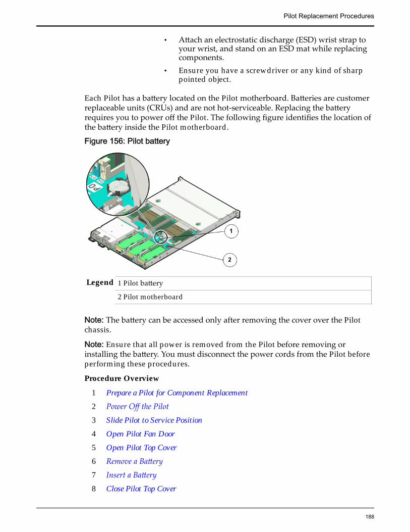
• Attach an electrostatic discharge (ESD) wrist strap toyour wrist, and stand on an ESD mat while replacingcomponents.
• Ensure you have a screwdriver or any kind of sharppointed object.
Each Pilot has a battery located on the Pilot motherboard. Batteries are customerreplaceable units (CRUs) and are not hot-serviceable. Replacing the batteryrequires you to power off the Pilot. The following figure identifies the location ofthe battery inside the Pilot motherboard.
Figure 156: Pilot battery
Legend 1 Pilot battery
2 Pilot motherboard
Note: The battery can be accessed only after removing the cover over the Pilotchassis.
Note: Ensure that all power is removed from the Pilot before removing orinstalling the battery. You must disconnect the power cords from the Pilot beforeperforming these procedures.
Procedure Overview
1 Prepare a Pilot for Component Replacement
2 Power Off the Pilot
3 Slide Pilot to Service Position
4 Open Pilot Fan Door
5 Open Pilot Top Cover
6 Remove a Battery
7 Insert a Battery
8 Close Pilot Top Cover
Pilot Replacement Procedures
188

9 Close Pilot Fan Door
10 Slide Pilot to Rack Position
11 Connect Power Cords On the Pilot
12 Verify Component Replacement on the Standby Pilot
13 Verify Component Replacement on the Active Pilot
Prepare a Pilot for Component Replacement1 Contact Oracle Customer Support prior to replacing a Pilot component.
Oracle Customer Support identifies the failed component on the Pilot foryou.
2 From Oracle FS System Manager (GUI), navigate to System > Hardware >Pilots and select the Pilot that contains the component that you want toreplace.
3 Select Actions > Repair Pilot.Guided Maintenance displays the list of Pilot components.
4 Based on the information from your Oracle Customer Supportrepresentative, select the correct component from the list.
5 Click Next.Guided Maintenance sends a request to flash the white locate LED on thePilot to help you identify the Pilot in the data center.
6 Click Next.
Guided Maintenance displays a link to Pilot Repair Procedures.7 Click the Pilot Repair Procedures link to open and print the procedures.8 Click Next.
• If you are replacing a component located on the active Pilot, GuidedMaintenance brings the active Pilot offline and fails over to thestandby Pilot. After the active Pilot is offline, the GUI closes. You cansafely disconnect the power cords and data cables. When the failoveris complete, you can log back into the GUI.
• If you are replacing a component located on the standby Pilot,Guided Maintenance brings the standby Pilot offline. After thestandby Pilot is offline, you can safely disconnect the power cordsand data cables. When servicing the standby Pilot, failover is notrequired.
• If you are replacing a power supply or a fan module, you are notrequired to bring the Pilot offline. The power supplies and fanmodules are hot-serviceable.
Note: You can replace one power supply without bringing the Pilotoffline, as long as the second power supply remains online andoperational.
Pilot Replacement Procedures
189

Power Off the Pilot
Note: Do not power off the Pilot host without ensuring that SSH is enabled onthe Oracle FS System. Otherwise, the replacement procedure might fail.
1 Notify affected users that the Pilot will be powered off.
2 Ensure that the host of the Pilot on which the replacement procedure mustbe performed is powered off.
Slide Pilot to Service Position
1 Slide the Pilot chassis fully forward until the slide rails lock into position.
Figure 157: Pilot position during component replacement
Legend 1 Rack
2 Pilot chassis
3 Pilot rails
2 When Guided Maintenance prompts you to remove the component, pullthe flip handles at front of the Pilot and start sliding the Pilot out of therack.
CAUTION: Deploy any rack anti-tilt mechanism before releasing therelease buttons and extending the Pilot.
Pilot Replacement Procedures
190

Figure 158: Pilot slide lockout release tabs
Legend 1 Slide rail lock
2 Slide lockout release tab
Note: The slide-rail locks are located behind the flip-down handles on thefront of the Pilot chassis. The slide-rail locks are released when the flip-down handles are pulled down. The slide lockout release tab must bereleased to push the Pilot chassis back into the rack.
Open Pilot Fan Door
Press the two fan door release tabs simultaneously forward and swing thePilot fan door to the open position.
Note: Servicing the Pilot fan modules and other components located in thefront of the Pilot, such as the front indication module (FIM) and the diskbackplanes, require that the fan door be opened. It is also easier to removethe Pilot’s top cover if you open the fan door first.
Pilot Replacement Procedures
191

Figure 159: Pilot with fan door open
Legend 1 Fan door release tabs
2 Pilot fan door in open position
Open Pilot Top Cover
1 Press down on the push button on the Pilot top cover to release the topcover and use the recessed areas to slide the top cover toward the back ofthe Pilot about 0.5 inches (12.7 mm).
CAUTION: Before removing the top cover of the Pilot, power off the Pilotusing Guided Maintenance. Removing the Pilot top cover before poweringoff the Pilot might cause damage to the software image on the Pilot.
Tip: Slide out the Pilot top cover by pressing down on the grooves locatedon both sides of the cover.
Figure 160: Pilot top cover removal
Legend 1 Push button to release top cover
2 Grooves to slide out top cover
2 Lift the cover off the Pilot chassis and set it aside.
Pilot Replacement Procedures
192
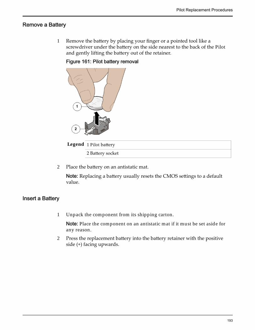
Remove a Battery
1 Remove the battery by placing your finger or a pointed tool like ascrewdriver under the battery on the side nearest to the back of the Pilotand gently lifting the battery out of the retainer.
Figure 161: Pilot battery removal
Legend 1 Pilot battery
2 Battery socket
2 Place the battery on an antistatic mat.
Note: Replacing a battery usually resets the CMOS settings to a defaultvalue.
Insert a Battery
1 Unpack the component from its shipping carton.
Note: Place the component on an antistatic mat if it must be set aside forany reason.
2 Press the replacement battery into the battery retainer with the positiveside (+) facing upwards.
Pilot Replacement Procedures
193
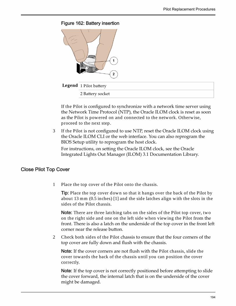
Figure 162: Battery insertion
Legend 1 Pilot battery
2 Battery socket
If the Pilot is configured to synchronize with a network time server usingthe Network Time Protocol (NTP), the Oracle ILOM clock is reset as soonas the Pilot is powered on and connected to the network. Otherwise,proceed to the next step.
3 If the Pilot is not configured to use NTP, reset the Oracle ILOM clock usingthe Oracle ILOM CLI or the web interface. You can also reprogram theBIOS Setup utility to reprogram the host clock.For instructions, on setting the Oracle ILOM clock, see the OracleIntegrated Lights Out Manager (ILOM) 3.1 Documentation Library.
Close Pilot Top Cover
1 Place the top cover of the Pilot onto the chassis.
Tip: Place the top cover down so that it hangs over the back of the Pilot byabout 13 mm (0.5 inches) [1] and the side latches align with the slots in thesides of the Pilot chassis.
Note: There are three latching tabs on the sides of the Pilot top cover, twoon the right side and one on the left side when viewing the Pilot from thefront. There is also a latch on the underside of the top cover in the front leftcorner near the release button.
2 Check both sides of the Pilot chassis to ensure that the four corners of thetop cover are fully down and flush with the chassis.
Note: If the cover corners are not flush with the Pilot chassis, slide thecover towards the back of the chassis until you can position the covercorrectly.
Note: If the top cover is not correctly positioned before attempting to slidethe cover forward, the internal latch that is on the underside of the covermight be damaged.
Pilot Replacement Procedures
194
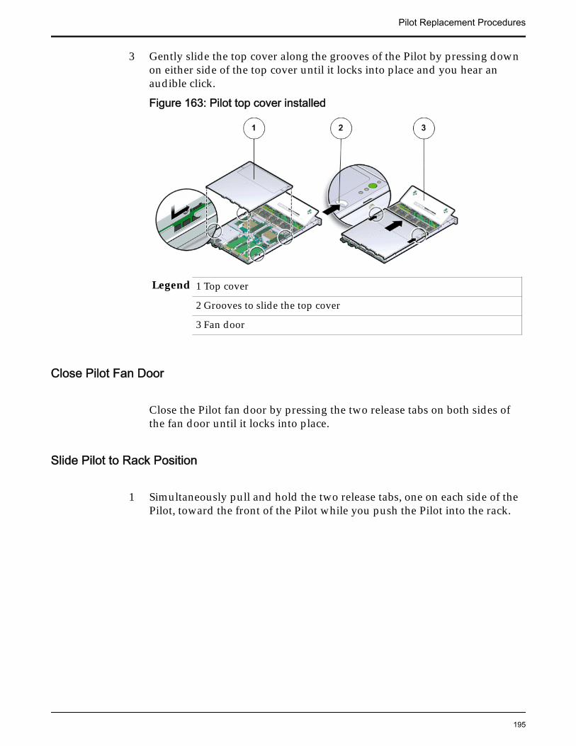
3 Gently slide the top cover along the grooves of the Pilot by pressing downon either side of the top cover until it locks into place and you hear anaudible click.
Figure 163: Pilot top cover installed
Legend 1 Top cover
2 Grooves to slide the top cover
3 Fan door
Close Pilot Fan Door
Close the Pilot fan door by pressing the two release tabs on both sides ofthe fan door until it locks into place.
Slide Pilot to Rack Position
1 Simultaneously pull and hold the two release tabs, one on each side of thePilot, toward the front of the Pilot while you push the Pilot into the rack.
Pilot Replacement Procedures
195

Figure 164: Location of the Pilot release tabs
Note: As you push the Pilot into the rack, verify that the cable managementarm (CMA) retracts without binding.
Note: To pull the Pilot release tab, place your finger in the center of the tab,not on the end, and apply pressure as you pull the tab toward the front ofthe Pilot.
2 Continue pushing the Pilot into the rack until the slide-rail locks on thefront of the Pilot engage the slide-rail assemblies.
Note: The Pilot locks into the rack position with an audible click.
Connect Power Cords On the Pilot
Reconnect the power cords to the Pilot.
Note: After the power cords are connected, the green SP LED and the OKLED both start to blink.
Note: Do not turn on the power to the Pilot host immediately. The poweron the Pilot host is turned on only after updating the Pilot BIOS. Turningon the power to the Pilot host early can prevent the Pilot from booting afterthe Pilot BIOS is updated.
Verify Component Replacement on the Standby PilotIf you replaced a component on the standby Pilot, complete the following stepsto verify the status of the Pilot:
1 Return to Guided Maintenance and click Finish.
Guided Maintenance closes and the GUI displays the Pilot Overview page.
2 From the Pilot Overview page, review the status of the Pilot.A status of Normal requires no action.
Pilot Replacement Procedures
196
Verify Component Replacement on the Active PilotIf you replaced a component on the active Pilot, complete the following steps toverify the status of the Pilot:
1 Restart Oracle FS System Manager (GUI).
2 Navigate to System > Hardware > Pilots.
The GUI displays the Pilot Overview page.
3 From the Pilot Overview page, review the status of the Pilot.A status of Normal requires no action.
Replace a Pilot SAS HBAA serial attached SCSI (SAS) host bus adapter (HBA) provides access to the SAShard disk drive (HDD) in the Pilot. A damaged SAS HBA can result in losingaccess to the SAS HDD to which the SAS HBA connects using the SAS cablebundle and must be replaced as soon as possible.
Prerequisites: • Before handling a component, touch a groundedsurface to discharge any static electricity.
• Attach an electrostatic discharge (ESD) wrist strap toyour wrist, and stand on an ESD mat while replacingcomponents.
• Ensure that you have a Phillips Number 2screwdriver with at least a 4-inch shaft.
• Use only the filler panels provided with the Pilot tomaintain proper airflow and EMI conformance forempty slots inside the Pilot.
• Fail over the Pilot before replacing the componentusing Guided Maintenance
Note: The Pilot must be failed over to prevent dataloss or data corruption during the componentreplacement process.
Each Pilot supports a single 6 Gb/s SAS HBA on the PCIe slot of its riser. Toservice a SAS HBA, the PCIe risers inside the Pilot and the filler panels inside theriser must be removed. The SAS HBA is a customer replaceable unit (CRU) and isnot hot-serviceable. However, replacing a SAS HBA will require failing over alloperations to the other Pilot. The following figure shows the location of the SASHBA inside a riser board assembly.
Pilot Replacement Procedures
197
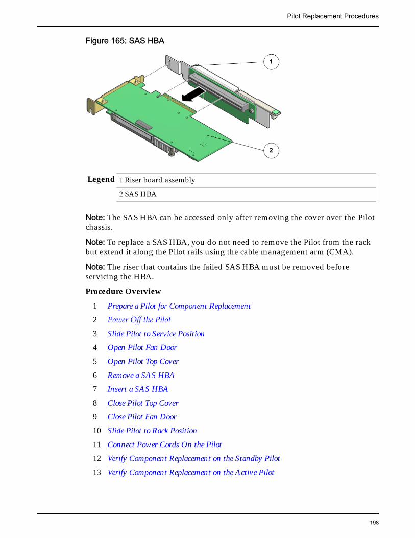
Figure 165: SAS HBA
Legend 1 Riser board assembly
2 SAS HBA
Note: The SAS HBA can be accessed only after removing the cover over the Pilotchassis.
Note: To replace a SAS HBA, you do not need to remove the Pilot from the rackbut extend it along the Pilot rails using the cable management arm (CMA).
Note: The riser that contains the failed SAS HBA must be removed beforeservicing the HBA.
Procedure Overview
1 Prepare a Pilot for Component Replacement
2 Power Off the Pilot
3 Slide Pilot to Service Position
4 Open Pilot Fan Door
5 Open Pilot Top Cover
6 Remove a SAS HBA
7 Insert a SAS HBA
8 Close Pilot Top Cover
9 Close Pilot Fan Door
10 Slide Pilot to Rack Position
11 Connect Power Cords On the Pilot
12 Verify Component Replacement on the Standby Pilot
13 Verify Component Replacement on the Active Pilot
Pilot Replacement Procedures
198
Prepare a Pilot for Component Replacement1 Contact Oracle Customer Support prior to replacing a Pilot component.
Oracle Customer Support identifies the failed component on the Pilot foryou.
2 From Oracle FS System Manager (GUI), navigate to System > Hardware >Pilots and select the Pilot that contains the component that you want toreplace.
3 Select Actions > Repair Pilot.Guided Maintenance displays the list of Pilot components.
4 Based on the information from your Oracle Customer Supportrepresentative, select the correct component from the list.
5 Click Next.Guided Maintenance sends a request to flash the white locate LED on thePilot to help you identify the Pilot in the data center.
6 Click Next.
Guided Maintenance displays a link to Pilot Repair Procedures.
7 Click the Pilot Repair Procedures link to open and print the procedures.
8 Click Next.
• If you are replacing a component located on the active Pilot, GuidedMaintenance brings the active Pilot offline and fails over to thestandby Pilot. After the active Pilot is offline, the GUI closes. You cansafely disconnect the power cords and data cables. When the failoveris complete, you can log back into the GUI.
• If you are replacing a component located on the standby Pilot,Guided Maintenance brings the standby Pilot offline. After thestandby Pilot is offline, you can safely disconnect the power cordsand data cables. When servicing the standby Pilot, failover is notrequired.
• If you are replacing a power supply or a fan module, you are notrequired to bring the Pilot offline. The power supplies and fanmodules are hot-serviceable.
Note: You can replace one power supply without bringing the Pilotoffline, as long as the second power supply remains online andoperational.
Power Off the Pilot
Note: Do not power off the Pilot host without ensuring that SSH is enabled onthe Oracle FS System. Otherwise, the replacement procedure might fail.
1 Notify affected users that the Pilot will be powered off.
Pilot Replacement Procedures
199
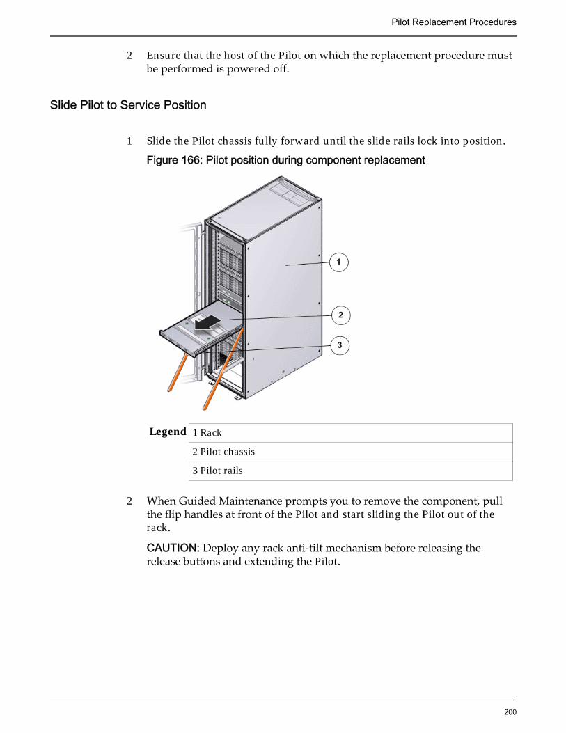
2 Ensure that the host of the Pilot on which the replacement procedure mustbe performed is powered off.
Slide Pilot to Service Position
1 Slide the Pilot chassis fully forward until the slide rails lock into position.
Figure 166: Pilot position during component replacement
Legend 1 Rack
2 Pilot chassis
3 Pilot rails
2 When Guided Maintenance prompts you to remove the component, pullthe flip handles at front of the Pilot and start sliding the Pilot out of therack.
CAUTION: Deploy any rack anti-tilt mechanism before releasing therelease buttons and extending the Pilot.
Pilot Replacement Procedures
200
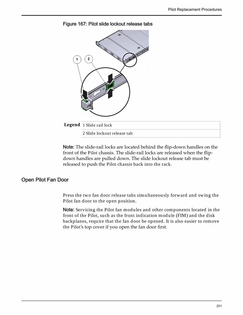
Figure 167: Pilot slide lockout release tabs
Legend 1 Slide rail lock
2 Slide lockout release tab
Note: The slide-rail locks are located behind the flip-down handles on thefront of the Pilot chassis. The slide-rail locks are released when the flip-down handles are pulled down. The slide lockout release tab must bereleased to push the Pilot chassis back into the rack.
Open Pilot Fan Door
Press the two fan door release tabs simultaneously forward and swing thePilot fan door to the open position.
Note: Servicing the Pilot fan modules and other components located in thefront of the Pilot, such as the front indication module (FIM) and the diskbackplanes, require that the fan door be opened. It is also easier to removethe Pilot’s top cover if you open the fan door first.
Pilot Replacement Procedures
201
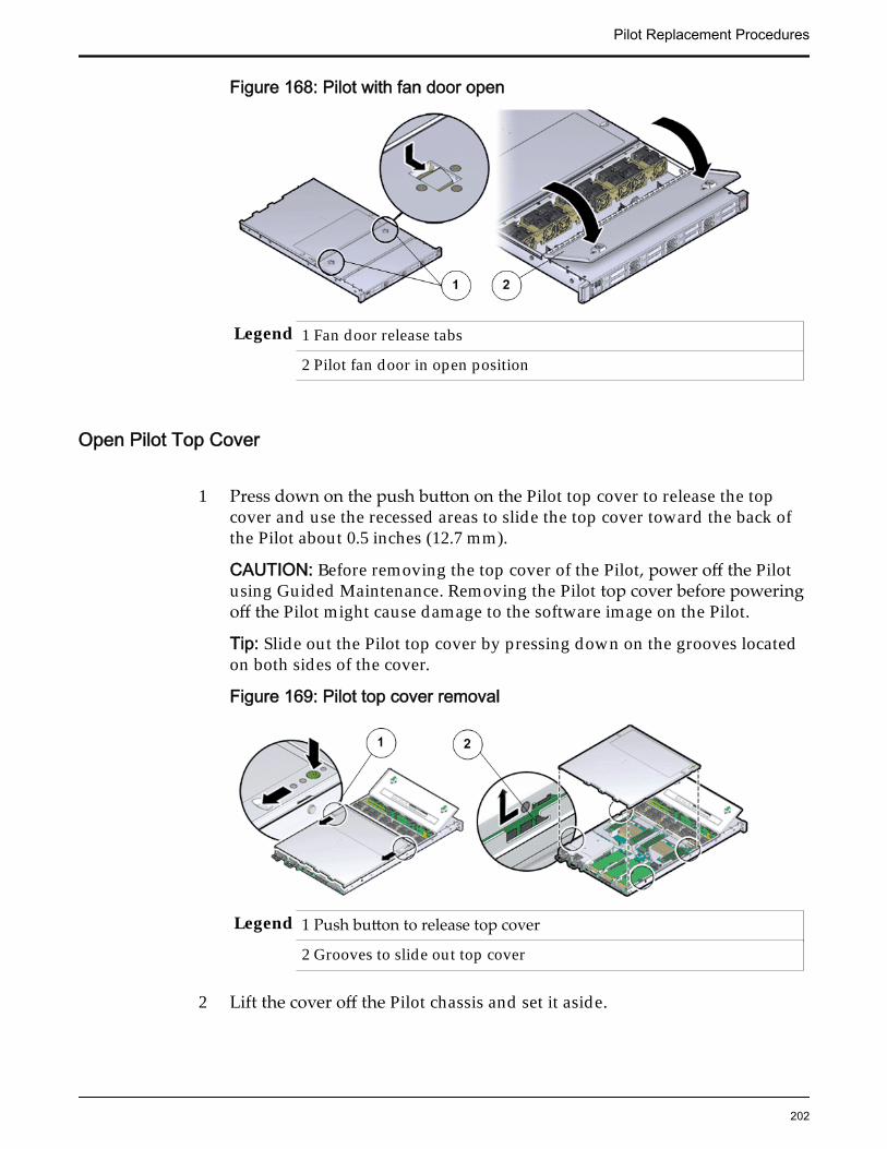
Figure 168: Pilot with fan door open
Legend 1 Fan door release tabs
2 Pilot fan door in open position
Open Pilot Top Cover
1 Press down on the push button on the Pilot top cover to release the topcover and use the recessed areas to slide the top cover toward the back ofthe Pilot about 0.5 inches (12.7 mm).
CAUTION: Before removing the top cover of the Pilot, power off the Pilotusing Guided Maintenance. Removing the Pilot top cover before poweringoff the Pilot might cause damage to the software image on the Pilot.
Tip: Slide out the Pilot top cover by pressing down on the grooves locatedon both sides of the cover.
Figure 169: Pilot top cover removal
Legend 1 Push button to release top cover
2 Grooves to slide out top cover
2 Lift the cover off the Pilot chassis and set it aside.
Pilot Replacement Procedures
202
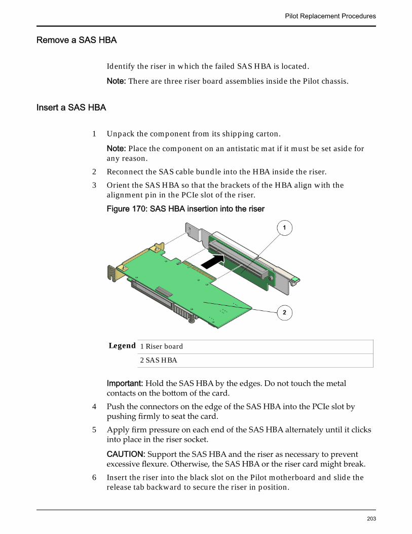
Remove a SAS HBA
Identify the riser in which the failed SAS HBA is located.
Note: There are three riser board assemblies inside the Pilot chassis.
Insert a SAS HBA
1 Unpack the component from its shipping carton.
Note: Place the component on an antistatic mat if it must be set aside forany reason.
2 Reconnect the SAS cable bundle into the HBA inside the riser.3 Orient the SAS HBA so that the brackets of the HBA align with the
alignment pin in the PCIe slot of the riser.
Figure 170: SAS HBA insertion into the riser
Legend 1 Riser board
2 SAS HBA
Important: Hold the SAS HBA by the edges. Do not touch the metalcontacts on the bottom of the card.
4 Push the connectors on the edge of the SAS HBA into the PCIe slot bypushing firmly to seat the card.
5 Apply firm pressure on each end of the SAS HBA alternately until it clicksinto place in the riser socket.
CAUTION: Support the SAS HBA and the riser as necessary to preventexcessive flexure. Otherwise, the SAS HBA or the riser card might break.
6 Insert the riser into the black slot on the Pilot motherboard and slide therelease tab backward to secure the riser in position.
Pilot Replacement Procedures
203
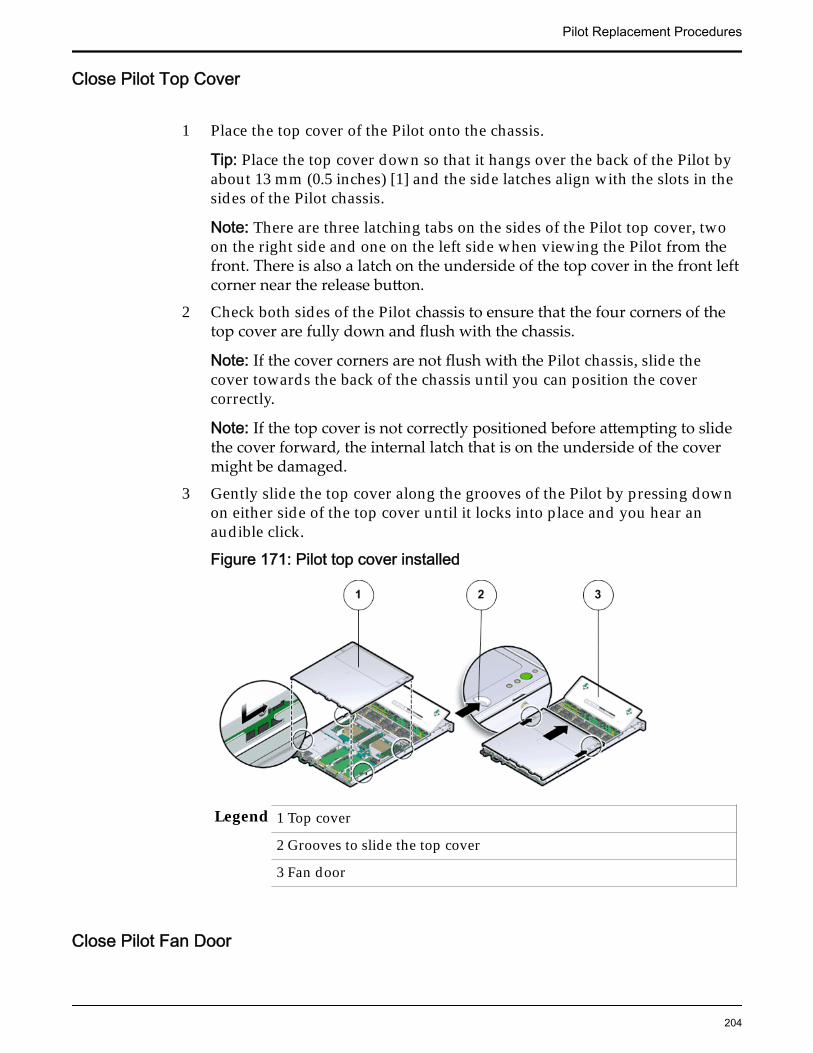
Close Pilot Top Cover
1 Place the top cover of the Pilot onto the chassis.
Tip: Place the top cover down so that it hangs over the back of the Pilot byabout 13 mm (0.5 inches) [1] and the side latches align with the slots in thesides of the Pilot chassis.
Note: There are three latching tabs on the sides of the Pilot top cover, twoon the right side and one on the left side when viewing the Pilot from thefront. There is also a latch on the underside of the top cover in the front leftcorner near the release button.
2 Check both sides of the Pilot chassis to ensure that the four corners of thetop cover are fully down and flush with the chassis.
Note: If the cover corners are not flush with the Pilot chassis, slide thecover towards the back of the chassis until you can position the covercorrectly.
Note: If the top cover is not correctly positioned before attempting to slidethe cover forward, the internal latch that is on the underside of the covermight be damaged.
3 Gently slide the top cover along the grooves of the Pilot by pressing downon either side of the top cover until it locks into place and you hear anaudible click.
Figure 171: Pilot top cover installed
Legend 1 Top cover
2 Grooves to slide the top cover
3 Fan door
Close Pilot Fan Door
Pilot Replacement Procedures
204
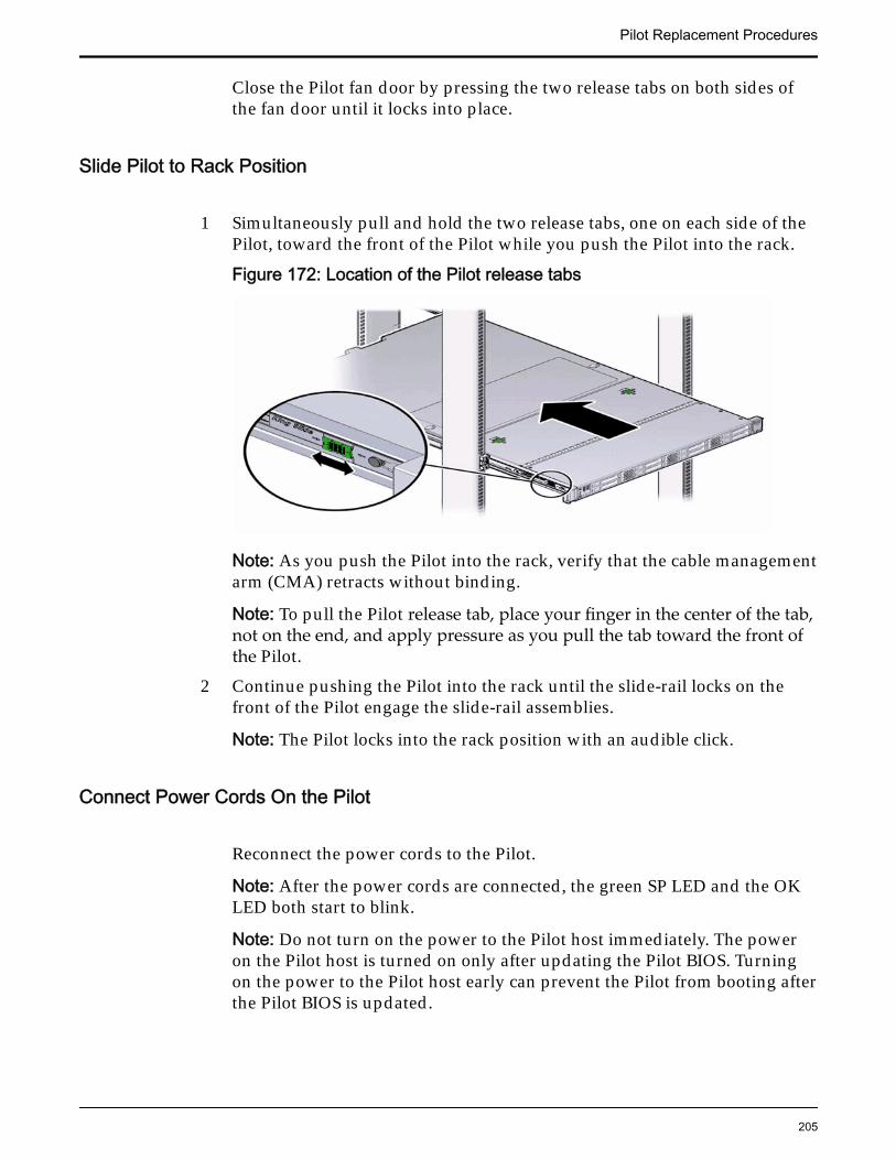
Close the Pilot fan door by pressing the two release tabs on both sides ofthe fan door until it locks into place.
Slide Pilot to Rack Position
1 Simultaneously pull and hold the two release tabs, one on each side of thePilot, toward the front of the Pilot while you push the Pilot into the rack.
Figure 172: Location of the Pilot release tabs
Note: As you push the Pilot into the rack, verify that the cable managementarm (CMA) retracts without binding.
Note: To pull the Pilot release tab, place your finger in the center of the tab,not on the end, and apply pressure as you pull the tab toward the front ofthe Pilot.
2 Continue pushing the Pilot into the rack until the slide-rail locks on thefront of the Pilot engage the slide-rail assemblies.
Note: The Pilot locks into the rack position with an audible click.
Connect Power Cords On the Pilot
Reconnect the power cords to the Pilot.
Note: After the power cords are connected, the green SP LED and the OKLED both start to blink.
Note: Do not turn on the power to the Pilot host immediately. The poweron the Pilot host is turned on only after updating the Pilot BIOS. Turningon the power to the Pilot host early can prevent the Pilot from booting afterthe Pilot BIOS is updated.
Pilot Replacement Procedures
205
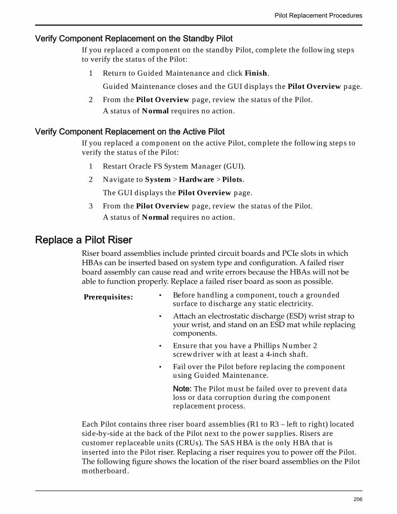
Verify Component Replacement on the Standby PilotIf you replaced a component on the standby Pilot, complete the following stepsto verify the status of the Pilot:
1 Return to Guided Maintenance and click Finish.
Guided Maintenance closes and the GUI displays the Pilot Overview page.
2 From the Pilot Overview page, review the status of the Pilot.A status of Normal requires no action.
Verify Component Replacement on the Active PilotIf you replaced a component on the active Pilot, complete the following steps toverify the status of the Pilot:
1 Restart Oracle FS System Manager (GUI).
2 Navigate to System > Hardware > Pilots.
The GUI displays the Pilot Overview page.
3 From the Pilot Overview page, review the status of the Pilot.A status of Normal requires no action.
Replace a Pilot RiserRiser board assemblies include printed circuit boards and PCIe slots in whichHBAs can be inserted based on system type and configuration. A failed riserboard assembly can cause read and write errors because the HBAs will not beable to function properly. Replace a failed riser board as soon as possible.
Prerequisites: • Before handling a component, touch a groundedsurface to discharge any static electricity.
• Attach an electrostatic discharge (ESD) wrist strap toyour wrist, and stand on an ESD mat while replacingcomponents.
• Ensure that you have a Phillips Number 2screwdriver with at least a 4-inch shaft.
• Fail over the Pilot before replacing the componentusing Guided Maintenance.
Note: The Pilot must be failed over to prevent dataloss or data corruption during the componentreplacement process.
Each Pilot contains three riser board assemblies (R1 to R3 – left to right) locatedside-by-side at the back of the Pilot next to the power supplies. Risers arecustomer replaceable units (CRUs). The SAS HBA is the only HBA that isinserted into the Pilot riser. Replacing a riser requires you to power off the Pilot.The following figure shows the location of the riser board assemblies on the Pilotmotherboard.
Pilot Replacement Procedures
206
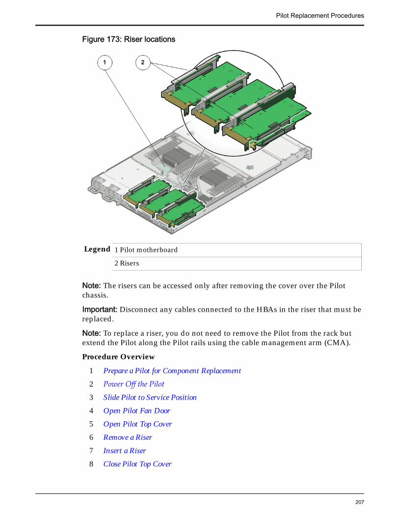
Figure 173: Riser locations
Legend 1 Pilot motherboard
2 Risers
Note: The risers can be accessed only after removing the cover over the Pilotchassis.
Important: Disconnect any cables connected to the HBAs in the riser that must bereplaced.
Note: To replace a riser, you do not need to remove the Pilot from the rack butextend the Pilot along the Pilot rails using the cable management arm (CMA).
Procedure Overview
1 Prepare a Pilot for Component Replacement
2 Power Off the Pilot
3 Slide Pilot to Service Position
4 Open Pilot Fan Door
5 Open Pilot Top Cover
6 Remove a Riser
7 Insert a Riser
8 Close Pilot Top Cover
Pilot Replacement Procedures
207
9 Close Pilot Fan Door
10 Slide Pilot to Rack Position
11 Connect Power Cords On the Pilot
12 Verify Component Replacement on the Standby Pilot
13 Verify Component Replacement on the Active Pilot
Prepare a Pilot for Component Replacement1 Contact Oracle Customer Support prior to replacing a Pilot component.
Oracle Customer Support identifies the failed component on the Pilot foryou.
2 From Oracle FS System Manager (GUI), navigate to System > Hardware >Pilots and select the Pilot that contains the component that you want toreplace.
3 Select Actions > Repair Pilot.Guided Maintenance displays the list of Pilot components.
4 Based on the information from your Oracle Customer Supportrepresentative, select the correct component from the list.
5 Click Next.Guided Maintenance sends a request to flash the white locate LED on thePilot to help you identify the Pilot in the data center.
6 Click Next.
Guided Maintenance displays a link to Pilot Repair Procedures.7 Click the Pilot Repair Procedures link to open and print the procedures.8 Click Next.
• If you are replacing a component located on the active Pilot, GuidedMaintenance brings the active Pilot offline and fails over to thestandby Pilot. After the active Pilot is offline, the GUI closes. You cansafely disconnect the power cords and data cables. When the failoveris complete, you can log back into the GUI.
• If you are replacing a component located on the standby Pilot,Guided Maintenance brings the standby Pilot offline. After thestandby Pilot is offline, you can safely disconnect the power cordsand data cables. When servicing the standby Pilot, failover is notrequired.
• If you are replacing a power supply or a fan module, you are notrequired to bring the Pilot offline. The power supplies and fanmodules are hot-serviceable.
Note: You can replace one power supply without bringing the Pilotoffline, as long as the second power supply remains online andoperational.
Pilot Replacement Procedures
208
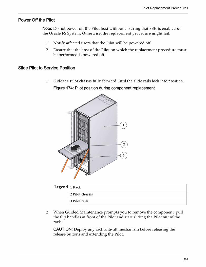
Power Off the Pilot
Note: Do not power off the Pilot host without ensuring that SSH is enabled onthe Oracle FS System. Otherwise, the replacement procedure might fail.
1 Notify affected users that the Pilot will be powered off.
2 Ensure that the host of the Pilot on which the replacement procedure mustbe performed is powered off.
Slide Pilot to Service Position
1 Slide the Pilot chassis fully forward until the slide rails lock into position.
Figure 174: Pilot position during component replacement
Legend 1 Rack
2 Pilot chassis
3 Pilot rails
2 When Guided Maintenance prompts you to remove the component, pullthe flip handles at front of the Pilot and start sliding the Pilot out of therack.
CAUTION: Deploy any rack anti-tilt mechanism before releasing therelease buttons and extending the Pilot.
Pilot Replacement Procedures
209

Figure 175: Pilot slide lockout release tabs
Legend 1 Slide rail lock
2 Slide lockout release tab
Note: The slide-rail locks are located behind the flip-down handles on thefront of the Pilot chassis. The slide-rail locks are released when the flip-down handles are pulled down. The slide lockout release tab must bereleased to push the Pilot chassis back into the rack.
Open Pilot Fan Door
Press the two fan door release tabs simultaneously forward and swing thePilot fan door to the open position.
Note: Servicing the Pilot fan modules and other components located in thefront of the Pilot, such as the front indication module (FIM) and the diskbackplanes, require that the fan door be opened. It is also easier to removethe Pilot’s top cover if you open the fan door first.
Pilot Replacement Procedures
210

Figure 176: Pilot with fan door open
Legend 1 Fan door release tabs
2 Pilot fan door in open position
Open Pilot Top Cover
1 Press down on the push button on the Pilot top cover to release the topcover and use the recessed areas to slide the top cover toward the back ofthe Pilot about 0.5 inches (12.7 mm).
CAUTION: Before removing the top cover of the Pilot, power off the Pilotusing Guided Maintenance. Removing the Pilot top cover before poweringoff the Pilot might cause damage to the software image on the Pilot.
Tip: Slide out the Pilot top cover by pressing down on the grooves locatedon both sides of the cover.
Figure 177: Pilot top cover removal
Legend 1 Push button to release top cover
2 Grooves to slide out top cover
2 Lift the cover off the Pilot chassis and set it aside.
Pilot Replacement Procedures
211
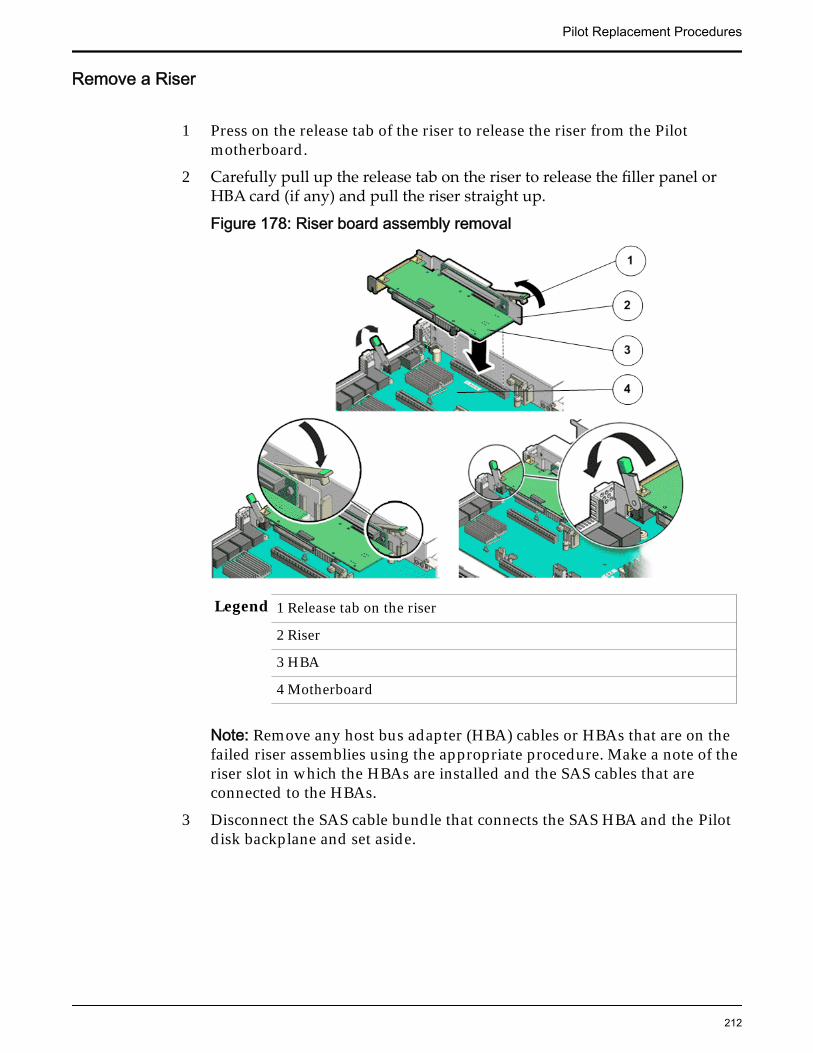
Remove a Riser
1 Press on the release tab of the riser to release the riser from the Pilotmotherboard.
2 Carefully pull up the release tab on the riser to release the filler panel orHBA card (if any) and pull the riser straight up.
Figure 178: Riser board assembly removal
Legend 1 Release tab on the riser
2 Riser
3 HBA
4 Motherboard
Note: Remove any host bus adapter (HBA) cables or HBAs that are on thefailed riser assemblies using the appropriate procedure. Make a note of theriser slot in which the HBAs are installed and the SAS cables that areconnected to the HBAs.
3 Disconnect the SAS cable bundle that connects the SAS HBA and the Pilotdisk backplane and set aside.
Pilot Replacement Procedures
212
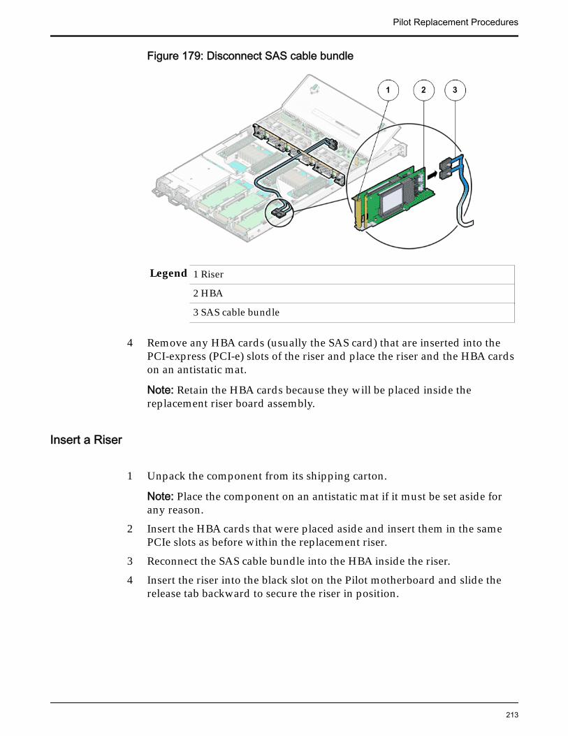
Figure 179: Disconnect SAS cable bundle
Legend 1 Riser
2 HBA
3 SAS cable bundle
4 Remove any HBA cards (usually the SAS card) that are inserted into thePCI-express (PCI-e) slots of the riser and place the riser and the HBA cardson an antistatic mat.
Note: Retain the HBA cards because they will be placed inside thereplacement riser board assembly.
Insert a Riser
1 Unpack the component from its shipping carton.
Note: Place the component on an antistatic mat if it must be set aside forany reason.
2 Insert the HBA cards that were placed aside and insert them in the samePCIe slots as before within the replacement riser.
3 Reconnect the SAS cable bundle into the HBA inside the riser.
4 Insert the riser into the black slot on the Pilot motherboard and slide therelease tab backward to secure the riser in position.
Pilot Replacement Procedures
213
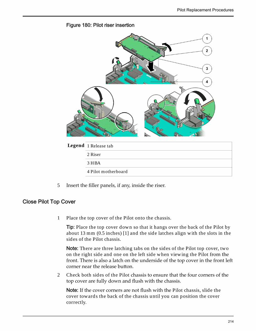
Figure 180: Pilot riser insertion
Legend 1 Release tab
2 Riser
3 HBA
4 Pilot motherboard
5 Insert the filler panels, if any, inside the riser.
Close Pilot Top Cover
1 Place the top cover of the Pilot onto the chassis.
Tip: Place the top cover down so that it hangs over the back of the Pilot byabout 13 mm (0.5 inches) [1] and the side latches align with the slots in thesides of the Pilot chassis.
Note: There are three latching tabs on the sides of the Pilot top cover, twoon the right side and one on the left side when viewing the Pilot from thefront. There is also a latch on the underside of the top cover in the front leftcorner near the release button.
2 Check both sides of the Pilot chassis to ensure that the four corners of thetop cover are fully down and flush with the chassis.
Note: If the cover corners are not flush with the Pilot chassis, slide thecover towards the back of the chassis until you can position the covercorrectly.
Pilot Replacement Procedures
214

Note: If the top cover is not correctly positioned before attempting to slidethe cover forward, the internal latch that is on the underside of the covermight be damaged.
3 Gently slide the top cover along the grooves of the Pilot by pressing downon either side of the top cover until it locks into place and you hear anaudible click.
Figure 181: Pilot top cover installed
Legend 1 Top cover
2 Grooves to slide the top cover
3 Fan door
Close Pilot Fan Door
Close the Pilot fan door by pressing the two release tabs on both sides ofthe fan door until it locks into place.
Slide Pilot to Rack Position
1 Simultaneously pull and hold the two release tabs, one on each side of thePilot, toward the front of the Pilot while you push the Pilot into the rack.
Pilot Replacement Procedures
215
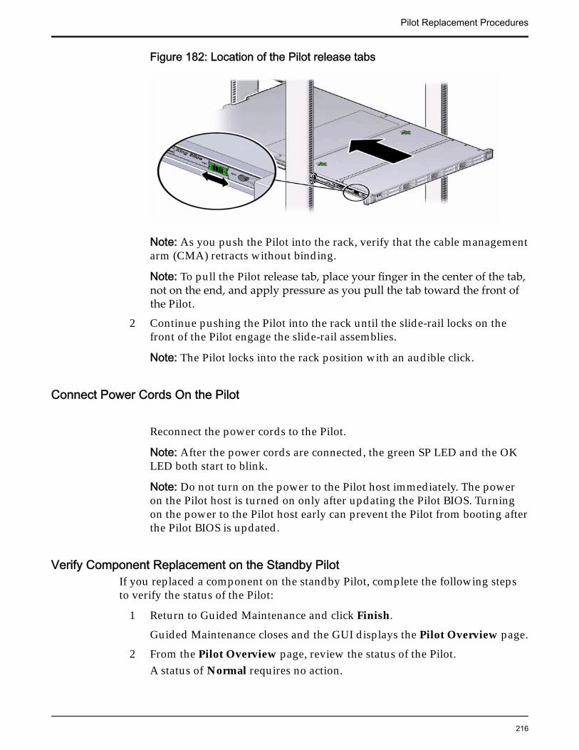
Figure 182: Location of the Pilot release tabs
Note: As you push the Pilot into the rack, verify that the cable managementarm (CMA) retracts without binding.
Note: To pull the Pilot release tab, place your finger in the center of the tab,not on the end, and apply pressure as you pull the tab toward the front ofthe Pilot.
2 Continue pushing the Pilot into the rack until the slide-rail locks on thefront of the Pilot engage the slide-rail assemblies.
Note: The Pilot locks into the rack position with an audible click.
Connect Power Cords On the Pilot
Reconnect the power cords to the Pilot.
Note: After the power cords are connected, the green SP LED and the OKLED both start to blink.
Note: Do not turn on the power to the Pilot host immediately. The poweron the Pilot host is turned on only after updating the Pilot BIOS. Turningon the power to the Pilot host early can prevent the Pilot from booting afterthe Pilot BIOS is updated.
Verify Component Replacement on the Standby PilotIf you replaced a component on the standby Pilot, complete the following stepsto verify the status of the Pilot:
1 Return to Guided Maintenance and click Finish.
Guided Maintenance closes and the GUI displays the Pilot Overview page.
2 From the Pilot Overview page, review the status of the Pilot.A status of Normal requires no action.
Pilot Replacement Procedures
216
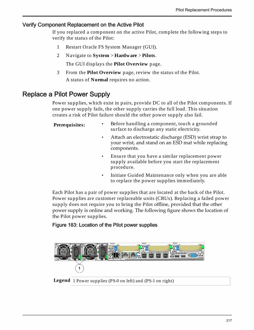
Verify Component Replacement on the Active PilotIf you replaced a component on the active Pilot, complete the following steps toverify the status of the Pilot:
1 Restart Oracle FS System Manager (GUI).
2 Navigate to System > Hardware > Pilots.
The GUI displays the Pilot Overview page.
3 From the Pilot Overview page, review the status of the Pilot.A status of Normal requires no action.
Replace a Pilot Power SupplyPower supplies, which exist in pairs, provide DC to all of the Pilot components. Ifone power supply fails, the other supply carries the full load. This situationcreates a risk of Pilot failure should the other power supply also fail.
Prerequisites: • Before handling a component, touch a groundedsurface to discharge any static electricity.
• Attach an electrostatic discharge (ESD) wrist strap toyour wrist, and stand on an ESD mat while replacingcomponents.
• Ensure that you have a similar replacement powersupply available before you start the replacementprocedure.
• Initiate Guided Maintenance only when you are ableto replace the power supplies immediately.
Each Pilot has a pair of power supplies that are located at the back of the Pilot.Power supplies are customer replaceable units (CRUs). Replacing a failed powersupply does not require you to bring the Pilot offline, provided that the otherpower supply is online and working. The following figure shows the location ofthe Pilot power supplies.
Figure 183: Location of the Pilot power supplies
Legend 1 Power supplies (PS-0 on left) and (PS-1 on right)
Pilot Replacement Procedures
217
Note: To replace a power supply, the left side of the CMA must be disengagedfrom the end of the slide before the power supply can be pulled out. Disengagingthe CMA reduces the risk of damaging the cables.
Important: Do not remove the failed power supply until you have a replacementpower supply to ensure proper airflow in the Pilot.
Procedure Overview
1 Prepare a Pilot for Component Replacement
2 Remove a Power Supply
3 Insert a Power Supply
4 Verify Power Supply Replacement on a Pilot
Prepare a Pilot for Component Replacement1 Contact Oracle Customer Support prior to replacing a Pilot component.
Oracle Customer Support identifies the failed component on the Pilot foryou.
2 From Oracle FS System Manager (GUI), navigate to System > Hardware >Pilots and select the Pilot that contains the component that you want toreplace.
3 Select Actions > Repair Pilot.Guided Maintenance displays the list of Pilot components.
4 Based on the information from your Oracle Customer Supportrepresentative, select the correct component from the list.
5 Click Next.Guided Maintenance sends a request to flash the white locate LED on thePilot to help you identify the Pilot in the data center.
6 Click Next.
Guided Maintenance displays a link to Pilot Repair Procedures.
7 Click the Pilot Repair Procedures link to open and print the procedures.
8 Click Next.
• If you are replacing a component located on the active Pilot, GuidedMaintenance brings the active Pilot offline and fails over to thestandby Pilot. After the active Pilot is offline, the GUI closes. You cansafely disconnect the power cords and data cables. When the failoveris complete, you can log back into the GUI.
• If you are replacing a component located on the standby Pilot,Guided Maintenance brings the standby Pilot offline. After thestandby Pilot is offline, you can safely disconnect the power cordsand data cables. When servicing the standby Pilot, failover is notrequired.
Pilot Replacement Procedures
218
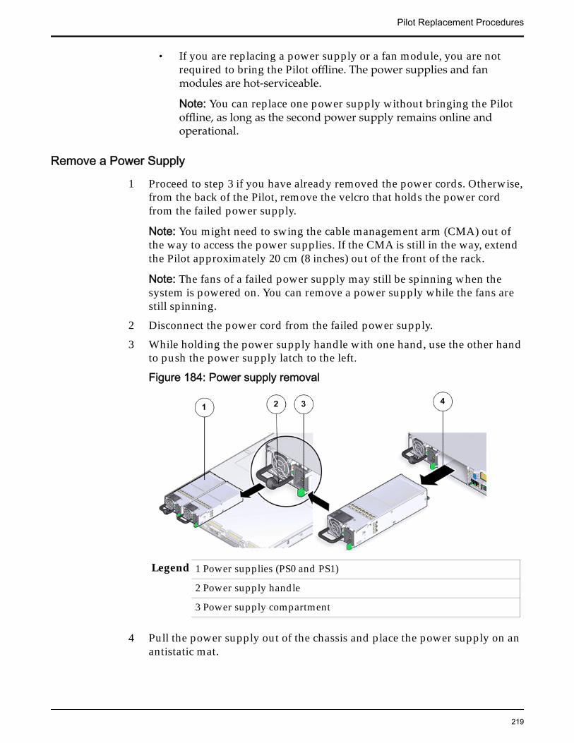
• If you are replacing a power supply or a fan module, you are notrequired to bring the Pilot offline. The power supplies and fanmodules are hot-serviceable.
Note: You can replace one power supply without bringing the Pilotoffline, as long as the second power supply remains online andoperational.
Remove a Power Supply
1 Proceed to step 3 if you have already removed the power cords. Otherwise,from the back of the Pilot, remove the velcro that holds the power cordfrom the failed power supply.
Note: You might need to swing the cable management arm (CMA) out ofthe way to access the power supplies. If the CMA is still in the way, extendthe Pilot approximately 20 cm (8 inches) out of the front of the rack.
Note: The fans of a failed power supply may still be spinning when thesystem is powered on. You can remove a power supply while the fans arestill spinning.
2 Disconnect the power cord from the failed power supply.
3 While holding the power supply handle with one hand, use the other handto push the power supply latch to the left.
Figure 184: Power supply removal
Legend 1 Power supplies (PS0 and PS1)
2 Power supply handle
3 Power supply compartment
4 Pull the power supply out of the chassis and place the power supply on anantistatic mat.
Pilot Replacement Procedures
219
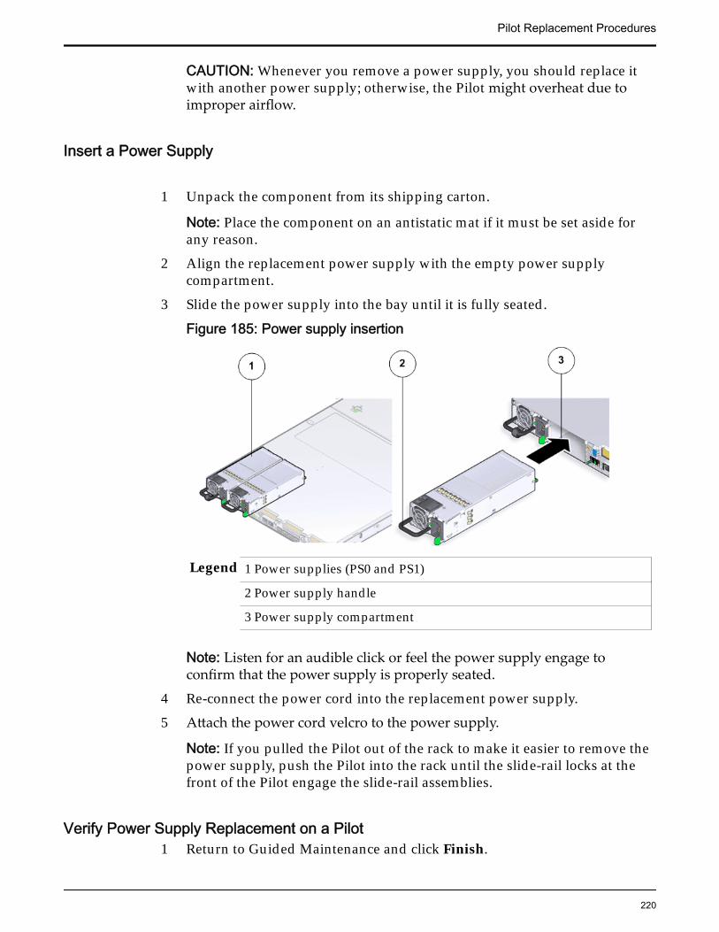
CAUTION: Whenever you remove a power supply, you should replace itwith another power supply; otherwise, the Pilot might overheat due toimproper airflow.
Insert a Power Supply
1 Unpack the component from its shipping carton.
Note: Place the component on an antistatic mat if it must be set aside forany reason.
2 Align the replacement power supply with the empty power supplycompartment.
3 Slide the power supply into the bay until it is fully seated.
Figure 185: Power supply insertion
Legend 1 Power supplies (PS0 and PS1)
2 Power supply handle
3 Power supply compartment
Note: Listen for an audible click or feel the power supply engage toconfirm that the power supply is properly seated.
4 Re-connect the power cord into the replacement power supply.
5 Attach the power cord velcro to the power supply.
Note: If you pulled the Pilot out of the rack to make it easier to remove thepower supply, push the Pilot into the rack until the slide-rail locks at thefront of the Pilot engage the slide-rail assemblies.
Verify Power Supply Replacement on a Pilot1 Return to Guided Maintenance and click Finish.
Pilot Replacement Procedures
220
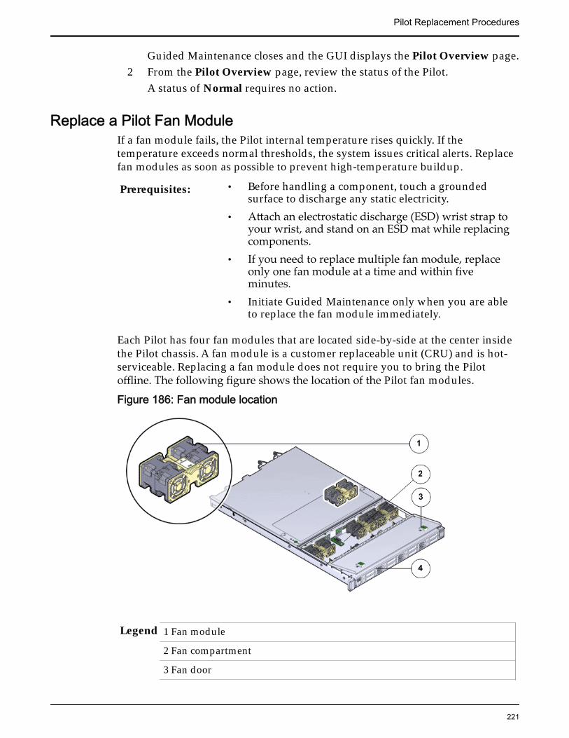
Guided Maintenance closes and the GUI displays the Pilot Overview page.2 From the Pilot Overview page, review the status of the Pilot.
A status of Normal requires no action.
Replace a Pilot Fan ModuleIf a fan module fails, the Pilot internal temperature rises quickly. If thetemperature exceeds normal thresholds, the system issues critical alerts. Replacefan modules as soon as possible to prevent high-temperature buildup.
Prerequisites: • Before handling a component, touch a groundedsurface to discharge any static electricity.
• Attach an electrostatic discharge (ESD) wrist strap toyour wrist, and stand on an ESD mat while replacingcomponents.
• If you need to replace multiple fan module, replaceonly one fan module at a time and within fiveminutes.
• Initiate Guided Maintenance only when you are ableto replace the fan module immediately.
Each Pilot has four fan modules that are located side-by-side at the center insidethe Pilot chassis. A fan module is a customer replaceable unit (CRU) and is hot-serviceable. Replacing a fan module does not require you to bring the Pilotoffline. The following figure shows the location of the Pilot fan modules.
Figure 186: Fan module location
Legend 1 Fan module
2 Fan compartment
3 Fan door
Pilot Replacement Procedures
221
4 Pilot
Note: The fan module can be accessed only after removing the cover over thePilot chassis.
Note: To replace a fan module, you do not need to remove the Pilot from the rackbut extend it along the Pilot rails using the cable management arm (CMA).
Procedure Overview
1 Prepare a Pilot for Component Replacement
2 Slide Pilot to Service Position
3 Open Pilot Fan Door
4 Remove a Fan Module
5 Insert a Fan Module
6 Close Pilot Fan Door
7 Slide Pilot to Rack Position
8 Verify Component Replacement on the Standby Pilot
9 Verify Component Replacement on the Active Pilot
Prepare a Pilot for Component Replacement1 Contact Oracle Customer Support prior to replacing a Pilot component.
Oracle Customer Support identifies the failed component on the Pilot foryou.
2 From Oracle FS System Manager (GUI), navigate to System > Hardware >Pilots and select the Pilot that contains the component that you want toreplace.
3 Select Actions > Repair Pilot.Guided Maintenance displays the list of Pilot components.
4 Based on the information from your Oracle Customer Supportrepresentative, select the correct component from the list.
5 Click Next.Guided Maintenance sends a request to flash the white locate LED on thePilot to help you identify the Pilot in the data center.
6 Click Next.
Guided Maintenance displays a link to Pilot Repair Procedures.7 Click the Pilot Repair Procedures link to open and print the procedures.8 Click Next.
• If you are replacing a component located on the active Pilot, GuidedMaintenance brings the active Pilot offline and fails over to thestandby Pilot. After the active Pilot is offline, the GUI closes. You can
Pilot Replacement Procedures
222
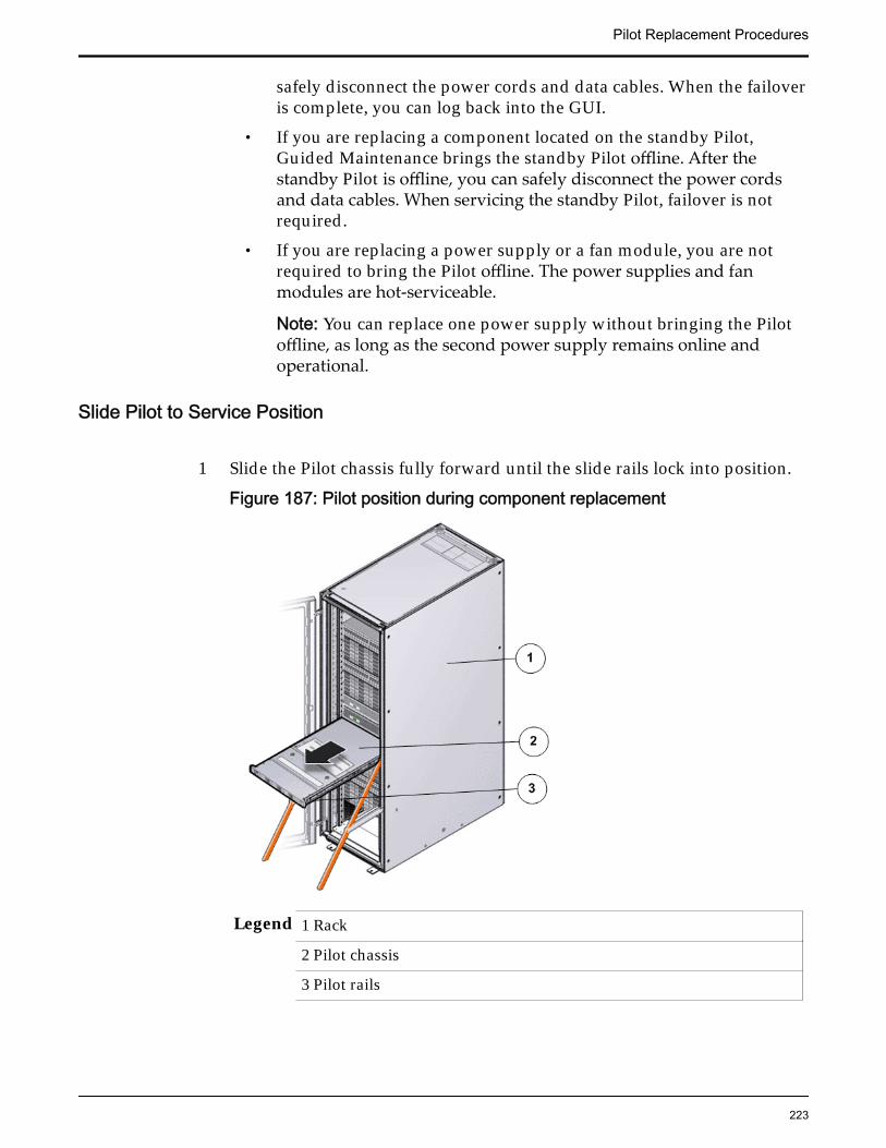
safely disconnect the power cords and data cables. When the failoveris complete, you can log back into the GUI.
• If you are replacing a component located on the standby Pilot,Guided Maintenance brings the standby Pilot offline. After thestandby Pilot is offline, you can safely disconnect the power cordsand data cables. When servicing the standby Pilot, failover is notrequired.
• If you are replacing a power supply or a fan module, you are notrequired to bring the Pilot offline. The power supplies and fanmodules are hot-serviceable.
Note: You can replace one power supply without bringing the Pilotoffline, as long as the second power supply remains online andoperational.
Slide Pilot to Service Position
1 Slide the Pilot chassis fully forward until the slide rails lock into position.
Figure 187: Pilot position during component replacement
Legend 1 Rack
2 Pilot chassis
3 Pilot rails
Pilot Replacement Procedures
223
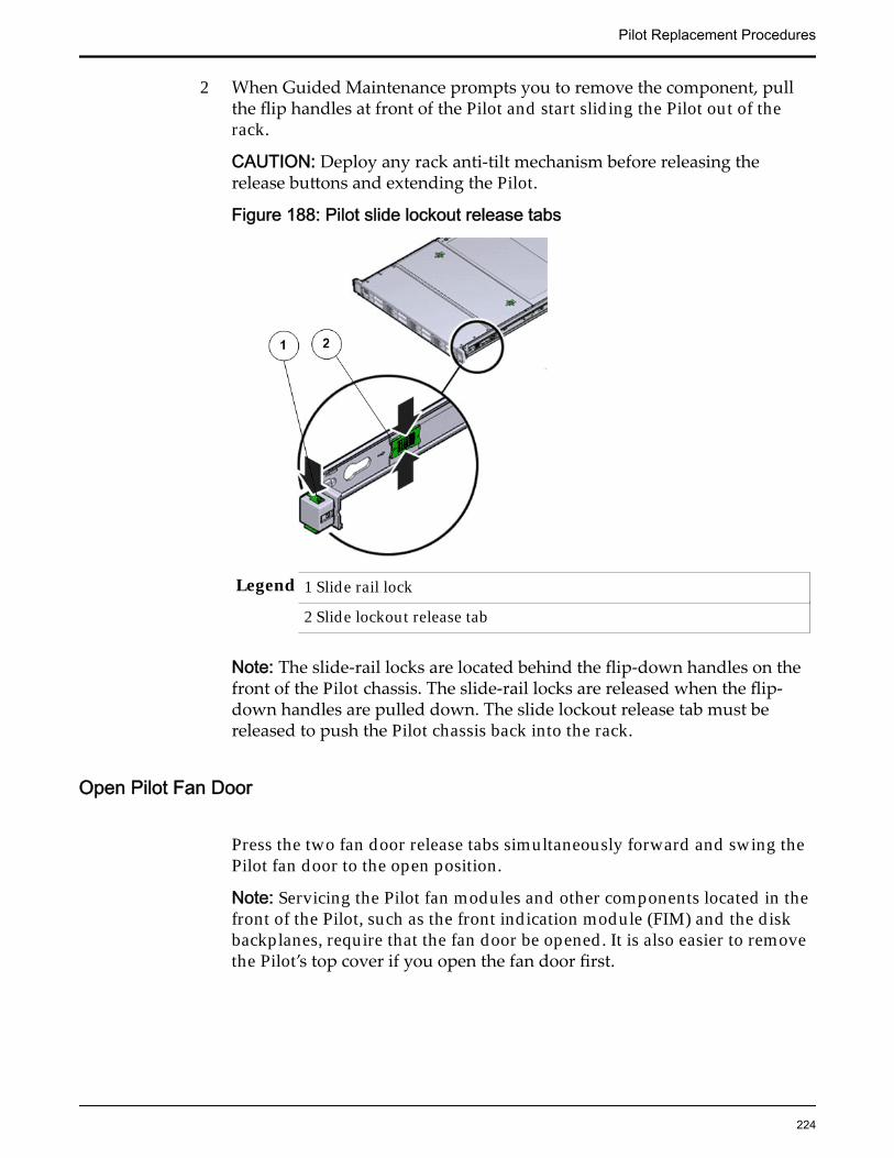
2 When Guided Maintenance prompts you to remove the component, pullthe flip handles at front of the Pilot and start sliding the Pilot out of therack.
CAUTION: Deploy any rack anti-tilt mechanism before releasing therelease buttons and extending the Pilot.
Figure 188: Pilot slide lockout release tabs
Legend 1 Slide rail lock
2 Slide lockout release tab
Note: The slide-rail locks are located behind the flip-down handles on thefront of the Pilot chassis. The slide-rail locks are released when the flip-down handles are pulled down. The slide lockout release tab must bereleased to push the Pilot chassis back into the rack.
Open Pilot Fan Door
Press the two fan door release tabs simultaneously forward and swing thePilot fan door to the open position.
Note: Servicing the Pilot fan modules and other components located in thefront of the Pilot, such as the front indication module (FIM) and the diskbackplanes, require that the fan door be opened. It is also easier to removethe Pilot’s top cover if you open the fan door first.
Pilot Replacement Procedures
224
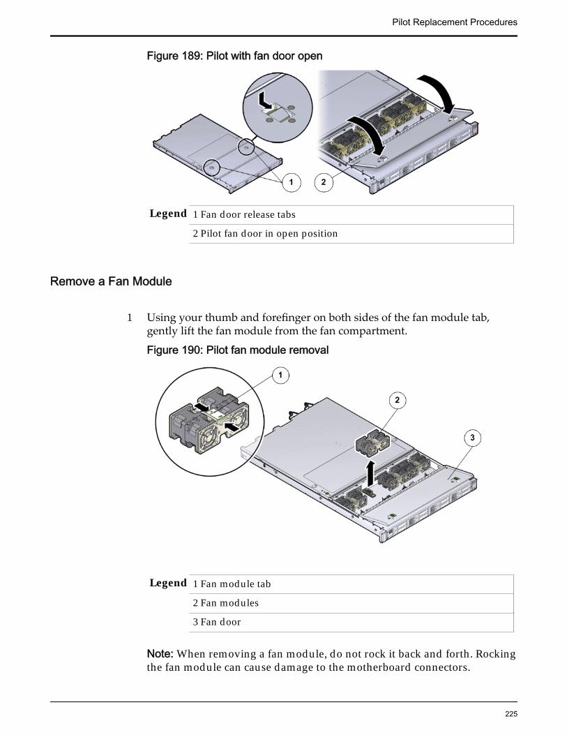
Figure 189: Pilot with fan door open
Legend 1 Fan door release tabs
2 Pilot fan door in open position
Remove a Fan Module
1 Using your thumb and forefinger on both sides of the fan module tab,gently lift the fan module from the fan compartment.
Figure 190: Pilot fan module removal
Legend 1 Fan module tab
2 Fan modules
3 Fan door
Note: When removing a fan module, do not rock it back and forth. Rockingthe fan module can cause damage to the motherboard connectors.
Pilot Replacement Procedures
225
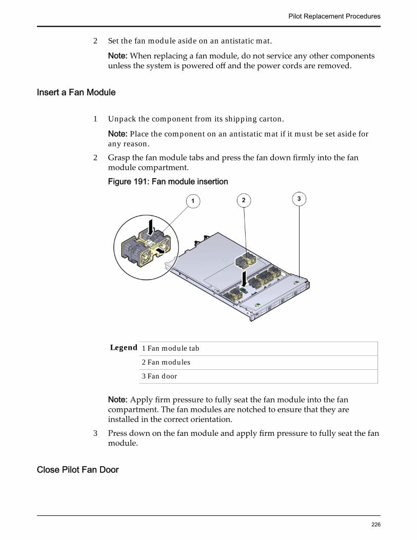
2 Set the fan module aside on an antistatic mat.
Note: When replacing a fan module, do not service any other componentsunless the system is powered off and the power cords are removed.
Insert a Fan Module
1 Unpack the component from its shipping carton.
Note: Place the component on an antistatic mat if it must be set aside forany reason.
2 Grasp the fan module tabs and press the fan down firmly into the fanmodule compartment.
Figure 191: Fan module insertion
Legend 1 Fan module tab
2 Fan modules
3 Fan door
Note: Apply firm pressure to fully seat the fan module into the fancompartment. The fan modules are notched to ensure that they areinstalled in the correct orientation.
3 Press down on the fan module and apply firm pressure to fully seat the fanmodule.
Close Pilot Fan Door
Pilot Replacement Procedures
226
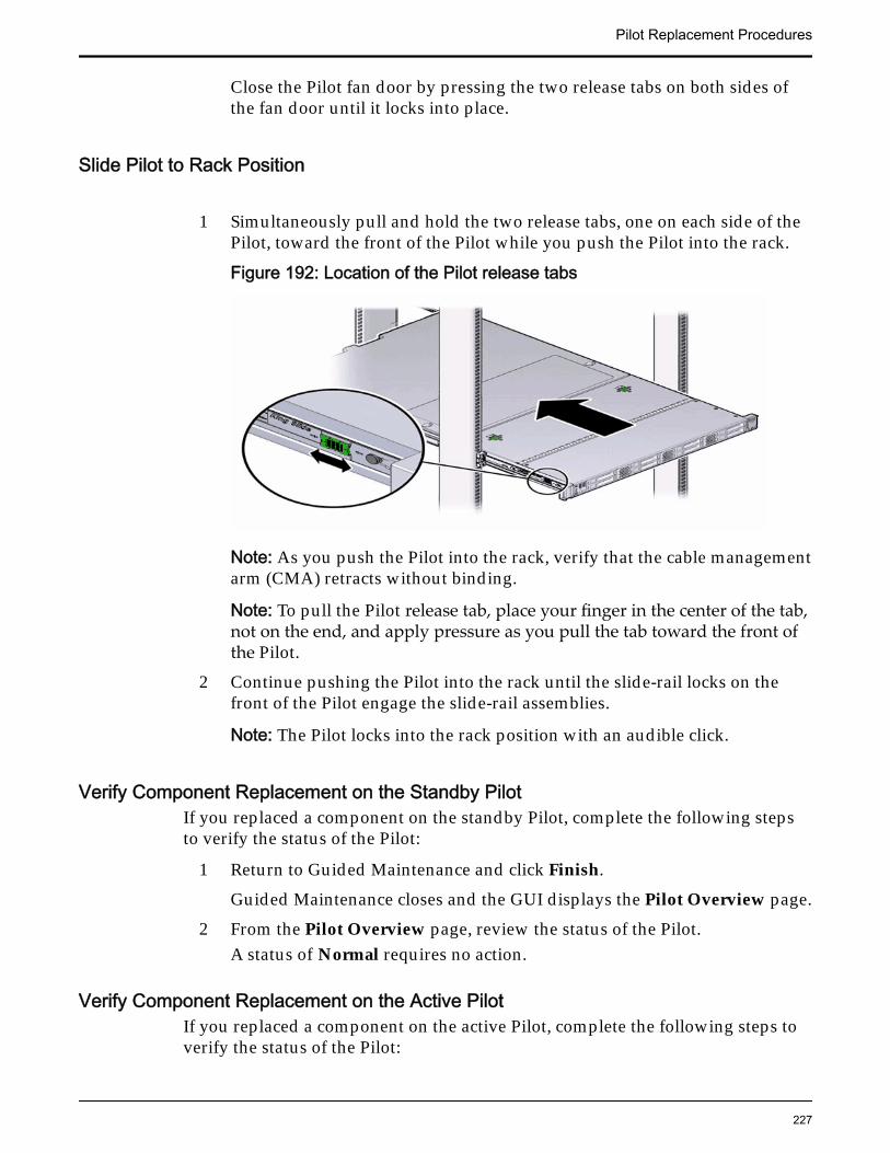
Close the Pilot fan door by pressing the two release tabs on both sides ofthe fan door until it locks into place.
Slide Pilot to Rack Position
1 Simultaneously pull and hold the two release tabs, one on each side of thePilot, toward the front of the Pilot while you push the Pilot into the rack.
Figure 192: Location of the Pilot release tabs
Note: As you push the Pilot into the rack, verify that the cable managementarm (CMA) retracts without binding.
Note: To pull the Pilot release tab, place your finger in the center of the tab,not on the end, and apply pressure as you pull the tab toward the front ofthe Pilot.
2 Continue pushing the Pilot into the rack until the slide-rail locks on thefront of the Pilot engage the slide-rail assemblies.
Note: The Pilot locks into the rack position with an audible click.
Verify Component Replacement on the Standby PilotIf you replaced a component on the standby Pilot, complete the following stepsto verify the status of the Pilot:
1 Return to Guided Maintenance and click Finish.
Guided Maintenance closes and the GUI displays the Pilot Overview page.
2 From the Pilot Overview page, review the status of the Pilot.A status of Normal requires no action.
Verify Component Replacement on the Active PilotIf you replaced a component on the active Pilot, complete the following steps toverify the status of the Pilot:
Pilot Replacement Procedures
227
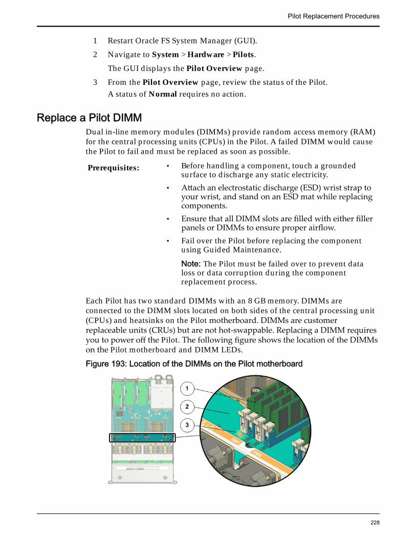
1 Restart Oracle FS System Manager (GUI).
2 Navigate to System > Hardware > Pilots.
The GUI displays the Pilot Overview page.
3 From the Pilot Overview page, review the status of the Pilot.A status of Normal requires no action.
Replace a Pilot DIMMDual in-line memory modules (DIMMs) provide random access memory (RAM)for the central processing units (CPUs) in the Pilot. A failed DIMM would causethe Pilot to fail and must be replaced as soon as possible.
Prerequisites: • Before handling a component, touch a groundedsurface to discharge any static electricity.
• Attach an electrostatic discharge (ESD) wrist strap toyour wrist, and stand on an ESD mat while replacingcomponents.
• Ensure that all DIMM slots are filled with either fillerpanels or DIMMs to ensure proper airflow.
• Fail over the Pilot before replacing the componentusing Guided Maintenance.
Note: The Pilot must be failed over to prevent dataloss or data corruption during the componentreplacement process.
Each Pilot has two standard DIMMs with an 8 GB memory. DIMMs areconnected to the DIMM slots located on both sides of the central processing unit(CPUs) and heatsinks on the Pilot motherboard. DIMMs are customerreplaceable units (CRUs) but are not hot-swappable. Replacing a DIMM requiresyou to power off the Pilot. The following figure shows the location of the DIMMson the Pilot motherboard and DIMM LEDs.
Figure 193: Location of the DIMMs on the Pilot motherboard
Pilot Replacement Procedures
228
Legend 1 DIMMs
2 Motherboard
3 DIMM LED
Note: The DIMMs can be accessed only after removing the cover over the Pilotchassis.
Note: To replace a DIMM, you do not need to remove the Pilot from the rack butextend it along the Pilot rails using the cable management arm (CMA).
Procedure Overview
1 Prepare a Pilot for Component Replacement
2 Power Off the Pilot
3 Slide Pilot to Service Position
4 Open Pilot Fan Door
5 Open Pilot Top Cover
6 Remove a Pilot DIMM
7 Insert a Pilot DIMM
8 Close Pilot Top Cover
9 Close Pilot Fan Door
10 Slide Pilot to Rack Position
11 Connect Power Cords On the Pilot
12 Verify Component Replacement on the Standby Pilot
13 Verify Component Replacement on the Active Pilot
Prepare a Pilot for Component Replacement1 Contact Oracle Customer Support prior to replacing a Pilot component.
Oracle Customer Support identifies the failed component on the Pilot foryou.
2 From Oracle FS System Manager (GUI), navigate to System > Hardware >Pilots and select the Pilot that contains the component that you want toreplace.
3 Select Actions > Repair Pilot.Guided Maintenance displays the list of Pilot components.
4 Based on the information from your Oracle Customer Supportrepresentative, select the correct component from the list.
5 Click Next.Guided Maintenance sends a request to flash the white locate LED on thePilot to help you identify the Pilot in the data center.
Pilot Replacement Procedures
229
6 Click Next.
Guided Maintenance displays a link to Pilot Repair Procedures.
7 Click the Pilot Repair Procedures link to open and print the procedures.
8 Click Next.
• If you are replacing a component located on the active Pilot, GuidedMaintenance brings the active Pilot offline and fails over to thestandby Pilot. After the active Pilot is offline, the GUI closes. You cansafely disconnect the power cords and data cables. When the failoveris complete, you can log back into the GUI.
• If you are replacing a component located on the standby Pilot,Guided Maintenance brings the standby Pilot offline. After thestandby Pilot is offline, you can safely disconnect the power cordsand data cables. When servicing the standby Pilot, failover is notrequired.
• If you are replacing a power supply or a fan module, you are notrequired to bring the Pilot offline. The power supplies and fanmodules are hot-serviceable.
Note: You can replace one power supply without bringing the Pilotoffline, as long as the second power supply remains online andoperational.
Power Off the Pilot
Note: Do not power off the Pilot host without ensuring that SSH is enabled onthe Oracle FS System. Otherwise, the replacement procedure might fail.
1 Notify affected users that the Pilot will be powered off.
2 Ensure that the host of the Pilot on which the replacement procedure mustbe performed is powered off.
Slide Pilot to Service Position
1 Slide the Pilot chassis fully forward until the slide rails lock into position.
Pilot Replacement Procedures
230
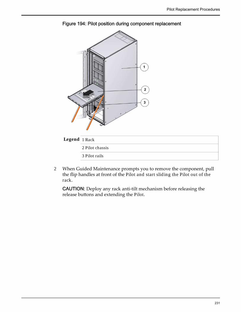
Figure 194: Pilot position during component replacement
Legend 1 Rack
2 Pilot chassis
3 Pilot rails
2 When Guided Maintenance prompts you to remove the component, pullthe flip handles at front of the Pilot and start sliding the Pilot out of therack.
CAUTION: Deploy any rack anti-tilt mechanism before releasing therelease buttons and extending the Pilot.
Pilot Replacement Procedures
231

Figure 195: Pilot slide lockout release tabs
Legend 1 Slide rail lock
2 Slide lockout release tab
Note: The slide-rail locks are located behind the flip-down handles on thefront of the Pilot chassis. The slide-rail locks are released when the flip-down handles are pulled down. The slide lockout release tab must bereleased to push the Pilot chassis back into the rack.
Open Pilot Fan Door
Press the two fan door release tabs simultaneously forward and swing thePilot fan door to the open position.
Note: Servicing the Pilot fan modules and other components located in thefront of the Pilot, such as the front indication module (FIM) and the diskbackplanes, require that the fan door be opened. It is also easier to removethe Pilot’s top cover if you open the fan door first.
Pilot Replacement Procedures
232

Figure 196: Pilot with fan door open
Legend 1 Fan door release tabs
2 Pilot fan door in open position
Open Pilot Top Cover
1 Press down on the push button on the Pilot top cover to release the topcover and use the recessed areas to slide the top cover toward the back ofthe Pilot about 0.5 inches (12.7 mm).
CAUTION: Before removing the top cover of the Pilot, power off the Pilotusing Guided Maintenance. Removing the Pilot top cover before poweringoff the Pilot might cause damage to the software image on the Pilot.
Tip: Slide out the Pilot top cover by pressing down on the grooves locatedon both sides of the cover.
Figure 197: Pilot top cover removal
Legend 1 Push button to release top cover
2 Grooves to slide out top cover
2 Lift the cover off the Pilot chassis and set it aside.
Pilot Replacement Procedures
233
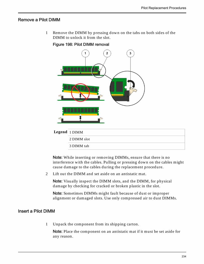
Remove a Pilot DIMM
1 Remove the DIMM by pressing down on the tabs on both sides of theDIMM to unlock it from the slot.
Figure 198: Pilot DIMM removal
Legend 1 DIMM
2 DIMM slot
3 DIMM tab
Note: While inserting or removing DIMMs, ensure that there is nointerference with the cables. Pulling or pressing down on the cables mightcause damage to the cables during the replacement procedure.
2 Lift out the DIMM and set aside on an antistatic mat.
Note: Visually inspect the DIMM slots, and the DIMM, for physicaldamage by checking for cracked or broken plastic in the slot.
Note: Sometimes DIMMs might fault because of dust or improperalignment or damaged slots. Use only compressed air to dust DIMMs.
Insert a Pilot DIMM
1 Unpack the component from its shipping carton.
Note: Place the component on an antistatic mat if it must be set aside forany reason.
Pilot Replacement Procedures
234
2 Press the DIMM fully into the DIMM slot and ensure that the tabs on bothsides of the DIMM are locked.
Important: Ensure that the notch in the DIMM lines up with the key in theslot.
Note: Replace only one DIMM at a time to make sure that they are insertedinto the correct slots. Attempting to insert multiple DIMMs into the slotsmight damage the DIMMs due to excessive flexure.
Note: Never leave a DIMM slot unpopulated. Insert filler panels intoempty DIMM slots to ensure proper air flow inside the Pilot.
Close Pilot Top Cover
1 Place the top cover of the Pilot onto the chassis.
Tip: Place the top cover down so that it hangs over the back of the Pilot byabout 13 mm (0.5 inches) [1] and the side latches align with the slots in thesides of the Pilot chassis.
Note: There are three latching tabs on the sides of the Pilot top cover, twoon the right side and one on the left side when viewing the Pilot from thefront. There is also a latch on the underside of the top cover in the front leftcorner near the release button.
2 Check both sides of the Pilot chassis to ensure that the four corners of thetop cover are fully down and flush with the chassis.
Note: If the cover corners are not flush with the Pilot chassis, slide thecover towards the back of the chassis until you can position the covercorrectly.
Note: If the top cover is not correctly positioned before attempting to slidethe cover forward, the internal latch that is on the underside of the covermight be damaged.
3 Gently slide the top cover along the grooves of the Pilot by pressing downon either side of the top cover until it locks into place and you hear anaudible click.
Pilot Replacement Procedures
235
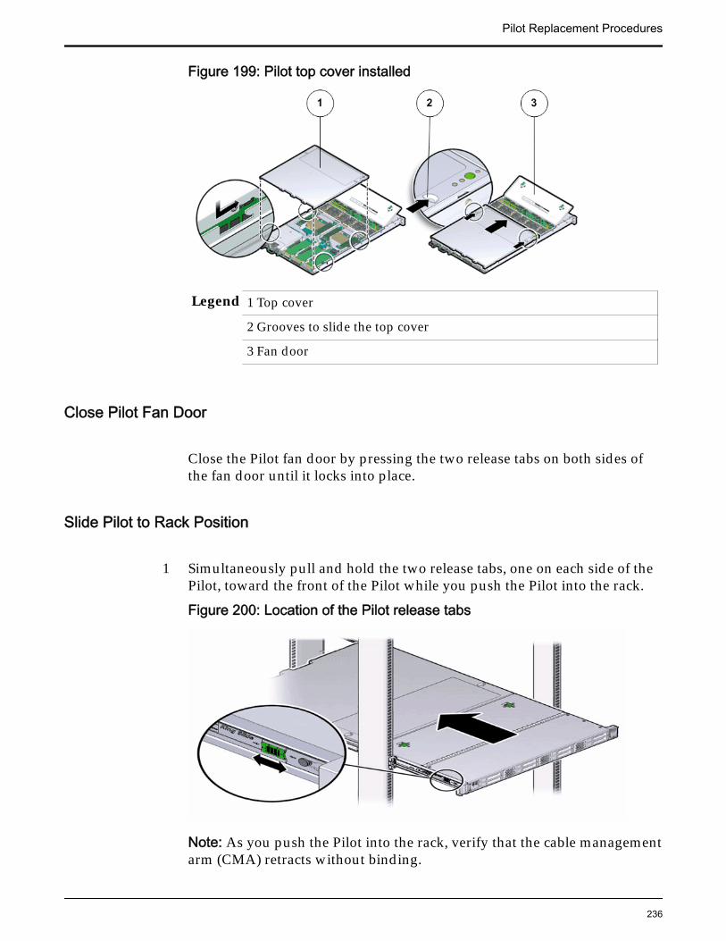
Figure 199: Pilot top cover installed
Legend 1 Top cover
2 Grooves to slide the top cover
3 Fan door
Close Pilot Fan Door
Close the Pilot fan door by pressing the two release tabs on both sides ofthe fan door until it locks into place.
Slide Pilot to Rack Position
1 Simultaneously pull and hold the two release tabs, one on each side of thePilot, toward the front of the Pilot while you push the Pilot into the rack.
Figure 200: Location of the Pilot release tabs
Note: As you push the Pilot into the rack, verify that the cable managementarm (CMA) retracts without binding.
Pilot Replacement Procedures
236
Note: To pull the Pilot release tab, place your finger in the center of the tab,not on the end, and apply pressure as you pull the tab toward the front ofthe Pilot.
2 Continue pushing the Pilot into the rack until the slide-rail locks on thefront of the Pilot engage the slide-rail assemblies.
Note: The Pilot locks into the rack position with an audible click.
Connect Power Cords On the Pilot
Reconnect the power cords to the Pilot.
Note: After the power cords are connected, the green SP LED and the OKLED both start to blink.
Note: Do not turn on the power to the Pilot host immediately. The poweron the Pilot host is turned on only after updating the Pilot BIOS. Turningon the power to the Pilot host early can prevent the Pilot from booting afterthe Pilot BIOS is updated.
Verify Component Replacement on the Standby PilotIf you replaced a component on the standby Pilot, complete the following stepsto verify the status of the Pilot:
1 Return to Guided Maintenance and click Finish.
Guided Maintenance closes and the GUI displays the Pilot Overview page.
2 From the Pilot Overview page, review the status of the Pilot.A status of Normal requires no action.
Verify Component Replacement on the Active PilotIf you replaced a component on the active Pilot, complete the following steps toverify the status of the Pilot:
1 Restart Oracle FS System Manager (GUI).
2 Navigate to System > Hardware > Pilots.
The GUI displays the Pilot Overview page.
3 From the Pilot Overview page, review the status of the Pilot.A status of Normal requires no action.
Pilot Replacement Procedures
237
Replace a Pilot ChassisIf an integrated riveted component of a Pilot chassis is damaged, the chassismust be replaced as soon as possible.
Prerequisites: • Ensure that you have a Phillips Number 2screwdriver with at least a 4-inch shaft.
• Before handling a component, touch a groundedsurface to discharge any static electricity.
• Attach an electrostatic discharge (ESD) wrist strap toyour wrist, and stand on an ESD mat while replacingcomponents.
• Ensure that you have the correct green color codedCPU removal tool that is used for removing smallercore processors. The CPU tool is shipped withreplacement motherboards and replacement CPUs.
• Ensure that there is a workbench available to placethe Pilot chassis once it is removed from the rack forservicing.
• Fail over the Pilot before replacing the componentusing Guided Maintenance.
Note: The Pilot must be failed over to prevent dataloss or data corruption during the componentreplacement process.
Each Oracle Flash Storage System has two Pilots installed in the rack. The Pilotchassis is a customer replaceable unit (CRU). Replacing a Pilot chassis requiresyou to bring the failed Pilot offline and fail over operations to the standby Pilotusing Guided Maintenance.
CAUTION: The Pilot weighs approximately 18.1 kilograms (39.9 pounds). Twopeople are required to carry the Pilot chassis and install it into the rack.
CAUTION: Deploy any rack anti-tilt mechanisms before installing the Pilot intothe rack.
Important: The replacement Pilot ships as a metal chassis without any pre-existing components inside it. Replacement of the Pilot chassis requiresassistance from Oracle Customer Support because it involves removing all FRUsand CRUs from the failed chassis and reinstalling them into the replacementchassis.
CAUTION: Ensure that all power is removed from the failed Pilot beforeremoving the Pilot chassis. You must disconnect the power cords beforeperforming this procedure.
Note: To replace a Pilot chassis, you must remove the failed Pilot from the rack.
Pilot Replacement Procedures
238
Note: Using Guided Maintenance ensures that none of the re-used componentshave failed in case the replacement Pilot is re-using pre-existing components(CRUs and FRUs) from the failed Pilot.
Procedure Overview
1 Prepare a Pilot for Component Replacement
2 Power Off the Pilot
3 Disconnect Pilot Cabling
4 Slide Pilot to Service Position
5 Remove Pilot Chassis From Rack
6 Open Pilot Fan Door
7 Open Pilot Top Cover
8 Remove Components From the Pilot
9 Insert Components on the Pilot
10 Close Pilot Top Cover
11 Close Pilot Fan Door
12 Insert the Pilot Onto the Rack
Prepare a Pilot for Component Replacement1 Contact Oracle Customer Support prior to replacing a Pilot component.
Oracle Customer Support identifies the failed component on the Pilot foryou.
2 From Oracle FS System Manager (GUI), navigate to System > Hardware >Pilots and select the Pilot that contains the component that you want toreplace.
3 Select Actions > Repair Pilot.Guided Maintenance displays the list of Pilot components.
4 Based on the information from your Oracle Customer Supportrepresentative, select the correct component from the list.
5 Click Next.Guided Maintenance sends a request to flash the white locate LED on thePilot to help you identify the Pilot in the data center.
6 Click Next.
Guided Maintenance displays a link to Pilot Repair Procedures.7 Click the Pilot Repair Procedures link to open and print the procedures.8 Click Next.
• If you are replacing a component located on the active Pilot, GuidedMaintenance brings the active Pilot offline and fails over to thestandby Pilot. After the active Pilot is offline, the GUI closes. You can
Pilot Replacement Procedures
239
safely disconnect the power cords and data cables. When the failoveris complete, you can log back into the GUI.
• If you are replacing a component located on the standby Pilot,Guided Maintenance brings the standby Pilot offline. After thestandby Pilot is offline, you can safely disconnect the power cordsand data cables. When servicing the standby Pilot, failover is notrequired.
• If you are replacing a power supply or a fan module, you are notrequired to bring the Pilot offline. The power supplies and fanmodules are hot-serviceable.
Note: You can replace one power supply without bringing the Pilotoffline, as long as the second power supply remains online andoperational.
Power Off the Pilot
Note: Do not power off the Pilot host without ensuring that SSH is enabled onthe Oracle FS System. Otherwise, the replacement procedure might fail.
1 Notify affected users that the Pilot will be powered off.
2 Ensure that the host of the Pilot on which the replacement procedure mustbe performed is powered off.
Disconnect Pilot Cabling
1 Disconnect all power and data cables from the Pilot.These include:
• Ethernet cables connected to the network ports
• Rollover cable connected to the serial port
• Power cables connected to the power supplies of the Pilot
Note: Oracle Customer Support recommends labeling all cables connectedto the Pilot so that they can be re-connected accurately to the Pilot after thereplacement procedure is complete.
Important: Ensure that the Pilot is offline before removing the power cords.
CAUTION: When the Pilot is offline, power is still directed to the powersupply fans in the Pilot. To completely power off the Pilot, you mustdisconnect the power cords from the back of the power supplies.
2 Disconnect the cable management arm (CMA) by pulling the release tabson the left and right side of the CMA.
Note: Do not disconnect the cables attached to the CMA.
Pilot Replacement Procedures
240
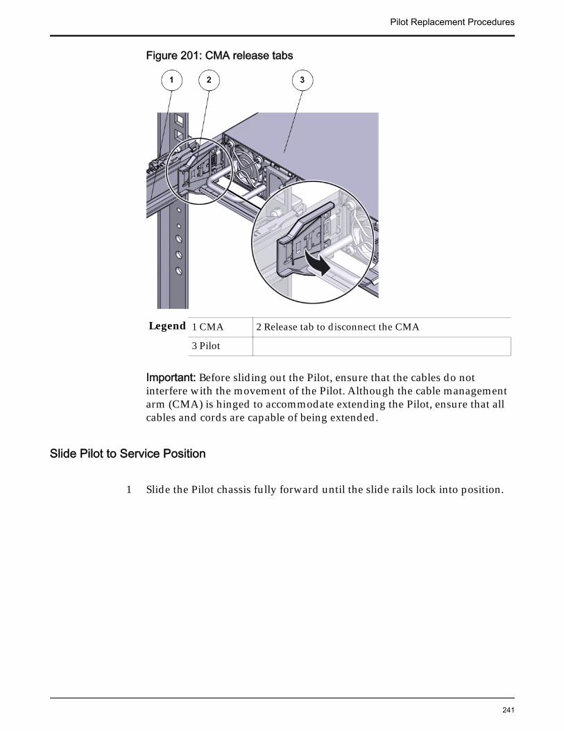
Figure 201: CMA release tabs
Legend 1 CMA 2 Release tab to disconnect the CMA
3 Pilot
Important: Before sliding out the Pilot, ensure that the cables do notinterfere with the movement of the Pilot. Although the cable managementarm (CMA) is hinged to accommodate extending the Pilot, ensure that allcables and cords are capable of being extended.
Slide Pilot to Service Position
1 Slide the Pilot chassis fully forward until the slide rails lock into position.
Pilot Replacement Procedures
241

Figure 202: Pilot position during component replacement
Legend 1 Rack
2 Pilot chassis
3 Pilot rails
2 When Guided Maintenance prompts you to remove the component, pullthe flip handles at front of the Pilot and start sliding the Pilot out of therack.
CAUTION: Deploy any rack anti-tilt mechanism before releasing therelease buttons and extending the Pilot.
Pilot Replacement Procedures
242
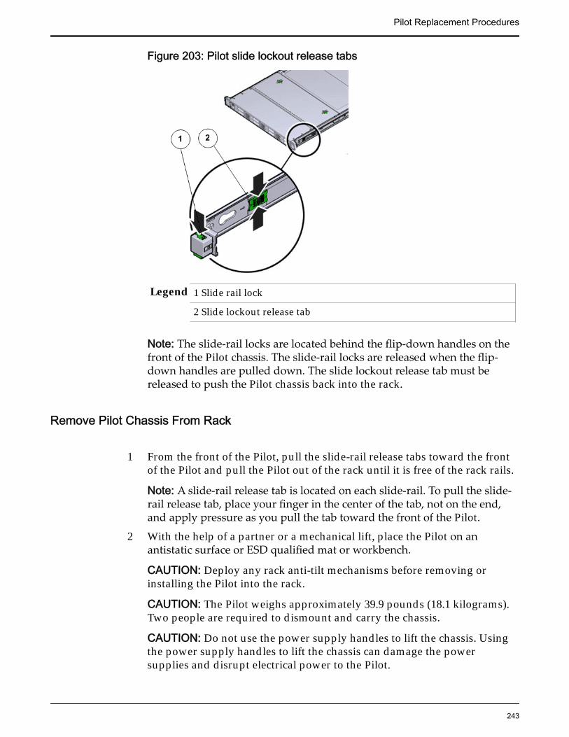
Figure 203: Pilot slide lockout release tabs
Legend 1 Slide rail lock
2 Slide lockout release tab
Note: The slide-rail locks are located behind the flip-down handles on thefront of the Pilot chassis. The slide-rail locks are released when the flip-down handles are pulled down. The slide lockout release tab must bereleased to push the Pilot chassis back into the rack.
Remove Pilot Chassis From Rack
1 From the front of the Pilot, pull the slide-rail release tabs toward the frontof the Pilot and pull the Pilot out of the rack until it is free of the rack rails.
Note: A slide-rail release tab is located on each slide-rail. To pull the slide-rail release tab, place your finger in the center of the tab, not on the end,and apply pressure as you pull the tab toward the front of the Pilot.
2 With the help of a partner or a mechanical lift, place the Pilot on anantistatic surface or ESD qualified mat or workbench.
CAUTION: Deploy any rack anti-tilt mechanisms before removing orinstalling the Pilot into the rack.
CAUTION: The Pilot weighs approximately 39.9 pounds (18.1 kilograms).Two people are required to dismount and carry the chassis.
CAUTION: Do not use the power supply handles to lift the chassis. Usingthe power supply handles to lift the chassis can damage the powersupplies and disrupt electrical power to the Pilot.
Pilot Replacement Procedures
243
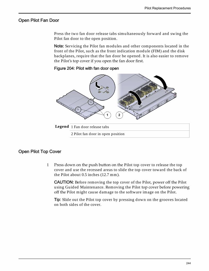
Open Pilot Fan Door
Press the two fan door release tabs simultaneously forward and swing thePilot fan door to the open position.
Note: Servicing the Pilot fan modules and other components located in thefront of the Pilot, such as the front indication module (FIM) and the diskbackplanes, require that the fan door be opened. It is also easier to removethe Pilot’s top cover if you open the fan door first.
Figure 204: Pilot with fan door open
Legend 1 Fan door release tabs
2 Pilot fan door in open position
Open Pilot Top Cover
1 Press down on the push button on the Pilot top cover to release the topcover and use the recessed areas to slide the top cover toward the back ofthe Pilot about 0.5 inches (12.7 mm).
CAUTION: Before removing the top cover of the Pilot, power off the Pilotusing Guided Maintenance. Removing the Pilot top cover before poweringoff the Pilot might cause damage to the software image on the Pilot.
Tip: Slide out the Pilot top cover by pressing down on the grooves locatedon both sides of the cover.
Pilot Replacement Procedures
244
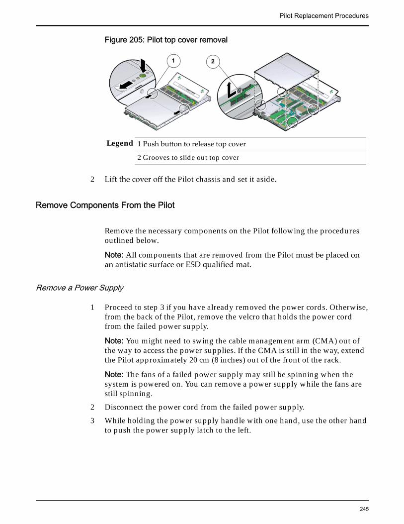
Figure 205: Pilot top cover removal
Legend 1 Push button to release top cover
2 Grooves to slide out top cover
2 Lift the cover off the Pilot chassis and set it aside.
Remove Components From the Pilot
Remove the necessary components on the Pilot following the proceduresoutlined below.
Note: All components that are removed from the Pilot must be placed onan antistatic surface or ESD qualified mat.
Remove a Power Supply
1 Proceed to step 3 if you have already removed the power cords. Otherwise,from the back of the Pilot, remove the velcro that holds the power cordfrom the failed power supply.
Note: You might need to swing the cable management arm (CMA) out ofthe way to access the power supplies. If the CMA is still in the way, extendthe Pilot approximately 20 cm (8 inches) out of the front of the rack.
Note: The fans of a failed power supply may still be spinning when thesystem is powered on. You can remove a power supply while the fans arestill spinning.
2 Disconnect the power cord from the failed power supply.
3 While holding the power supply handle with one hand, use the other handto push the power supply latch to the left.
Pilot Replacement Procedures
245
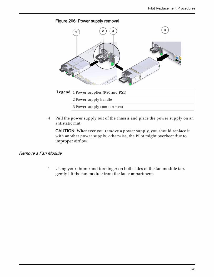
Figure 206: Power supply removal
Legend 1 Power supplies (PS0 and PS1)
2 Power supply handle
3 Power supply compartment
4 Pull the power supply out of the chassis and place the power supply on anantistatic mat.
CAUTION: Whenever you remove a power supply, you should replace itwith another power supply; otherwise, the Pilot might overheat due toimproper airflow.
Remove a Fan Module
1 Using your thumb and forefinger on both sides of the fan module tab,gently lift the fan module from the fan compartment.
Pilot Replacement Procedures
246
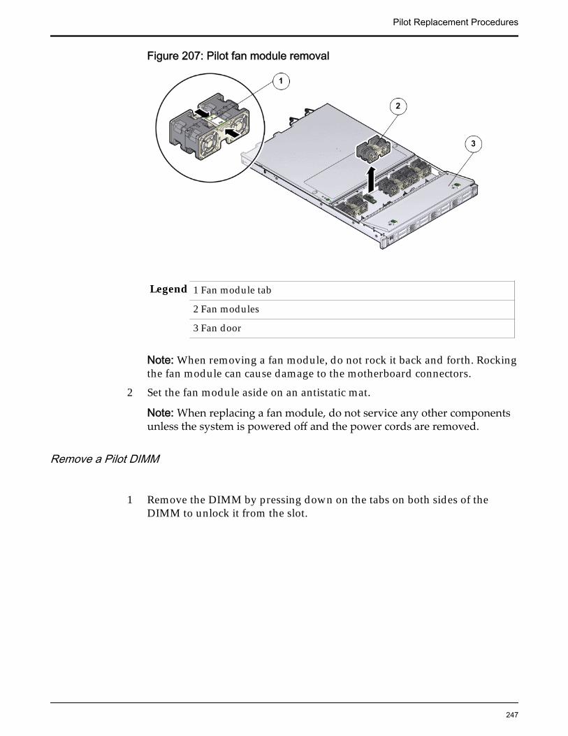
Figure 207: Pilot fan module removal
Legend 1 Fan module tab
2 Fan modules
3 Fan door
Note: When removing a fan module, do not rock it back and forth. Rockingthe fan module can cause damage to the motherboard connectors.
2 Set the fan module aside on an antistatic mat.
Note: When replacing a fan module, do not service any other componentsunless the system is powered off and the power cords are removed.
Remove a Pilot DIMM
1 Remove the DIMM by pressing down on the tabs on both sides of theDIMM to unlock it from the slot.
Pilot Replacement Procedures
247
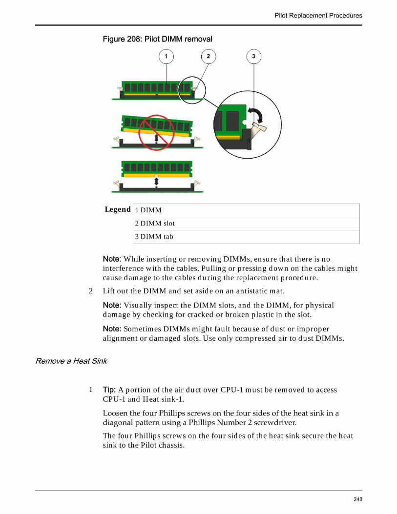
Figure 208: Pilot DIMM removal
Legend 1 DIMM
2 DIMM slot
3 DIMM tab
Note: While inserting or removing DIMMs, ensure that there is nointerference with the cables. Pulling or pressing down on the cables mightcause damage to the cables during the replacement procedure.
2 Lift out the DIMM and set aside on an antistatic mat.
Note: Visually inspect the DIMM slots, and the DIMM, for physicaldamage by checking for cracked or broken plastic in the slot.
Note: Sometimes DIMMs might fault because of dust or improperalignment or damaged slots. Use only compressed air to dust DIMMs.
Remove a Heat Sink
1 Tip: A portion of the air duct over CPU-1 must be removed to accessCPU-1 and Heat sink-1.
Loosen the four Phillips screws on the four sides of the heat sink in adiagonal pattern using a Phillips Number 2 screwdriver.
The four Phillips screws on the four sides of the heat sink secure the heatsink to the Pilot chassis.
Pilot Replacement Procedures
248
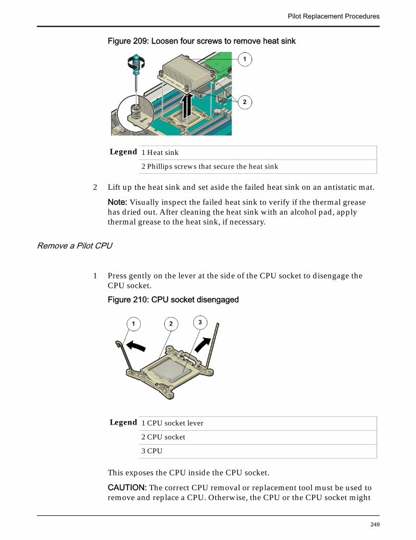
Figure 209: Loosen four screws to remove heat sink
Legend 1 Heat sink
2 Phillips screws that secure the heat sink
2 Lift up the heat sink and set aside the failed heat sink on an antistatic mat.
Note: Visually inspect the failed heat sink to verify if the thermal greasehas dried out. After cleaning the heat sink with an alcohol pad, applythermal grease to the heat sink, if necessary.
Remove a Pilot CPU
1 Press gently on the lever at the side of the CPU socket to disengage theCPU socket.
Figure 210: CPU socket disengaged
Legend 1 CPU socket lever
2 CPU socket
3 CPU
This exposes the CPU inside the CPU socket.
CAUTION: The correct CPU removal or replacement tool must be used toremove and replace a CPU. Otherwise, the CPU or the CPU socket might
Pilot Replacement Procedures
249
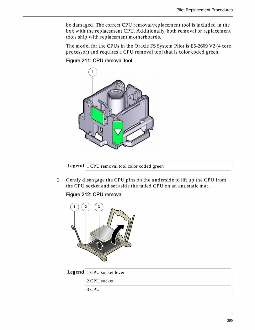
be damaged. The correct CPU removal/replacement tool is included in thebox with the replacement CPU. Additionally, both removal or replacementtools ship with replacement motherboards.
The model for the CPUs in the Oracle FS System Pilot is E5-2609 V2 (4 coreprocessor) and requires a CPU removal tool that is color coded green.
Figure 211: CPU removal tool
Legend 1 CPU removal tool color coded green
2 Gently disengage the CPU pins on the underside to lift up the CPU fromthe CPU socket and set aside the failed CPU on an antistatic mat.
Figure 212: CPU removal
Legend 1 CPU socket lever
2 CPU socket
3 CPU
Pilot Replacement Procedures
250
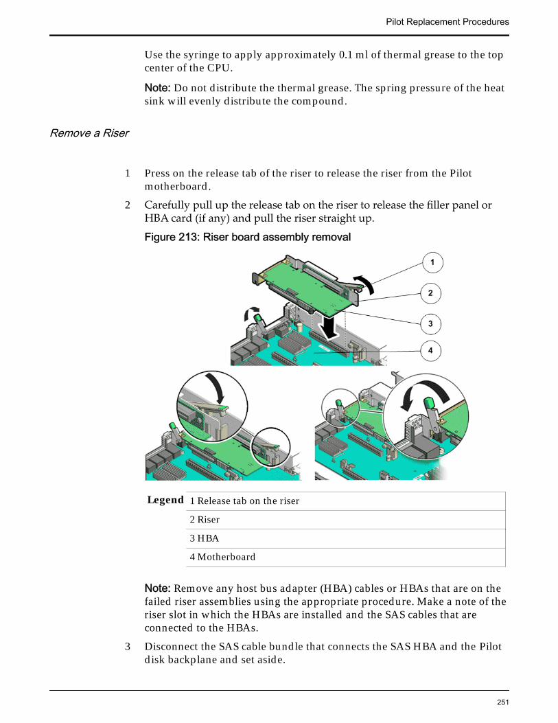
Use the syringe to apply approximately 0.1 ml of thermal grease to the topcenter of the CPU.
Note: Do not distribute the thermal grease. The spring pressure of the heatsink will evenly distribute the compound.
Remove a Riser
1 Press on the release tab of the riser to release the riser from the Pilotmotherboard.
2 Carefully pull up the release tab on the riser to release the filler panel orHBA card (if any) and pull the riser straight up.
Figure 213: Riser board assembly removal
Legend 1 Release tab on the riser
2 Riser
3 HBA
4 Motherboard
Note: Remove any host bus adapter (HBA) cables or HBAs that are on thefailed riser assemblies using the appropriate procedure. Make a note of theriser slot in which the HBAs are installed and the SAS cables that areconnected to the HBAs.
3 Disconnect the SAS cable bundle that connects the SAS HBA and the Pilotdisk backplane and set aside.
Pilot Replacement Procedures
251
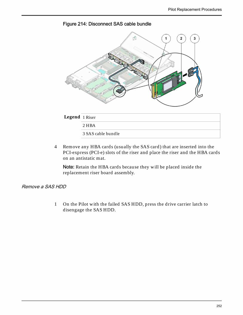
Figure 214: Disconnect SAS cable bundle
Legend 1 Riser
2 HBA
3 SAS cable bundle
4 Remove any HBA cards (usually the SAS card) that are inserted into thePCI-express (PCI-e) slots of the riser and place the riser and the HBA cardson an antistatic mat.
Note: Retain the HBA cards because they will be placed inside thereplacement riser board assembly.
Remove a SAS HDD
1 On the Pilot with the failed SAS HDD, press the drive carrier latch todisengage the SAS HDD.
Pilot Replacement Procedures
252
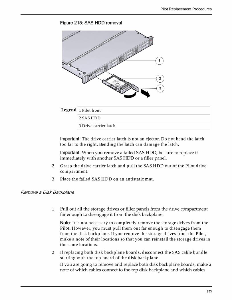
Figure 215: SAS HDD removal
Legend 1 Pilot front
2 SAS HDD
3 Drive carrier latch
Important: The drive carrier latch is not an ejector. Do not bend the latchtoo far to the right. Bending the latch can damage the latch.
Important: When you remove a failed SAS HDD, be sure to replace itimmediately with another SAS HDD or a filler panel.
2 Grasp the drive carrier latch and pull the SAS HDD out of the Pilot drivecompartment.
3 Place the failed SAS HDD on an antistatic mat.
Remove a Disk Backplane
1 Pull out all the storage drives or filler panels from the drive compartmentfar enough to disengage it from the disk backplane.
Note: It is not necessary to completely remove the storage drives from thePilot. However, you must pull them out far enough to disengage themfrom the disk backplane. If you remove the storage drives from the Pilot,make a note of their locations so that you can reinstall the storage drives inthe same locations.
2 If replacing both disk backplane boards, disconnect the SAS cable bundlestarting with the top board of the disk backplane.If you are going to remove and replace both disk backplane boards, make anote of which cables connect to the top disk backplane and which cables
Pilot Replacement Procedures
253
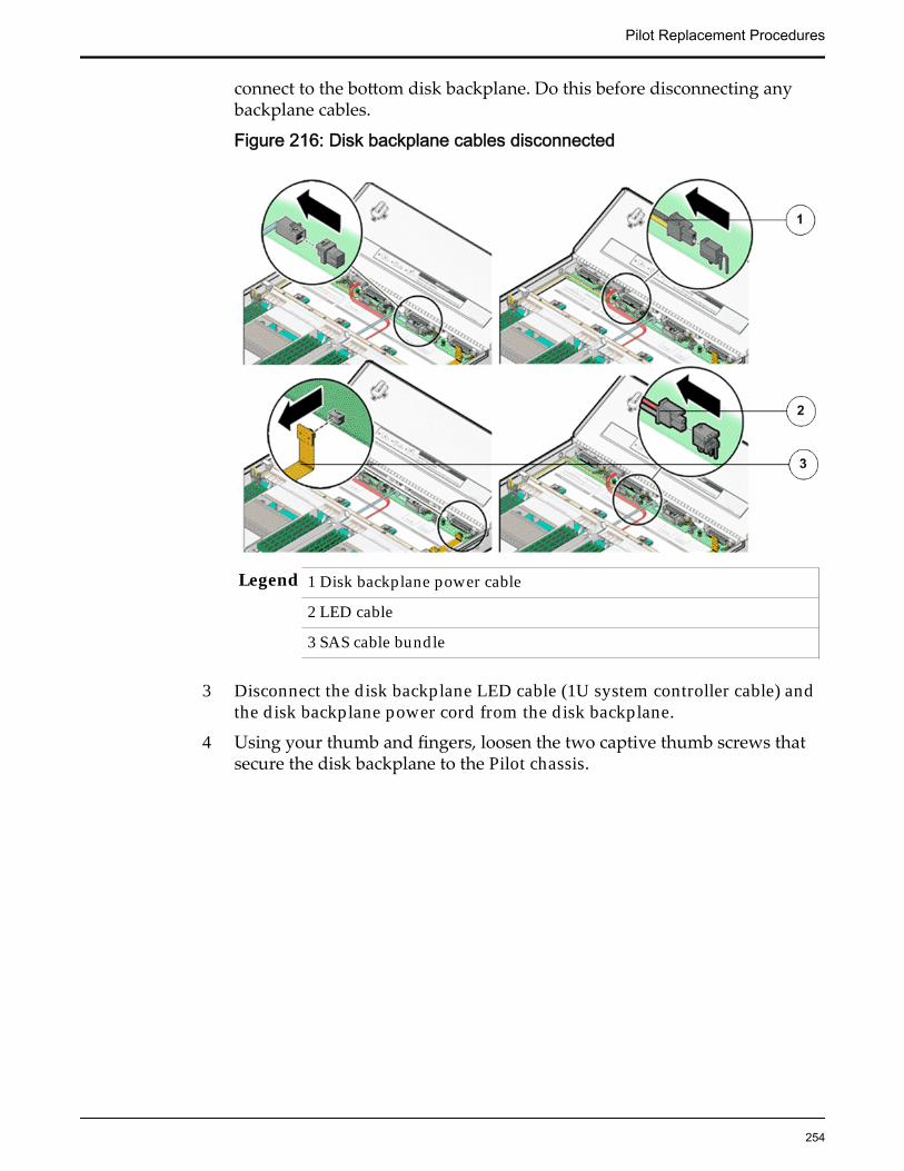
connect to the bottom disk backplane. Do this before disconnecting anybackplane cables.
Figure 216: Disk backplane cables disconnected
Legend 1 Disk backplane power cable
2 LED cable
3 SAS cable bundle
3 Disconnect the disk backplane LED cable (1U system controller cable) andthe disk backplane power cord from the disk backplane.
4 Using your thumb and fingers, loosen the two captive thumb screws thatsecure the disk backplane to the Pilot chassis.
Pilot Replacement Procedures
254
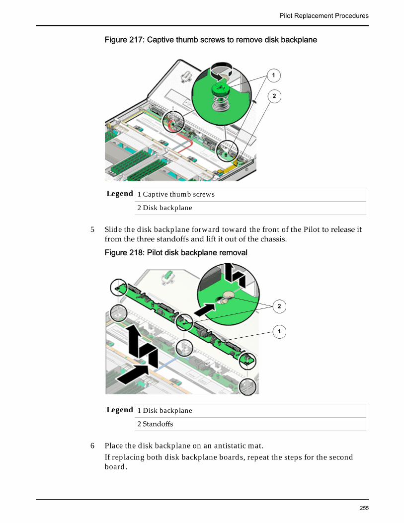
Figure 217: Captive thumb screws to remove disk backplane
Legend 1 Captive thumb screws
2 Disk backplane
5 Slide the disk backplane forward toward the front of the Pilot to release itfrom the three standoffs and lift it out of the chassis.
Figure 218: Pilot disk backplane removal
Legend 1 Disk backplane
2 Standoffs
6 Place the disk backplane on an antistatic mat.If replacing both disk backplane boards, repeat the steps for the secondboard.
Pilot Replacement Procedures
255
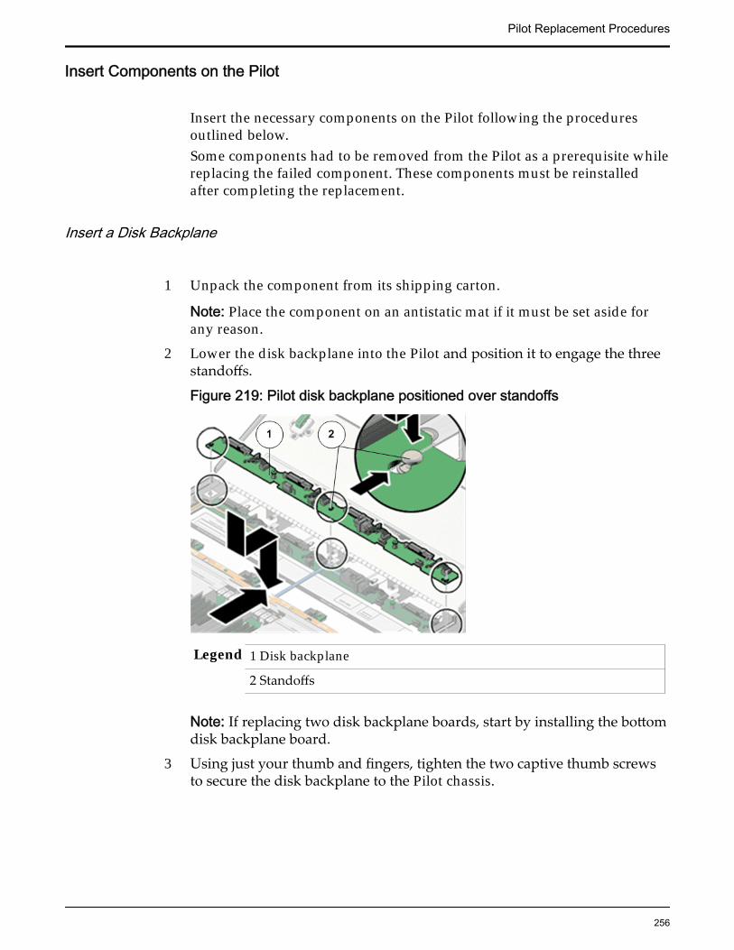
Insert Components on the Pilot
Insert the necessary components on the Pilot following the proceduresoutlined below.Some components had to be removed from the Pilot as a prerequisite whilereplacing the failed component. These components must be reinstalledafter completing the replacement.
Insert a Disk Backplane
1 Unpack the component from its shipping carton.
Note: Place the component on an antistatic mat if it must be set aside forany reason.
2 Lower the disk backplane into the Pilot and position it to engage the threestandoffs.
Figure 219: Pilot disk backplane positioned over standoffs
Legend 1 Disk backplane
2 Standoffs
Note: If replacing two disk backplane boards, start by installing the bottomdisk backplane board.
3 Using just your thumb and fingers, tighten the two captive thumb screwsto secure the disk backplane to the Pilot chassis.
Pilot Replacement Procedures
256
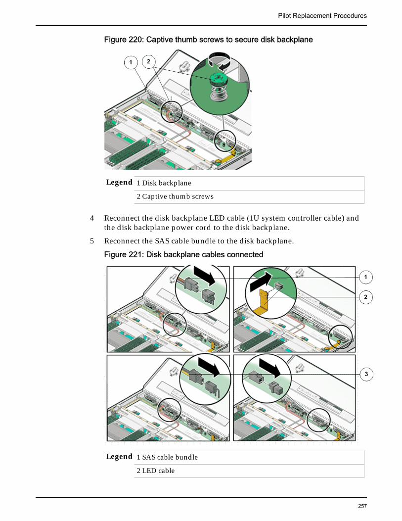
Figure 220: Captive thumb screws to secure disk backplane
Legend 1 Disk backplane
2 Captive thumb screws
4 Reconnect the disk backplane LED cable (1U system controller cable) andthe disk backplane power cord to the disk backplane.
5 Reconnect the SAS cable bundle to the disk backplane.
Figure 221: Disk backplane cables connected
Legend 1 SAS cable bundle
2 LED cable
Pilot Replacement Procedures
257
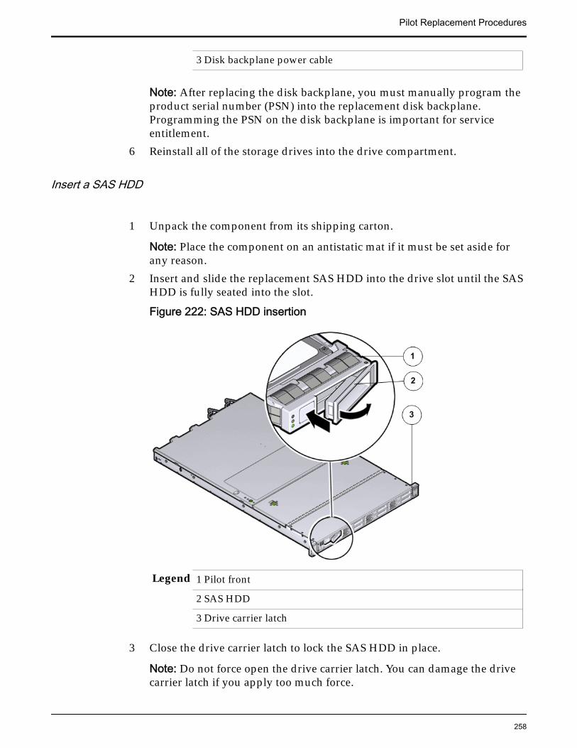
3 Disk backplane power cable
Note: After replacing the disk backplane, you must manually program theproduct serial number (PSN) into the replacement disk backplane.Programming the PSN on the disk backplane is important for serviceentitlement.
6 Reinstall all of the storage drives into the drive compartment.
Insert a SAS HDD
1 Unpack the component from its shipping carton.
Note: Place the component on an antistatic mat if it must be set aside forany reason.
2 Insert and slide the replacement SAS HDD into the drive slot until the SASHDD is fully seated into the slot.
Figure 222: SAS HDD insertion
Legend 1 Pilot front
2 SAS HDD
3 Drive carrier latch
3 Close the drive carrier latch to lock the SAS HDD in place.
Note: Do not force open the drive carrier latch. You can damage the drivecarrier latch if you apply too much force.
Pilot Replacement Procedures
258
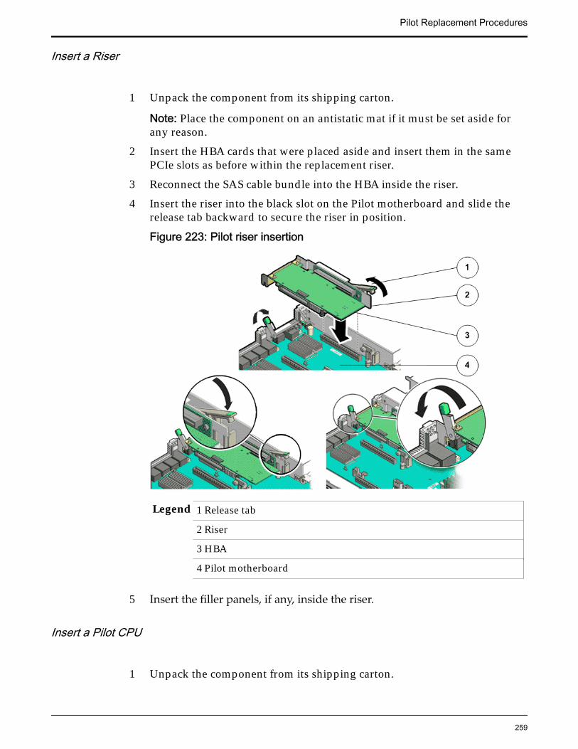
Insert a Riser
1 Unpack the component from its shipping carton.
Note: Place the component on an antistatic mat if it must be set aside forany reason.
2 Insert the HBA cards that were placed aside and insert them in the samePCIe slots as before within the replacement riser.
3 Reconnect the SAS cable bundle into the HBA inside the riser.
4 Insert the riser into the black slot on the Pilot motherboard and slide therelease tab backward to secure the riser in position.
Figure 223: Pilot riser insertion
Legend 1 Release tab
2 Riser
3 HBA
4 Pilot motherboard
5 Insert the filler panels, if any, inside the riser.
Insert a Pilot CPU
1 Unpack the component from its shipping carton.
Pilot Replacement Procedures
259
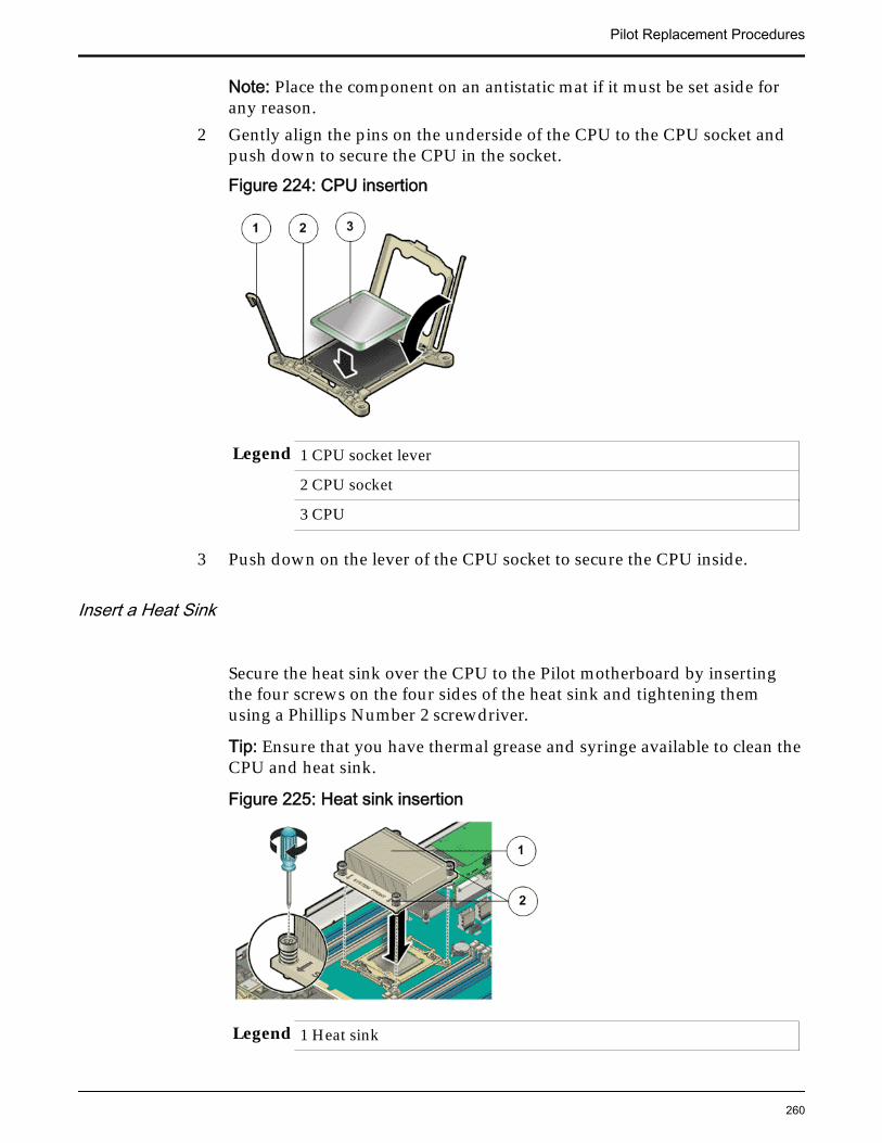
Note: Place the component on an antistatic mat if it must be set aside forany reason.
2 Gently align the pins on the underside of the CPU to the CPU socket andpush down to secure the CPU in the socket.
Figure 224: CPU insertion
Legend 1 CPU socket lever
2 CPU socket
3 CPU
3 Push down on the lever of the CPU socket to secure the CPU inside.
Insert a Heat Sink
Secure the heat sink over the CPU to the Pilot motherboard by insertingthe four screws on the four sides of the heat sink and tightening themusing a Phillips Number 2 screwdriver.
Tip: Ensure that you have thermal grease and syringe available to clean theCPU and heat sink.
Figure 225: Heat sink insertion
Legend 1 Heat sink
Pilot Replacement Procedures
260
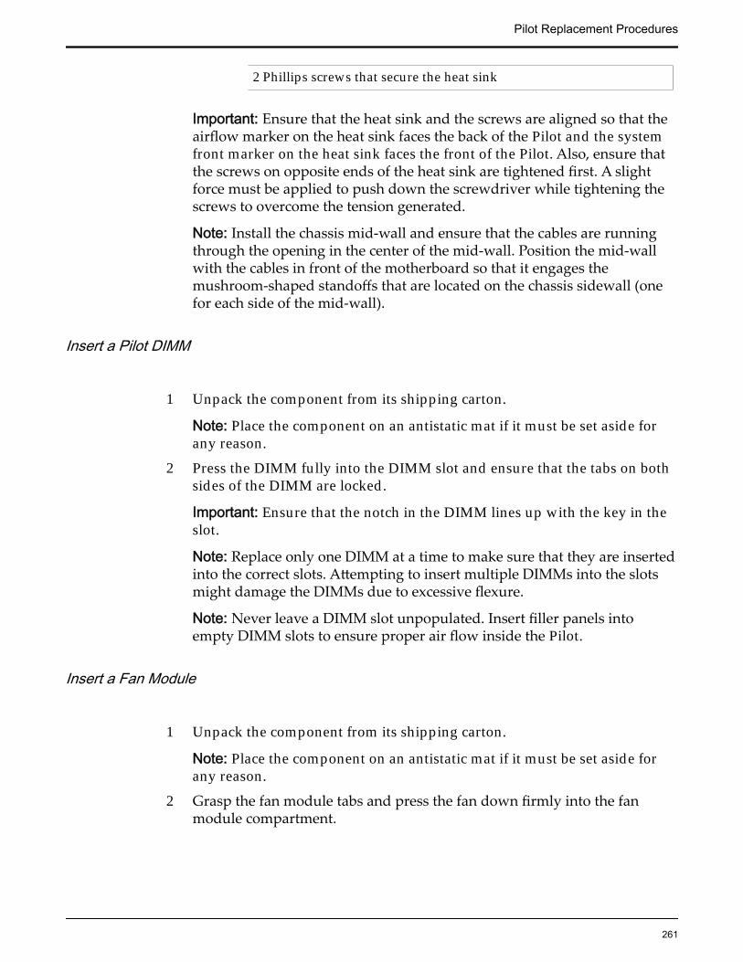
2 Phillips screws that secure the heat sink
Important: Ensure that the heat sink and the screws are aligned so that theairflow marker on the heat sink faces the back of the Pilot and the systemfront marker on the heat sink faces the front of the Pilot. Also, ensure thatthe screws on opposite ends of the heat sink are tightened first. A slightforce must be applied to push down the screwdriver while tightening thescrews to overcome the tension generated.
Note: Install the chassis mid-wall and ensure that the cables are runningthrough the opening in the center of the mid-wall. Position the mid-wallwith the cables in front of the motherboard so that it engages themushroom-shaped standoffs that are located on the chassis sidewall (onefor each side of the mid-wall).
Insert a Pilot DIMM
1 Unpack the component from its shipping carton.
Note: Place the component on an antistatic mat if it must be set aside forany reason.
2 Press the DIMM fully into the DIMM slot and ensure that the tabs on bothsides of the DIMM are locked.
Important: Ensure that the notch in the DIMM lines up with the key in theslot.
Note: Replace only one DIMM at a time to make sure that they are insertedinto the correct slots. Attempting to insert multiple DIMMs into the slotsmight damage the DIMMs due to excessive flexure.
Note: Never leave a DIMM slot unpopulated. Insert filler panels intoempty DIMM slots to ensure proper air flow inside the Pilot.
Insert a Fan Module
1 Unpack the component from its shipping carton.
Note: Place the component on an antistatic mat if it must be set aside forany reason.
2 Grasp the fan module tabs and press the fan down firmly into the fanmodule compartment.
Pilot Replacement Procedures
261
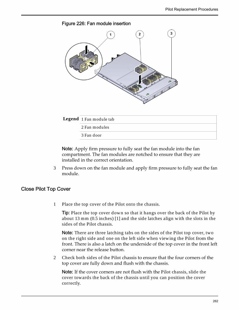
Figure 226: Fan module insertion
Legend 1 Fan module tab
2 Fan modules
3 Fan door
Note: Apply firm pressure to fully seat the fan module into the fancompartment. The fan modules are notched to ensure that they areinstalled in the correct orientation.
3 Press down on the fan module and apply firm pressure to fully seat the fanmodule.
Close Pilot Top Cover
1 Place the top cover of the Pilot onto the chassis.
Tip: Place the top cover down so that it hangs over the back of the Pilot byabout 13 mm (0.5 inches) [1] and the side latches align with the slots in thesides of the Pilot chassis.
Note: There are three latching tabs on the sides of the Pilot top cover, twoon the right side and one on the left side when viewing the Pilot from thefront. There is also a latch on the underside of the top cover in the front leftcorner near the release button.
2 Check both sides of the Pilot chassis to ensure that the four corners of thetop cover are fully down and flush with the chassis.
Note: If the cover corners are not flush with the Pilot chassis, slide thecover towards the back of the chassis until you can position the covercorrectly.
Pilot Replacement Procedures
262
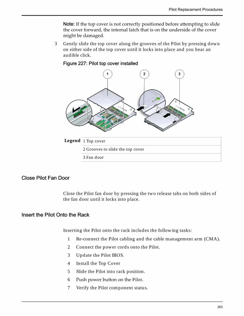
Note: If the top cover is not correctly positioned before attempting to slidethe cover forward, the internal latch that is on the underside of the covermight be damaged.
3 Gently slide the top cover along the grooves of the Pilot by pressing downon either side of the top cover until it locks into place and you hear anaudible click.
Figure 227: Pilot top cover installed
Legend 1 Top cover
2 Grooves to slide the top cover
3 Fan door
Close Pilot Fan Door
Close the Pilot fan door by pressing the two release tabs on both sides ofthe fan door until it locks into place.
Insert the Pilot Onto the Rack
Inserting the Pilot onto the rack includes the following tasks:
1 Re-connect the Pilot cabling and the cable management arm (CMA).
2 Connect the power cords onto the Pilot.
3 Update the Pilot BIOS.
4 Install the Top Cover
5 Slide the Pilot into rack position.
6 Push power button on the Pilot.
7 Verify the Pilot component status.
Pilot Replacement Procedures
263
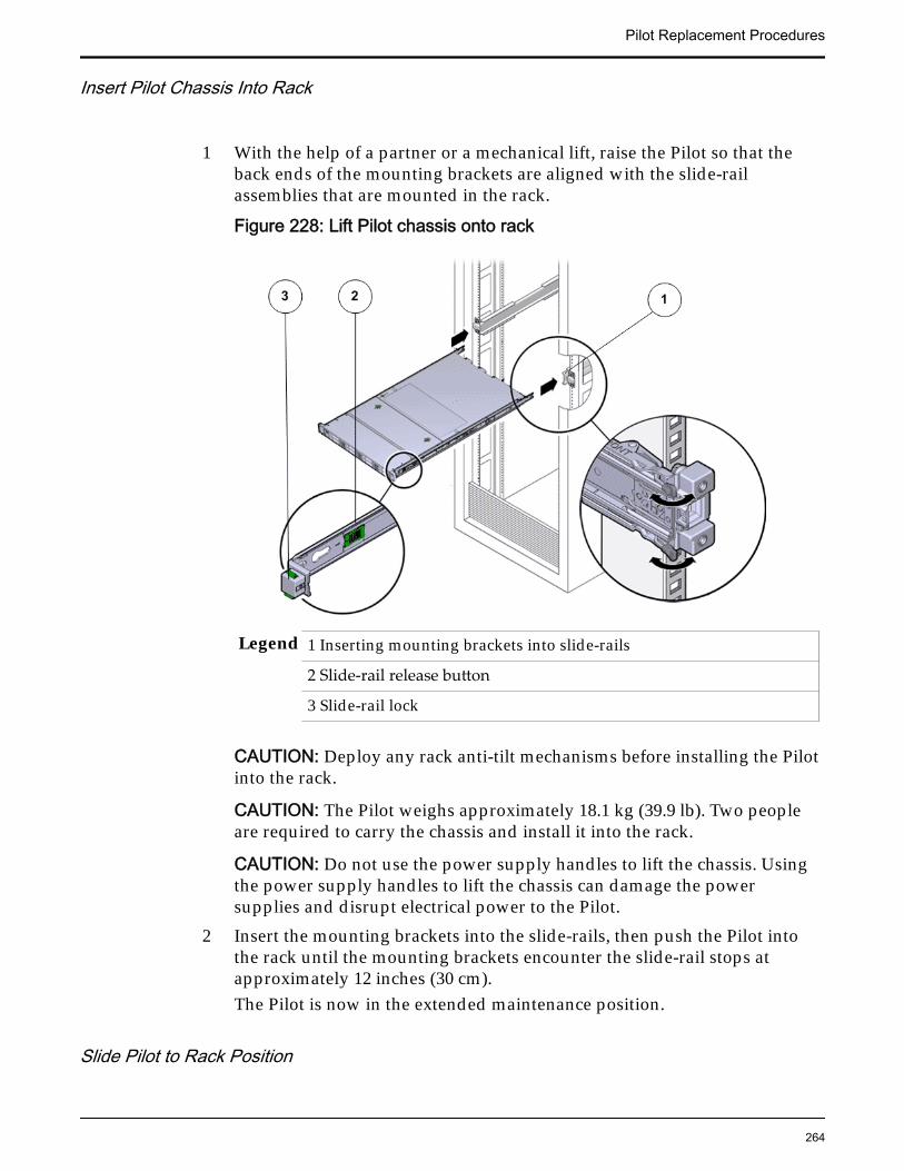
Insert Pilot Chassis Into Rack
1 With the help of a partner or a mechanical lift, raise the Pilot so that theback ends of the mounting brackets are aligned with the slide-railassemblies that are mounted in the rack.
Figure 228: Lift Pilot chassis onto rack
Legend 1 Inserting mounting brackets into slide-rails
2 Slide-rail release button
3 Slide-rail lock
CAUTION: Deploy any rack anti-tilt mechanisms before installing the Pilotinto the rack.
CAUTION: The Pilot weighs approximately 18.1 kg (39.9 lb). Two peopleare required to carry the chassis and install it into the rack.
CAUTION: Do not use the power supply handles to lift the chassis. Usingthe power supply handles to lift the chassis can damage the powersupplies and disrupt electrical power to the Pilot.
2 Insert the mounting brackets into the slide-rails, then push the Pilot intothe rack until the mounting brackets encounter the slide-rail stops atapproximately 12 inches (30 cm).The Pilot is now in the extended maintenance position.
Slide Pilot to Rack Position
Pilot Replacement Procedures
264
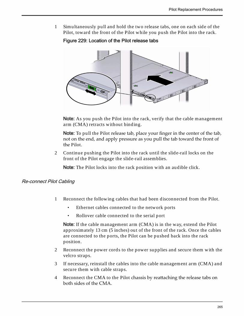
1 Simultaneously pull and hold the two release tabs, one on each side of thePilot, toward the front of the Pilot while you push the Pilot into the rack.
Figure 229: Location of the Pilot release tabs
Note: As you push the Pilot into the rack, verify that the cable managementarm (CMA) retracts without binding.
Note: To pull the Pilot release tab, place your finger in the center of the tab,not on the end, and apply pressure as you pull the tab toward the front ofthe Pilot.
2 Continue pushing the Pilot into the rack until the slide-rail locks on thefront of the Pilot engage the slide-rail assemblies.
Note: The Pilot locks into the rack position with an audible click.
Re-connect Pilot Cabling
1 Reconnect the following cables that had been disconnected from the Pilot.
• Ethernet cables connected to the network ports
• Rollover cable connected to the serial port
Note: If the cable management arm (CMA) is in the way, extend the Pilotapproximately 13 cm (5 inches) out of the front of the rack. Once the cablesare connected to the ports, the Pilot can be pushed back into the rackposition.
2 Reconnect the power cords to the power supplies and secure them with thevelcro straps.
3 If necessary, reinstall the cables into the cable management arm (CMA) andsecure them with cable straps.
4 Reconnect the CMA to the Pilot chassis by reattaching the release tabs onboth sides of the CMA.
Pilot Replacement Procedures
265
Connect Power Cords On the Pilot
Reconnect the power cords to the Pilot.
Note: After the power cords are connected, the green SP LED and the OKLED both start to blink.
Note: Do not turn on the power to the Pilot host immediately. The poweron the Pilot host is turned on only after updating the Pilot BIOS. Turningon the power to the Pilot host early can prevent the Pilot from booting afterthe Pilot BIOS is updated.
Verify Component Replacement on the Standby PilotIf you replaced a component on the standby Pilot, complete the following stepsto verify the status of the Pilot:
1 Return to Guided Maintenance and click Finish.
Guided Maintenance closes and the GUI displays the Pilot Overview page.
2 From the Pilot Overview page, review the status of the Pilot.A status of Normal requires no action.
Verify Component Replacement on the Active PilotIf you replaced a component on the active Pilot, complete the following steps toverify the status of the Pilot:
1 Restart Oracle FS System Manager (GUI).
2 Navigate to System > Hardware > Pilots.
The GUI displays the Pilot Overview page.
3 From the Pilot Overview page, review the status of the Pilot.A status of Normal requires no action.
Pilot Replacement Procedures
266
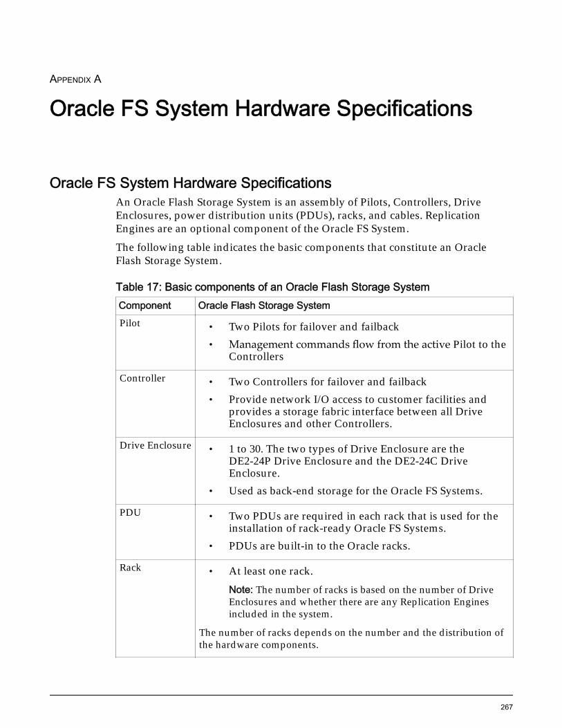
APPENDIX A
Oracle FS System Hardware Specifications
Oracle FS System Hardware SpecificationsAn Oracle Flash Storage System is an assembly of Pilots, Controllers, DriveEnclosures, power distribution units (PDUs), racks, and cables. ReplicationEngines are an optional component of the Oracle FS System.
The following table indicates the basic components that constitute an OracleFlash Storage System.
Table 17: Basic components of an Oracle Flash Storage SystemComponent Oracle Flash Storage SystemPilot • Two Pilots for failover and failback
• Management commands flow from the active Pilot to theControllers
Controller • Two Controllers for failover and failback• Provide network I/O access to customer facilities and
provides a storage fabric interface between all DriveEnclosures and other Controllers.
Drive Enclosure • 1 to 30. The two types of Drive Enclosure are theDE2-24P Drive Enclosure and the DE2-24C DriveEnclosure.
• Used as back-end storage for the Oracle FS Systems.
PDU • Two PDUs are required in each rack that is used for theinstallation of rack-ready Oracle FS Systems.
• PDUs are built-in to the Oracle racks.
Rack • At least one rack.Note: The number of racks is based on the number of DriveEnclosures and whether there are any Replication Enginesincluded in the system.
The number of racks depends on the number and the distribution ofthe hardware components.
267
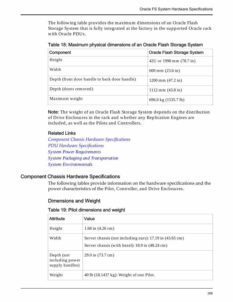
The following table provides the maximum dimensions of an Oracle FlashStorage System that is fully integrated at the factory in the supported Oracle rackwith Oracle PDUs.
Table 18: Maximum physical dimensions of an Oracle Flash Storage SystemComponent Oracle Flash Storage SystemHeight 42U or 1998 mm (78.7 in)
Width 600 mm (23.6 in)
Depth (front door handle to back door handle) 1200 mm (47.2 in)
Depth (doors removed) 1112 mm (43.8 in)
Maximum weight 696.6 kg (1535.7 lb)
Note: The weight of an Oracle Flash Storage System depends on the distributionof Drive Enclosures in the rack and whether any Replication Engines areincluded, as well as the Pilots and Controllers.
Related LinksComponent Chassis Hardware SpecificationsPDU Hardware SpecificationsSystem Power RequirementsSystem Packaging and TransportationSystem Environmentals
Component Chassis Hardware SpecificationsThe following tables provide information on the hardware specifications and thepower characteristics of the Pilot, Controller, and Drive Enclosures.
Dimensions and Weight
Table 19: Pilot dimensions and weight
Attribute Value
Height 1.68 in (4.26 cm)
Width Server chassis (not including ears): 17.19 in (43.65 cm)
Server chassis (with bezel): 18.9 in (48.24 cm)
Depth (notincluding powersupply handles)
29.0 in (73.7 cm)
Weight 40 lb (18.1437 kg): Weight of one Pilot.
Oracle FS System Hardware Specifications
268
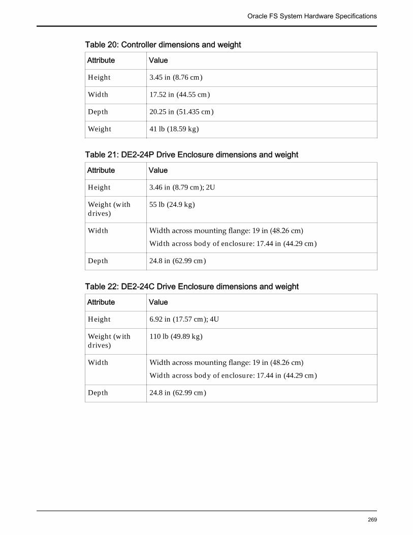
Table 20: Controller dimensions and weight
Attribute Value
Height 3.45 in (8.76 cm)
Width 17.52 in (44.55 cm)
Depth 20.25 in (51.435 cm)
Weight 41 lb (18.59 kg)
Table 21: DE2-24P Drive Enclosure dimensions and weight
Attribute Value
Height 3.46 in (8.79 cm); 2U
Weight (withdrives)
55 lb (24.9 kg)
Width Width across mounting flange: 19 in (48.26 cm)
Width across body of enclosure: 17.44 in (44.29 cm)
Depth 24.8 in (62.99 cm)
Table 22: DE2-24C Drive Enclosure dimensions and weight
Attribute Value
Height 6.92 in (17.57 cm); 4U
Weight (withdrives)
110 lb (49.89 kg)
Width Width across mounting flange: 19 in (48.26 cm)
Width across body of enclosure: 17.44 in (44.29 cm)
Depth 24.8 in (62.99 cm)
Oracle FS System Hardware Specifications
269
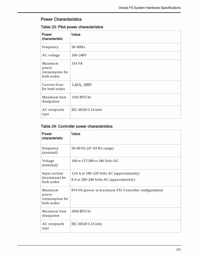
Power Characteristics
Table 23: Pilot power characteristics
Powercharacteristic
Value
Frequency 50–60Hz
AC voltage 100–240V
Maximumpowerconsumption forboth nodes
314 VA
Current drawfor both nodes
1.42A, 208V
Maximum heatdissipation
1102 BTU/hr
AC receptacletype
IEC 60320 C14 inlet
Table 24: Controller power characteristics
Powercharacteristic
Value
Frequency(nominal)
50–60 Hz (47–63 Hz range)
Voltage(nominal)
100 to 127/200 to 240 Volts AC
Input current(maximum) forboth nodes
13.6 A at 100–120 Volts AC (approximately)
8 A at 200–240 Volts AC (approximately)
Maximumpowerconsumption forboth nodes
874 VA (power at maximum FS1 Controller configuration)
Maximum heatdissipation
2830 BTU/hr
AC receptacletype
IEC 60320 C14 inlet
Oracle FS System Hardware Specifications
270
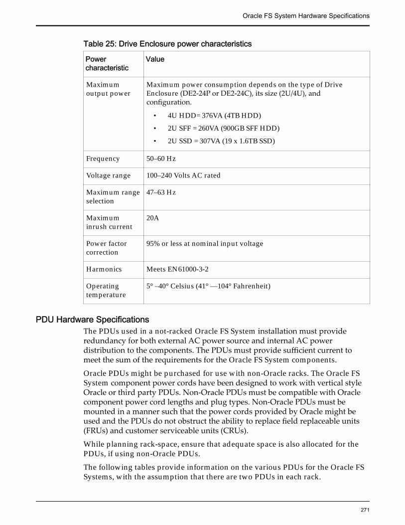
Table 25: Drive Enclosure power characteristics
Powercharacteristic
Value
Maximumoutput power
Maximum power consumption depends on the type of DriveEnclosure (DE2-24P or DE2-24C), its size (2U/4U), andconfiguration.
• 4U HDD= 376VA (4TB HDD)
• 2U SFF = 260VA (900GB SFF HDD)
• 2U SSD = 307VA (19 x 1.6TB SSD)
Frequency 50–60 Hz
Voltage range 100–240 Volts AC rated
Maximum rangeselection
47–63 Hz
Maximuminrush current
20A
Power factorcorrection
95% or less at nominal input voltage
Harmonics Meets EN61000-3-2
Operatingtemperature
5° –40° Celsius (41° —104° Fahrenheit)
PDU Hardware SpecificationsThe PDUs used in a not-racked Oracle FS System installation must provideredundancy for both external AC power source and internal AC powerdistribution to the components. The PDUs must provide sufficient current tomeet the sum of the requirements for the Oracle FS System components.
Oracle PDUs might be purchased for use with non-Oracle racks. The Oracle FSSystem component power cords have been designed to work with vertical styleOracle or third party PDUs. Non-Oracle PDUs must be compatible with Oraclecomponent power cord lengths and plug types. Non-Oracle PDUs must bemounted in a manner such that the power cords provided by Oracle might beused and the PDUs do not obstruct the ability to replace field replaceable units(FRUs) and customer serviceable units (CRUs).
While planning rack-space, ensure that adequate space is also allocated for thePDUs, if using non-Oracle PDUs.
The following tables provide information on the various PDUs for the Oracle FSSystems, with the assumption that there are two PDUs in each rack.
Oracle FS System Hardware Specifications
271
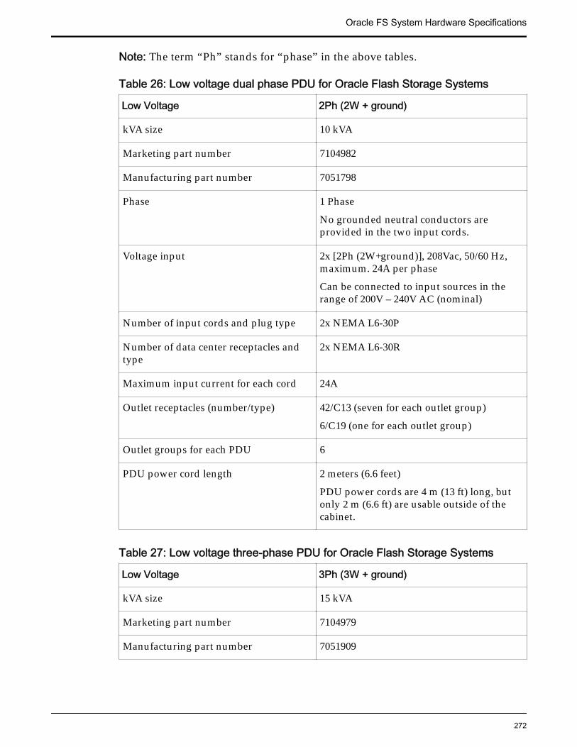
Note: The term “Ph” stands for “phase” in the above tables.
Table 26: Low voltage dual phase PDU for Oracle Flash Storage Systems
Low Voltage 2Ph (2W + ground)
kVA size 10 kVA
Marketing part number 7104982
Manufacturing part number 7051798
Phase 1 Phase
No grounded neutral conductors areprovided in the two input cords.
Voltage input 2x [2Ph (2W+ground)], 208Vac, 50/60 Hz,maximum. 24A per phase
Can be connected to input sources in therange of 200V – 240V AC (nominal)
Number of input cords and plug type 2x NEMA L6-30P
Number of data center receptacles andtype
2x NEMA L6-30R
Maximum input current for each cord 24A
Outlet receptacles (number/type) 42/C13 (seven for each outlet group)
6/C19 (one for each outlet group)
Outlet groups for each PDU 6
PDU power cord length 2 meters (6.6 feet)
PDU power cords are 4 m (13 ft) long, butonly 2 m (6.6 ft) are usable outside of thecabinet.
Table 27: Low voltage three-phase PDU for Oracle Flash Storage Systems
Low Voltage 3Ph (3W + ground)
kVA size 15 kVA
Marketing part number 7104979
Manufacturing part number 7051909
Oracle FS System Hardware Specifications
272
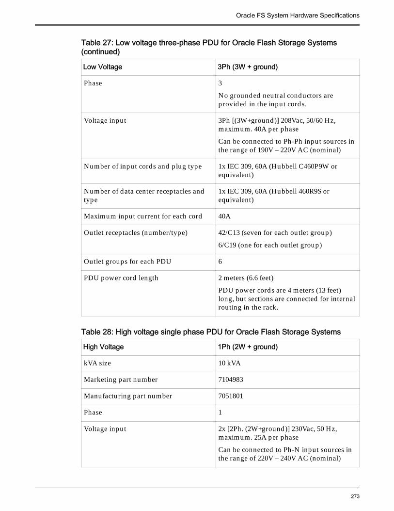
Table 27: Low voltage three-phase PDU for Oracle Flash Storage Systems(continued)
Low Voltage 3Ph (3W + ground)
Phase 3
No grounded neutral conductors areprovided in the input cords.
Voltage input 3Ph [(3W+ground)] 208Vac, 50/60 Hz,maximum. 40A per phase
Can be connected to Ph-Ph input sources inthe range of 190V – 220V AC (nominal)
Number of input cords and plug type 1x IEC 309, 60A (Hubbell C460P9W orequivalent)
Number of data center receptacles andtype
1x IEC 309, 60A (Hubbell 460R9S orequivalent)
Maximum input current for each cord 40A
Outlet receptacles (number/type) 42/C13 (seven for each outlet group)
6/C19 (one for each outlet group)
Outlet groups for each PDU 6
PDU power cord length 2 meters (6.6 feet)
PDU power cords are 4 meters (13 feet)long, but sections are connected for internalrouting in the rack.
Table 28: High voltage single phase PDU for Oracle Flash Storage Systems
High Voltage 1Ph (2W + ground)
kVA size 10 kVA
Marketing part number 7104983
Manufacturing part number 7051801
Phase 1
Voltage input 2x [2Ph. (2W+ground)] 230Vac, 50 Hz,maximum. 25A per phase
Can be connected to Ph-N input sources inthe range of 220V – 240V AC (nominal)
Oracle FS System Hardware Specifications
273
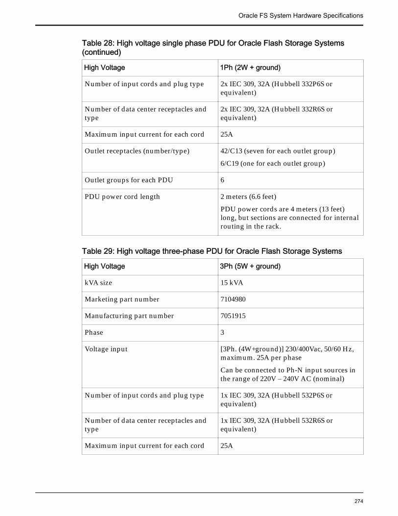
Table 28: High voltage single phase PDU for Oracle Flash Storage Systems(continued)
High Voltage 1Ph (2W + ground)
Number of input cords and plug type 2x IEC 309, 32A (Hubbell 332P6S orequivalent)
Number of data center receptacles andtype
2x IEC 309, 32A (Hubbell 332R6S orequivalent)
Maximum input current for each cord 25A
Outlet receptacles (number/type) 42/C13 (seven for each outlet group)
6/C19 (one for each outlet group)
Outlet groups for each PDU 6
PDU power cord length 2 meters (6.6 feet)
PDU power cords are 4 meters (13 feet)long, but sections are connected for internalrouting in the rack.
Table 29: High voltage three-phase PDU for Oracle Flash Storage Systems
High Voltage 3Ph (5W + ground)
kVA size 15 kVA
Marketing part number 7104980
Manufacturing part number 7051915
Phase 3
Voltage input [3Ph. (4W+ground)] 230/400Vac, 50/60 Hz,maximum. 25A per phase
Can be connected to Ph-N input sources inthe range of 220V – 240V AC (nominal)
Number of input cords and plug type 1x IEC 309, 32A (Hubbell 532P6S orequivalent)
Number of data center receptacles andtype
1x IEC 309, 32A (Hubbell 532R6S orequivalent)
Maximum input current for each cord 25A
Oracle FS System Hardware Specifications
274
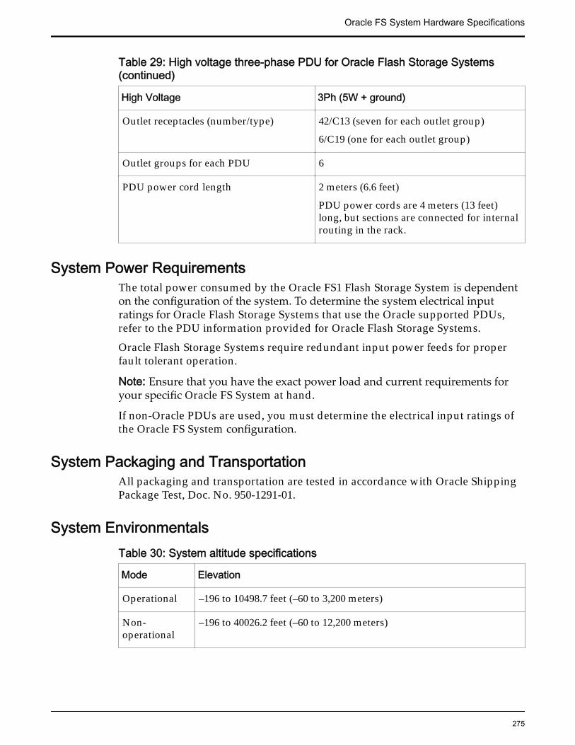
Table 29: High voltage three-phase PDU for Oracle Flash Storage Systems(continued)
High Voltage 3Ph (5W + ground)
Outlet receptacles (number/type) 42/C13 (seven for each outlet group)
6/C19 (one for each outlet group)
Outlet groups for each PDU 6
PDU power cord length 2 meters (6.6 feet)
PDU power cords are 4 meters (13 feet)long, but sections are connected for internalrouting in the rack.
System Power RequirementsThe total power consumed by the Oracle FS1 Flash Storage System is dependenton the configuration of the system. To determine the system electrical inputratings for Oracle Flash Storage Systems that use the Oracle supported PDUs,refer to the PDU information provided for Oracle Flash Storage Systems.
Oracle Flash Storage Systems require redundant input power feeds for properfault tolerant operation.
Note: Ensure that you have the exact power load and current requirements foryour specific Oracle FS System at hand.
If non-Oracle PDUs are used, you must determine the electrical input ratings ofthe Oracle FS System configuration.
System Packaging and TransportationAll packaging and transportation are tested in accordance with Oracle ShippingPackage Test, Doc. No. 950-1291-01.
System EnvironmentalsTable 30: System altitude specifications
Mode Elevation
Operational –196 to 10498.7 feet (–60 to 3,200 meters)
Non-operational
–196 to 40026.2 feet (–60 to 12,200 meters)
Oracle FS System Hardware Specifications
275
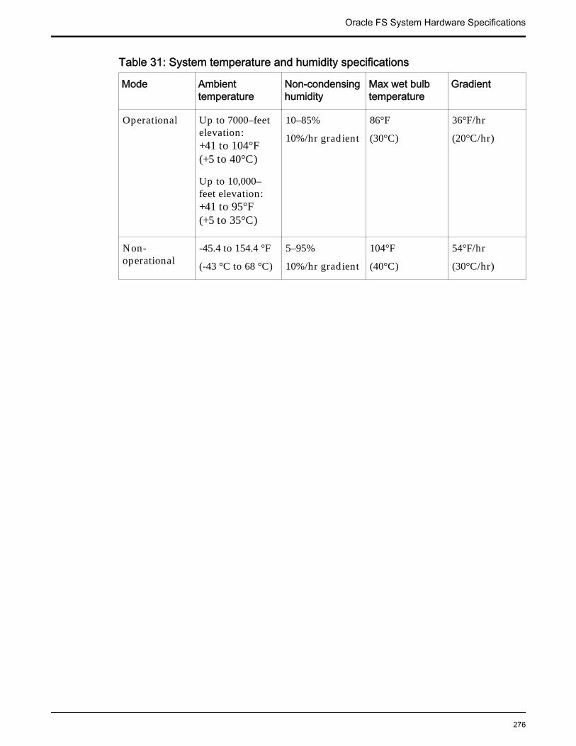
Table 31: System temperature and humidity specifications
Mode Ambienttemperature
Non-condensinghumidity
Max wet bulbtemperature
Gradient
Operational Up to 7000–feetelevation:+41 to 104°F(+5 to 40°C)
Up to 10,000–feet elevation:+41 to 95°F(+5 to 35°C)
10–85%
10%/hr gradient
86°F
(30°C)
36°F/hr
(20°C/hr)
Non-operational
-45.4 to 154.4 °F
(-43 °C to 68 °C)
5–95%
10%/hr gradient
104°F
(40°C)
54°F/hr
(30°C/hr)
Oracle FS System Hardware Specifications
276
APPENDIX B
Oracle FS System LED Status
Oracle FS System LEDsAn Oracle FS System includes LEDs to indicate the status of the hardwarecomponents. To restore reliability to the Oracle FS System, locate the specificfailed component so that you can replace it. Hardware LED configuration helpsyou identify the failed component.
Important: If you cannot locate the hardware component that must be replaced,contact Oracle Customer Support.
The Guided Maintenance feature of the Oracle FS System Manager triggers thechassis with the failed component to blink, or it triggers all of the other chassis toblink, except for the one with the failed component. This blinking pattern helpsyou to identify component status.
Note: LED interpretations in this appendix apply to a system after it has beenpowered on.
Related LinksController LED IndicatorsDrive Enclosure LED IndicatorsPilot LED IndicatorsPilot Drive LED IndicatorsPilot Fan LED IndicatorsPilot Port LED IndicatorsPilot Motherboard LED IndicatorsPilot Power Supply LED Indicators
Controller LED IndicatorsThe LED alarm assembly is a high-level status indicator of the Controller andController components. Use these diagnostic LEDs to determine if a componenthas failed in the Controller. The LED alarm assembly also includes a powerbutton to power on the Controller. Besides, the LED alarm assembly there is theController Identification Display (CID) that identifies the Controller by itsnumeric identifier.
The following figure shows the front display panel of the LED alarm assemblyon the Controller:
277
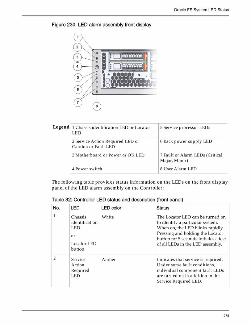
Figure 230: LED alarm assembly front display
Legend 1 Chassis identification LED or LocatorLED
5 Service processor LEDs
2 Service Action Required LED orCaution or Fault LED
6 Back power supply LED
3 Motherboard or Power or OK LED 7 Fault or Alarm LEDs (Critical,Major, Minor)
4 Power switch 8 User Alarm LED
The following table provides status information on the LEDs on the front displaypanel of the LED alarm assembly on the Controller:
Table 32: Controller LED status and description (front panel)No. LED LED color Status1 Chassis
identificationLED
or
Locator LEDbutton
White The Locator LED can be turned onto identify a particular system.When on, the LED blinks rapidly.Pressing and holding the Locatorbutton for 5 seconds initiates a testof all LEDs in the LED assembly.
2 ServiceActionRequiredLED
Amber Indicates that service is required.Under some fault conditions,individual component fault LEDsare turned on in addition to theService Required LED.
Oracle FS System LED Status
278
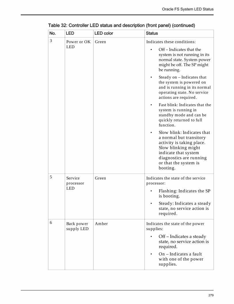
Table 32: Controller LED status and description (front panel) (continued)No. LED LED color Status3 Power or OK
LEDGreen Indicates these conditions:
• Off – Indicates that thesystem is not running in itsnormal state. System powermight be off. The SP mightbe running.
• Steady on – Indicates thatthe system is powered onand is running in its normaloperating state. No serviceactions are required.
• Fast blink: Indicates that thesystem is running instandby mode and can bequickly returned to fullfunction.
• Slow blink: Indicates thata normal but transitoryactivity is taking place.Slow blinking mightindicate that systemdiagnostics are runningor that the system isbooting.
5 ServiceprocessorLED
Green Indicates the state of the serviceprocessor:
• Flashing: Indicates the SPis booting.
• Steady: Indicates a steadystate, no service action isrequired.
6 Back powersupply LED
Amber Indicates the state of the powersupplies:
• Off – Indicates a steadystate, no service action isrequired.
• On – Indicates a faultwith one of the powersupplies.
Oracle FS System LED Status
279
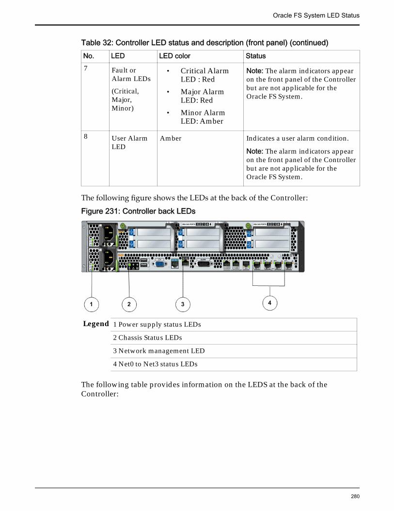
Table 32: Controller LED status and description (front panel) (continued)No. LED LED color Status7 Fault or
Alarm LEDs
(Critical,Major,Minor)
• Critical AlarmLED : Red
• Major AlarmLED: Red
• Minor AlarmLED: Amber
Note: The alarm indicators appearon the front panel of the Controllerbut are not applicable for theOracle FS System.
8 User AlarmLED
Amber Indicates a user alarm condition.
Note: The alarm indicators appearon the front panel of the Controllerbut are not applicable for theOracle FS System.
The following figure shows the LEDs at the back of the Controller:
Figure 231: Controller back LEDs
Legend 1 Power supply status LEDs
2 Chassis Status LEDs
3 Network management LED
4 Net0 to Net3 status LEDs
The following table provides information on the LEDS at the back of theController:
Oracle FS System LED Status
280
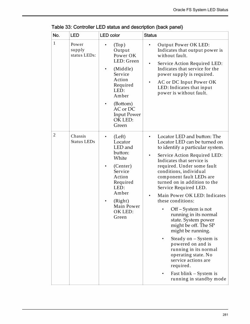
Table 33: Controller LED status and description (back panel)No. LED LED color Status1 Power
supplystatus LEDs:
• (Top)OutputPower OKLED: Green
• (Middle)ServiceActionRequiredLED:Amber
• (Bottom)AC or DCInput PowerOK LED:Green
• Output Power OK LED:Indicates that output power iswithout fault.
• Service Action Required LED:Indicates that service for thepower supply is required.
• AC or DC Input Power OKLED: Indicates that inputpower is without fault.
2 ChassisStatus LEDs
• (Left)LocatorLED andbutton:White
• (Center)ServiceActionRequiredLED:Amber
• (Right)Main PowerOK LED:Green
• Locator LED and button: TheLocator LED can be turned onto identify a particular system.
• Service Action Required LED:Indicates that service isrequired. Under some faultconditions, individualcomponent fault LEDs areturned on in addition to theService Required LED.
• Main Power OK LED: Indicatesthese conditions:
• Off – System is notrunning in its normalstate. System powermight be off. The SPmight be running.
• Steady on – System ispowered on and isrunning in its normaloperating state. Noservice actions arerequired.
• Fast blink – System isrunning in standby mode
Oracle FS System LED Status
281
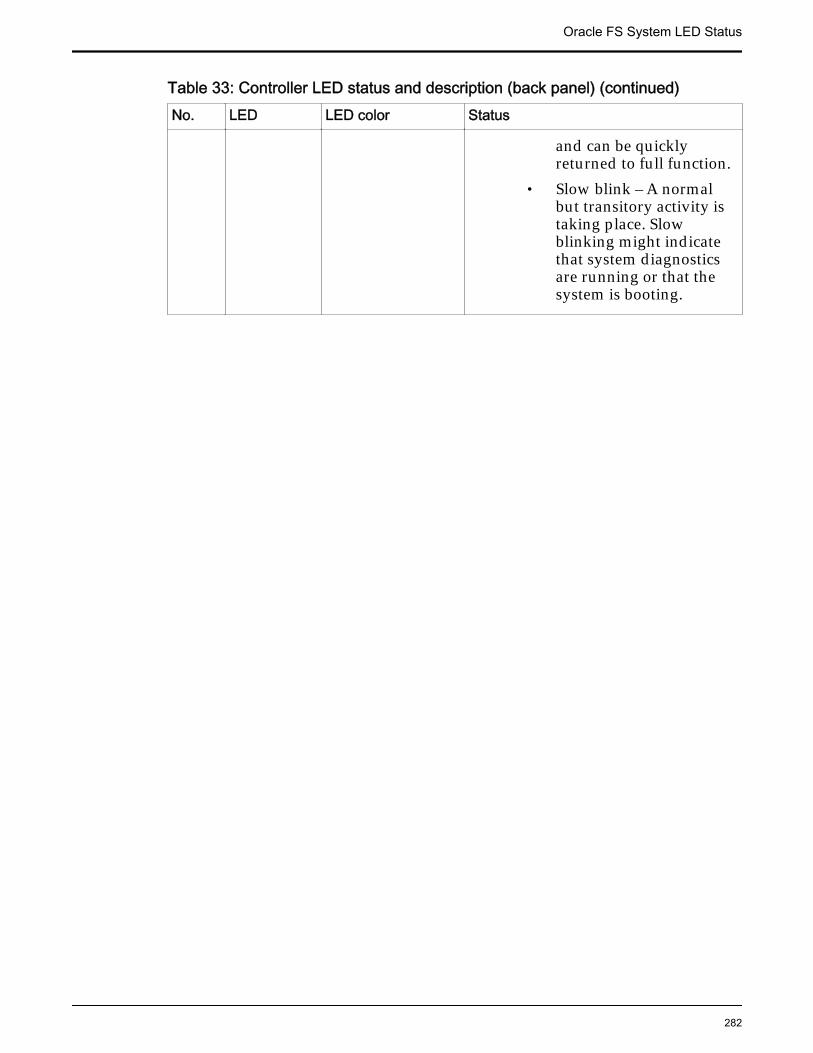
Table 33: Controller LED status and description (back panel) (continued)No. LED LED color Status
and can be quicklyreturned to full function.
• Slow blink – A normalbut transitory activity istaking place. Slowblinking might indicatethat system diagnosticsare running or that thesystem is booting.
Oracle FS System LED Status
282
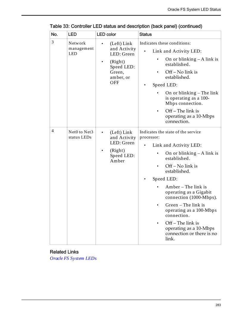
Table 33: Controller LED status and description (back panel) (continued)No. LED LED color Status3 Network
managementLED
• (Left) Linkand ActivityLED: Green
• (Right)Speed LED:Green,amber, orOFF
Indicates these conditions:
• Link and Activity LED:• On or blinking – A link is
established.• Off – No link is
established.• Speed LED:
• On or blinking – The linkis operating as a 100-Mbps connection.
• Off – The link isoperating as a 10-Mbpsconnection.
4 Net0 to Net3status LEDs
• (Left) Linkand ActivityLED: Green
• (Right)Speed LED:Amber
Indicates the state of the serviceprocessor:
• Link and Activity LED:• On or blinking – A link is
established.• Off – No link is
established.• Speed LED:
• Amber – The link isoperating as a Gigabitconnection (1000-Mbps).
• Green – The link isoperating as a 100-Mbpsconnection.
• Off – The link isoperating as a 10-Mbpsconnection or there is nolink.
Related LinksOracle FS System LEDs
Oracle FS System LED Status
283
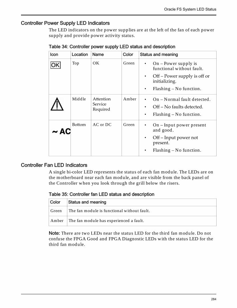
Controller Power Supply LED IndicatorsThe LED indicators on the power supplies are at the left of the fan of each powersupply and provide power activity status.
Table 34: Controller power supply LED status and descriptionIcon Location Name Color Status and meaning
Top OK Green • On – Power supply isfunctional without fault.
• Off – Power supply is off orinitializing.
• Flashing – No function.
Middle AttentionServiceRequired
Amber • On – Normal fault detected.• Off – No faults detected.• Flashing – No function.
Bottom AC or DC Green • On – Input power presentand good.
• Off – Input power notpresent.
• Flashing – No function.
Controller Fan LED IndicatorsA single bi-color LED represents the status of each fan module. The LEDs are onthe motherboard near each fan module, and are visible from the back panel ofthe Controller when you look through the grill below the risers.
Table 35: Controller fan LED status and descriptionColor Status and meaning
Green The fan module is functional without fault.
Amber The fan module has experienced a fault.
Note: There are two LEDs near the status LED for the third fan module. Do notconfuse the FPGA Good and FPGA Diagnostic LEDs with the status LED for thethird fan module.
Oracle FS System LED Status
284

Controller ESM LED IndicatorsThree LEDs represent the status of each energy storage module (ESM). The LEDsare above the release button of each drive.
Figure 232: Controller drive LEDs
Legend 1 Ready to Remove LED
2 Attention Service Required LED
3 OK/Activity LED
4 Power switch
This following table describes the functionality of the ESM LEDs:
Oracle FS System LED Status
285
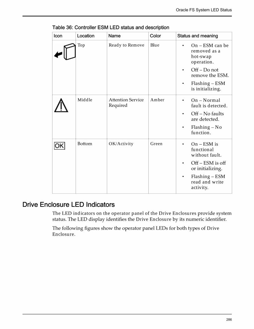
Table 36: Controller ESM LED status and descriptionIcon Location Name Color Status and meaning
Top Ready to Remove Blue • On – ESM can beremoved as ahot-swapoperation.
• Off – Do notremove the ESM.
• Flashing – ESMis initializing.
Middle Attention ServiceRequired
Amber • On – Normalfault is detected.
• Off – No faultsare detected.
• Flashing – Nofunction.
Bottom OK/Activity Green • On – ESM isfunctionalwithout fault.
• Off – ESM is offor initializing.
• Flashing – ESMread and writeactivity.
Drive Enclosure LED IndicatorsThe LED indicators on the operator panel of the Drive Enclosures provide systemstatus. The LED display identifies the Drive Enclosure by its numeric identifier.
The following figures show the operator panel LEDs for both types of DriveEnclosure.
Oracle FS System LED Status
286
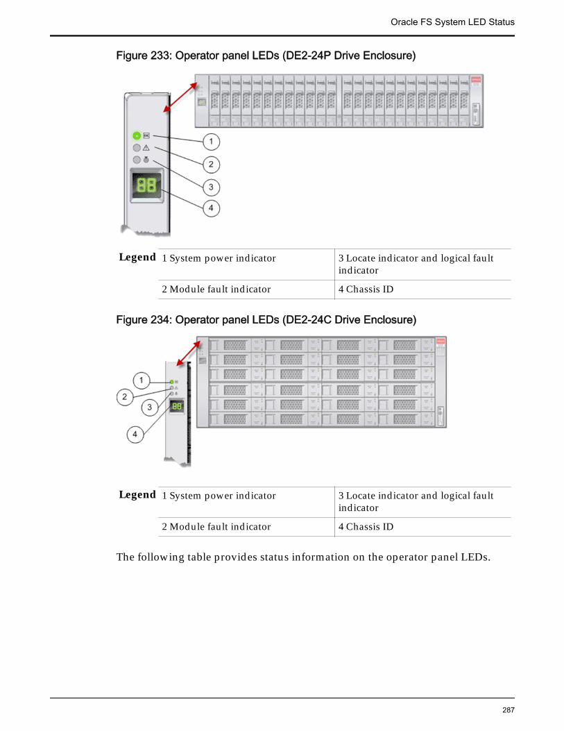
Figure 233: Operator panel LEDs (DE2-24P Drive Enclosure)
Legend 1 System power indicator 3 Locate indicator and logical faultindicator
2 Module fault indicator 4 Chassis ID
Figure 234: Operator panel LEDs (DE2-24C Drive Enclosure)
Legend 1 System power indicator 3 Locate indicator and logical faultindicator
2 Module fault indicator 4 Chassis ID
The following table provides status information on the operator panel LEDs.
Oracle FS System LED Status
287
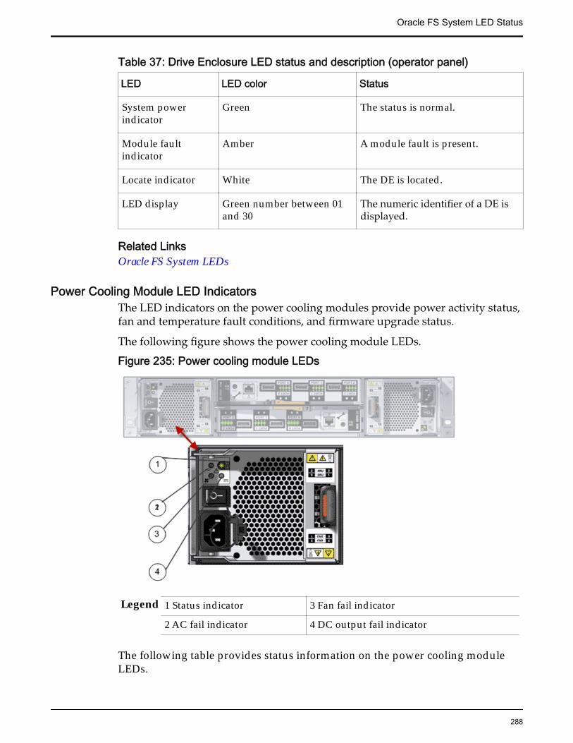
Table 37: Drive Enclosure LED status and description (operator panel)
LED LED color Status
System powerindicator
Green The status is normal.
Module faultindicator
Amber A module fault is present.
Locate indicator White The DE is located.
LED display Green number between 01and 30
The numeric identifier of a DE isdisplayed.
Related LinksOracle FS System LEDs
Power Cooling Module LED IndicatorsThe LED indicators on the power cooling modules provide power activity status,fan and temperature fault conditions, and firmware upgrade status.
The following figure shows the power cooling module LEDs.
Figure 235: Power cooling module LEDs
Legend 1 Status indicator 3 Fan fail indicator
2 AC fail indicator 4 DC output fail indicator
The following table provides status information on the power cooling moduleLEDs.
Oracle FS System LED Status
288
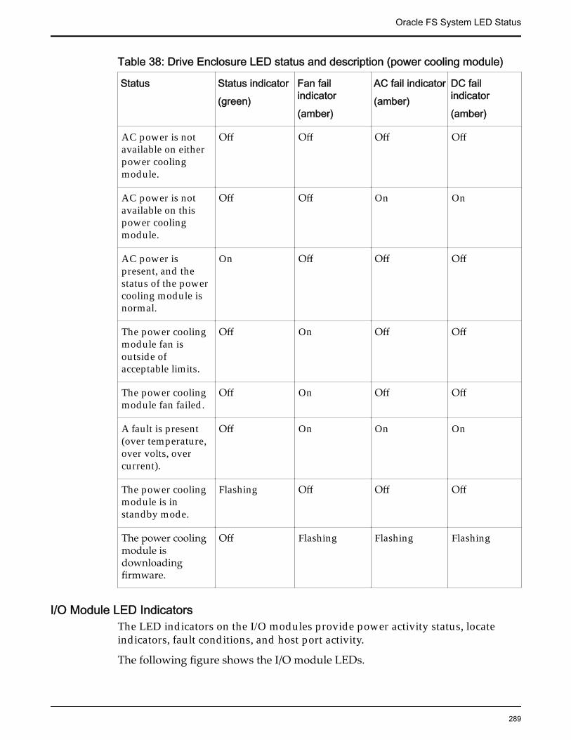
Table 38: Drive Enclosure LED status and description (power cooling module)
Status Status indicator(green)
Fan failindicator(amber)
AC fail indicator(amber)
DC failindicator(amber)
AC power is notavailable on eitherpower coolingmodule.
Off Off Off Off
AC power is notavailable on thispower coolingmodule.
Off Off On On
AC power ispresent, and thestatus of the powercooling module isnormal.
On Off Off Off
The power coolingmodule fan isoutside ofacceptable limits.
Off On Off Off
The power coolingmodule fan failed.
Off On Off Off
A fault is present(over temperature,over volts, overcurrent).
Off On On On
The power coolingmodule is instandby mode.
Flashing Off Off Off
The power coolingmodule isdownloadingfirmware.
Off Flashing Flashing Flashing
I/O Module LED IndicatorsThe LED indicators on the I/O modules provide power activity status, locateindicators, fault conditions, and host port activity.
The following figure shows the I/O module LEDs.
Oracle FS System LED Status
289
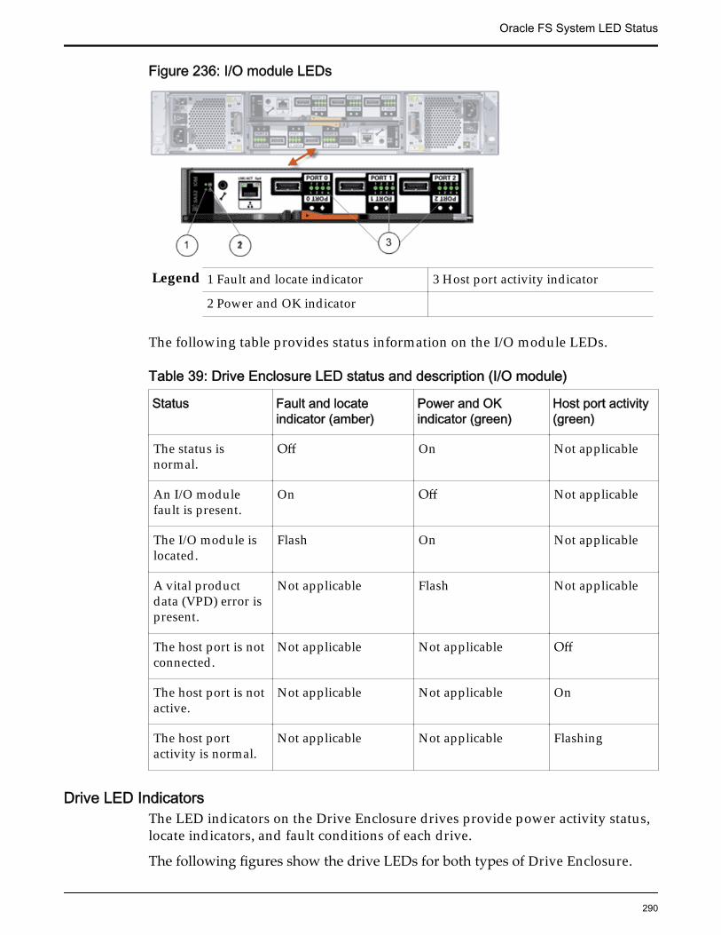
Figure 236: I/O module LEDs
Legend 1 Fault and locate indicator 3 Host port activity indicator
2 Power and OK indicator
The following table provides status information on the I/O module LEDs.
Table 39: Drive Enclosure LED status and description (I/O module)
Status Fault and locateindicator (amber)
Power and OKindicator (green)
Host port activity(green)
The status isnormal.
Off On Not applicable
An I/O modulefault is present.
On Off Not applicable
The I/O module islocated.
Flash On Not applicable
A vital productdata (VPD) error ispresent.
Not applicable Flash Not applicable
The host port is notconnected.
Not applicable Not applicable Off
The host port is notactive.
Not applicable Not applicable On
The host portactivity is normal.
Not applicable Not applicable Flashing
Drive LED IndicatorsThe LED indicators on the Drive Enclosure drives provide power activity status,locate indicators, and fault conditions of each drive.
The following figures show the drive LEDs for both types of Drive Enclosure.
Oracle FS System LED Status
290
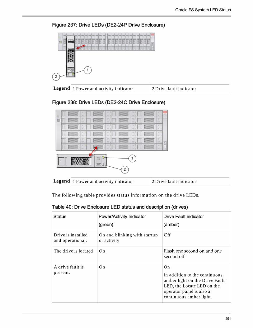
Figure 237: Drive LEDs (DE2-24P Drive Enclosure)
Legend 1 Power and activity indicator 2 Drive fault indicator
Figure 238: Drive LEDs (DE2-24C Drive Enclosure)
Legend 1 Power and activity indicator 2 Drive fault indicator
The following table provides status information on the drive LEDs.
Table 40: Drive Enclosure LED status and description (drives)
Status Power/Activity Indicator(green)
Drive Fault indicator(amber)
Drive is installedand operational.
On and blinking with startupor activity
Off
The drive is located. On Flash one second on and onesecond off
A drive fault ispresent.
On On
In addition to the continuousamber light on the Drive FaultLED, the Locate LED on theoperator panel is also acontinuous amber light.
Oracle FS System LED Status
291
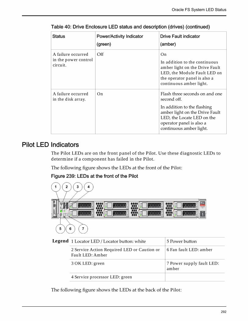
Table 40: Drive Enclosure LED status and description (drives) (continued)
Status Power/Activity Indicator(green)
Drive Fault indicator(amber)
A failure occurredin the power controlcircuit.
Off On
In addition to the continuousamber light on the Drive FaultLED, the Module Fault LED onthe operator panel is also acontinuous amber light.
A failure occurredin the disk array.
On Flash three seconds on and onesecond off.
In addition to the flashingamber light on the Drive FaultLED, the Locate LED on theoperator panel is also acontinuous amber light.
Pilot LED IndicatorsThe Pilot LEDs are on the front panel of the Pilot. Use these diagnostic LEDs todetermine if a component has failed in the Pilot.
The following figure shows the LEDs at the front of the Pilot:
Figure 239: LEDs at the front of the Pilot
Legend 1 Locator LED / Locator button: white 5 Power button
2 Service Action Required LED or Caution orFault LED: Amber
6 Fan fault LED: amber
3 OK LED: green 7 Power supply fault LED:amber
4 Service processor LED: green
The following figure shows the LEDs at the back of the Pilot:
Oracle FS System LED Status
292
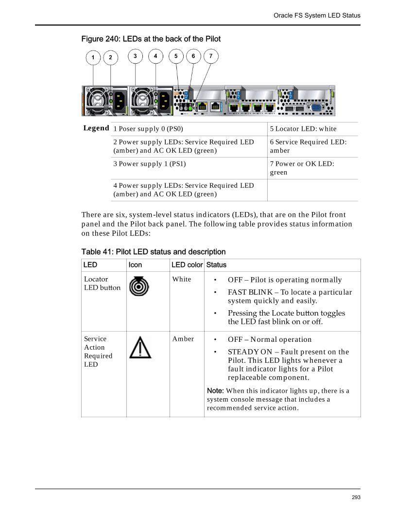
Figure 240: LEDs at the back of the Pilot
Legend 1 Poser supply 0 (PS0) 5 Locator LED: white
2 Power supply LEDs: Service Required LED(amber) and AC OK LED (green)
6 Service Required LED:amber
3 Power supply 1 (PS1) 7 Power or OK LED:green
4 Power supply LEDs: Service Required LED(amber) and AC OK LED (green)
There are six, system-level status indicators (LEDs), that are on the Pilot frontpanel and the Pilot back panel. The following table provides status informationon these Pilot LEDs:
Table 41: Pilot LED status and descriptionLED Icon LED color Status
LocatorLED button
White • OFF – Pilot is operating normally• FAST BLINK – To locate a particular
system quickly and easily.• Pressing the Locate button toggles
the LED fast blink on or off.
ServiceActionRequiredLED
Amber • OFF – Normal operation• STEADY ON – Fault present on the
Pilot. This LED lights whenever afault indicator lights for a Pilotreplaceable component.
Note: When this indicator lights up, there is asystem console message that includes arecommended service action.
Oracle FS System LED Status
293
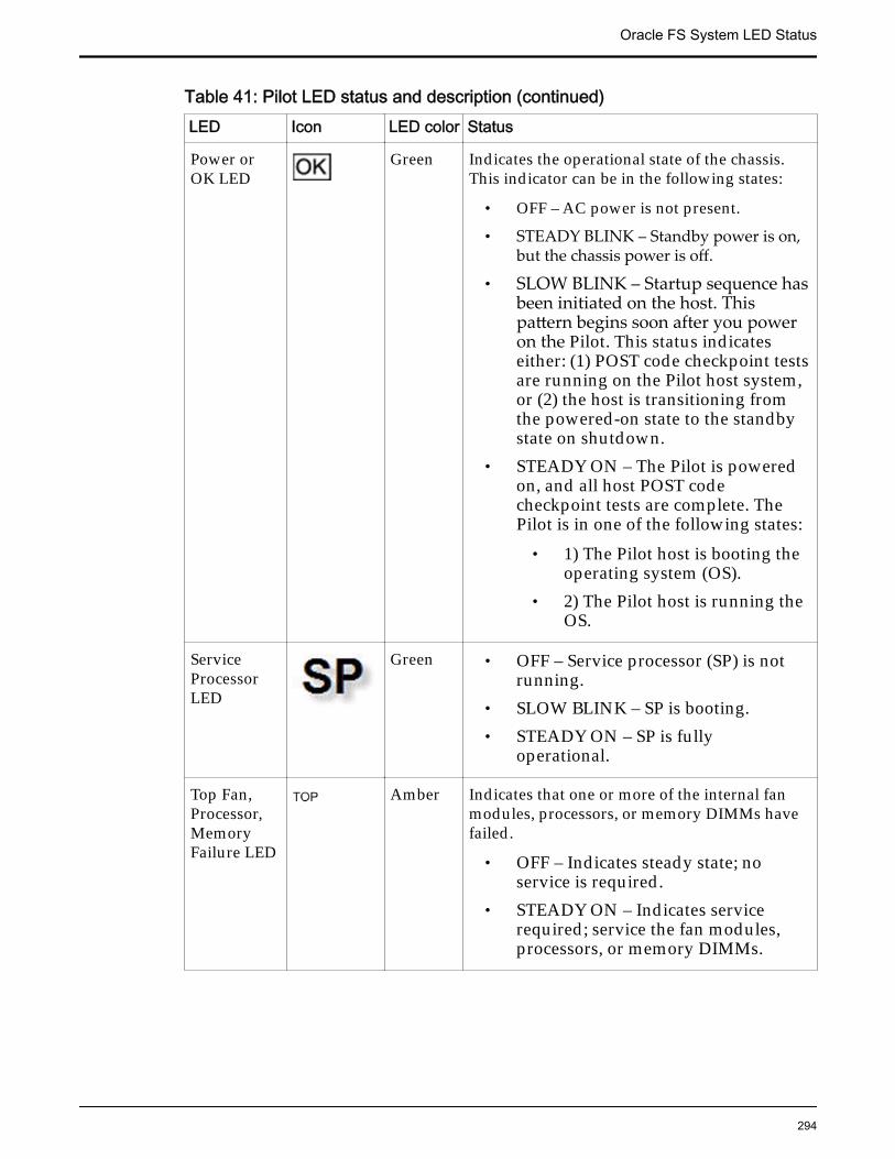
Table 41: Pilot LED status and description (continued)LED Icon LED color Status
Power orOK LED
Green Indicates the operational state of the chassis.This indicator can be in the following states:
• OFF – AC power is not present.
• STEADY BLINK – Standby power is on,but the chassis power is off.
• SLOW BLINK – Startup sequence hasbeen initiated on the host. Thispattern begins soon after you poweron the Pilot. This status indicateseither: (1) POST code checkpoint testsare running on the Pilot host system,or (2) the host is transitioning fromthe powered-on state to the standbystate on shutdown.
• STEADY ON – The Pilot is poweredon, and all host POST codecheckpoint tests are complete. ThePilot is in one of the following states:
• 1) The Pilot host is booting theoperating system (OS).
• 2) The Pilot host is running theOS.
ServiceProcessorLED
Green • OFF – Service processor (SP) is notrunning.
• SLOW BLINK – SP is booting.• STEADY ON – SP is fully
operational.
Top Fan,Processor,MemoryFailure LED
Amber Indicates that one or more of the internal fanmodules, processors, or memory DIMMs havefailed.
• OFF – Indicates steady state; noservice is required.
• STEADY ON – Indicates servicerequired; service the fan modules,processors, or memory DIMMs.
Oracle FS System LED Status
294
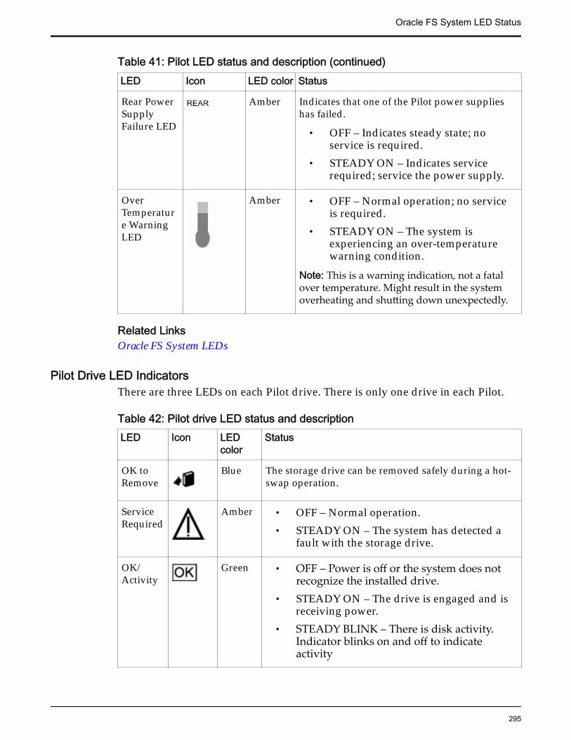
Table 41: Pilot LED status and description (continued)LED Icon LED color Status
Rear PowerSupplyFailure LED
Amber Indicates that one of the Pilot power supplieshas failed.
• OFF – Indicates steady state; noservice is required.
• STEADY ON – Indicates servicerequired; service the power supply.
OverTemperature WarningLED
Amber • OFF – Normal operation; no serviceis required.
• STEADY ON – The system isexperiencing an over-temperaturewarning condition.
Note: This is a warning indication, not a fatalover temperature. Might result in the systemoverheating and shutting down unexpectedly.
Related LinksOracle FS System LEDs
Pilot Drive LED IndicatorsThere are three LEDs on each Pilot drive. There is only one drive in each Pilot.
Table 42: Pilot drive LED status and descriptionLED Icon LED
colorStatus
OK toRemove
Blue The storage drive can be removed safely during a hot-swap operation.
ServiceRequired
Amber • OFF – Normal operation.• STEADY ON – The system has detected a
fault with the storage drive.
OK/Activity
Green • OFF – Power is off or the system does notrecognize the installed drive.
• STEADY ON – The drive is engaged and isreceiving power.
• STEADY BLINK – There is disk activity.Indicator blinks on and off to indicateactivity
Oracle FS System LED Status
295
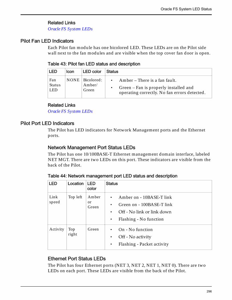
Related LinksOracle FS System LEDs
Pilot Fan LED IndicatorsEach Pilot fan module has one bicolored LED. These LEDs are on the Pilot sidewall next to the fan modules and are visible when the top cover fan door is open.
Table 43: Pilot fan LED status and descriptionLED Icon LED color Status
FanStatusLED
NONE Bicolored:Amber/Green
• Amber – There is a fan fault.• Green – Fan is properly installed and
operating correctly. No fan errors detected.
Related LinksOracle FS System LEDs
Pilot Port LED IndicatorsThe Pilot has LED indicators for Network Management ports and the Ethernetports.
Network Management Port Status LEDsThe Pilot has one 10/100BASE-T Ethernet management domain interface, labeledNET MGT. There are two LEDs on this port. These indicators are visible from theback of the Pilot.
Table 44: Network management port LED status and descriptionLED Location LED
colorStatus
Linkspeed
Top left AmberorGreen
• Amber on - 10BASE-T link• Green on - 100BASE-T link• Off - No link or link down• Flashing - No function
Activity Topright
Green • On - No function• Off - No activity• Flashing - Packet activity
Ethernet Port Status LEDsThe Pilot has four Ethernet ports (NET 3, NET 2, NET 1, NET 0). There are twoLEDs on each port. These LEDs are visible from the back of the Pilot.
Oracle FS System LED Status
296
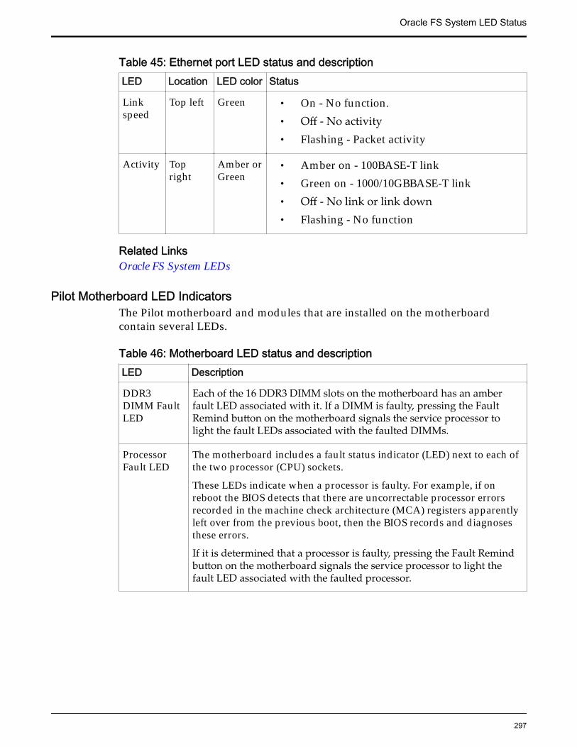
Table 45: Ethernet port LED status and descriptionLED Location LED color Status
Linkspeed
Top left Green • On - No function.• Off - No activity• Flashing - Packet activity
Activity Topright
Amber orGreen
• Amber on - 100BASE-T link• Green on - 1000/10GBBASE-T link• Off - No link or link down• Flashing - No function
Related LinksOracle FS System LEDs
Pilot Motherboard LED IndicatorsThe Pilot motherboard and modules that are installed on the motherboardcontain several LEDs.
Table 46: Motherboard LED status and descriptionLED Description
DDR3DIMM FaultLED
Each of the 16 DDR3 DIMM slots on the motherboard has an amberfault LED associated with it. If a DIMM is faulty, pressing the FaultRemind button on the motherboard signals the service processor tolight the fault LEDs associated with the faulted DIMMs.
ProcessorFault LED
The motherboard includes a fault status indicator (LED) next to each ofthe two processor (CPU) sockets.
These LEDs indicate when a processor is faulty. For example, if onreboot the BIOS detects that there are uncorrectable processor errorsrecorded in the machine check architecture (MCA) registers apparentlyleft over from the previous boot, then the BIOS records and diagnosesthese errors.
If it is determined that a processor is faulty, pressing the Fault Remindbutton on the motherboard signals the service processor to light thefault LED associated with the faulted processor.
Oracle FS System LED Status
297
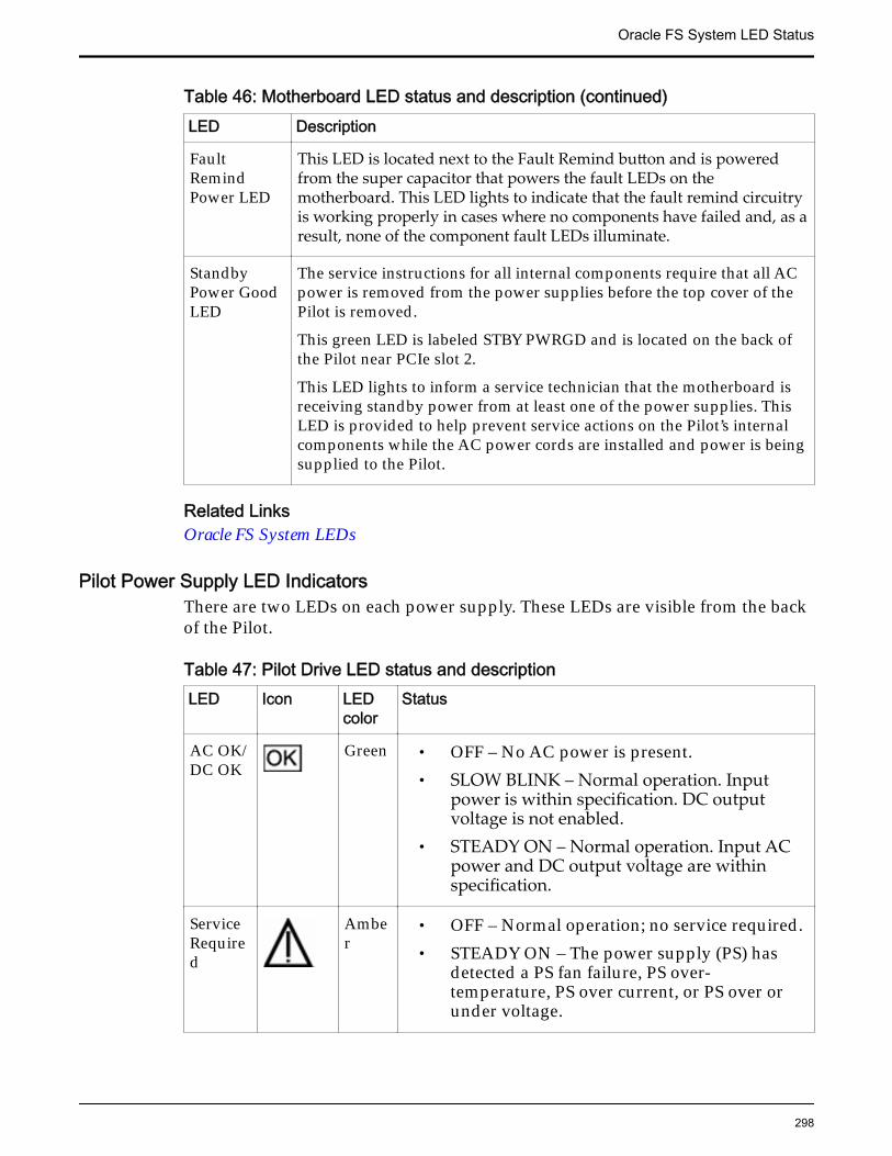
Table 46: Motherboard LED status and description (continued)LED Description
FaultRemindPower LED
This LED is located next to the Fault Remind button and is poweredfrom the super capacitor that powers the fault LEDs on themotherboard. This LED lights to indicate that the fault remind circuitryis working properly in cases where no components have failed and, as aresult, none of the component fault LEDs illuminate.
StandbyPower GoodLED
The service instructions for all internal components require that all ACpower is removed from the power supplies before the top cover of thePilot is removed.
This green LED is labeled STBY PWRGD and is located on the back ofthe Pilot near PCIe slot 2.
This LED lights to inform a service technician that the motherboard isreceiving standby power from at least one of the power supplies. ThisLED is provided to help prevent service actions on the Pilot’s internalcomponents while the AC power cords are installed and power is beingsupplied to the Pilot.
Related LinksOracle FS System LEDs
Pilot Power Supply LED IndicatorsThere are two LEDs on each power supply. These LEDs are visible from the backof the Pilot.
Table 47: Pilot Drive LED status and descriptionLED Icon LED
colorStatus
AC OK/DC OK
Green • OFF – No AC power is present.• SLOW BLINK – Normal operation. Input
power is within specification. DC outputvoltage is not enabled.
• STEADY ON – Normal operation. Input ACpower and DC output voltage are withinspecification.
ServiceRequired
Amber
• OFF – Normal operation; no service required.• STEADY ON – The power supply (PS) has
detected a PS fan failure, PS over-temperature, PS over current, or PS over orunder voltage.
Oracle FS System LED Status
298

Related LinksOracle FS System LEDs
Oracle FS System LED Status
299
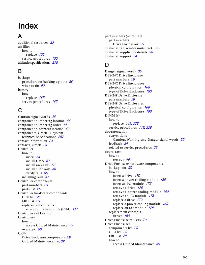
IndexAadditional resources 23air filter
how toreplace 100
service procedures 100altitude specifications 275
Bbackups
procedure for backing up data 50when to do 50
batteryhow to
replace 187service procedures 187
CCaution signal words 35component numbering location 44component numbering order 44component placement location 42components, Oracle FS system
technical specifications 267contact information 24contacts, Oracle 24Controller
how toinsert 64install CMA 61install rack rails 53install slide rails 56verify rails 65
installing rails 51Controller components
part numbers 25parts list 25
Controller hardware componentsCRU list 25FRU list 25replacement concepts
energy storage module (ESM) 117Controller rail kits 52Controllers
how toaccess Guided Maintenance 39
overview 98CRUs
Drive Enclosure components 29Guided Maintenance 38, 39
part numbers (continued)part numbers
Drive Enclosures 29customer replaceable units, see CRUscustomer supplied materials 36customer support 24
DDanger signal words 35DE2-24C Drive Enclosure
part numbers 29DE2-24C Drive Enclosures
physical configuration 166type of Drive Enclosure 166
DE2-24P Drive Enclosurepart numbers 29
DE2-24P Drive Enclosuresphysical configuration 166type of Drive Enclosure 166
DIMM (s)how to
replace 149, 228service procedures 149, 228
documentationconventions
Caution, Warning, and Danger signal words 35feedback 24related to service procedures 23
doors, rackhow to
remove 49Drive Enclosure hardware components
backups for 50how to
insert a drive 170insert a power cooling module 180insert an I/O module 175remove a drive 170remove a power cooling module 180remove an I/O module 175replace a drive 170replace a power cooling module 180replace an I/O module 175
replacement conceptsdrives 168
Drive Enclosure rail kits 70Drive Enclosures
components list 29CRU list 29FRU list 29how to
access Guided Maintenance 39
300
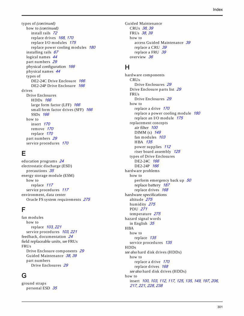
types of (continued)how to (continued)
install rails 72replace drives 168, 170replace I/O modules 175replace power cooling modules 180
installing rails 67logical names 44part numbers 29physical configuration 166physical names 44types of
DE2-24C Drive Enclosure 166DE2-24P Drive Enclosure 166
drivesDrive Enclosures
HDDs 166large form factor (LFF) 166small form factor drives (SFF) 166SSDs 166
how toinsert 170remove 170replace 170
part numbers 29service procedures 170
Eeducation programs 24electrostatic discharge (ESD)
precautions 35energy storage module (ESM)
how toreplace 117
service procedures 117environment, data center
Oracle FS system requirements 275
Ffan modules
how toreplace 103, 221
service procedures 103, 221feedback, documentation 24field replaceable units, see FRUsFRUs
Drive Enclosure components 29Guided Maintenance 38, 39part numbers
Drive Enclosures 29
Gground straps
personal ESD 35
Guided MaintenanceCRUs 38, 39FRUs 38, 39how to
access Guided Maintenance 39replace a CRU 39replace a FRU 39
overview 36
Hhardware components
CRUsDrive Enclosures 29
Drive Enclosure parts list 29FRUs
Drive Enclosures 29how to
replace a drive 170replace a power cooling module 180replace an I/O module 175
replacement conceptsair filter 100DIMM (s) 149fan modules 103HBA 135power supplies 112riser board assembly 125
types of Drive EnclosuresDE2-24C 166DE2-24P 166
hardware problemshow to
perform emergency back up 50replace battery 187replace drives 168
hardware specificationsaltitude 275humidity 275PDU 271temperature 275
hazard signal wordsin English 35
HBAhow to
replace 135service procedures 135
HDDssee also hard disk drives (HDDs)
how toreplace a drive 170replace drives 168
see also hard disk drives (HDDs)how to
insert 100, 103, 112, 117, 125, 135, 149, 197, 206,217, 221, 228, 238
Index
301
how to (continued)remove 100, 103, 112, 117, 125, 135, 149, 197, 206,217, 221, 228, 238
humidity specifications 275
II/O modules
how toinsert 175remove 175replace 175
part numbers 29service procedures 175
insertair filter 100DIMM (s) 149, 228drives 170energy storage module (ESM) 117fan module 103, 221HBA 135I/O modules 175Pilot chassis 238power cooling modules 180power supplies 112, 217riser board assembly 125, 206SAS HBA 197
installation procedurestools, required 36
KKey Identity Properties (KIP) 35, 98
Llarge form factor (LFF) drives, see drivesLED status 277
Nnotice conventions, safety 35
Oonline help 24Oracle documentation 24Oracle FS system
component numberinglocation 44order 44
component placementlocation 42
hardware specifications 267Oracle FS System
Drive Enclosuresreplace a drive 170replace a power cooling module 180
how to (continued)Drive Enclosures (continued)
replace an I/O module 175how to
back up data 51prepare the rack 48
LED status indicators 277power cycling 51
Oracle FS System ManagerGuided Maintenance 36
Oracle FS SystemsControllers
overview 98Pilots, overview 187
Oracle Help Center (OHC) 24Oracle racks
how toremove rack doors 49
Ppanels, rack
how toremove 49
part numbersController components 25DE2-24C Drive Enclosure chassis 29DE2-24P Drive Enclosure chassis 29drives 29I/O modules 29Pilot components 32power cooling modules 29
parts listController components 25Pilot components 32
PDUshardware specifications 271
Pilothow to
insert 94install CMA 93install rack rails 89install slide rails 92verify rails 96
Pilot chassishow to
replace 238service procedures 238
Pilot componentspart numbers 32parts list 32
Pilot hardware componentsCRU list 32FRU list 32replacement concepts
battery 187DIMM (s) 228
Index
302
replacement concepts (continued)replacement concepts (continued)fan modules 221Pilot chassis 238power supplies 217riser board assembly 206SAS HBA 197
Pilot rail kits 88Pilots
how toaccess Guided Maintenance 39
installing rails 88overview 187
powerfeed requirements of the system 275
power cooling moduleshow to
insert 180remove 180replace 180
part numbers 29service procedures 180
power cycling, system 51power supplies
how toreplace 112, 217
service procedures 112, 217prepare racks 48product support 24
Qquorum devices 35, 98
Rrack
how toinstall Drive Enclosures 72verify rail installation 65, 96
safety precautions 50rack-ready 52, 88racks
how toremove doors 49remove panels 49
rail kits 52, 70, 88rails
how toinstall Drive Enclosures rails 72verify 65, 96
related books 23remove
air filter 100DIMM (s) 149, 228drives 170energy storage module (ESM) 117fan module 103, 221
rack (continued)HBA 135I/O modules 175Pilot chassis 238power cooling modules 180power supplies 112, 217rack
doors 49panels 49
riser board assembly 125, 206SAS HBA 197
replaceair filter 100battery 187DIMM (s) 149, 228drives 170energy storage module (ESM) 117fan module 103, 221HBA 135I/O modules 175Pilot chassis 238power cooling modules 180power supplies 112, 217riser board assembly 125, 206SAS HBA 197
replaceable componentsGuided Maintenance 38, 39how to
access Guided Maintenance 39replacement concepts
Drive Enclosuredrives 168
Pilotbattery 187
riser board assemblyhow to
replace 125, 206service procedures 125, 206
Ssafety
notice conventions 35safety precautions 50sales information 24SAS HBA
how toreplace 197
service procedures 197service procedures
air filter 100back up data 50battery 187CRUs 38, 39DIMM (s) 149, 228energy storage module (ESM) 117fan modules 103, 221
Index
303
how to (continued)FRUs 38, 39Guided Maintenance 36, 38, 39HBA 135how to
access Guided Maintenance 39remove rack doors 49remove rack panels 49replace drives 168
Pilot chassis 238power supplies 112, 217replace drives 170replace I/O modules 175replace power cooling modules 180riser board assembly 125, 206SAS HBA 197
signal words 35small form factor (SFF) drives, see drivesSSDssee also solid state drives (SSDs)
how toreplace a drive 170replace drives 168
see also solid state drives (SSDs)storage enclosures, see Drive EnclosuresSupport portal 24
Ttemperature specifications 275tools, required 36training programs 24
WWarning signal words 35
Index
304