Embed Size (px)
Citation preview
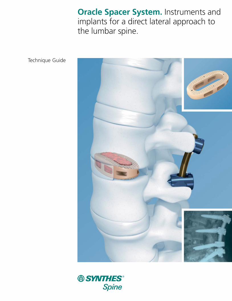
Oracle Spacer System. Instruments andimplants for a direct lateral approach tothe lumbar spine.
Technique Guide
Introduction
Surgical Technique
Product Information
Table of Contents
Oracle Spacer System 2
AO Principles 4
Indications 5
Preparation 6
Preoperative Planning and Position Patient 7
Approach 8
Insert Retractor 11
Perform Discectomy 16
Prepare Endplates 17
Trial for Implant Size 18
Insert Implant 19
Supplemental Fixation 22
Implants 23
Instruments 25
Set Lists 32
Image intensifier control
Synthes
2 Synthes Oracle Spacer System Technique Guide
Oracle Spacer System
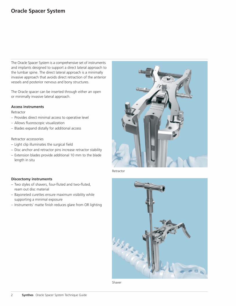
The Oracle Spacer System is a comprehensive set of instrumentsand implants designed to support a direct lateral approach tothe lumbar spine. The direct lateral approach is a minimallyinvasive approach that avoids direct retraction of the anteriorvessels and posterior nervous and bony structures.
The Oracle spacer can be inserted through either an open or minimally invasive lateral approach.
Access instrumentsRetractor
– Provides direct minimal access to operative level
– Allows fluoroscopic visualization
– Blades expand distally for additional access
Retractor accessories
– Light clip illuminates the surgical field
– Disc anchor and retractor pins increase retractor stability
– Extension blades provide additional 10 mm to the bladelength in situ
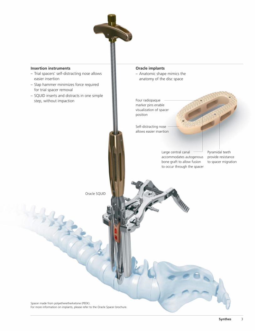
Discectomy instruments– Two styles of shavers, four-fluted and two-fluted,
ream out disc material
– Bayoneted curettes ensure maximum visibility while supporting a minimal exposure
– Instruments’ matte finish reduces glare from OR lighting
Retractor
Shaver
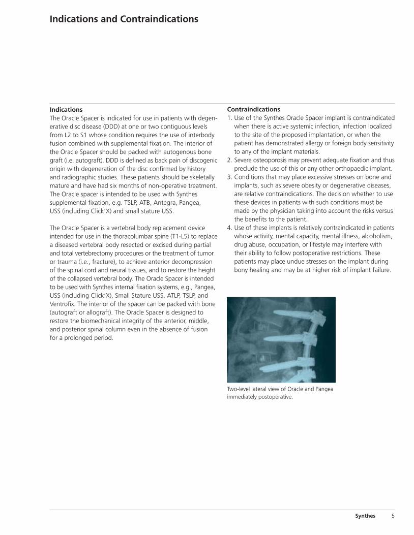
Four radiopaquemarker pins enable visualization of spacerposition
Synthes 3
Spacer made from polyetheretherketone (PEEK).For more information on implants, please refer to the Oracle Spacer brochure.
Oracle implants
Self-distracting nose allows easier insertion
Large central canal accommodates autogenousbone graft to allow fusionto occur through the spacer
Pyramidal teethprovide resistanceto spacer migration
– Anatomic shape mimics theanatomy of the disc space
Oracle SQUID
Insertion instruments– Trial spacers’ self-distracting nose allows
easier insertion
– Slap hammer minimizes force requiredfor trial spacer removal
– SQUID inserts and distracts in one simplestep, without impaction

4 Synthes Oracle Spacer System Technique Guide
AO Principles
In 1958, the AO formulated four basic principles, which havebecome the guidelines for internal fixation.1 They are:
– Anatomic reduction
– Stable internal fixation
– Preservation of blood supply
– Early, active mobilization
The fundamental aims of fracture treatment in the limbs andfusion of the spine are the same. A specific goal in the spineis returning as much function as possible to the injured neural elements.2
1. M.E. Müller, M. Allgöwer, R. Schneider, and H. Willenegger. Manual of Internal Fixation, 3rd Edition. Berlin: Springer-Verlag. 1991.
2. Ibid.
IndicationsThe Oracle Spacer is indicated for use in patients with degen-erative disc disease (DDD) at one or two contiguous levelsfrom L2 to S1 whose condition requires the use of interbodyfusion combined with supplemental fixation. The interior ofthe Oracle Spacer should be packed with autogenous bonegraft (i.e. autograft). DDD is defined as back pain of discogenicorigin with degeneration of the disc confirmed by historyand radiographic studies. These patients should be skeletallymature and have had six months of non-operative treatment.The Oracle spacer is intended to be used with Synthes supplemental fixation, e.g. TSLP, ATB, Antegra, Pangea, USS (including Click’X) and small stature USS.
The Oracle Spacer is a vertebral body replacement device intended for use in the thoracolumbar spine (T1-L5) to replacea diseased vertebral body resected or excised during partialand total vertebrectomy procedures or the treatment of tumoror trauma (i.e., fracture), to achieve anterior decompressionof the spinal cord and neural tissues, and to restore the heightof the collapsed vertebral body. The Oracle Spacer is intendedto be used with Synthes internal fixation systems, e.g., Pangea,USS (including Click’X), Small Stature USS, ATLP, TSLP, andVentrofix. The interior of the spacer can be packed with bone(autograft or allograft). The Oracle Spacer is designed to restore the biomechanical integrity of the anterior, middle,and posterior spinal column even in the absence of fusion for a prolonged period.
Contraindications1. Use of the Synthes Oracle Spacer implant is contraindicated
when there is active systemic infection, infection localizedto the site of the proposed implantation, or when the patient has demonstrated allergy or foreign body sensitivityto any of the implant materials.
2. Severe osteoporosis may prevent adequate fixation and thuspreclude the use of this or any other orthopaedic implant.
3. Conditions that may place excessive stresses on bone andimplants, such as severe obesity or degenerative diseases,are relative contraindications. The decision whether to usethese devices in patients with such conditions must bemade by the physician taking into account the risks versusthe benefits to the patient.
4. Use of these implants is relatively contraindicated in patientswhose activity, mental capacity, mental illness, alcoholism,drug abuse, occupation, or lifestyle may interfere withtheir ability to follow postoperative restrictions. These patients may place undue stresses on the implant duringbony healing and may be at higher risk of implant failure.
Synthes 5
Indications and Contraindications
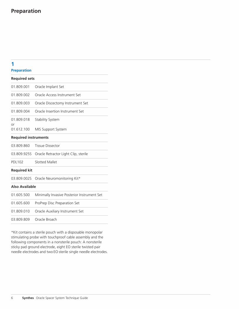
Two-level lateral view of Oracle and Pangeaimmediately postoperative.
Preparation
1Preparation
Required sets
01.809.001 Oracle Implant Set
01.809.002 Oracle Access Instrument Set
01.809.003 Oracle Discectomy Instrument Set
01.809.004 Oracle Insertion Instrument Set
01.809.018 Stability Systemor01.612.100 MIS Support System
Required instruments
03.809.860 Tissue Dissector
03.809.925S Oracle Retractor Light Clip, sterile
PDL102 Slotted Mallet
Required kit
03.809.002S Oracle Neuromonitoring Kit*
Also Available
01.605.500 Minimally Invasive Posterior Instrument Set
01.605.600 ProPrep Disc Preparation Set
01.809.010 Oracle Auxiliary Instrument Set
03.809.809 Oracle Broach
*Kit contains a sterile pouch with a disposable monopolarstimulating probe with touchproof cable assembly and thefollowing components in a nonsterile pouch: A nonsterilesticky pad ground electrode, eight EO sterile twisted pairneedle electrodes and two EO sterile single needle electrodes.
6 Synthes Oracle Spacer System Technique Guide
Preoperative Planning and Position Patient
Synthes 7
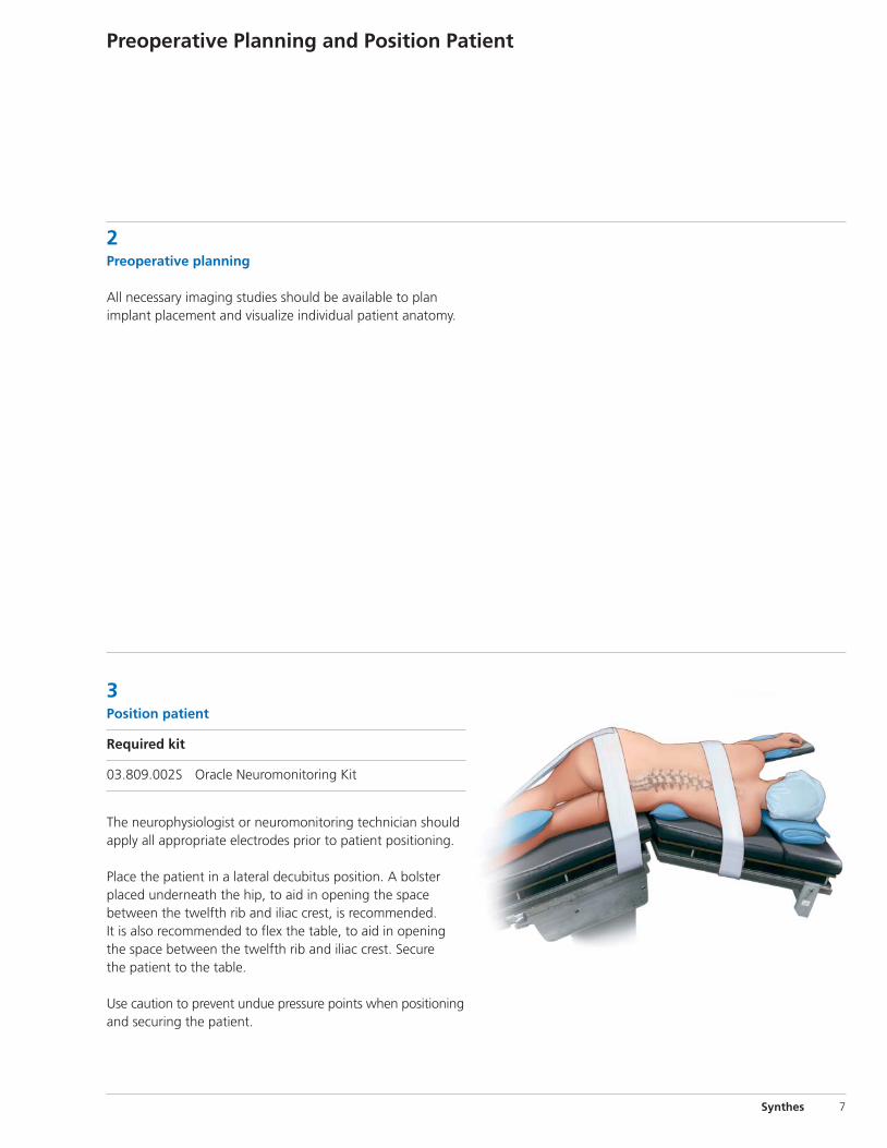
3 Position patient
Required kit
03.809.002S Oracle Neuromonitoring Kit
The neurophysiologist or neuromonitoring technician shouldapply all appropriate electrodes prior to patient positioning.
Place the patient in a lateral decubitus position. A bolsterplaced underneath the hip, to aid in opening the space between the twelfth rib and iliac crest, is recommended. It is also recommended to flex the table, to aid in openingthe space between the twelfth rib and iliac crest. Secure the patient to the table.
Use caution to prevent undue pressure points when positioningand securing the patient.
2Preoperative planning
All necessary imaging studies should be available to planimplant placement and visualize individual patient anatomy.
8 Synthes Oracle Spacer System Technique Guide
Approach
4Approach spine
Instruments
03.809.002S Oracle Neuromonitoring Kit
03.809.858* Small Adjacent Dilator
03.809.859* Large Adjacent Dilator
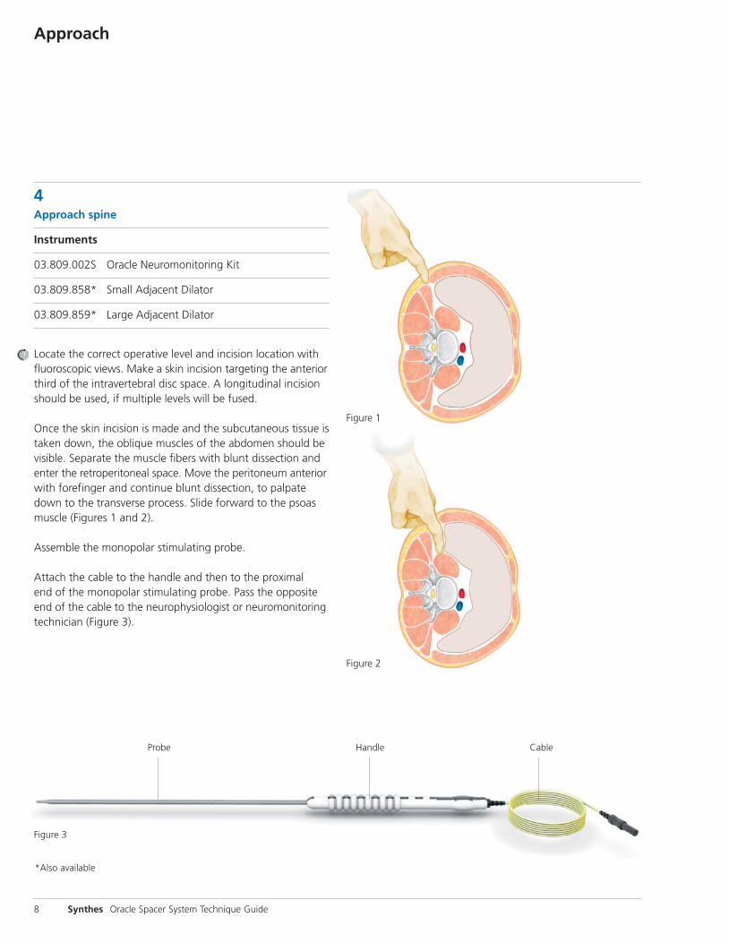
Locate the correct operative level and incision location with fluoroscopic views. Make a skin incision targeting the anteriorthird of the intravertebral disc space. A longitudinal incisionshould be used, if multiple levels will be fused.
Once the skin incision is made and the subcutaneous tissue istaken down, the oblique muscles of the abdomen should bevisible. Separate the muscle fibers with blunt dissection andenter the retroperitoneal space. Move the peritoneum anteriorwith forefinger and continue blunt dissection, to palpatedown to the transverse process. Slide forward to the psoasmuscle (Figures 1 and 2).
Assemble the monopolar stimulating probe.
Attach the cable to the handle and then to the proximal end of the monopolar stimulating probe. Pass the oppositeend of the cable to the neurophysiologist or neuromonitoringtechnician (Figure 3).
CableHandle
Figure 1
Figure 2
Probe
Figure 3
*Also available
Synthes 9
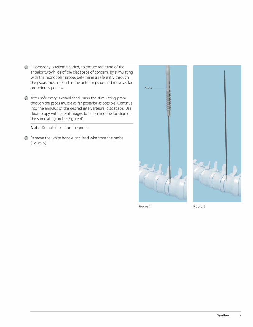
Fluoroscopy is recommended, to ensure targeting of the anterior two-thirds of the disc space of concern. By stimulatingwith the monopolar probe, determine a safe entry throughthe psoas muscle. Start in the anterior psoas and move as farposterior as possible.
After safe entry is established, push the stimulating probethrough the psoas muscle as far posterior as possible. Continueinto the annulus of the desired intervertebral disc space. Usefluoroscopy with lateral images to determine the location ofthe stimulating probe (Figure 4).
Note: Do not impact on the probe.
Remove the white handle and lead wire from the probe (Figure 5).
Probe
Figure 4 Figure 5
Approach continued
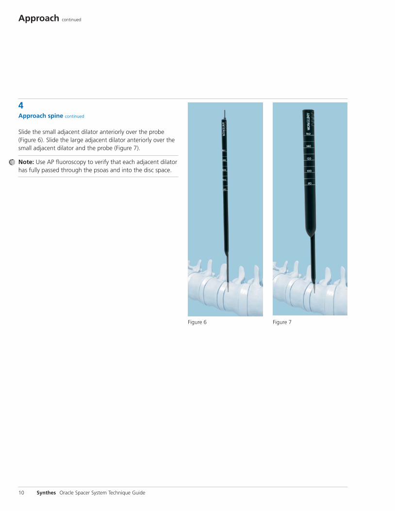
4Approach spine continued
Slide the small adjacent dilator anteriorly over the probe(Figure 6). Slide the large adjacent dilator anteriorly over thesmall adjacent dilator and the probe (Figure 7).
Note: Use AP fluoroscopy to verify that each adjacent dilatorhas fully passed through the psoas and into the disc space.
10 Synthes Oracle Spacer System Technique Guide
Figure 6 Figure 7
Insert Retractor
Synthes 11
5Insert retractor
Instruments
03.809.857 Retractor Blade Driver
03.809.900 Retractor Handle
03.809.903– Retractor Blades, 03.809.915 40 mm–160 mm
03.809.918 Retractor Blade Extension
03.809.919 Retractor Intradiscal Anchor
03.809.923 Retractor Extension Driver
03.809.941 Universal Arm
03.809.942 Table Clamp, for Universal Arm
388.14 Socket Wrench with straight handle
Optional instruments
03.612.031 Fiber Optic Light Cable
03.809.925S* Oracle Retractor Light Clip, sterile
03.809.943 Retractor Pin
03.820.101 Self-Retaining Screwdriver
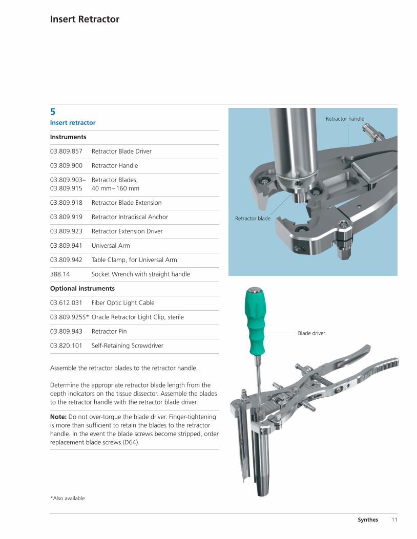
Assemble the retractor blades to the retractor handle.
Determine the appropriate retractor blade length from thedepth indicators on the tissue dissector. Assemble the bladesto the retractor handle with the retractor blade driver.
Note: Do not over-torque the blade driver. Finger-tighteningis more than sufficient to retain the blades to the retractorhandle. In the event the blade screws become stripped, orderreplacement blade screws (D64).
Retractor handle
Retractor blade
Blade driver
*Also available
5Insert retractor continued
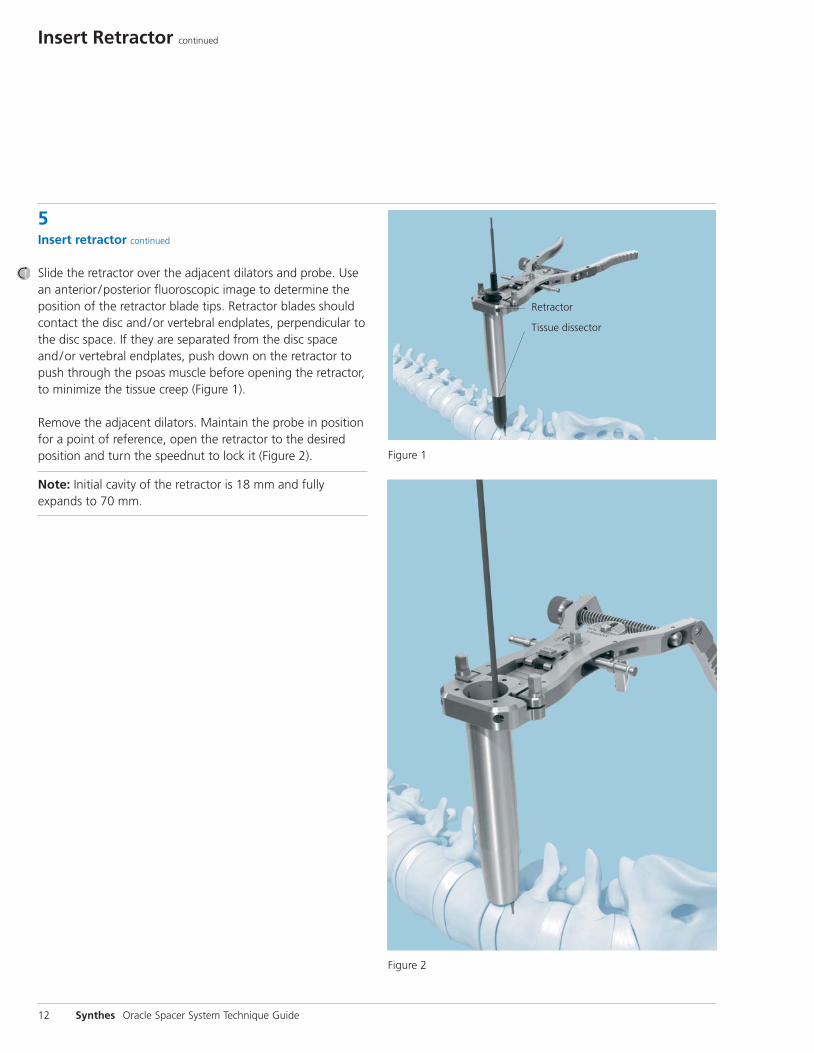
Slide the retractor over the adjacent dilators and probe. Usean anterior /posterior fluoroscopic image to determine theposition of the retractor blade tips. Retractor blades shouldcontact the disc and/or vertebral endplates, perpendicular tothe disc space. If they are separated from the disc spaceand/or vertebral endplates, push down on the retractor topush through the psoas muscle before opening the retractor,to minimize the tissue creep (Figure 1) .
Remove the adjacent dilators. Maintain the probe in positionfor a point of reference, open the retractor to the desired position and turn the speednut to lock it (Figure 2).
Note: Initial cavity of the retractor is 18 mm and fully expands to 70 mm.
12 Synthes Oracle Spacer System Technique Guide
Insert Retractor continued
Retractor
Tissue dissector
Figure 1
Figure 2
Synthes 13
Figure 4
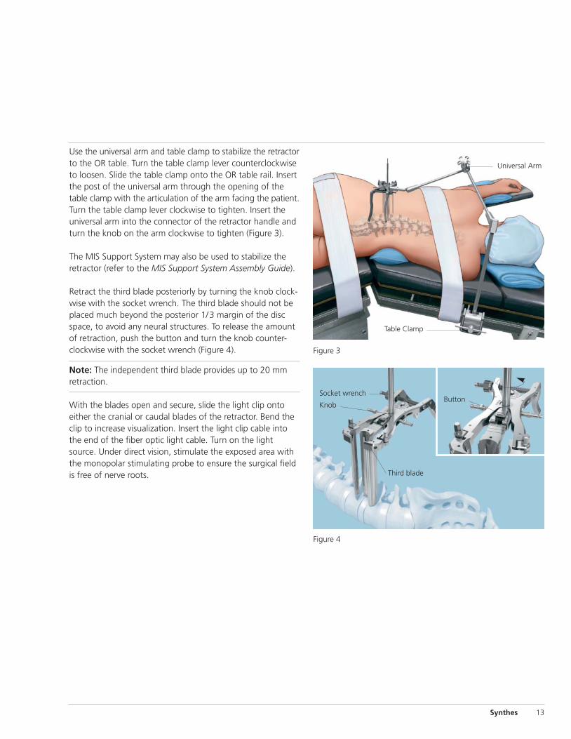
Socket wrench
Knob
Third blade
Button
Figure 3
Table Clamp
Universal Arm
Use the universal arm and table clamp to stabilize the retractorto the OR table. Turn the table clamp lever counterclockwiseto loosen. Slide the table clamp onto the OR table rail. Insertthe post of the universal arm through the opening of thetable clamp with the articulation of the arm facing the patient.Turn the table clamp lever clockwise to tighten. Insert theuniversal arm into the connector of the retractor handle andturn the knob on the arm clockwise to tighten (Figure 3).
The MIS Support System may also be used to stabilize the retractor (refer to the MIS Support System Assembly Guide).
Retract the third blade posteriorly by turning the knob clock-wise with the socket wrench. The third blade should not beplaced much beyond the posterior 1/3 margin of the discspace, to avoid any neural structures. To release the amountof retraction, push the button and turn the knob counter-clockwise with the socket wrench (Figure 4).
Note: The independent third blade provides up to 20 mm retraction.
With the blades open and secure, slide the light clip onto either the cranial or caudal blades of the retractor. Bend theclip to increase visualization. Insert the light clip cable intothe end of the fiber optic light cable. Turn on the lightsource. Under direct vision, stimulate the exposed area withthe monopolar stimulating probe to ensure the surgical fieldis free of nerve roots.
Insert Retractor continued
5Insert retractor continued
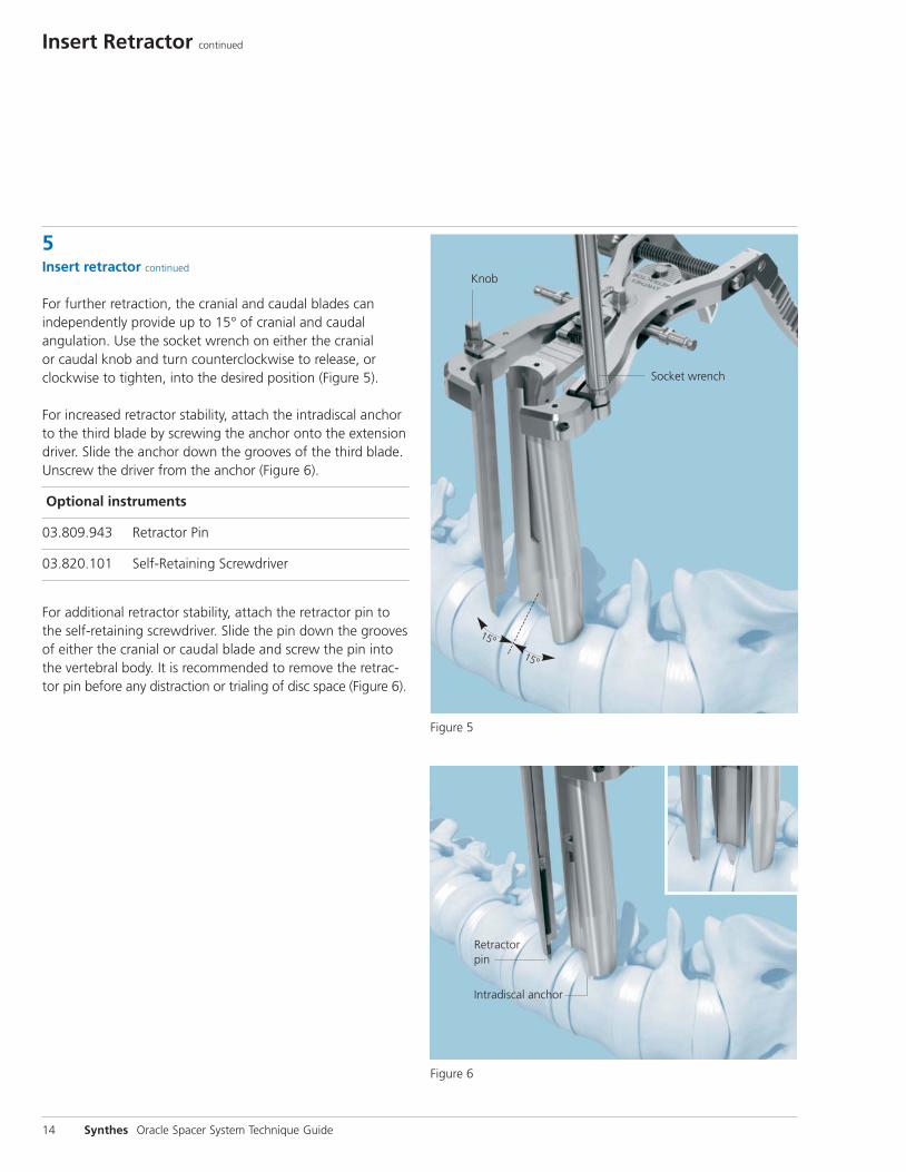
For further retraction, the cranial and caudal blades can independently provide up to 15° of cranial and caudalangulation. Use the socket wrench on either the cranial or caudal knob and turn counterclockwise to release, orclockwise to tighten, into the desired position (Figure 5).
For increased retractor stability, attach the intradiscal anchorto the third blade by screwing the anchor onto the extensiondriver. Slide the anchor down the grooves of the third blade.Unscrew the driver from the anchor (Figure 6).
Optional instruments
03.809.943 Retractor Pin
03.820.101 Self-Retaining Screwdriver
For additional retractor stability, attach the retractor pin tothe self-retaining screwdriver. Slide the pin down the groovesof either the cranial or caudal blade and screw the pin intothe vertebral body. It is recommended to remove the retrac-tor pin before any distraction or trialing of disc space (Figure 6).
14 Synthes Oracle Spacer System Technique Guide
Intradiscal anchor
Knob
Socket wrench
Figure 5
Figure 6
Retractor pin
15º
15º
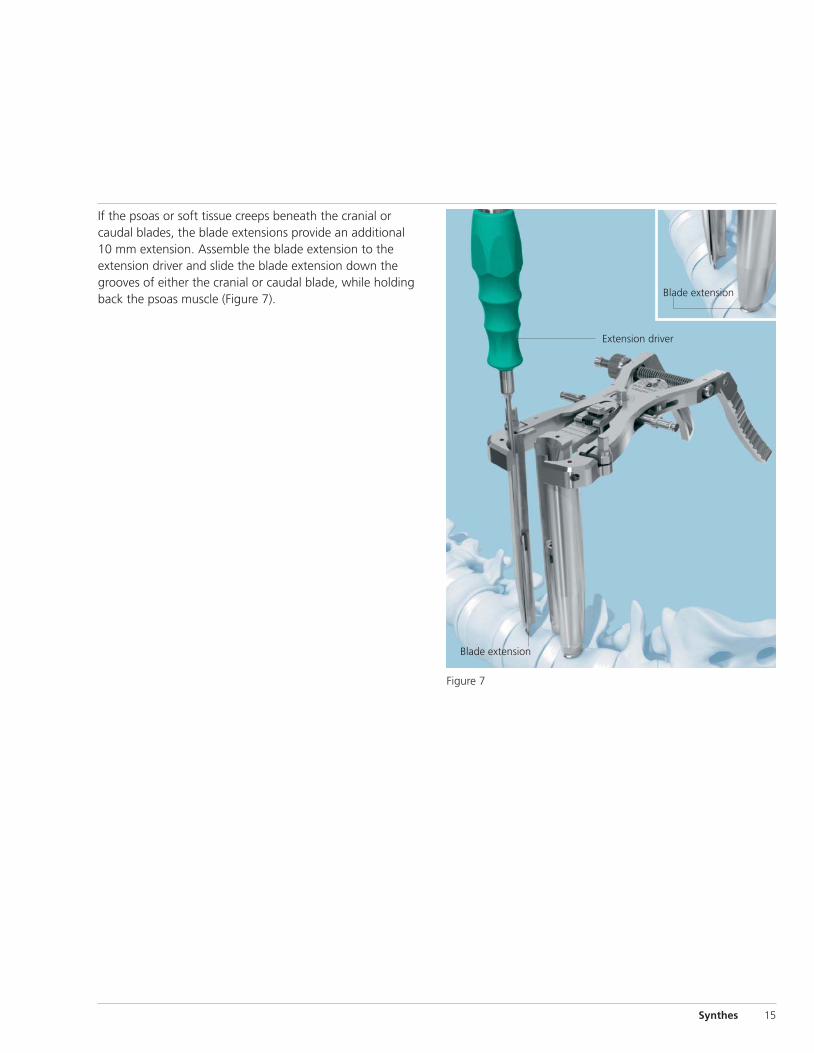
If the psoas or soft tissue creeps beneath the cranial or caudal blades, the blade extensions provide an additional10 mm extension. Assemble the blade extension to the extension driver and slide the blade extension down thegrooves of either the cranial or caudal blade, while holdingback the psoas muscle (Figure 7).
Synthes 15
Extension driver
Figure 7
Blade extension
Blade extension
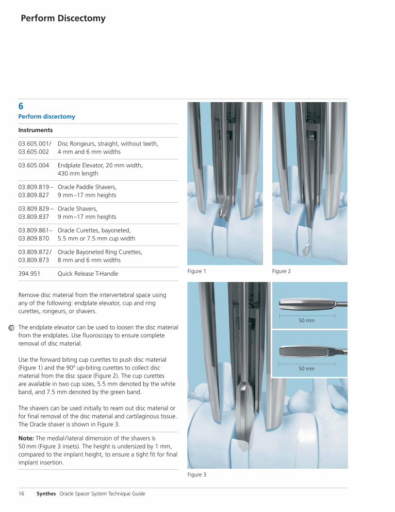
6Perform discectomy
Instruments
03.605.001/ Disc Rongeurs, straight, without teeth, 03.605.002 4 mm and 6 mm widths
03.605.004 Endplate Elevator, 20 mm width, 430 mm length
03.809.819 – Oracle Paddle Shavers,03.809.827 9 mm–17 mm heights
03.809.829 – Oracle Shavers, 03.809.837 9 mm–17 mm heights
03.809.861– Oracle Curettes, bayoneted,03.809.870 5.5 mm or 7.5 mm cup width
03.809.872/ Oracle Bayoneted Ring Curettes, 03.809.873 8 mm and 6 mm widths
394.951 Quick Release T-Handle
Remove disc material from the intervertebral space using any of the following: endplate elevator, cup and ringcurettes, rongeurs, or shavers.
The endplate elevator can be used to loosen the disc materialfrom the endplates. Use fluoroscopy to ensure complete removal of disc material.
Use the forward biting cup curettes to push disc material(Figure 1) and the 90º up-biting curettes to collect disc material from the disc space (Figure 2). The cup curettes are available in two cup sizes, 5.5 mm denoted by the whiteband, and 7.5 mm denoted by the green band.
The shavers can be used initially to ream out disc material orfor final removal of the disc material and cartilaginous tissue.The Oracle shaver is shown in Figure 3.
Note: The medial / lateral dimension of the shavers is 50 mm (Figure 3 insets). The height is undersized by 1 mm,compared to the implant height, to ensure a tight fit for finalimplant insertion.
16 Synthes Oracle Spacer System Technique Guide
Perform Discectomy
50 mm
Figure 1 Figure 2
Figure 3
50 mm
Prepare Endplates
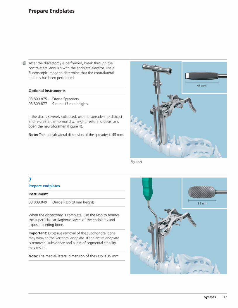
After the discectomy is performed, break through the contralateral annulus with the endplate elevator. Use a fluoroscopic image to determine that the contralateral annulus has been perforated.
Optional instruments
03.809.875– Oracle Spreaders, 03.809.877 9 mm–13 mm heights
If the disc is severely collapsed, use the spreaders to distractand re-create the normal disc height, restore lordosis, andopen the neuroforamen (Figure 4).
Note: The medial / lateral dimension of the spreader is 45 mm.
Synthes 17
7Prepare endplates
Instrument
03.809.849 Oracle Rasp (8 mm height)
When the discectomy is complete, use the rasp to removethe superficial cartilaginous layers of the endplates and expose bleeding bone.
Important: Excessive removal of the subchondral bone may weaken the vertebral endplate. If the entire endplate is removed, subsidence and a loss of segmental stability may result.
Note: The medial / lateral dimension of the rasp is 35 mm.
45 mm
Figure 4
35 mm
Trial for Implant Size
18 Synthes Oracle Spacer System Technique Guide
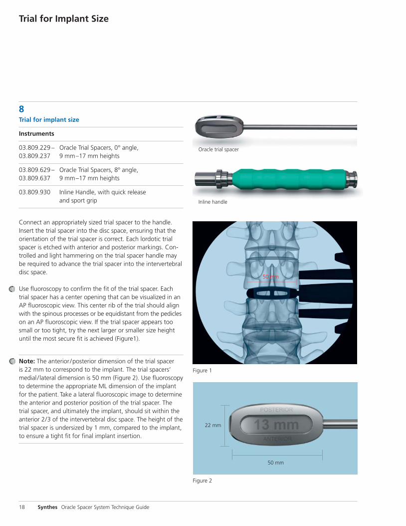
8Trial for implant size
Instruments
03.809.229 – Oracle Trial Spacers, 0° angle,03.809.237 9 mm–17 mm heights
03.809.629 – Oracle Trial Spacers, 8º angle,03.809.637 9 mm–17 mm heights
03.809.930 Inline Handle, with quick release and sport grip
Connect an appropriately sized trial spacer to the handle. Insert the trial spacer into the disc space, ensuring that theorientation of the trial spacer is correct. Each lordotic trialspacer is etched with anterior and posterior markings. Con-trolled and light hammering on the trial spacer handle maybe required to advance the trial spacer into the intervertebraldisc space.
Use fluoroscopy to confirm the fit of the trial spacer. Eachtrial spacer has a center opening that can be visualized in anAP fluoroscopic view. This center rib of the trial should alignwith the spinous processes or be equidistant from the pedicleson an AP fluoroscopic view. If the trial spacer appears toosmall or too tight, try the next larger or smaller size heightuntil the most secure fit is achieved (Figure1).
Note: The anterior /posterior dimension of the trial spacer is 22 mm to correspond to the implant. The trial spacers’ medial / lateral dimension is 50 mm (Figure 2). Use fluoroscopyto determine the appropriate ML dimension of the implantfor the patient. Take a lateral fluoroscopic image to determinethe anterior and posterior position of the trial spacer. Thetrial spacer, and ultimately the implant, should sit within theanterior 2/3 of the intervertebral disc space. The height of thetrial spacer is undersized by 1 mm, compared to the implant,to ensure a tight fit for final implant insertion.
Oracle trial spacer
Inline handle
50 mm
22 mm
50 mm
Figure 1
Figure 2
Insert Implant
Synthes 19
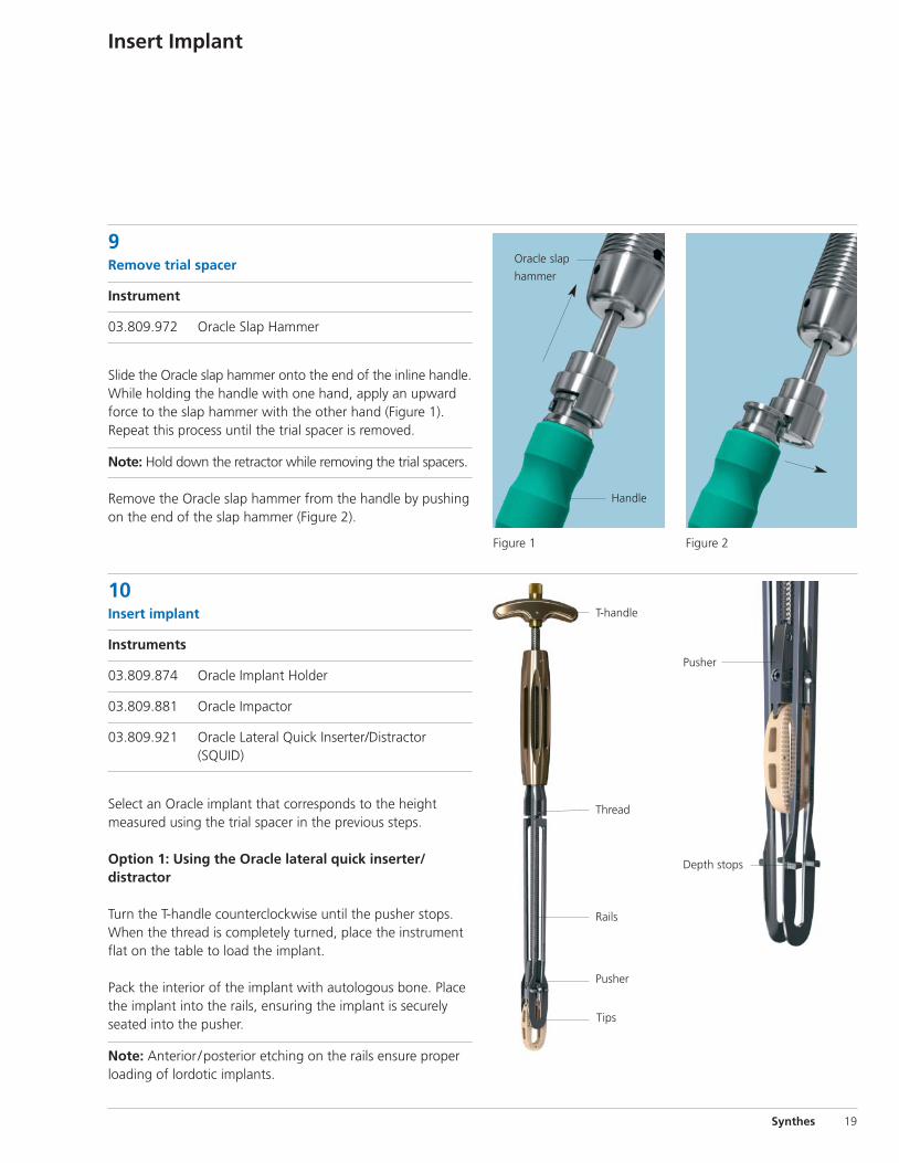
9Remove trial spacer
Instrument
03.809.972 Oracle Slap Hammer
Slide the Oracle slap hammer onto the end of the inline handle.While holding the handle with one hand, apply an upwardforce to the slap hammer with the other hand (Figure 1). Repeat this process until the trial spacer is removed.
Note: Hold down the retractor while removing the trial spacers.
Remove the Oracle slap hammer from the handle by pushingon the end of the slap hammer (Figure 2).
10Insert implant
Instruments
03.809.874 Oracle Implant Holder
03.809.881 Oracle Impactor
03.809.921 Oracle Lateral Quick Inserter/Distractor (SQUID)
Select an Oracle implant that corresponds to the heightmeasured using the trial spacer in the previous steps.
Option 1: Using the Oracle lateral quick inserter/ distractor
Turn the T-handle counterclockwise until the pusher stops.When the thread is completely turned, place the instrumentflat on the table to load the implant.
Pack the interior of the implant with autologous bone. Placethe implant into the rails, ensuring the implant is securelyseated into the pusher.
Note: Anterior /posterior etching on the rails ensure properloading of lordotic implants.
Oracle slap
hammer
Pusher
Thread
Rails
T-handle
Figure 1 Figure 2
Depth stops
Pusher
Tips
Handle
20 Synthes Oracle Spacer System Technique Guide
Insert Implant continued
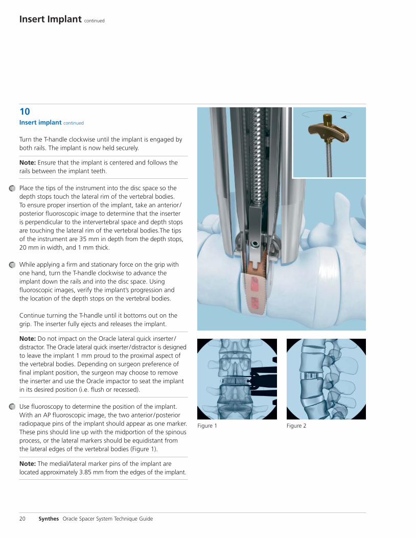
10Insert implant continued
Turn the T-handle clockwise until the implant is engaged byboth rails. The implant is now held securely.
Note: Ensure that the implant is centered and follows therails between the implant teeth.
Place the tips of the instrument into the disc space so thedepth stops touch the lateral rim of the vertebral bodies. To ensure proper insertion of the implant, take an anterior /posterior fluoroscopic image to determine that the inserter is perpendicular to the intervertebral space and depth stops are touching the lateral rim of the vertebral bodies.The tipsof the instrument are 35 mm in depth from the depth stops,20 mm in width, and 1 mm thick.
While applying a firm and stationary force on the grip withone hand, turn the T-handle clockwise to advance the implant down the rails and into the disc space. Using fluoroscopic images, verify the implant’s progression andthe location of the depth stops on the vertebral bodies.
Continue turning the T-handle until it bottoms out on thegrip. The inserter fully ejects and releases the implant.
Note: Do not impact on the Oracle lateral quick inserter /distractor. The Oracle lateral quick inserter/distractor is designedto leave the implant 1 mm proud to the proximal aspect ofthe vertebral bodies. Depending on surgeon preference of final implant position, the surgeon may choose to removethe inserter and use the Oracle impactor to seat the implantin its desired position (i.e. flush or recessed).
Use fluoroscopy to determine the position of the implant.With an AP fluoroscopic image, the two anterior /posteriorradiopaque pins of the implant should appear as one marker.These pins should line up with the midportion of the spinousprocess, or the lateral markers should be equidistant fromthe lateral edges of the vertebral bodies (Figure 1).
Note: The medial/lateral marker pins of the implant are located approximately 3.85 mm from the edges of the implant.
Figure 1 Figure 2
Synthes 21
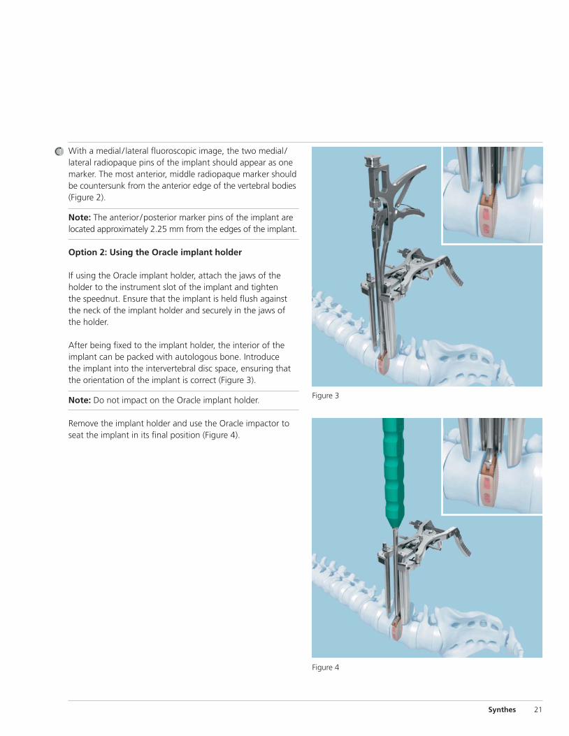
With a medial / lateral fluoroscopic image, the two medial /lateral radiopaque pins of the implant should appear as onemarker. The most anterior, middle radiopaque marker shouldbe countersunk from the anterior edge of the vertebral bodies(Figure 2).
Note: The anterior /posterior marker pins of the implant arelocated approximately 2.25 mm from the edges of the implant.
Option 2: Using the Oracle implant holder
If using the Oracle implant holder, attach the jaws of theholder to the instrument slot of the implant and tighten the speednut. Ensure that the implant is held flush againstthe neck of the implant holder and securely in the jaws ofthe holder.
After being fixed to the implant holder, the interior of theimplant can be packed with autologous bone. Introduce the implant into the intervertebral disc space, ensuring thatthe orientation of the implant is correct (Figure 3).
Note: Do not impact on the Oracle implant holder.
Remove the implant holder and use the Oracle impactor toseat the implant in its final position (Figure 4).
Figure 3
Figure 4
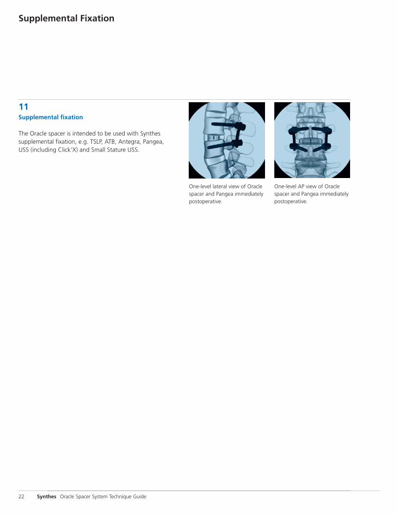
11Supplemental fixation
The Oracle spacer is intended to be used with Synthes supplemental fixation, e.g. TSLP, ATB, Antegra, Pangea, USS (including Click’X) and Small Stature USS.
22 Synthes Oracle Spacer System Technique Guide
Supplemental Fixation
One-level lateral view of Oraclespacer and Pangea immediatelypostoperative.
One-level AP view of Oraclespacer and Pangea immediatelypostoperative.
Synthes 23
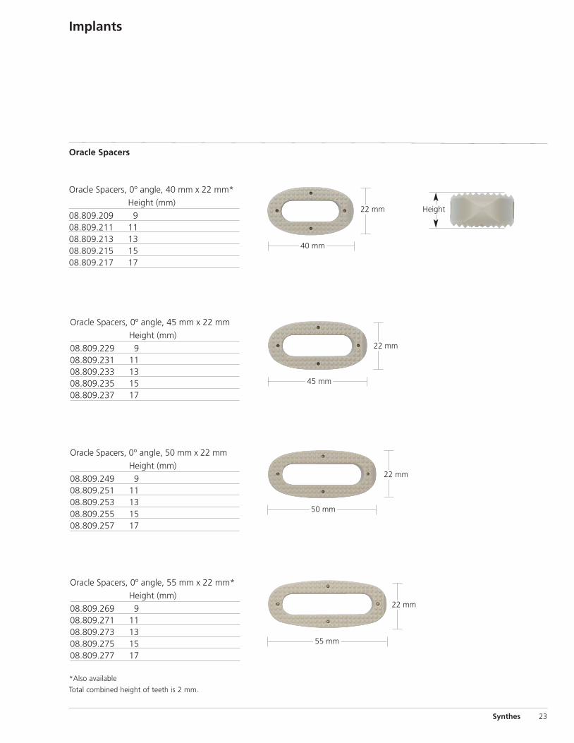
Implants
Oracle Spacers, 0º angle, 40 mm x 22 mm*
Height (mm)
08.809.209 9 08.809.211 1108.809.213 1308.809.215 1508.809.217 17
Oracle Spacers, 0º angle, 45 mm x 22 mm
Height (mm)
08.809.229 9 08.809.231 1108.809.233 1308.809.235 1508.809.237 17
Oracle Spacers, 0º angle, 50 mm x 22 mm
Height (mm)
08.809.249 9 08.809.251 1108.809.253 1308.809.255 1508.809.257 17
40 mm
22 mm
50 mm
22 mm
45 mm
Oracle Spacers, 0º angle, 55 mm x 22 mm*
Height (mm)
08.809.269 9 08.809.271 1108.809.273 1308.809.275 1508.809.277 17
55 mm
22 mm
Oracle Spacers
22 mm
*Also available
Total combined height of teeth is 2 mm.
Height
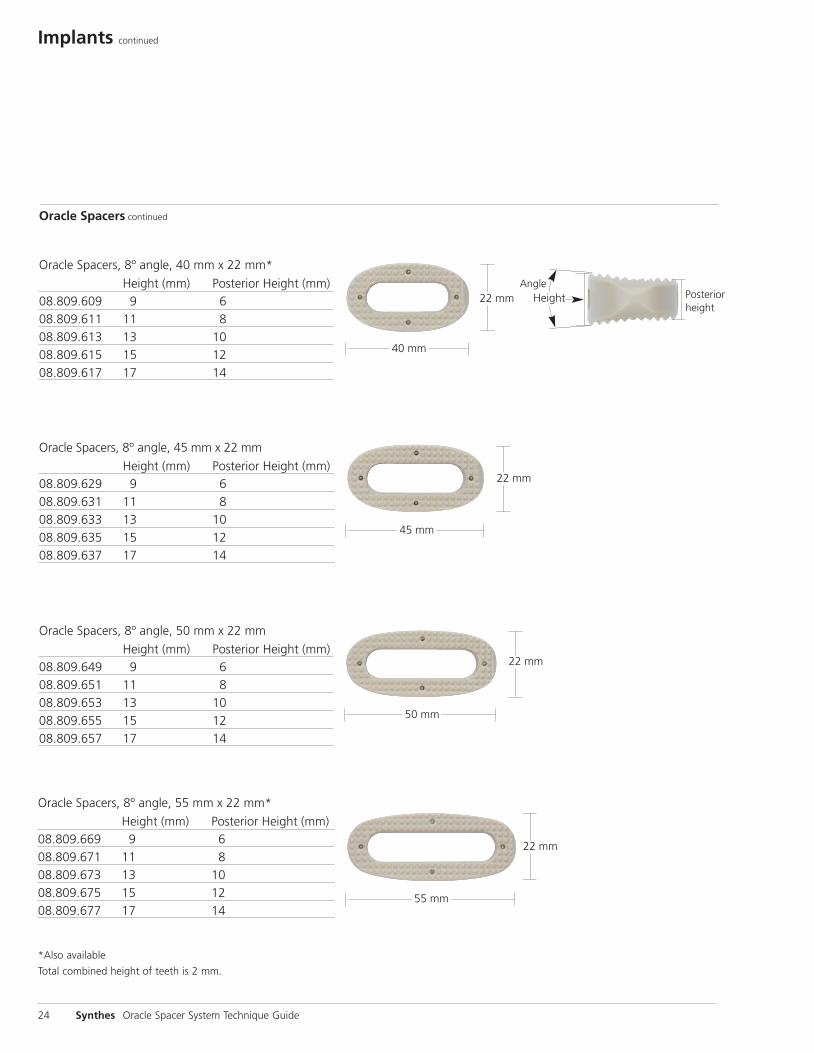
*Also available
Total combined height of teeth is 2 mm.
heightPosterior
Implants continued
24 Synthes Oracle Spacer System Technique Guide
Oracle Spacers, 8º angle, 55 mm x 22 mm*
Height (mm) Posterior Height (mm)08.809.669 9 6 08.809.671 11 808.809.673 13 1008.809.675 15 1208.809.677 17 14
Oracle Spacers, 8º angle, 40 mm x 22 mm*
Height (mm) Posterior Height (mm)08.809.609 9 608.809.611 11 808.809.613 13 1008.809.615 15 1208.809.617 17 14
Oracle Spacers, 8º angle, 45 mm x 22 mm
Height (mm) Posterior Height (mm)08.809.629 9 608.809.631 11 808.809.633 13 1008.809.635 15 1208.809.637 17 14
45 mm
22 mm
40 mm
Oracle Spacers, 8º angle, 50 mm x 22 mm
Height (mm) Posterior Height (mm)08.809.649 9 608.809.651 11 808.809.653 13 1008.809.655 15 1208.809.657 17 14
50 mm
22 mm
55 mm
Oracle Spacers continued
22 mm
22 mm
AngleHeight
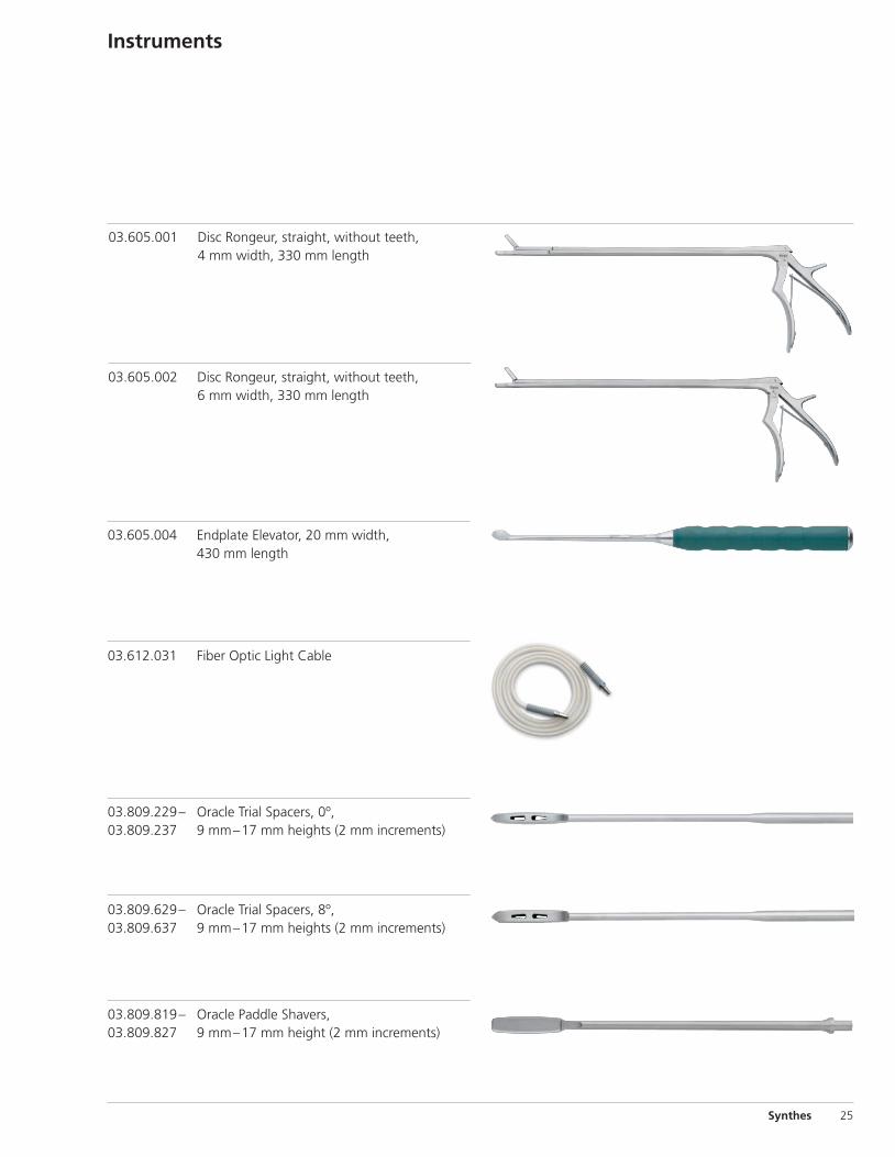
Instruments
Synthes 25
03.605.001 Disc Rongeur, straight, without teeth, 4 mm width, 330 mm length
03.605.002 Disc Rongeur, straight, without teeth, 6 mm width, 330 mm length
03.605.004 Endplate Elevator, 20 mm width, 430 mm length
03.809.229– Oracle Trial Spacers, 0º,03.809.237 9 mm–17 mm heights (2 mm increments)
03.809.629– Oracle Trial Spacers, 8º, 03.809.637 9 mm–17 mm heights (2 mm increments)
03.809.819– Oracle Paddle Shavers, 03.809.827 9 mm–17 mm height (2 mm increments)
03.612.031 Fiber Optic Light Cable
03.809.857 Retractor Blade Driver
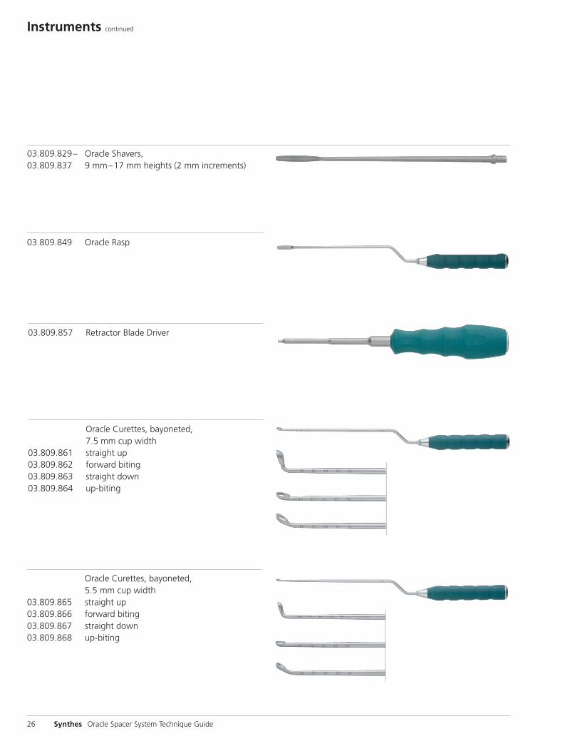
Oracle Curettes, bayoneted, 7.5 mm cup width 03.809.861 straight up03.809.862 forward biting03.809.863 straight down03.809.864 up-biting
Oracle Curettes, bayoneted, 5.5 mm cup width 03.809.865 straight up03.809.866 forward biting03.809.867 straight down03.809.868 up-biting
Instruments continued
26 Synthes Oracle Spacer System Technique Guide
03.809.849 Oracle Rasp
03.809.829– Oracle Shavers,03.809.837 9 mm–17 mm heights (2 mm increments)
Synthes 27
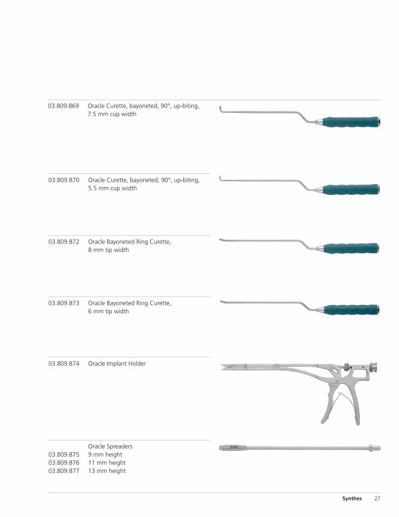
03.809.869 Oracle Curette, bayoneted, 90°, up-biting, 7.5 mm cup width
03.809.870 Oracle Curette, bayoneted, 90°, up-biting, 5.5 mm cup width
03.809.872 Oracle Bayoneted Ring Curette, 8 mm tip width
03.809.873 Oracle Bayoneted Ring Curette, 6 mm tip width
03.809.874 Oracle Implant Holder
Oracle Spreaders 03.809.875 9 mm height 03.809.876 11 mm height 03.809.877 13 mm height
Instruments continued
28 Synthes Oracle Spacer System Technique Guide
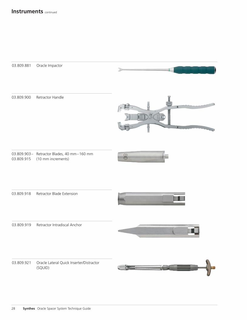
03.809.921 Oracle Lateral Quick Inserter/Distractor (SQUID)
03.809.881 Oracle Impactor
03.809.900 Retractor Handle
03.809.903– Retractor Blades, 40 mm–160 mm 03.809.915 (10 mm increments)
03.809.918 Retractor Blade Extension
03.809.919 Retractor Intradiscal Anchor
Synthes 29
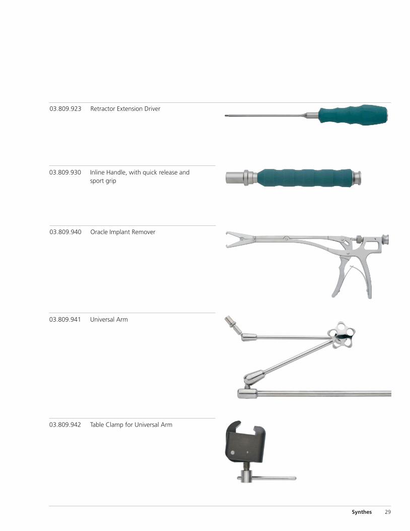
03.809.923 Retractor Extension Driver
03.809.930 Inline Handle, with quick release and sport grip
03.809.940 Oracle Implant Remover
03.809.942 Table Clamp for Universal Arm
03.809.941 Universal Arm
Instruments continued
30 Synthes Oracle Spacer System Technique Guide
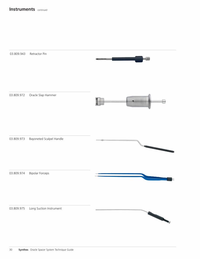
03.809.975 Long Suction Instrument
03.809.973 Bayoneted Scalpel Handle
03.809.974 Bipolar Forceps
03.809.972 Oracle Slap Hammer
03.809.943 Retractor Pin
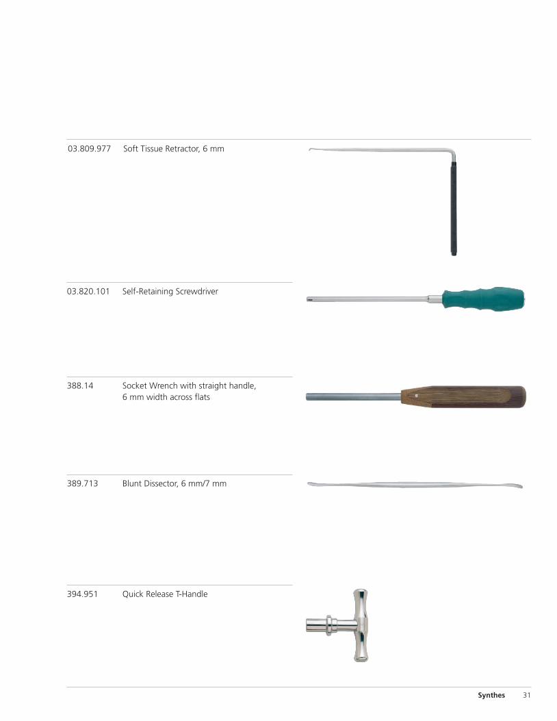
388.14 Socket Wrench with straight handle, 6 mm width across flats
389.713 Blunt Dissector, 6 mm/7 mm
394.951 Quick Release T-Handle
Synthes 31
03.820.101 Self-Retaining Screwdriver
03.809.977 Soft Tissue Retractor, 6 mm
32 Synthes Oracle Spacer System Technique Guide
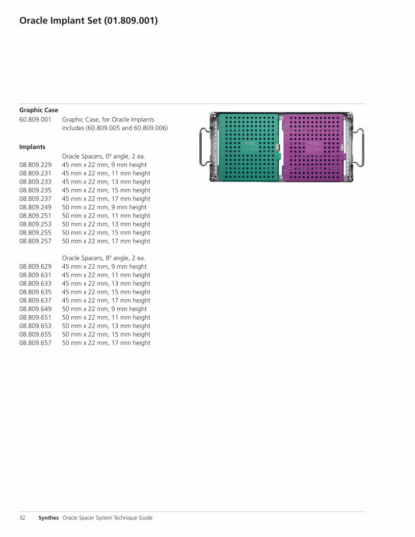
Graphic Case60.809.001 Graphic Case, for Oracle Implants includes (60.809.005 and 60.809.006)
Implants Oracle Spacers, 0º angle, 2 ea.08.809.229 45 mm x 22 mm, 9 mm height08.809.231 45 mm x 22 mm, 11 mm height08.809.233 45 mm x 22 mm, 13 mm height08.809.235 45 mm x 22 mm, 15 mm height08.809.237 45 mm x 22 mm, 17 mm height08.809.249 50 mm x 22 mm, 9 mm height08.809.251 50 mm x 22 mm, 11 mm height08.809.253 50 mm x 22 mm, 13 mm height08.809.255 50 mm x 22 mm, 15 mm height08.809.257 50 mm x 22 mm, 17 mm height
Oracle Spacers, 8º angle, 2 ea.08.809.629 45 mm x 22 mm, 9 mm height08.809.631 45 mm x 22 mm, 11 mm height08.809.633 45 mm x 22 mm, 13 mm height08.809.635 45 mm x 22 mm, 15 mm height08.809.637 45 mm x 22 mm, 17 mm height08.809.649 50 mm x 22 mm, 9 mm height08.809.651 50 mm x 22 mm, 11 mm height08.809.653 50 mm x 22 mm, 13 mm height08.809.655 50 mm x 22 mm, 15 mm height08.809.657 50 mm x 22 mm, 17 mm height
Oracle Implant Set (01.809.001)
Oracle Access Instrument Set (01.809.002)
Synthes 33
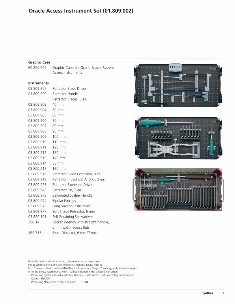
Graphic Case60.809.002 Graphic Case, for Oracle Spacer System Access Instruments
Instruments03.809.857 Retractor Blade Driver
03.809.900 Retractor Handle
Retractor Blades, 3 ea.
03.809.903 40 mm
03.809.904 50 mm
03.809.905 60 mm
03.809.906 70 mm
03.809.907 80 mm
03.809.908 90 mm
03.809.909 100 mm
03.809.910 110 mm
03.809.911 120 mm
03.809.912 130 mm
03.809.913 140 mm
03.809.914 50 mm
03.809.915 160 mm
03.809.918 Retractor Blade Extension, 3 ea.
03.809.919 Retractor Intradiscal Anchor, 2 ea.
03.809.923 Retractor Extension Driver
03.809.943 Retractor Pin, 3 ea.
03.809.973 Bayoneted Scalpel Handle
03.809.974 Bipolar Forceps
03.809.975 Long Suction Instrument
03.809.977 Soft Tissue Retractor, 6 mm
03.820.101 Self-Retaining Screwdriver
388.14 Socket Wrench with straight handle,
6 mm width across flats
389.713 Blunt Dissector, 6 mm/7 mm
Note: For additional information, please refer to package insert. For detailed cleaning and sterilization instructions, please refer tohttp://www.synthes.com/sites /NA/MedicalCommunity /Pages /Cleaning_and_Sterilization.aspxor to the below listed inserts, which will be included in the shipping container:– Processing Synthes Reusable Medical Devices—Instruments, Instrument Trays and Graphic
Cases—DJ1305– Processing Non-sterile Synthes Implants—DJ1304
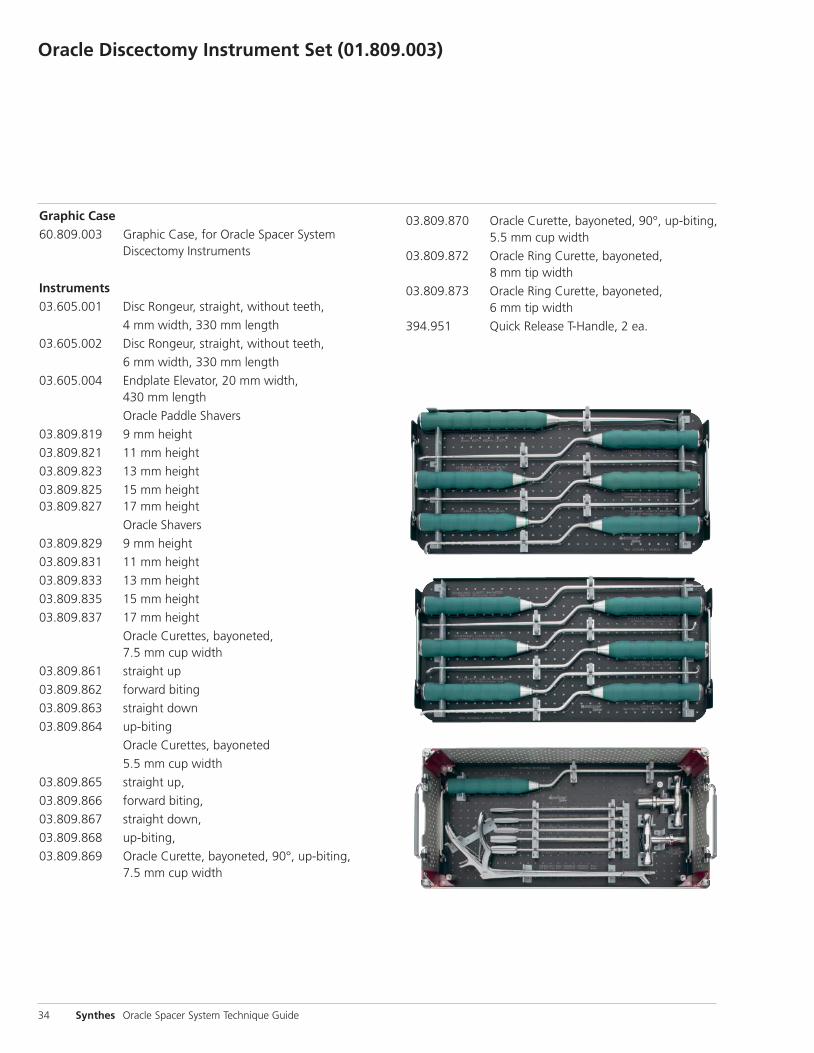
03.809.870 Oracle Curette, bayoneted, 90°, up-biting, 5.5 mm cup width
03.809.872 Oracle Ring Curette, bayoneted, 8 mm tip width
03.809.873 Oracle Ring Curette, bayoneted, 6 mm tip width
394.951 Quick Release T-Handle, 2 ea.
34 Synthes Oracle Spacer System Technique Guide
Oracle Discectomy Instrument Set (01.809.003)
Graphic Case60.809.003 Graphic Case, for Oracle Spacer System Discectomy Instruments
Instruments03.605.001 Disc Rongeur, straight, without teeth,
4 mm width, 330 mm length
03.605.002 Disc Rongeur, straight, without teeth,
6 mm width, 330 mm length
03.605.004 Endplate Elevator, 20 mm width, 430 mm length
Oracle Paddle Shavers
03.809.819 9 mm height
03.809.821 11 mm height
03.809.823 13 mm height
03.809.825 15 mm height03.809.827 17 mm height
Oracle Shavers
03.809.829 9 mm height
03.809.831 11 mm height
03.809.833 13 mm height
03.809.835 15 mm height
03.809.837 17 mm height
Oracle Curettes, bayoneted, 7.5 mm cup width
03.809.861 straight up
03.809.862 forward biting
03.809.863 straight down
03.809.864 up-biting
Oracle Curettes, bayoneted
5.5 mm cup width
03.809.865 straight up,
03.809.866 forward biting,
03.809.867 straight down,
03.809.868 up-biting,
03.809.869 Oracle Curette, bayoneted, 90°, up-biting, 7.5 mm cup width
Synthes 35
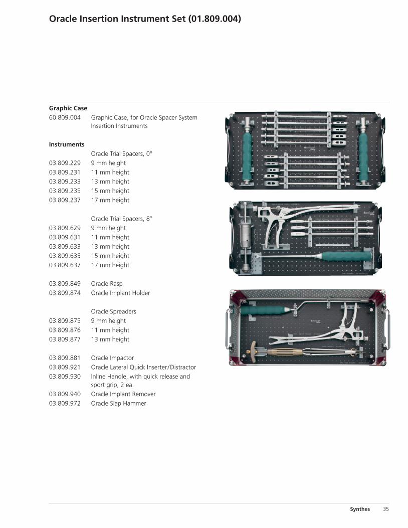
Oracle Insertion Instrument Set (01.809.004)
Graphic Case60.809.004 Graphic Case, for Oracle Spacer System Insertion Instruments
Instruments Oracle Trial Spacers, 0°
03.809.229 9 mm height
03.809.231 11 mm height
03.809.233 13 mm height
03.809.235 15 mm height
03.809.237 17 mm height
Oracle Trial Spacers, 8°
03.809.629 9 mm height
03.809.631 11 mm height
03.809.633 13 mm height
03.809.635 15 mm height
03.809.637 17 mm height
03.809.849 Oracle Rasp
03.809.874 Oracle Implant Holder
Oracle Spreaders
03.809.875 9 mm height
03.809.876 11 mm height
03.809.877 13 mm height
03.809.881 Oracle Impactor
03.809.921 Oracle Lateral Quick Inserter /Distractor
03.809.930 Inline Handle, with quick release and sport grip, 2 ea.
03.809.940 Oracle Implant Remover
03.809.972 Oracle Slap Hammer
36 Synthes Oracle Spacer System Technique Guide
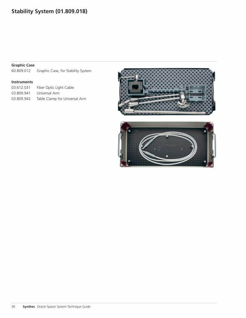
Stability System (01.809.018)
Graphic Case60.809.012 Graphic Case, for Stability System
Instruments03.612.031 Fiber Optic Light Cable
03.809.941 Universal Arm
03.809.942 Table Clamp for Universal Arm

Also Available
Sets01.612.100 MIS Support System01.605.500 Minimally Invasive Posterior Instrument Set01.605.600 ProPrep Disc Preparation Set01.809.010 Oracle Auxiliary Instrument Set
Kit03.809.002S Oracle Neuromonitoring Kit, sterile
Instruments03.809.809 Oracle Broach03.809.858 Small Adjacent Dilator03.809.859 Large Adjacent Dilator03.809.860 Tissue DissectorPDL102 Slotted Mallet
Accessories03.809.925S Oracle Retractor Light Clip, sterile
Implants Oracle Spacers, 0º angle
08.809.209 40 mm x 22 mm, 9 mm height08.809.211 40 mm x 22 mm, 11 mm height08.809.213 40 mm x 22 mm, 13 mm height08.809.215 40 mm x 22 mm, 15 mm height08.809.217 40 mm x 22 mm, 17 mm height08.809.269 55 mm x 22 mm, 9 mm height08.809.271 55 mm x 22 mm, 11 mm height08.809.273 55 mm x 22 mm, 13 mm height08.809.275 55 mm x 22 mm, 15 mm height08.809.277 55 mm x 22 mm, 17 mm height
Oracle Spacers, 8º angle08.809.609 40 mm x 22 mm, 9 mm height08.809.611 40 mm x 22 mm, 11 mm height08.809.613 40 mm x 22 mm, 13 mm height08.809.615 40 mm x 22 mm, 15 mm height08.809.617 40 mm x 22 mm, 17 mm height
08.809.669 55 mm x 22 mm, 9 mm height08.809.671 55 mm x 22 mm, 11 mm height08.809.673 55 mm x 22 mm, 13 mm height08.809.675 55 mm x 22 mm, 15 mm height08.809.677 55 mm x 22 mm, 17 mm height
Synthes

Synthes Spine1302 Wrights Lane EastWest Chester, PA 19380Telephone: (610) 719-5000To order: (800) 523-0322Fax: (610) 251-9056
Synthes (Canada) Ltd.2566 Meadowpine BoulevardMississauga, Ontario L5N 6P9Telephone: (905) 567-0440To order: (800) 668-1119Fax: (905) 567-3185
© 2009 Synthes, Inc. or its affiliates. All rights reserved. Click’X, Pangea and Synthes are trademarks of Synthes, Inc. or its affiliates. Printed in U.S.A. 3/12 J8158-D
www.synthes.com