Embed Size (px)
Citation preview

Oracle® SuperCluster M8 and SuperCluster M7 Configuration
Worksheets
Part No. E58632-07December 2017

Copyright © 2015, 2017, Oracle and/or its affiliates. All rights reserved.
This software and related documentation are provided under a license agreement containing restrictions on use and disclosure and are protected by intellectual property laws. Except as expressly permitted in your license agreement or allowed by law, you may not use, copy, reproduce, translate, broadcast, modify, license, transmit, distribute, exhibit, perform, publish, or display any part, in any form, or by any means. Reverse engineering, disassembly, or decompilation of this software, unless required by law for interoperability, is prohibited.
The information contained herein is subject to change without notice and is not warranted to be error-free. If you find any errors, please report them to us in writing.
If this is software or related documentation that is delivered to the U.S. Government or anyone licensing it on behalf of the U.S. Government, then the following notice is applicable:
U.S. GOVERNMENT END USERS. Oracle programs, including any operating system, integrated software, any programs installed on the hardware, and/or documentation, delivered to U.S. Government end users are "commercial computer software" pursuant to the applicable Federal Acquisition Regulation and agency-specific supplemental regulations. As such, use, duplication, disclosure, modification, and adaptation of the programs, including any operating system, integrated software, any programs installed on the hardware, and/or documentation, shall be subject to license terms and license restrictions applicable to the programs. No other rights are granted to the U.S. Government.
This software or hardware is developed for general use in a variety of information management applications. It is not developed or intended for use in any inherently dangerous applications, including applications that may create a risk of personal injury. If you use this software or hardware in dangerous applications, then you shall be responsible to take all appropriate fail-safe, backup, redundancy, and other measures to ensure its safe use. Oracle Corporation and its affiliates disclaim any liability for any damages caused by use of this software or hardware in dangerous applications.
Oracle and Java are registered trademarks of Oracle and/or its affiliates. Other names may be trademarks of their respective owners.
Intel and Intel Xeon are trademarks or registered trademarks of Intel Corporation. All SPARC trademarks are used under license and are trademarks or registered trademarks of SPARC International, Inc. AMD, Opteron, the AMD logo, and the AMD Opteron logo are trademarks or registered trademarks of Advanced Micro Devices. UNIX is a registered trademark of The Open Group.
This software or hardware and documentation may provide access to or information about content, products, and services from third parties. Oracle Corporation and its affiliates are not responsible for and expressly disclaim all warranties of any kind with respect to third-party content, products, and services unless otherwise set forth in an applicable agreement between you and Oracle. Oracle Corporation and its affiliates will not be responsible for any loss, costs, or damages incurred due to your access to or use of third-party content, products, or services, except as set forth in an applicable agreement between you and Oracle.
Documentation Accessibility
For information about Oracle's commitment to accessibility, visit the Oracle Accessibility Program website at http://www.oracle.com/pls/topic/lookup?ctx=acc&id=docacc.
Access to Oracle Support
Oracle customers that have purchased support have access to electronic support through My Oracle Support. For information, visit http://www.oracle.com/pls/topic/lookup?ctx=acc&id=info or visit http://www.oracle.com/pls/topic/lookup?ctx=acc&id=trs if you are hearing impaired.

Copyright © 2015, 2017, Oracle et/ou ses affiliés. Tous droits réservés.
Ce logiciel et la documentation qui l’accompagne sont protégés par les lois sur la propriété intellectuelle. Ils sont concédés sous licence et soumis à des restrictions d’utilisation et de divulgation. Sauf stipulation expresse de votre contrat de licence ou de la loi, vous ne pouvez pas copier, reproduire, traduire, diffuser, modifier, breveter, transmettre, distribuer, exposer, exécuter, publier ou afficher le logiciel, même partiellement, sous quelque forme et par quelque procédé que ce soit. Par ailleurs, il est interdit de procéder à toute ingénierie inverse du logiciel, de le désassembler ou de le décompiler, excepté à des fins d’interopérabilité avec des logiciels tiers ou tel que prescrit par la loi.
Les informations fournies dans ce document sont susceptibles de modification sans préavis. Par ailleurs, Oracle Corporation ne garantit pas qu’elles soient exemptes d’erreurs et vous invite, le cas échéant, à lui en faire part par écrit.
Si ce logiciel, ou la documentation qui l’accompagne, est concédé sous licence au Gouvernement des Etats-Unis, ou à toute entité qui délivre la licence de ce logiciel ou l’utilise pour le compte du Gouvernement des Etats-Unis, la notice suivante s’applique:
U.S. GOVERNMENT END USERS. Oracle programs, including any operating system, integrated software, any programs installed on the hardware, and/or documentation, delivered to U.S. Government end users are "commercial computer software" pursuant to the applicable Federal Acquisition Regulation and agency-specific supplemental regulations. As such, use, duplication, disclosure, modification, and adaptation of the programs, including any operating system, integrated software, any programs installed on the hardware, and/or documentation, shall be subject to license terms and license restrictions applicable to the programs. No other rights are granted to the U.S. Government.
Ce logiciel ou matériel a été développé pour un usage général dans le cadre d’applications de gestion des informations. Ce logiciel ou matériel n’est pas conçu ni n’est destiné à être utilisé dans des applications à risque, notamment dans des applications pouvant causer des dommages corporels. Si vous utilisez ce logiciel ou matériel dans le cadre d’applications dangereuses, il est de votre responsabilité de prendre toutes les mesures de secours, de sauvegarde, de redondance et autres mesures nécessaires à son utilisation dans des conditions optimales de sécurité. Oracle Corporation et ses affiliés déclinent toute responsabilité quant aux dommages causés par l’utilisation de ce logiciel ou matériel pour ce type d’applications.
Oracle et Java sont des marques déposées d’Oracle Corporation et/ou de ses affiliés. Tout autre nom mentionné peut correspondre à des marques appartenant à d’autres propriétaires qu’Oracle.
Intel et Intel Xeon sont des marques ou des marques déposées d’Intel Corporation. Toutes les marques SPARC sont utilisées sous licence et sont des marques ou des marques déposées de SPARC International, Inc. AMD, Opteron, le logo AMD et le logo AMD Opteron sont des marques ou des marques déposées d’Advanced Micro Devices. UNIX est une marque déposée d’The Open Group.
Ce logiciel ou matériel et la documentation qui l’accompagne peuvent fournir des informations ou des liens donnant accès à des contenus, des produits et des services émanant de tiers. Oracle Corporation et ses affiliés déclinent toute responsabilité ou garantie expresse quant aux contenus, produits ou services émanant de tiers, sauf mention contraire stipulée dans un contrat entre vous et Oracle. En aucun cas, Oracle Corporation et ses affiliés ne sauraient être tenus pour responsables des pertes subies, des coûts occasionnés ou des dommages causés par l’accès à des contenus, produits ou services tiers, ou à leur utilisation, sauf mention contraire stipulée dans un contrat entre vous et Oracle.
Accessibilité de la documentation
Pour plus d’informations sur l’engagement d’Oracle pour l’accessibilité à la documentation, visitez le site Web Oracle Accessibility Program, à l’adresse http://www.oracle.com/pls/topic/lookup?ctx=acc&id=docacc.
Accès au support électronique
Les clients Oracle qui ont souscrit un contrat de support ont accès au support électronique via My Oracle Support. Pour plus d’informations, visitez le site http://www.oracle.com/pls/topic/lookup?ctx=acc&id=info ou le site http://www.oracle.com/pls/topic/lookup?ctx=acc&id=trs si vous êtes malentendant.
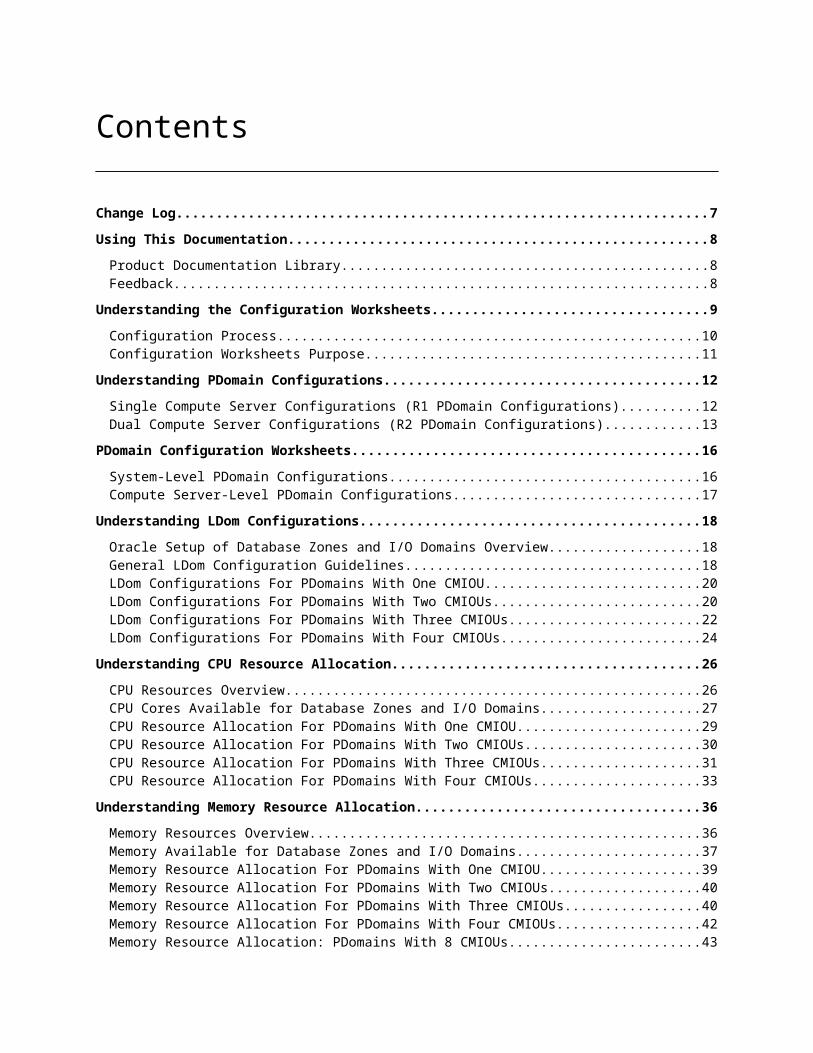
Contents
Change Log................................................................................................................7Using This Documentation........................................................................................8
Product Documentation Library..........................................................................................8Feedback.............................................................................................................................8
Understanding the Configuration Worksheets..........................................................9Configuration Process.......................................................................................................10Configuration Worksheets Purpose...................................................................................11
Understanding PDomain Configurations.................................................................12Single Compute Server Configurations (R1 PDomain Configurations)..............................12Dual Compute Server Configurations (R2 PDomain Configurations)................................13
PDomain Configuration Worksheets........................................................................16System-Level PDomain Configurations..............................................................................16Compute Server-Level PDomain Configurations...............................................................17
Understanding LDom Configurations......................................................................18Oracle Setup of Database Zones and I/O Domains Overview............................................18General LDom Configuration Guidelines...........................................................................18LDom Configurations For PDomains With One CMIOU....................................................20LDom Configurations For PDomains With Two CMIOUs..................................................20LDom Configurations For PDomains With Three CMIOUs................................................22LDom Configurations For PDomains With Four CMIOUs..................................................24
Understanding CPU Resource Allocation................................................................26CPU Resources Overview..................................................................................................26CPU Cores Available for Database Zones and I/O Domains..............................................27CPU Resource Allocation For PDomains With One CMIOU..............................................29CPU Resource Allocation For PDomains With Two CMIOUs.............................................30CPU Resource Allocation For PDomains With Three CMIOUs..........................................31CPU Resource Allocation For PDomains With Four CMIOUs............................................33
Understanding Memory Resource Allocation..........................................................36Memory Resources Overview............................................................................................36Memory Available for Database Zones and I/O Domains..................................................37Memory Resource Allocation For PDomains With One CMIOU........................................39Memory Resource Allocation For PDomains With Two CMIOUs......................................40Memory Resource Allocation For PDomains With Three CMIOUs....................................40Memory Resource Allocation For PDomains With Four CMIOUs......................................42Memory Resource Allocation: PDomains With 8 CMIOUs.................................................43
Understanding Client Access Network, Network Recipe, VLAN Tag, and RAC Cluster Options........................................................................................................44
Multiple Client Access Network Overview........................................................................44Network Recipe Overview.................................................................................................44VLAN Tag Overview..........................................................................................................45RAC Cluster Overview.......................................................................................................46

Determining Network IP Addresses.........................................................................47Network Overview.............................................................................................................48IP Addresses and Oracle Enterprise Manager Ops Center 12c Release 2........................49Management Network IP Addresses.................................................................................51Understanding Client Access Network IP Addresses........................................................52Understanding IB Network IP Addresses..........................................................................54
Network Configuration Worksheets.........................................................................57Client Access Network Worksheets...................................................................................58Management Network Configuration Worksheets............................................................60IB Network IP Addresses Configuration Worksheets........................................................62
Rack Configuration Worksheets..............................................................................66General Rack Configuration Worksheets...........................................................................66
Client Access Networks Configuration Worksheets.................................................69Client Network 01 (Default Client Network).....................................................................69Client Network 02.............................................................................................................70Client Network 03.............................................................................................................70Client Network 04.............................................................................................................71Client Network 05.............................................................................................................71Client Network 06.............................................................................................................72Client Network 07.............................................................................................................72Client Network 08.............................................................................................................73
Network Recipe Configuration Worksheets.............................................................74Network Recipe 01 (Default Client Network)....................................................................74Network Recipe 02............................................................................................................75Network Recipe 03............................................................................................................75Network Recipe 04............................................................................................................76Network Recipe 05............................................................................................................77Network Recipe 06............................................................................................................77Network Recipe 07............................................................................................................78Network Recipe 08............................................................................................................78
VLAN Tag Configuration Worksheets......................................................................80RAC Cluster Configuration Worksheets...................................................................82
RAC Cluster Worksheets (Clusters 1 – 10)........................................................................82RAC Cluster Worksheets (Clusters 11 – 20)......................................................................88RAC Cluster Worksheets (Clusters 21 – 32)......................................................................93
PDomain 0 on Compute Server 1: Configuration Worksheets...............................100PDomain With One CMIOU.............................................................................................101PDomain With Two CMIOUs...........................................................................................104PDomain With Three CMIOUs.........................................................................................107PDomain With Four CMIOUs...........................................................................................110
PDomain 1 on Compute Server 1: Configuration Worksheets...............................116PDomain With One CMIOU.............................................................................................117PDomain With Two CMIOUs...........................................................................................120PDomain With Three CMIOUs.........................................................................................123PDomain With Four CMIOUs...........................................................................................126
PDomain 0 on Compute Server 2: Configuration Worksheets...............................131PDomain With One CMIOU.............................................................................................132

PDomain With Two CMIOUs...........................................................................................135PDomain With Three CMIOUs.........................................................................................138PDomain With Four CMIOUs...........................................................................................141
PDomain 1 on Compute Server 2: Configuration Worksheets...............................146PDomain With One CMIOU.............................................................................................147PDomain With Two CMIOUs...........................................................................................149PDomain With Three CMIOUs.........................................................................................153PDomain With Four CMIOUs...........................................................................................156
Completing the General Configuration Worksheets..............................................161General SuperCluster Configuration Information...........................................................161
General Configuration Worksheets........................................................................166Customer Details Configuration Worksheet....................................................................167Backup/Data Guard Ethernet Network Configuration Worksheet...................................168Operating System Configuration Worksheet...................................................................169Home and Database Configuration Worksheet................................................................171(Optional) Cell Alerting Configuration Worksheet..........................................................172(Optional) Oracle Configuration Manager Configuration Worksheet..............................174Auto Service Request Configuration Worksheet.............................................................175
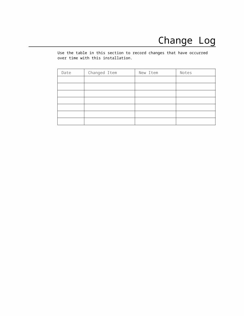
Change LogUse the table in this section to record changes that have occurred over time with this installation.
Date Changed Item New Item Notes

Using This DocumentationThis guide provides the configuration worksheets that must be completed before receiving Oracle SuperCluster M8 or SuperCluster M7. There are two intended audiences for this document:
Customers who purchased SuperCluster M8 or SuperCluster M7 and will have the system installed at their site. Customers should use this document to provide customer-specific networking information that is necessary for a successful installation of the system.
Oracle installers who will be configuring the system at the customer site. Oracle installers should refer to the networking information that was provided by the customer in this document and input that information into the appropriate configuration utility.
Product Documentation LibraryDocumentation and resources for this product and related products are available at http://www.oracle.com/goto/sc-m7/docs.
FeedbackProvide feedback about this documentation at http://www.oracle.com/goto/docfeedback.
8 Oracle SuperCluster M8 and SuperCluster M7 Configuration Worksheets • December 2017

Chapter
1Understanding the Configuration
WorksheetsThis document helps define SuperCluster M8 or SuperCluster M7 configuration settings for your environment.
Working with the network and database administrators, evaluate the current environmental settings, such as current IP address use and network configuration. Next, define the settings for SuperCluster M8 or SuperCluster M7, such as network configuration and backup method.
This document includes the configuration worksheets for SuperCluster M8 or SuperCluster M7. The Oracle SuperCluster M8 and SuperCluster M7 Overview Guide and Oracle SuperCluster M8 and SuperCluster M7 Installation Guide contain additional information, such as site requirements.
The information is used to create the SuperCluster M8 or SuperCluster M7 Installation Template. You must complete the worksheets and provide them to your Oracle representative prior to installation.
All information is required unless otherwise indicated. Oracle installers use the Installation Template to complete installation and configuration of your system. Site-specific adjustments to the Installation Template must be made in consultation with your Oracle representative.
Note - Complete the configuration worksheets early in the process, and prior to receiving your SuperCluster M8 or SuperCluster M7, so that site-specific adjustments to the Installation Template do not delay installation.
Note - If you have purchased more than one SuperCluster M8 or SuperCluster M7 and you do not plan to cable them together, then you must complete one set of worksheets for each system.
9

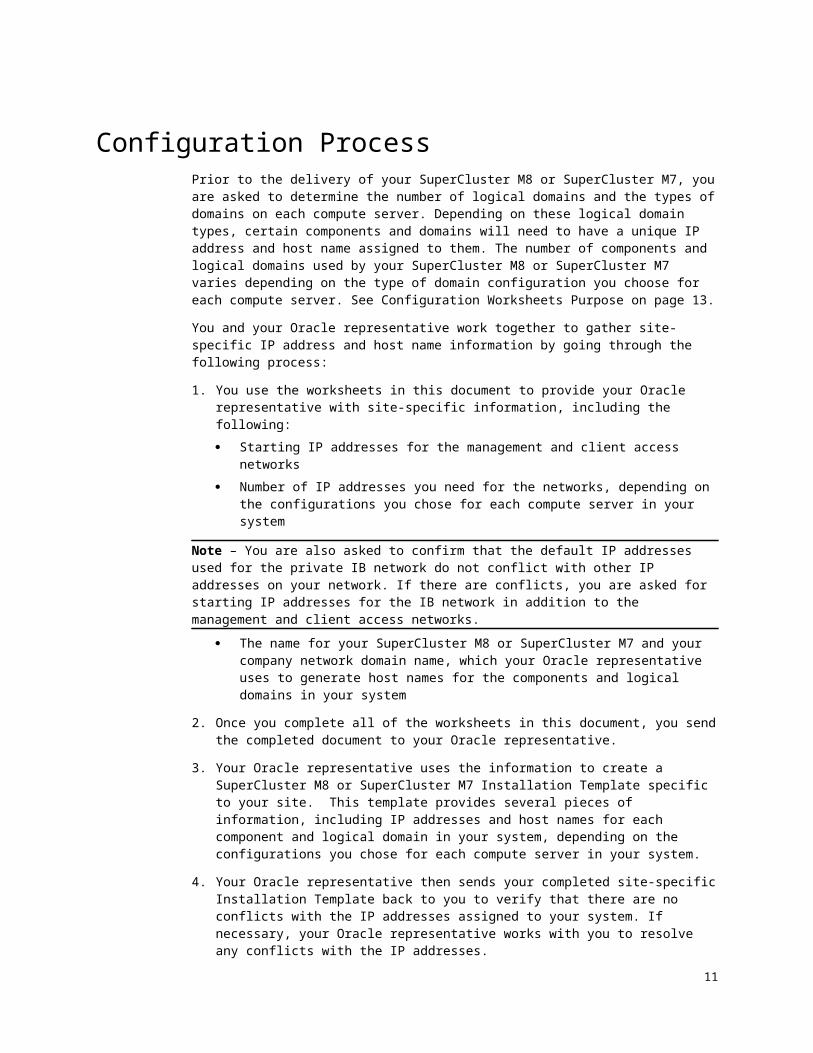
Configuration ProcessPrior to the delivery of your SuperCluster M8 or SuperCluster M7, you are asked to determine the number of logical domains and the types of domains on each compute server. Depending on these logical domain types, certain components and domains will need to have a unique IP address and host name assigned to them. The number of components and logical domains used by your SuperCluster M8 or SuperCluster M7 varies depending on the type of domain configuration you choose for each compute server. See Configuration Worksheets Purpose on page 11.
You and your Oracle representative work together to gather site-specific IP address and host name information by going through the following process:
1. You use the worksheets in this document to provide your Oracle representative with site-specific information, including the following: Starting IP addresses for the management and client access networks Number of IP addresses you need for the networks, depending on the
configurations you chose for each compute server in your system
Note – You are also asked to confirm that the default IP addresses used for the private IB network do not conflict with other IP addresses on your network. If there are conflicts, you are asked for starting IP addresses for the IB network in addition to the management and client access networks.
The name for your SuperCluster M8 or SuperCluster M7 and your company network domain name, which your Oracle representative uses to generate host names for the components and logical domains in your system
2. Once you complete all of the worksheets in this document, you send the completed document to your Oracle representative.
3. Your Oracle representative uses the information to create a SuperCluster M8 or SuperCluster M7 Installation Template specific to your site. This template provides several pieces of information, including IP addresses and host names for each component and logical domain in your system, depending on the configurations you chose for each compute server in your system.
4. Your Oracle representative then sends your completed site-specific Installation Template back to you to verify that there are no conflicts with the IP addresses assigned to your system. If necessary, your Oracle representative works with you to resolve any conflicts with the IP addresses.
5. Once the Installation Template is complete and all IP address conflicts have been resolved, you use the information in the Installation Template to register the IP addresses and host names in DNS. All IP addresses and host names for your system must be registered in DNS before your SuperCluster M8 or SuperCluster M7 can be installed at your site.
Note - All IP addresses must be statically-assigned IP addresses, not dynamically-assigned (DHCP) addresses.
10 Oracle SuperCluster M8 and SuperCluster M7 Configuration Worksheets • December 2017
Configuration Worksheets PurposeWhen you order SuperCluster M8 or SuperCluster M7, you are asked to make the following configuration choices:
Number of compute servers (1 or 2) Number of populated PDomains in each compute server Number of CMIOUs in each PDomain (1 to 4)
Before SuperCluster M8 or SuperCluster M7 can be shipped to your site, you must also provide to Oracle several pieces of information specific to your system, including:
Number of logical domains on each compute server, depending on the type of SuperCluster M8 or SuperCluster M7 that you have:
PDomains with one CMIOU: 1 logical domain (only available option)
PDomains with two CMIOUs: 1 to 2 logical domains PDomains with three CMIOUs: 1 to 3 logical domains PDomains with four CMIOUs: 1 to 4 logical domains
Type of logical domains on each compute server: Application Domain running the Oracle Solaris 11 OS
(dedicated domain)1
Database Domain (dedicated domain) Root Domain
Note – The Database Domain (dedicated domain) can also be in two states, with zones or without zones.
Number of client access networks, VLAN tags and network recipes for the logical domains
For Database Domains and database zones, the number of Oracle RAC instances
Amount of CPU and memory resources allocated to each logical domain on each compute server
Starting IP addresses and number of IP addresses available for these networks:
Management network 10GbE client access network IB network Backup/Data Guard network, if applicable
Use the configuration worksheets in this document to provide Oracle this infor-mation.
1 You cannot have an Application Domain running Oracle Solaris 10 in SuperCluster M7. However, you can have Oracle Solaris 10 branded zones in Application Domains running Oracle Solaris 11 or Database Domains.
11

Chapter
1Understanding PDomain
ConfigurationsThere are several PDomain configurations to choose from, depending on the following factors:
The number of compute servers in SuperCluster M8 or SuperCluster M7 The number of PDomains in each compute server The number of CMIOUs in each PDomain
This chapter provides information on the PDomain configurations available: Single Compute Server Configurations (R1 PDomain Configurations) on
page 12 Dual Compute Server Configurations (R2 PDomain Configurations) on
page 13
Single Compute Server Configurations (R1 PDomain Configurations)
The R1-1 PDomain configuration is the only available configuration for the R1 PDomain configuration.
12 Oracle SuperCluster M8 and SuperCluster M7 Configuration Worksheets • December 2017

CMIOUs in Both PDomains in One Compute Server (R1-1 PDomain Configuration)The R1-1 PDomain configuration has these characteristics:
Two populated PDomains in a single compute server One to four CMIOUs in each PDomain
This figure shows the CMIOU slots on each PDomain in this configuration.
Dual Compute Server Configurations (R2 PDomain Configurations)
The R2 configurations are available for a SuperCluster M8 or SuperCluster M7 with two compute servers.
These choices are available for the R2 PDomain configuration, depending on which PDomains are populated with CMIOUs:
CMIOUs in Both PDomains in Both Compute Servers (R2-1 PDomain Configuration) on page 14
CMIOUs in PDomain 0 in Both Compute Servers (R2-2 PDomain Configuration) on page 14
CMIOUs in PDomain 0 in Compute Server 1, and in PDomains 0 and 1 in Compute Server 2 (R2-3 PDomain Configuration) on page 14
CMIOUs in PDomain 0 and 1 in Compute Server 1, and in PDomain 0 in Compute Server 2 (R2-4 PDomain Configuration) on page 15
13

CMIOUs in Both PDomains in Both Compute Servers (R2-1 PDomain Configuration)The R2-1 PDomain configuration has these characteristics:
Four populated PDomains across two compute servers One to four CMIOUs in each populated PDomain
This figure shows the CMIOU slots on each PDomain in this configuration.
CMIOUs in PDomain 0 in Both Compute Servers (R2-2 PDomain Configuration)The R2-2 PDomain configuration has these characteristics:
Two populated PDomains across two compute servers One to four CMIOUs in each populated PDomain
This figure shows the CMIOU slots on each PDomain in this configuration.
CMIOUs in PDomain 0 in Compute Server 1, and in PDomains 0 and 1 in Compute Server 2 (R2-3 PDomain Configuration) The R2-3 PDomain configuration has these characteristics
14 Oracle SuperCluster M8 and SuperCluster M7 Configuration Worksheets • December 2017

Populated PDomain 0 in compute server 1, and populated PDomains 0 and 1 in compute server 2
One to four CMIOUs in each populated PDomain
This figure shows the CMIOU slots on each PDomain in this configuration.
CMIOUs in PDomain 0 and 1 in Compute Server 1, and in PDomain 0 in Compute Server 2 (R2-4 PDomain Configuration) The R2-4 PDomain configuration has these characteristics:
Populated PDomains 0 and 1 in compute server 1, and populated PDomain 0 in compute server 2
One to four CMIOUs in each populated PDomain
This figure shows the CMIOU slots on each PDomain in this configuration.
What’s NextGo to PDomain Configuration Worksheets on page 16 to complete the worksheets for the PDomain configuration.
15

Chapter
1PDomain Configuration Worksheets
Complete the worksheets in this chapter to provide overall PDomain configuration information. Refer to the Oracle SuperCluster M8 and SuperCluster M7 Overview Guide for more information on the PDomain configurations.
System-Level PDomain Configurations on page 16 Compute Server-Level PDomain Configurations on page 18
System-Level PDomain ConfigurationsProvide the system-level PDomain configuration information in this table.
Table 1 -- System-Level PDomain Configuration Worksheet
Item Entry Description and Example
Upper level PDomain configuration
Upper level PDomain configuration that you will have for your SuperCluster M8 or SuperCluster M7. Options: R1 or R2.
Second level PDomain configuration
Second level PDomain configuration that you will have for your SuperCluster M8 or SuperCluster M7.Options:
R1-1
R2-1 R2-2 R2-3 R2-4
16 Oracle SuperCluster M8 and SuperCluster M7 Configuration Worksheets • December 2017

17

Compute Server-Level PDomain Configurations
Provide the compute server-level PDomain configuration information in these sections.
Number of CMIOUs in PDomains in Compute Server 1 on page 18 Number of CMIOUs in PDomains in Compute Server 2 on page 18
Number of CMIOUs in PDomains in Compute Server 1Provide information on the number of CMIOUs that you will have in each PDomain in compute server 1.
Table 2 -- Compute Server 1 PDomain Configuration Worksheet
Item Entry Description and Example
Number of CMIOUs in PDomain 0
The number of CMIOUs that you will have in PDomain 0 in compute server 1.Options: 1, 2, 3 or 4.
Number of CMIOUs in PDomain 1
The number of CMIOUs that you will have in PDomain 1 in compute server 1.Options: 0, 1, 2, 3 or 4.
Number of CMIOUs in PDomains in Compute Server 2Provide information on the number of CMIOUs that you will have in each PDomain in compute server 2.
Table 3 -- Compute Server 2 PDomain Configuration Worksheet
Item Entry Description and Example
Number of CMIOUs in PDomain 0
The number of CMIOUs that you will have in PDomain 0 in compute server 2.Options: 1, 2, 3 or 4.
Number of CMIOUs in PDomain 1
The number of CMIOUs that you will have in PDomain 1 in compute server 2.Options: 0, 1, 2, 3 or 4.
18 Oracle SuperCluster M8 and SuperCluster M7 Configuration Worksheets • December 2017

What’s NextGo to Understanding LDom Configuration on page 20.
19

Chapter
1Understanding LDom Configurations
You must decide on the number of CMIOUs that you want set up in each PDomain in each compute server in your SuperCluster M8 or SuperCluster M7 before you can decide on the LDom configurations for each PDomain.
This chapter provides information on the LDom configurations available, depending on the number of CMIOUs set up in each PDomain.
Oracle Setup of Database Zones and I/O Domains Overview on page 20 General LDom Configuration Guidelines on page 21 LDom Configurations For PDomains With One CMIOU on page 22 LDom Configurations For PDomains With Two CMIOUs on page 22 LDom Configurations For PDomains With Three CMIOUs on page 24 LDom Configurations For PDomains With Four CMIOUs on page 26
Oracle Setup of Database Zones and I/O Domains Overview
As part of a typical initial installation of your SuperCluster, the Oracle installer sets up any dedicated domains (Database Domains or Application Domains) and any Root Domains that will be part of your SuperCluster configuration.
Additionally, your Oracle installer can configure a combination of up to eight of these items:
Database zones (zones hosted on Database Domains that are dedicated domains)
I/O Domains (either Application I/O Domains or Database I/O Domains)
For example, as part of the initial installation of your Oracle SuperCluster, you could have your Oracle installer set up four database zones and four I/O Domains, or two database zones and six I/O Domains.
20 Oracle SuperCluster M8 and SuperCluster M7 Configuration Worksheets • December 2017

General LDom Configuration GuidelinesFollowing are the general configuration guidelines for SuperCluster M8 and SuperCluster M7:
When deciding which logical domains will be a Root Domain, the last domain must always be the first Root Domain.
Only Database Domains that are dedicated domains can host database zones. If you want database zones on your Database Domains, you must select the Database Domain (dedicated domain) in order to have database zones.
A logical domain cannot be a Root Domain if it has more than two IB HCAs associated with it. In a SuperCluster M8 or SuperCluster M7, each CMIOU installed in a chassis has one IB HCA installed in PCIe slot 3.
For PDomains with three CMIOUs, the U3-1 LDom configuration has only one LDom, which spans across all three CMIOUs. Therefore, that logical domain cannot be a Root Domain.
For PDomains with four CMIOUs, the U4-1 LDom configuration has only one LDom, which spans across all four CMIOUs. Therefore, that logical domain cannot be a Root Domain.
All other logical domains in all other LDom configurations can be Root Domains because all other logical domains have only one or two CMIOUs associated with them.
Note - Even though a logical domain with two IB HCAs is valid for a Root Domain, logical domains with only one IB HCA should be used as Root Domains. When a Root Domain has a single IB HCA, fewer I/O Domains will have dependencies on the I/O devices provided by that Root Domain. Flexibility around high availability also increases with Root Domains with one IB HCA.
If you have a mixture of dedicated domains and Root Domains, the following rules apply when reallocating CPU and memory resources after the initial installation and after I/O Domains have been created:
o You can reallocate CPU and memory resources between dedicated domains.
o You can park CPU and memory resources that were allocated to dedicated domains. Those parked core and memory resources are now available for future I/O Domains that you create through the SuperCluster Virtual Assistant.
o Once you have parked CPU and memory resources from dedicated domains, you cannot unpark them and reallocate them back to the dedicated domains once you begin creating I/O Domains. Once you begin creating I/O Domains, any parked CPU and memory resources are now used exclusively for I/O Domains and are no longer available for dedicated domains.
o You cannot reallocate CPU and memory resources for Root Domains after the initial installation.
See Understanding CPU Resource Allocation on page 28 and Understanding Memory Resource Allocation on page 38 for more information.
You provide configuration information in this document telling your
21

Oracle installer whether you want Root Domains or dedicated domains at the time of the initial installation. After the initial installation, you will be able to create I/O Domains that access the Root Domains using the SuperCluster Virtual Assistant. While you do not provide information on the I/O Domains in this document, you should consider the size of the I/O Domains that you will be creating before deciding on Root Domains or dedicated domains. You should not create I/O Domains that are larger than one socket, so if you were planning to create I/O Domains that are that large, you should not choose a Root Domain and you should choose a dedicated domain instead.
LDom Configurations For PDomains With One CMIOU
A single LDom is the only valid LDom configuration for PDomains with one CMIOU.
This LDom can be any of the following domain types: Application Domain running the Oracle Solaris 11 OS (dedicated domain) Database Domain (dedicated domain), with or without zones2
Root Domain, with some I/O Domains set up at the initial installation2
ExampleFor this PDomain, assume you want a Database Domain that contains zones (DB-Z), with the Oracle installer setting up four database zones. For this configuration, you would fill out the configuration information for that server in this way:
Type of Domain on Compute Server 1
DB-Z: 4 zones
LDom Configurations For PDomains With Two CMIOUs
These configurations are available for PDomains with two CMIOUs:
2 See Oracle Setup of Database Zones and I/O Domains Overview on page 20 for more information on the maximum number of database zones and I/O Domains that can be set up by your Oracle installer.22 Oracle SuperCluster M8 and SuperCluster M7 Configuration Worksheets • December 2017

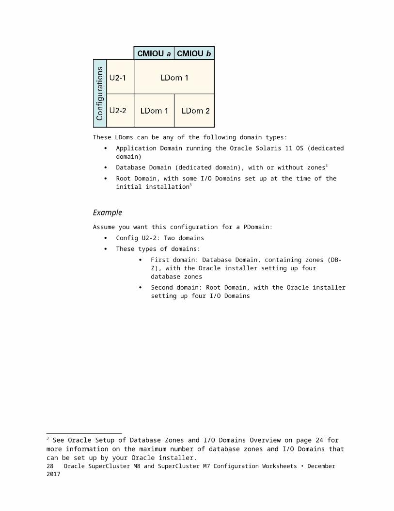
Config U2-1: One domain Config U2-2: Two domains
The following figure shows these available configurations for the PDomains with two CMIOUs.
These LDoms can be any of the following domain types: Application Domain running the Oracle Solaris 11 OS (dedicated domain) Database Domain (dedicated domain), with or without zones3
Root Domain, with some I/O Domains set up at the time of the initial installation3
ExampleAssume you want this configuration for a PDomain:
Config U2-2: Two domains These types of domains:
First domain: Database Domain, containing zones (DB-Z), with the Oracle installer setting up four database zones
Second domain: Root Domain, with the Oracle installer setting up four I/O Domains
3 See Oracle Setup of Database Zones and I/O Domains Overview on page 20 for more information on the maximum number of database zones and I/O Domains that can be set up by your Oracle installer.
23

For this configuration, you would fill out the configuration information for that PDomain in this way:
Number and Type of Domains on PDomain 0
Check One Box Config One Two
U2-1
X U2-2 DB-Z: 4 zones ROOT: 4 I/O Domains
LDom Configurations For PDomains With Three CMIOUs
These configurations are available for PDomains with three CMIOUs: Config U3-1: One domain Config U3-2: Two domains Config U3-3: Three domains
This figure shows these available configurations for the PDomains with three CMIOUs.
Keeping in mind the domain configuration rules outlined in General LDom Configuration on page 21, the domain in the U3-1 LDom configuration cannot be a Root Domain. All other domains can be any of these domain types:
Application Domain running the Oracle Solaris 11 OS (dedicated domain) Database Domain (dedicated domain), with or without zones4
Root Domain, with some I/O Domains set up at the initial installation5
4 See Oracle Setup of Database Zones and I/O Domains Overview on page 20 for more information on the maximum number of database zones and I/O Domains that can be set up by your Oracle installer.24 Oracle SuperCluster M8 and SuperCluster M7 Configuration Worksheets • December 2017

ExampleAssume you want this configuration for a PDomain:
Config U3-3: Three domains These types of domains:
First domain: Database Domain, containing zones (DB-Z), with the Oracle installer setting up four zones
Second domain: Database Domain, where the Database Domain does not contain zones (DB)
Third domain: Root Domain, with the Oracle installer setting up four I/O Domains
For this configuration, you would fill out the configuration information for that PDomain in this way:
Number and Type of LDoms on PDomain One in Compute Server 1
Check One Box Config One Two Three
U3-1
U3-2
X U3-3
DB-Z: 4 zones DB ROOT: 4 I/O Domains
25

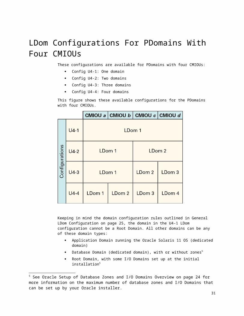
LDom Configurations For PDomains With Four CMIOUs
These configurations are available for PDomains with four CMIOUs: Config U4-1: One domain Config U4-2: Two domains Config U4-3: Three domains Config U4-4: Four domains
This figure shows these available configurations for the PDomains with four CMIOUs.
Keeping in mind the domain configuration rules outlined in General LDom Configuration on page 21, the domain in the U4-1 LDom configuration cannot be a Root Domain. All other domains can be any of these domain types:
Application Domain running the Oracle Solaris 11 OS (dedicated domain) Database Domain (dedicated domain), with or without zones5
Root Domain, with some I/O Domains set up at the initial installation5
ExampleAssume you want this configuration for a PDomain:
Config U4-3: Three domains These types of domains:
First domain: Database Domain, containing zones (DB-Z), with
5 See Oracle Setup of Database Zones and I/O Domains Overview on page 20 for more information on the maximum number of database zones and I/O Domains that can be set up by your Oracle installer.26 Oracle SuperCluster M8 and SuperCluster M7 Configuration Worksheets • December 2017

the Oracle installer setting up four zones Second domain: Database Domain, where the Database
Domain does not contain zones (DB) Third domain: Root Domain, with the Oracle installer setting
up four I/O Domains
For this configuration, you would fill out the configuration information for that PDomain in this way:
Number and Type of LDoms on PDomain One in Compute Server 1
Check One Box Config One Two Three Four
U4-1
U4-2
X U4-3
DB-Z: 4 zones DB ROOT: 4 I/O Domains
U4-4
What’s NextGo to Understanding CPU Resource Allocation on page 28.
LDom Configurations: PDomains with 8 CMIOUs
27
Chapter
1Understanding CPU Resource
AllocationThis chapter provides information on allocating CPU resources for the LDoms:
CPU Resources Overview on page 28 CPU Cores Available for Database Zones and I/O Domains on page 29 CPU Resource Allocation For PDomains With One CMIOU on page 31 CPU Resource Allocation For PDomains With Two CMIOUs on page 32 CPU Resource Allocation For PDomains With Three CMIOUs on page 33 CPU Resource Allocation For PDomains With Four CMIOUs on page 35
CPU Resources OverviewThe amount of CPU resources available for the LDoms varies, depending on the following factors:
The number of CMIOUs in each server The number of CMIOUs in each PDomain The type of PDomain configuration that you want on each compute server The type of LDom configuration that you want on each PDomain
As described in General LDom Configuration on page 21, if you have a mixture of dedicated domains and Root Domains, after the initial installation, you can reallocate CPU resources only with the dedicated domains. You cannot reallocate CPU resources for Root Domains after the initial installation.
Because resources allocated to Root Domains at the initial installation cannot be used by dedicated domains, carefully consider the amount of CPU resources that you want to have allocated to Root Domains at the time of the initial installation. In addition, once you have parked CPU resources from the dedicated domains, you cannot unpark them and reallocate them back to the dedicated domains after the initial installation.
28 Oracle SuperCluster M8 and SuperCluster M7 Configuration Worksheets • December 2017

CPU Cores Available for Database Zones and I/O Domains
Note – See Oracle Setup of Database Zones and I/O Domains Overview on page 20 for more information on the maximum number of database zones and I/O Domains that can be set up by your Oracle installer.
Every CMIOU has 32 cores of CPU resources. The amount of CPU resources available for each domain varies, depending on the number of CMIOUs that are associated with that domain.
These sections provide more information on the CPU cores available for database zones and I/O Domains:
CPU Cores Available for Database Zones on page 29 CPU Cores Available for I/O Domains on page 30
CPU Cores Available for Database ZonesNote – Database zones can only be created on Database Domains that are dedicated domains. The information in this section applies to database zones and Database Domains that are dedicated domains.
When you first install the operating system instances on a domain, that domain is automatically designated as the global zone. When creating zones on Database Domains, the Database Domain is designated as the global zone, and the zones created on that Database Domain are designated as nonglobal zones.
A certain number of cores are always set aside for the global zone (the Database Domain). The remaining cores in the Database Domain are available for the nonglobal zones (the zones in the Database Domain). The number of cores that are set aside for the global zone varies, depending on the number of CMIOUs that are associated with the domain:
One CMIOU associated with an LDom: 2 cores are reserved for the global zone, and the remaining cores are available for the nonglobal zones.
Two or more CMIOUs associated with an LDom: 4 cores are reserved for the global zone, and the remaining cores are available for the nonglobal zones.
When using the information above, keep in mind that the number of cores that are set aside for the global zone applies only when you are creating zones (nonglobal zones) on that Database Domain. In that case, a certain number of cores are reserved for the Database Domain (the global zone) and the remaining cores are available for the zones on that Database Domain (the nonglobal zones). If you have a Database Domain with no zones, then all the cores are available for that Database Domain.
For each zone that you create, use a minimum of one core per zone. However, depending on the workload that you expect on a zone, a larger number of cores per zone might be preferable, thereby reducing the total number of zones on each compute server. Carefully consider the expected workload on each zone that you create, so that you allot the appropriate number of cores to those zones.
29

CPU Cores Available for I/O DomainsIf you want I/O Domains set up on your Oracle SuperCluster, either at the time of the initial installation or afterwards, you must have at least one Root Domain set up at the time of the initial installation. I/O Domains can then be created from these Root Domains.
A certain number of CPU cores are always reserved for each Root Domain, depending on which domain is being used as a Root Domain in the domain configuration and the number of IB HCAs and 10GbE NICs that are associated with that Root Domain:
The last domain in a domain configuration: Two cores reserved for a Root Domain with one IB HCA and
10GbE NIC Four cores reserved for a Root Domain with two IB HCAs and
10GbE NICs Any other domain in a domain configuration:
One core reserved for a Root Domain with one IB HCA and 10GbE NIC
Two cores reserved for a Root Domain with two IB HCAs and 10GbE NICs
The remaining CPU core resources allocated with each Root Domain are parked in the CPU repository, which can then be used by I/O Domains.
Note – For more information on the number of IB HCAs and 10GbE NICs associated with each domain, refer to the Oracle SuperCluster M8 and SuperCluster M7 Overview Guide.
The CPU repository contains resources not only from the Root Domains, but also any parked resources from the dedicated domains. Whether the CPU core resources originated from dedicated domains or from Root Domains, once those resources have been parked in the CPU repository, those resources are no longer associated with their originating domain. These resources become equally available to I/O Domains.
In addition, the CPU repository contains parked resources only from the compute server that contains the domains providing those parked resources. In other words, if you have two compute servers and both compute servers have Root Domains, there would be two sets of CPU repositories, where each compute server would have its own CPU repository with parked resources.
For example, assume you have four domains on your compute server, with three of the four domains as Root Domains. Assume each domain has the following:
One IB HCA and one 10GbE NIC 32 cores
In this situation, the following CPU resources are reserved for each Root Domain, with the remaining resources available for the CPU repository:
Two cores reserved for the last Root Domain in this configuration. 30 cores available from this Root Domain for the CPU repository.
One core reserved for the second and third Root Domains in this configuration.
31 cores available from each of these Root Domains for the CPU repository.
A total of 62 cores (31 x 2) available for the CPU repository
30 Oracle SuperCluster M8 and SuperCluster M7 Configuration Worksheets • December 2017
from these two Root Domains.
A total of 92 cores (30 + 62) are therefore parked in the CPU repository and are available for the I/O Domains.
CPU Resource Allocation For PDomains With One CMIOU
For PDomains with one CMIOU, each PDomain has a total of 32 cores of CPU resources.
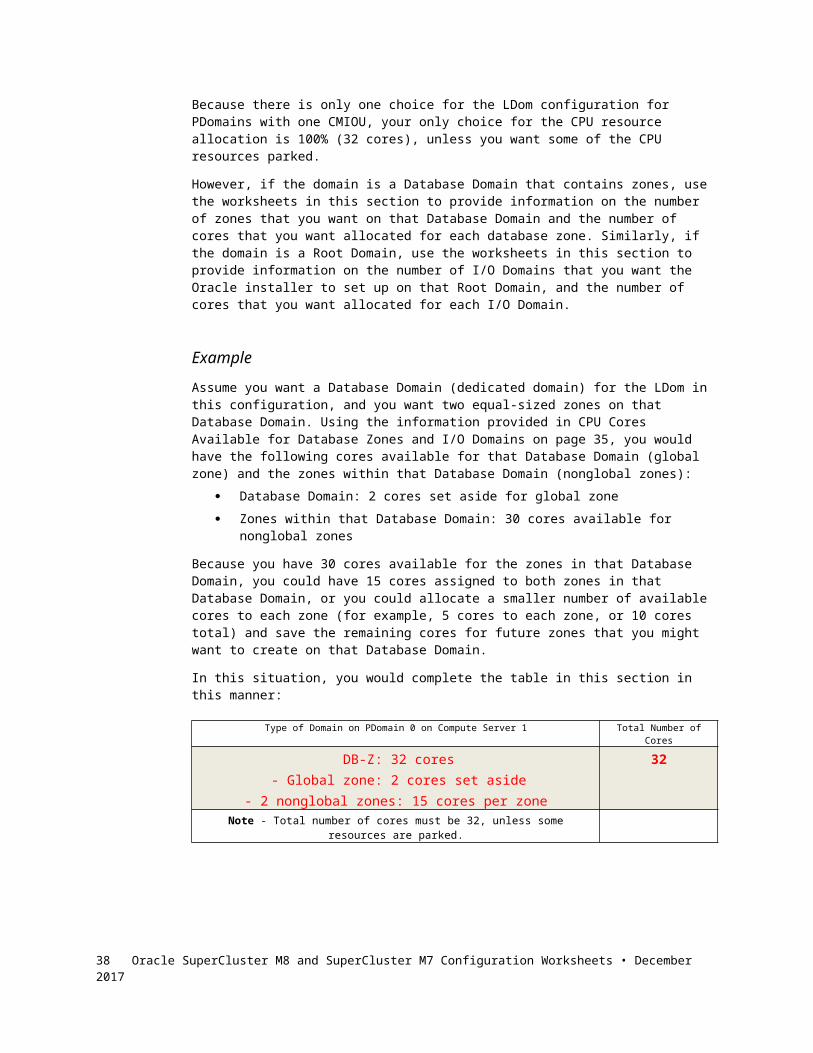
Because there is only one choice for the LDom configuration for PDomains with one CMIOU, your only choice for the CPU resource allocation is 100% (32 cores), unless you want some of the CPU resources parked.
However, if the domain is a Database Domain that contains zones, use the worksheets in this section to provide information on the number of zones that you want on that Database Domain and the number of cores that you want allocated for each database zone. Similarly, if the domain is a Root Domain, use the worksheets in this section to provide information on the number of I/O Domains that you want the Oracle installer to set up on that Root Domain, and the number of cores that you want allocated for each I/O Domain.
ExampleAssume you want a Database Domain (dedicated domain) for the LDom in this configuration, and you want two equal-sized zones on that Database Domain. Using the information provided in CPU Cores Available for Database Zones and I/O Domains on page 29, you would have the following cores available for that Database Domain (global zone) and the zones within that Database Domain (nonglobal zones):
Database Domain: 2 cores set aside for global zone Zones within that Database Domain: 30 cores available for nonglobal
zones
Because you have 30 cores available for the zones in that Database Domain, you could have 15 cores assigned to both zones in that Database Domain, or you could allocate a smaller number of available cores to each zone (for example, 5 cores to each zone, or 10 cores total) and save the remaining cores for future zones that you might want to create on that Database Domain.
In this situation, you would complete the table in this section in this manner:
Type of Domain on PDomain 0 on Compute Server 1 Total Number of Cores
DB-Z: 32 cores- Global zone: 2 cores set aside
- 2 nonglobal zones: 15 cores per zone
32
Note - Total number of cores must be 32, unless some resources are parked.
31

CPU Resource Allocation For PDomains With Two CMIOUs
For PDomains with two CMIOUs, each PDomain has a total of 64 cores of CPU resources.
Note – As described in General LDom Configuration on page 21, if you have a mixture of dedicated domains and Root Domains, after the initial installation, you can reallocate CPU resources only with the dedicated domains. You cannot reallocate CPU resources for Root Domains after the initial installation.
Because Root Domains cannot be resized or have resources reallocated (parked) after the initial installation, carefully consider the amount of CPU resources that you want to have allocated to Root Domains when entering information in the following tables.
ExampleAssume you want Configuration U2-2 for the PDomain (two LDoms). You could assign 50% of the CPU resources to each domain, or you could assign different values to each domain, such as 40% of the CPU resources to the first domain and 60% to the second domain.
In addition, assume the first domain is a Database Domain that contains zones, and you want four equal-sized zones on that Database Domain. Using the information provided in CPU Cores Available for Database Zones and I/O Domains on page 29, and assuming you assigned 50% of the CPU and memory resources to each domain, you would have 32 cores available for the first domain, and you would have the following cores available for that Database Domain (global zone) and the zones within that Database Domain (nonglobal zones):
Database Domain: 2 cores set aside for global zone Zones within that Database Domain: 30 cores available for nonglobal
zones
Because you have 30 cores available for the zones in that Database Domain, you could have eight cores assigned to the first two zones and seven cores assigned to the other two zones within that Database Domain, or you could allocate a smaller number of available cores to each zone (for example, five cores to each zone, or 20 cores total) and save the remaining cores for future zones that you might want to create on that Database Domain.
Similarly, assume the second domain is a Root Domain, with the Oracle installer setting up four I/O Domains at the initial installation of the system. Using the information provided in CPU Cores Available for Database Zones and I/O Domains on page 29, and assuming you assigned 50% of the CPU resources to each domain, you would have 32 cores available for the second domain, and you would have the following cores available for that Root Domain and I/O Domains:
Root Domain: 2 cores set aside for the Root Domain I/O Domains: 30 cores available for the I/O Domains
Note – Additional cores could be available for I/O Domains if cores from other domains were parked. For the purposes of this exercise, however, we are assuming that no other cores from other domains are parked, and the remaining 30 cores from this Root Domain are the only cores available for the I/O Domains.
32 Oracle SuperCluster M8 and SuperCluster M7 Configuration Worksheets • December 2017

Because you have 30 cores available for I/O Domains, you could create I/O Domains similar to the way you created database zones, where you could have eight cores assigned to the first two I/O Domains (16 cores for both) and seven cores assigned to the other two I/O Domains (14 cores for both), for a total of 30 cores. Or you could allocate a smaller number of available cores to each I/O Domain (for example, five cores to each I/O Domain, or 20 cores total), and save the remaining cores for future I/O Domains that you might want to create on that Root Domain.
Assuming you wanted to allocate five cores to each database zone and five cores to each I/O Domain, you would complete the table in this section in this manner:
Check One Box
Config
CPU Resource Allocation for PDomain 0 in Compute Server 1Total Number of
CoresOne Two
U2-1
X U2-2
DB-Z: 32 cores- Global zone: 2 cores set aside
- 4 nonglobal zones: 5 cores per zone
ROOT: 32 cores- Root Domain: 2 cores set aside
- 4 I/O Domains: 5 cores per I/O
Domain
64
Note - Total number of cores must be 64, unless some resources are parked.
CPU Resource Allocation For PDomains With Three CMIOUs
For PDomains with three CMIOUs, each PDomain has a total of 96 cores of CPU resources.
Note – As described in General LDom Configuration on page 21, if you have a mixture of dedicated domains and Root Domains, after the initial installation, you can reallocate CPU resources only with the dedicated domains. You cannot reallocate CPU resources for Root Domains after the initial installation.
Because Root Domains cannot be resized or have resources reallocated (parked) after the initial installation, carefully consider the amount of CPU resources that you want to have allocated to Root Domains when entering information in the following tables.
ExampleAssume you want Configuration U3-3 for the PDomain (three LDoms). You could assign 33% of the CPU resources to each of the three domains. Or you could assign different values to each domain, such as 50% of the CPU resources to the first domain and 25% to the second and third domains.
33

In addition, assume the first domain is a Database Domain that contains zones, and you want four equal-sized zones on that Database Domain. Using the information provided in CPU Cores Available for Database Zones and I/O Domains on page 29, and assuming you assigned 33% of the CPU and memory resources to the first domain (32 cores), you would have these cores available for that Database Domain (global zone) and the zones within that Database Domain (nonglobal zones):
Database Domain: 2 cores set aside for global zone Zones within that Database Domain: 30 cores available for nonglobal
zones
Because you have 30 cores available for the zones in that Database Domain, you could have eight cores assigned to the first two zones and seven cores assigned to the other two zones within that Database Domain, or you could allocate a smaller number of available cores to each zone (for example, five cores to each zone, or 20 cores total) and save the remaining cores for future zones that you might want to create on that Database Domain.
Similarly, assume the third (last) domain is a Root Domain, with the Oracle installer setting up four I/O Domains at the initial installation of the system. Using the information provided in CPU Cores Available for Database Zones and I/O Domains on page 29, and assuming you assigned 33% of the CPU resources to the third domain, you would have 32 cores available for the third domain, and you would have the following cores available for that Root Domain and I/O Domains:
Root Domain: 2 cores set aside for the Root Domain I/O Domains: 30 cores available for the I/O Domains
Note – Additional cores could be available for I/O Domains if cores from other domains were parked. For the purposes of this exercise, however, we are assuming that no other cores from other domains are parked, and the remaining 30 cores from this Root Domain are the only cores available for the I/O Domains.
Because you have 30 cores available for I/O Domains, you could create I/O Domains similar to the way you created database zones, where you could have eight cores assigned to the first two I/O Domains (16 cores for both) and seven cores assigned to the other two I/O Domains (14 cores for both), for a total of 30 cores. Or you could allocate a smaller number of available cores to each I/O Domain (for example, five cores to each I/O Domain, or 20 cores total), and save the remaining cores for future I/O Domains that you might want to create on that Root Domain.
34 Oracle SuperCluster M8 and SuperCluster M7 Configuration Worksheets • December 2017

Assuming you wanted to allocate five cores to each database zone and five cores to each I/O Domain, you would complete the table in this section in this manner:
CPU Resource Allocation for PDomain 0 in Compute Server 1
Check One Box Config One Two Three
Total Number of Cores
U3-1
U3-2
X U3-3
DB-Z: 32 cores- Global zone: 2 cores set aside
- 4 nonglobal zones: 5 cores per zone
DB: 32 cores ROOT: 32 cores- Root Domain: 2 cores set aside
- 4 I/O Domains: 5 cores per I/O
Domain
96
Note - Total number of cores must be 96, unless some resources are parked.
CPU Resource Allocation For PDomains With Four CMIOUs
For PDomains with four CMIOUs, each PDomain has a total of 128 cores of CPU resources.
Note – As described in General LDom Configuration on page 21, if you have a mixture of dedicated domains and Root Domains, after the initial installation, you can reallocate CPU resources only with the dedicated domains. You cannot reallocate CPU resources for Root Domains after the initial installation.
Because Root Domains cannot be resized or have resources reallocated (parked) after the initial installation, carefully consider the amount of CPU resources that you want to have allocated to Root Domains when entering information in the following tables.
ExampleAssume you want Configuration U4-3 for the PDomain (three LDoms). You could assign 50% of the CPU resources to the first domain and 25% to the second and third domains. Or you could assign different values to each domain, such as 40% of the CPU resources to the first domain and 30% to the second and third domains.
35

In addition, assume the first domain is a Database Domain that contains zones, and you want four equal-sized zones on that Database Domain. Using the information provided in CPU Cores Available for Database Zones and I/O Domains on page 29, and assuming you assigned 50% of the CPU and memory resources to the first domain (64 cores), you would have these cores available for that Database Domain (global zone) and the zones within that Database Domain (nonglobal zones):
Database Domain: 4 cores set aside for global zone Zones within that Database Domain: 60 cores available for nonglobal
zones
Because you have 60 cores available for the zones in that Database Domain, you could have 15 cores assigned to each of the four zones within that Database Domain, or you could allocate a smaller number of available cores to each zone (for example, 10 cores to each zone, or 40 cores total) and save the remaining cores for future zones that you might want to create on that Database Domain.
Similarly, assume the third (last) domain is a Root Domain, with the Oracle installer setting up four I/O Domains at the initial installation of the system. Using the information provided in CPU Cores Available for Database Zones and I/O Domains on page 29, and assuming you assigned 25% of the CPU resources to the third domain, you would have 32 cores available for the third domain, and you would have the following cores available for that Root Domain and I/O Domains:
Root Domain: 2 cores set aside for the Root Domain I/O Domains: 30 cores available for the I/O Domains
Note – Additional cores could be available for I/O Domains if cores from other domains were parked. For the purposes of this exercise, however, we are assuming that no other cores from other domains are parked, and the remaining 30 cores from this Root Domain are the only cores available for the I/O Domains.
Because you have 30 cores available for I/O Domains, you could create I/O Domains similar to the way you created database zones, where you could have eight cores assigned to the first two I/O Domains (16 cores for both) and seven cores assigned to the other two I/O Domains (14 cores for both), for a total of 30 cores. Or you could allocate a smaller number of available cores to each I/O Domain (for example, five cores to each I/O Domain, or 20 cores total), and save the remaining cores for future I/O Domains that you might want to create on that Root Domain.
36 Oracle SuperCluster M8 and SuperCluster M7 Configuration Worksheets • December 2017

Assuming you wanted to allocate 15 cores to each database zone and five cores to each I/O Domain, you would complete the table in this section in this manner:
CPU Resource Allocation for PDomain 0 in Compute Server 1
Check One Box Config One Two Three Four
Total Number of Cores
U4-1
U4-2
X U4-3
DB-Z: 64 cores- Global zone: 4 cores set aside- 4 nonglobal zones: 15 cores
per zone
DB: 32 cores ROOT: 32 cores- Root Domain:
2 cores set aside
- 4 I/O Domains: 5 cores per I/O
Domain
128
U4-4
Note - Total number of cores must be 128, unless some resources are parked.
What’s NextGo to Understanding Memory Resource Allocation on page 38.
37
Chapter
1Understanding Memory Resource
AllocationThis chapter provides information on allocating memory resources for the LDoms in your system.
Memory Resources Overview on page 38 Memory Available for Database Zones and I/O Domains on page 39 Memory Resource Allocation For PDomains With One CMIOU on page 41 Memory Resource Allocation For PDomains With Two CMIOUs on page
42 Memory Resource Allocation For PDomains With Three CMIOUs on page
43 Memory Resource Allocation For PDomains With Four CMIOUs on page
44
Memory Resources OverviewThe amount of memory resources that you have available for the LDoms in your system varies, depending on these factors:
The number of CMIOUs in each server The number of CMIOUs in each PDomain The type of PDomain configuration that you want on each compute server The type of LDom configuration that you want on each PDomain
As described in General LDom Configuration on page 21, if you have a mixture of dedicated domains and Root Domains, after the initial installation, you can reallocate memory resources only with the dedicated domains. You cannot reallocate memory resources for Root Domains after the initial installation.
Because resources allocated to Root Domains at the initial installation cannot be used by dedicated domains, carefully consider the amount of memory resources that you want to have allocated to Root Domains at the time of the initial installation. In addition, once you have parked memory resources from the dedicated domains, you cannot unpark them and reallocate them back to the dedicated domains after the initial installation.
38 Oracle SuperCluster M8 and SuperCluster M7 Configuration Worksheets • December 2017

Memory Available for Database Zones and I/O Domains
Note – See Oracle Setup of Database Zones and I/O Domains Overview on page 20 for more information on the maximum number of database zones and I/O Domains that can be set up by your Oracle installer...
Every CMIOU has 16 memory slots.
In SuperCluster M8, each CMIOU is fully populated with 64 GB DIMMs, for a total of 1 TB (1024 GB) of memory in each CMIOU, with 960 GB available after DIMM sparing.
In SuperCluster M7, each CMIOU is fully populated with 32 GB DIMMs, for a total of 512 GB of memory in each CMIOU, with 480 available after DIMM sparing.
The amount of memory available for each domain varies, depending on the number of CMIOUs that are associated with that domain.
These sections provide more information on the memory resources available for database zones and I/O Domains:
Memory Resources Available for Database Zones on page 39 Memory Resources Available for I/O Domains on page 39
Memory Resources Available for Database Zones Note – Database zones can only be created on Database Domains that are dedicated domains. The information in this section applies to database zones and Database Domains that are dedicated domains.
The amount of memory resources available for database zones depends on the amount of memory resources that you have assigned to the Database Domain, and then how you want to divide those memory resources up for the database zones within that Database Domain.
For example, assume you have a Database Domain that has two CMIOUs associated with it. By default, 960 GB of memory would be available to that Database Domain. You could therefore have four equal-sized database zones within that Database Domain, where each database zone has 200 GB of memory assigned to it, for a total of 800 GB of memory for all database zones. The remaining 160 GB of memory in this Database Domain could then be saved for future database zones that you might want to create on this Database Domain.
Memory Resources Available for I/O DomainsIf you want I/O Domains set up on your Oracle SuperCluster, either at the time of the initial installation or afterwards, you must have at least one Root Domain set up at the time of the initial installation. I/O Domains can then be created from these Root Domains.
A certain amount of memory resources are always reserved for each Root Domain, depending on which domain is being used as a Root Domain in the
39

domain configuration and the number of IB HCAs and 10GbE NICs that are associated with that Root Domain:
The last domain in a domain configuration: 32 GB of memory reserved for a Root Domain with one IB HCA
and 10GbE NIC 64 GB of memory reserved for a Root Domain with two IB
HCAs and 10GbE NICs Any other domain in a domain configuration:
16 GB of memory reserved for a Root Domain with one IB HCA and 10GbE NIC
32 GB of memory reserved for a Root Domain with two IB HCAs and 10GbE NICs
The remaining memory resources allocated with each Root Domain are parked in the memory repository, which can then be used by I/O Domains.
Note – For more information on the number of IB HCAs and 10GbE NICs associated with each domain, refer to the Oracle SuperCluster M8 and SuperCluster M7 Overview Guide.
The memory repository contains resources not only from the Root Domains, but also any parked resources from the dedicated domains. Whether memory resources originated from dedicated domains or from Root Domains, once those resources have been parked in the memory repository, those resources are no longer associated with their originating domain. These resources become equally available to I/O Domains.
In addition, the memory repository contains parked resources only from the compute server that contains the domains providing those parked resources. In other words, if you have two compute servers and both compute servers have Root Domains, there would be two sets of memory repositories, where each compute server would have its own memory repository with parked resources.
For example, assume you have four domains on your compute server, with three of the four domains as Root Domains. Assume each domain has the following:
One IB HCA and one 10GbE NIC 480 GB of memory
In this situation, the following memory resources are reserved for each Root Domain, with the remaining resources available for the memory repository:
32 GB of memory reserved for the last Root Domain in this configuration. 448 GB of memory available from this Root Domain for the memory repository.
16 GB of memory reserved for the second and third Root Domains in this configuration.
464 GB of memory available from each of these Root Domains for the memory repository.
A total of 928 GB of memory (464 x 2) available for the memory repository from these two Root Domains.
A total of 1376 GB of memory (448 + 928) are therefore parked in the memory repository and are available for the I/O Domains.
40 Oracle SuperCluster M8 and SuperCluster M7 Configuration Worksheets • December 2017

Memory Resource Allocation For PDomains With One CMIOU
For PDomains with one CMIOU: In a SuperCluster M8, each PDomain has a total of 960 GB of available
memory resources. In a SuperCluster M7, each PDomain has a total of 480 GB of available
memory resources.
Because there is only one choice for the LDom configuration for PDomains with one CMIOU, your only choice for the memory resource allocation is 100% (480 GB), unless you want some of the memory resources parked.
However, if the domain is a Database Domain that contains zones, use the worksheets in this section to provide information on the number of zones for that Database Domain and the amount of memory resources that you want allocated for each database zone. Similarly, if the domain is a Root Domain, use the worksheets in this section to provide information on the number of I/O Domains that you want the Oracle installer to set up on that Root Domain, and the amount of memory resources that you want allocated for each I/O Domain.
ExampleAssume you have a SuperCluster M7 and you want a Root Domain for the LDom in this configuration, and you want four equal-sized I/O Domains on that Root Domain. Using the information provided in Memory Resources Available for I/O Domains on page 39, you would have the following amount of memory resources available for the Root Domain and the I/O Domains on that Root Domain:
32 GB of memory reserved for the Root Domain 448 GB of memory available for the I/O Domains
Because you have 448 GB of memory available for the I/O Domains, you could have 50 GB of memory assigned to each I/O Domain (200 GB of memory total) and save the remaining memory for future I/O Domains that you might want to create on that Root Domain.
In this situation, you would complete the table in this section in this manner:
Type of Domain on PDomain 0 on Compute Server 1 Total Amount of Memory
ROOT: 480 GB- Root: 32 GB set aside
- 4 I/O Domains: 50 GB per I/O Domain
480 GB
Note - Total amount of memory must be 960 GB (SuperCluster M8) or 480 GB (SuperCluster M7), unless some resources are parked.
41

Memory Resource Allocation For PDomains With Two CMIOUs
For PDomains with two CMIOUs: In a SuperCluster M8, each PDomain has a total of 1920 GB of available
memory resources. In a SuperCluster M7, each PDomain has a total of 960 GB of available
memory resources.
Note – As described in General LDom Configuration on page 21, if you have a mixture of dedicated domains and Root Domains, after the initial installation, you can reallocate memory resources only with the dedicated domains. You cannot reallocate memory resources for Root Domains after the initial installation.
Because Root Domains cannot be resized or have resources reallocated (parked) after the initial installation, carefully consider the amount of memory resources that you want to have allocated to Root Domains when entering information in the following tables.
ExampleAssume you have a SuperCluster M7 and you want Configuration U2-2 for the PDomain (two LDoms). You could assign 480 GB of memory resources to each domain.
Because you have 480 GB of memory available for the I/O Domains, you could have 50 GB of memory assigned to each I/O Domain (200 GB of memory total) and save the remaining memory for future I/O Domains that you might want to create on that Root Domain.
You would complete the table in this section in this manner in this situation:
Check One Box
Config
Memory Resource Allocation for PDomain 0 in Compute Server 1Total Amount of
MemoryOne Two
U2-1
X U2-2
DB-Z: 480 GB- 4 nonglobal zones:
100 GB per zone
ROOT: 480 GB- Root: 32 GB set
aside- 4 I/O Domains: 50 GB per I/O Domain
960 GB
Note - Total amount of memory resources must be 1920 GB (SuperCluster M8) or 960 GB (SuperCluster M7), unless some resources are parked.
42 Oracle SuperCluster M8 and SuperCluster M7 Configuration Worksheets • December 2017

Memory Resource Allocation For PDomains With Three CMIOUs
For PDomains with three CMIOUs In a SuperCluster M8, each PDomain has a total of 2880 of available
memory resources. In a SuperCluster M7, each PDomain has a total of 1440 GB of available
memory resources.
Note – As described in General LDom Configuration on page 21, if you have a mixture of dedicated domains and Root Domains, after the initial installation, you can reallocate memory resources only with the dedicated domains. You cannot reallocate memory resources for Root Domains after the initial installation.
Because Root Domains cannot be resized or have resources reallocated (parked) after the initial installation, carefully consider the amount of memory resources that you want to have allocated to Root Domains when entering information in the following tables.
ExampleAssume you have a SuperCluster M7 and you want Configuration U3-3 for the PDomain (three LDoms). You could assign 480 GB of memory resources to each domain.
In addition, assume the first domain is a Database Domain that contains zones, and you want four equal-sized zones on that Database Domain. Using the information provided in Memory Resources Available for Database Zones on page 39, you could have 100 GB of memory resources assigned to each database zone, for a total of 400 GB of memory for all four database zones. The remaining 80 GB of memory resources could then be saved for future database zones that you might want to create on this Database Domain.
Similarly, assume the third domain is a Root Domain, with the Oracle installer setting up four I/O Domains at the initial installation of the system. Using the information provided in Memory Resources Available for I/O Domains on page 39, you would have the following memory resources available for the Root Domain and the I/O Domains:
32 GB of memory reserved for the Root Domain 448 GB of memory available for the I/O Domains
Because you have 448 GB of memory available for the I/O Domains, you could have 50 GB of memory assigned to each I/O Domain (200 GB of memory total) and save the remaining memory for future I/O Domains that you might want to create on that Root Domain.
You would complete the table in this section in this manner in this situation:Memory Resource Allocation for PDomain 0 in Compute Server 1
Check One Box Config One Two Three
Total Number of Cores
U3-1
U3-2
43

X U3-3
DB-Z: 480 GB- 4 nonglobal zones:
100 GB per zone
DB: 460 GB ROOT: 480 GB- Root: 32 GB set
aside- 4 I/O Domains: 50 GB per I/O
1440 GB
Note - Total amount of memory resources must be 2880 GB (SuperCluster M8) or 1440 GB (SuperCluster M7), unless some resources are parked.
Memory Resource Allocation For PDomains With Four CMIOUs
For PDomains with four CMIOUs: In a SuperCluster M8, each PDomain has a total of 3840 GB of available
memory resources. In a SuperCluster M7, each PDomain has a total of 1980 GB of memory
resources.
Note – As described in General LDom Configuration on page 21, if you have a mixture of dedicated domains and Root Domains, after the initial installation, you can reallocate memory resources only with the dedicated domains. You cannot reallocate memory resources for Root Domains after the initial installation.
Because Root Domains cannot be resized or have resources reallocated (parked) after the initial installation, carefully consider the amount of memory resources that you want to have allocated to Root Domains when entering information in the following tables.
ExampleAssume you have a SuperCluster M7 and you want Configuration U4-3 for the PDomain (three LDoms). You could assign 1 TB (1024 GB) of memory resources to the first domain and 478 GB of memory resources to the second and third domains.
You would complete the table in this section in this manner in this situation:
Memory Resource Allocation for PDomain 0 in Compute Server 1
Check One Box Config One Two Three Four
Total Amount of Memory
U4-1
U4-2
X U4-3
DB-Z: 1 TB (1024 GB)- 4 nonglobal zones: 200 GB
per zone
DB: 478 GB App: 478 GB 1980 GB
44 Oracle SuperCluster M8 and SuperCluster M7 Configuration Worksheets • December 2017

U4-4
Note - Total amount of memory resources must be 3840 (SuperCluster M8) or 1980 GB (SuperCluster M7), unless some resources are parked.
45

Memory Resource Allocation: PDomains With 8 CMIOUs
For PDomains with eight CMIOUs, each PDomain has a total of 3840 of available memory resources.
Because there is only one choice for the LDom configuration, CMIOUs (F1, with one LDom), your only choice for the memory resource allocation is 100% (3840 GB), unless you want some of the memory resources parked.
What’s NextGo to Understanding Client Access Network, Network Recipe, VLAN Tag, and RAC Cluster Options on page 47.
46 Oracle SuperCluster M8 and SuperCluster M7 Configuration Worksheets • December 2017

Chapter
1Understanding Client Access
Network, Network Recipe, VLAN Tag, and RAC Cluster Options
Beginning with the version 2.4 release of the SuperCluster software, the following options are now available:
Multiple Client Access Network Overview on page 47 Network Recipe Overview on page 47 VLAN Tag Overview on page 48 RAC Cluster Overview on page 49
Multiple Client Access Network OverviewYou can now have up to eight different client access networks configured on your SuperCluster. Once you provide the starting IP address, gateway address and subnet mask for each client access network, you can then use different client access networks for the Oracle RAC groups, logical domains and zones in your SuperCluster.
Provide information on the client networks in the following chapters: Number of client networks that you want in your SuperCluster: Rack
Configuration Worksheets on page 71 Specific information for each client network: Client Access Networks
Configuration Worksheets on page 75
Network Recipe OverviewYou can now have up to eight network recipes configured on your SuperCluster.
47
Each network recipe has the following unique characteristics: Recipe name Domain name IP addresses of the name servers, separated by spaces IP addresses of the time servers, separated by spaces Time zone
For example, assume you would like to create a network recipe specifically for the Los Angeles, California, time zone. You could create a network recipe with these unique characteristics in that case:
Recipe name: los_angeles Domain name: example.com Name servers: 192.0.2.1 192.0.2.2 Time servers: 192.0.2.3 192.0.2.4 Time zone: America/Los_Angeles
Provide information on the network recipes in the following chapters: Number of network recipes that you want in your SuperCluster: Rack
Configuration Worksheets on page 71 Specific information for each network recipe: Network Recipe
Configuration Worksheets on page 80
VLAN Tag OverviewVLAN tagging segregates traffic between domains so that you see only the traffic on your virtual network.
You can now have up to sixteen virtual LAN (VLAN) tags that you can use for the different Oracle RAC groups, application domains and dedicated database domains containing zones.
Provide information on the VLAN tags in the following chapters: Number of VLAN tags that you want in your SuperCluster: Rack
Configuration Worksheets on page 71 Specific information for each VLAN tag: VLAN Tag Configuration
Worksheets on page 86
48 Oracle SuperCluster M8 and SuperCluster M7 Configuration Worksheets • December 2017

RAC Cluster OverviewEven though RAC cluster information was available in previous releases, with the version 2.4 release of the SuperCluster software, you can now apply these three new V2.4 features (multiple client access networks, network recipes and VLAN tagging) to RAC clusters.
For example, assume you took advantage of all three of the new V2.4 features, and for your SuperCluster, you created:
Multiple client access networks (for example, four separate client access networks, labeled client access networks 1 - 4)
Multiple network recipes (for example, four network recipes, labeled network recipes 1 - 4)
Multiple VLAN tags (for example, four VLAN tags, labeled VLANs 101 – 104)
Now assume that you are using four RAC clusters in your SuperCluster. You could assign a different client access network, network recipe, and VLAN tag to each of these four RACs, such as the following configurations:
RAC 1:o Client access network 1o Network recipe 1o VLAN tag 101
RAC 2:o Client access network 2o Network recipe 2o VLAN tag 102
And so on. Note that you could also have multiple RAC clusters using the same configurations, where, for example, RACs 3 and 4 could both be on the same client access network, use the same network recipe, and have the same VLAN tags.
Provide information on the RAC clusters in the following chapters: Number of RAC clusters that you want in your SuperCluster: Rack
Configuration Worksheets on page 71 Specific information for each RAC cluster: RAC Cluster Configuration
Worksheets on page 88
What’s NextGo to Determining Network IP Addresses on page 50.
49

Chapter
1Determining Network IP Addresses
Use the information in this chapter to determine the total number of IP addresses that you need for these networks on your system:
Management network Client access network IB network
Read and understand the information on IP addresses and Oracle Enterprise Manager Ops Center 12c Release 2 (12.2.0.0.0), then complete the configuration worksheets in this chapter to provide the starting IP address and to determine the total number of IP addresses that you will need for the three networks on your system:
Network Overview on page 51 IP Addresses and Oracle Enterprise Manager Ops Center 12c Release 2
on page 52 Management Network IP Addresses on page 54 Understanding Client Access Network IP Addresses on page 55 Understanding IB Network IP Addresses on page 57
50 Oracle SuperCluster M8 and SuperCluster M7 Configuration Worksheets • December 2017

Network OverviewThe following networks are used with SuperCluster M8 and SuperCluster M7:
Management network: A single network used for the 1GbE host management and Oracle Integrated Lights Out Manager (Oracle ILOM). The management network is used for administrative work for all components of SuperCluster M8 or SuperCluster M7. It connects the management network interface and Oracle ILOM on all the components in the rack to the Cisco Catalyst 4948 Ethernet switch. The following connections are used for the components in the rack for the management network:
Component 1GbE Host Management
Oracle ILOM
Compute servers NET 0 to NET 3 ports on 1GbE NIC
NET MGT ports on compute server
Exadata Storage Servers NET 0 ports NET MGT ports
ZFS storage controller 1 NET 0 port NET 0 port
ZFS storage controller 2 NET 1 port NET 0 port
IB leaf and spine switches
NET 0 ports N/A
Power distribution units NET MGT ports N/A
Client access network: 10GbE network, with connections to the 10GbE NICs in the compute servers.
IB private network: Used for communication between components installed in SuperCluster M8 or SuperCluster M7. The IB private network is a nonroutable network fully contained in SuperCluster M8 or SuperCluster M7, and does not connect to your existing network. The IB network requires three separate subnets for configuration. This network is automatically configured during installation.
Backup/Data Guard network: Used as a backup network, if applicable.
51

IP Addresses and Oracle Enterprise Manager Ops Center 12c Release 2
For previous versions of Oracle Enterprise Manager Ops Center, the Ops Center software was installed and run from the SuperCluster system. Beginning with the Oracle Enterprise Manager Ops Center 12c Release 2 (12.2.0.0.0) release, the Ops Center software must now run on a system (Enterprise Controller host) outside of the SuperCluster system.
The following conditions apply to Oracle engineered systems, such as SuperCluster systems.
One or more Oracle engineered systems can be discovered and managed by a single Oracle Enterprise Manager Ops Center instance based on these conditions:
None of the Oracle engineered system instances have overlapping private networks connected through IB, that is, networks that have the same CIDR (Classless Inter-Domain Routing) or networks that are subblocks of the same CIDR. For example, 192.0.2.1/21 and 192.0.2.1/24 are overlapping.
None of the Oracle engineered system instances or generic datacenter assets have overlapping management or client access networks connected through Ethernet, that is, networks that have the same CIDR or networks that are subblocks of the same CIDR. For example, 192.0.2.1/21 and 192.0.2.1/24 are overlapping. As an exception, you can use the same CIDR (not subblock) for multiple systems. For example, you can use 192.0.2.1/22 as a CIDR for Ethernet network on one or more engineered systems or generic datacenter assets.
None of the Oracle engineered system instances have overlapping public networks connected through EoIB, that is, networks that have the same CIDR or networks that are subblocks of the same CIDR. For example, 192.0.2.1/21 and 192.0.2.1/24 are overlapping. As an exception, you can use the same CIDR (not subblock) for multiple systems. For example, you can use 192.2.0.0/22 as a CIDR for public EoIB network on multiple engineered systems.
None of the networks configured in Oracle Enterprise Manager Ops Center overlaps with any network, that is, overlapping networks are not supported by Oracle Enterprise Manager Ops Center.
Note – To manage two or more Oracle engineered systems that have overlapping networks or any networks already present in Oracle Enterprise Manager Ops Center, reconfigure one of the conflicting systems before it is discovered and managed by the same Oracle Enterprise Manager Ops Center.
ExampleThe following are example SuperCluster network configurations that you can use when configuring the network to discover and manage SuperCluster systems. Status OK indicates a valid configuration, and status Fail indicates an invalid configuration.
52 Oracle SuperCluster M8 and SuperCluster M7 Configuration Worksheets • December 2017

Example SuperCluster Network Configuration 1
1GbE 10GbE IBFirst SuperCluster System
192.0.251.0/21 192.4.251.0/24 192.168.8.0/22
Second SuperCluster System
192.0.251.0/21 192.4.251.0/24 192.168.12.0/22
Status OK OK OK
Status:
OK – First SuperCluster system 1GbE and second SuperCluster system 1GbE share the same network.
OK – First SuperCluster system 10GbE and second SuperCluster system 10GbE share the same network.
OK – First SuperCluster system IB does not overlap with second SuperCluster system IB.
Example SuperCluster Network Configuration 2
1GbE 10GbE IBFirst SuperCluster System
192.0.251.0/21 192.0.250.0/24 192.168.8.0/22 – IB fabric connected with second SuperCluster system
Second SuperCluster System
192.6.0.0/21 192.0.250.0/24 192.168.8.0/22– IB fabric connected with first SuperCluster system
Status OK OK OK
Status:
OK – First SuperCluster system 1GbE and second SuperCluster system 1GbE represent different non-overlapping networks.
OK – First SuperCluster system 10GbE and second SuperCluster system 10GbE share the same network.
OK – First SuperCluster system IB and second SuperCluster system IB represent the same network as they are interconnected.
Example SuperCluster Network Configuration 3
1GbE 10GbE IBFirst SuperCluster System
192.0.2.1/21 192.0.251.0/21 192.168.8.0/22
Second SuperCluster System
192.0.0.128/25 192.0.7.0/24 192.168.8.0/22
Status FAIL OK FAIL
Status:
53

FAIL – First SuperCluster system 1GbE and second SuperCluster system 1GbE define overlapping networks.
OK – First SuperCluster system 10GbE and second SuperCluster system 10GbE represent different non-overlapping networks.
FAIL – First SuperCluster system 1GbE and second SuperCluster system 10GbE define overlapping networks.
FAIL – First SuperCluster system IB and second SuperCluster system IB do not define unique private networks (racks are not interconnected).
Management Network IP AddressesYou need management network IP addresses for these components in SuperCluster M8 or SuperCluster M7:
One 1GbE host management IP address for every dedicated domain (Database Domain or Application Domain) and Root Domain in each PDomain.
One 1GbE host management IP address for every database zone in a Database Domain that will be set up by your Oracle installer6.
One 1GbE host management IP address for every I/O Domain that will be set up by your Oracle installer6.
Two 1GbE host management IP addresses for every PDomain in your system (two for each service processor in your system)
One 1GbE host management IP address for every SPARC M8 or SPARC M7 server in your SuperCluster (one for each floating service processor alias in each server)
One 1GbE host management IP address for each of these components: Cisco Catalyst switch IB switches (3) PDUs (2) Storage servers ZFS storage controllers (2) ISCSI for ZFS controllers (2)
One Oracle ILOM IP address for each of these components: Storage servers ZFS storage controllers (2)
Note – It is best practice to have all the IP addresses on this network in sequential order. If you cannot set aside the appropriate number of sequential IP addresses for this network, and you must break the IP addresses into nonsequential addresses, the Oracle installer can break the IP addresses on this network into nonsequential blocks. However, this makes the information in the Installation Template more complex, and requires additional communication between you and your Oracle representative to ensure that the nonsequential IP addresses are correctly assigned to the appropriate components or domains in the system.
6 See Oracle Setup of Database Zones and I/O Domains Overview on page 20 for more information.54 Oracle SuperCluster M8 and SuperCluster M7 Configuration Worksheets • December 2017
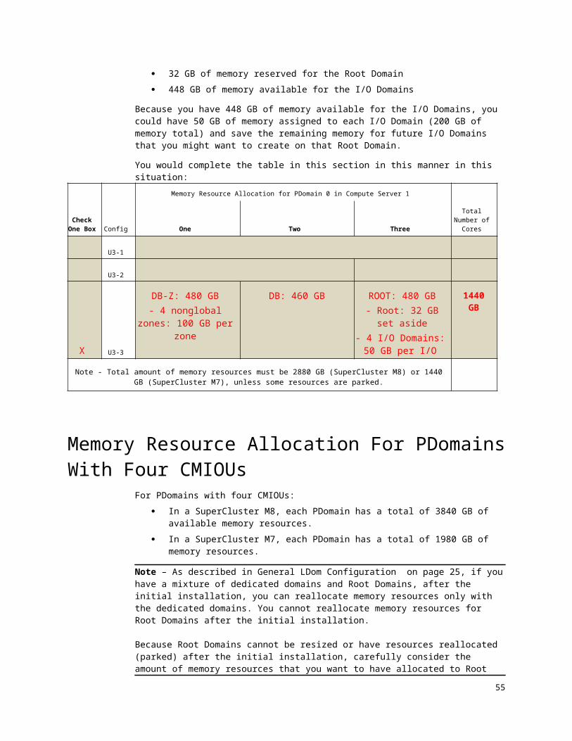
Note – Even though your Oracle installer can configure up to eight database zones or I/O Domains during the initial installation of your Oracle SuperCluster, keep in mind that you can configure additional database zones and I/O Domains after the initial installation. So additional IP addresses might be needed for the management network for these future configurations you set up. Do not provide that information in this table, but keep this in mind so that you can plan accordingly for the total number of IP addresses needed for the management network for the future.
Understanding Client Access Network IP Addresses
As described in Understanding Client Access Network, Network Recipe, VLAN Tag, and RAC Cluster Options on page 47, beginning with the version 2.4 release of the SuperCluster software, you can now have up to eight different client access networks for dedicated domains.
Note – Even though your Oracle installer can configure up to eight database zones or I/O Domains during the initial installation of your Oracle SuperCluster, keep in mind that you can configure additional database zones and I/O Domains after the initial installation. So additional IP addresses might be needed for the 10GbE client access network for these future configurations. Do not provide that information in these tables, but keep this in mind so that you can plan accordingly for the total number of IP addresses needed for the 10GbE client access network for the future.
You need client access network IP addresses for these components in SuperCluster M8 or SuperCluster M7:
One 10GbE client access IP address for certain domains: One 10GbE client access IP address for every dedicated
domain (Database Domain or Application Domain) in each PDomain.
For Root Domains, one 10GbE client access IP address only if the Root Domain is the first LDom in the first PDomain in your SuperCluster M8 or SuperCluster M7.Note that no other Root Domains in your SuperCluster M8 or SuperCluster M7 need a 10GbE client access IP address.
One 10GbE client access IP address for every database zone in a Database Domain that will be set up by your Oracle installer7.
One 10GbE client access IP address for every I/O Domain that will be set up by your Oracle installer7.
Two 10GbE client access IP addresses for the ZFS storage controllers. Note that these IP addresses are automatically pulled from the first (default) client access network.
10GbE client access IP addresses for Oracle RAC VIP and SCAN for every Database Domain (either dedicated domain or Database I/O Domain) and database zone that are part of a RAC:
One Oracle RAC VIP address for each Database Domain (either dedicated domain or Database I/O Domain) that is part of a RAC
One Oracle RAC VIP address for every database zone within a
7 See Oracle Setup of Database Zones and I/O Domains Overview on page 20 for more information. 55

Database Domain (dedicated domain) that is part of a RAC Three SCAN IP addresses for each Oracle RAC in your
SuperCluster M8 or SuperCluster M7 Note that these IP addresses are automatically pulled from the first (default) client access network.
Physical Connections for the Client Access NetworkA 10GbE client access network infrastructure is a required part of the installation process for SuperCluster M8 or SuperCluster M7.
SuperCluster M8 ships with these components:o One quad-port 10 Gb Ethernet Adapter in each CMIOUo Transceivers preinstalled in the 10 Gb Ethernet Adapterso Two 10-meter QFSP+ optical 2-way splitter cables (10m,
MPO/MTP to 2 LC) for each CMIOUFor Root Domains, two 10GbE connections are made to your client network. Optionally, you can request two additional connections. All Root Domains within a PDomain must be cabled the same. This configuration choice must be made during the installation.
SuperCluster M7 ships with these components:o One dual-port Sun Dual 10GbE SFP+ PCIe NIC in each CMIOUo Transceivers preinstalled in the 10GbE NICso One 10-meter SFP-QSFP optical 4-way splitter cable for each
CMIOU
If you plan to use the supplied cables for the connection to your client access network, you must provide these 10GbE client access network infrastructure components:
10GbE switch with available connections, such as the Sun Network 10GbE Switch 72p
Appropriate number of transceivers to connect the splitter cables to your 10GbE switch
If you do not want to use the supplied cables for the connection to your client access network, you must provide these 10GbE client access network infrastructure components:
10GbE switch Suitable optical cables with connections for the compute server side Suitable transceivers to connect all cables to your 10GbE switch
If you do not have a 10GbE client access network infrastructure set up at your site, you must have a 10GbE network switch available at the time of installation that SuperCluster can be connected to, even if the network speed drops from 10 Gb to 1 Gb on the other side of the 10GbE network switch. SuperCluster cannot be installed at the customer site without the 10GbE client access network infrastructure in place.
56 Oracle SuperCluster M8 and SuperCluster M7 Configuration Worksheets • December 2017

Understanding IB Network IP AddressesThis section describes the IB network and the IP addresses that are needed for this network.
Note these important characteristics of the IB network: The IB network is a private network. The IP addresses and host names
assigned to the components and domains for the IB network should not be registered in the DNS.
The IB addresses for the components associated with the Database Domains must be on a different subnet from the IB addresses for the components associated with the Application Domains and Root Domains.
These are the default IB IP addresses for all components in the system that should remain, if possible:
Sequential IP addresses for the first subnet, starting with 192.168.28.1, for the ZFS storage appliance. The ending IP address for this subnet varies, depending on the number of domains and database zones in the system.
Sequential IP addresses for the second subnet, starting with 192.168.10.1, for components associated with the Database Domains. The ending IP address for this subnet varies, depending on the number of Database Domains in the system.
Sequential IP addresses for the third subnet, starting with 192.168.24.1, for the iSCSI devices using IPoIB. The ending IP address for this subnet varies, depending on the number of dedicated domains and Root Domains in the system.
If there are conflicts with the default IP addresses for the IB network and existing IP addresses already on your network, or if this is another SuperCluster system that is being monitored through the same Enterprise Controller host, you can change the default IP addresses. The addresses for the components associated with the Database Domains must remain on a different subnet from the addresses for the components associated with the ZFS storage appliance.
IP Addresses for the ZFS Storage IB Network The default starting IP address for this subnet is 192.168.28.1, and the IP addresses for this subnet are assumed to be sequential.
Note – The instructions in this section assume the starting IP address for this subnet is 192.168.28.1 based on the assumption that this is the only SuperCluster system being monitored by the Enterprise Controller host. If this is not the case, you must use different IP addresses ranges for the IB network for each SuperCluster system. See the list of requirements in IP Addresses and Oracle Enterprise Manager Ops Center 12c Release 2 on page 52 for more information.
You need IP addresses for these components for the ZFS storage IB network: Two IP addresses for the ZFS storage controller cluster One IP address for every dedicated domain (Database Domain or
Application Domain) and Root Domain in each PDomain
57

One IP address for every database zone that is set up by your Oracle installer (see Oracle Setup of Database Zones and I/O Domains Overview on page 20 for more information)
One IP address for every I/O Domain that is set up by your Oracle installer (see Oracle Setup of Database Zones and I/O Domains Overview on page 20 for more information)
Note – Even though your Oracle installer can configure up to eight I/O Domains during the initial installation of your Oracle SuperCluster, keep in mind that you will be able to configure additional I/O Domains after the initial installation. So additional IP addresses might be needed for the IB network for these future configurations you set up. Keep this in mind so that you can plan accordingly for the total number of IP addresses needed for the IB network for the future.
IP Addresses for the Database Domain IB NetworkThe default starting IP address for this subnet is 192.168.10.1, and the IP addresses for this subnet are assumed to be sequential.
Note – The instructions in this section assume the starting IP address for this subnet is 192.168.10.1 based on the assumption that this is the only SuperCluster system being monitored by the Enterprise Controller host. If this is not the case, you must use different IP addresses ranges for the IB network for each SuperCluster system. See the list of requirements in IP Addresses and Oracle Enterprise Manager Ops Center 12c Release 2 on page 52 for more information.
You need IP addresses for the following components on the Database Domain IB network:
Two IP addresses for every storage server in your system Two IP addresses for every Database Domain (dedicated domain) in your
system Two IP addresses for every Database I/O Domain set up by your Oracle
installer8
Two IP addresses for every database zone set up by your Oracle installer8
Note – Even though your Oracle installer can configure up to eight database zones or I/O Domains during the initial installation of your Oracle SuperCluster, keep in mind that you can configure additional database zones and I/O Domains after the initial installation. So additional IP addresses might be needed for the IB network for these future configurations you set up. Keep this in mind so that you can plan accordingly for the total number of IP addresses needed for the IB network for the future.
8 See Oracle Setup of Database Zones and I/O Domains Overview on page 20 for more information.58 Oracle SuperCluster M8 and SuperCluster M7 Configuration Worksheets • December 2017

IP Addresses for the iSCSI Devices Using IPoIB Network The default starting IP address for this subnet is 192.168.24.1, and the IP addresses for this subnet are assumed to be sequential.
Note – The instructions in this section assume the starting IP address for this subnet is 192.168.24.1 based on the assumption that this is the only SuperCluster system being monitored by the Enterprise Controller host. If this is not the case, you must use different IP addresses ranges for the IB network for each SuperCluster system. See the list of requirements in IP Addresses and Oracle Enterprise Manager Ops Center 12c Release 2 on page 52 for more information.
For the iSCSI devices using IPoIB network, you need IP addresses for these components:
Two IP addresses for the ZFS storage controller cluster
Two IP addresses for every domain (either dedicated domains or Root Domains) that you have in your SuperCluster M8 or SuperCluster M7.
Note that you not need additional IP addresses for database zones or I/O Domains for the iSCSI devices using IPoIB network.
For example, assume you have the following configuration: Two compute servers, using the R2-1 PDomain configuration:
Two PDomains in each compute server, for a total of four PDomains in this SuperCluster
Four CMIOUs in each PDomain, or a total of eight CMIOUs in each compute server
U4-3 LDom configuration on each PDomain (three LDoms), with the following types of domains in each U4-3 LDom configuration:
First domain: Database Domain, containing zones, with the Oracle installer setting up four database zones
Second domain: Database Domain, where the Database Domain does not contain zones
Third domain: Root Domain, with the Oracle installer setting up four I/O Domains
In this situation, you would need 26 total IP addresses for the iSCSI devices using IPoIB network:
Two network IP addresses for the ZFS storage controller cluster
Two network IP addresses for each of the three LDoms on each PDomain, with four total PDomains on the two compute servers (2 x 3 x 4).
What’s Next Go to Network Configuration Worksheets on page.
59

Chapter
1Network Configuration Worksheets
Read and understand the information in Determining Network IP Addresses on page 50 before completing any worksheets in this section.
Use the worksheets in this section to provide the starting IP address and to determine the total number of IP addresses that you will need for the networks for your system:
Client Access Network Worksheets on page 61 Management Network Configuration Worksheets on page 63
60 Oracle SuperCluster M8 and SuperCluster M7 Configuration Worksheets • December 2017

Client Access Network Worksheets
Client Access Network -- Physical Connections Worksheet You must provide a 10GbE client access network infrastructure components such as a switch and transceivers for the switch. For further details, refer to these resources:
Physical Connections for the Client Access Network on page 56Resources in other documents: Preparing the Networks Connect SuperCluster Systems to the Facility Networks Compute Server Cables Components
Additionally, for SuperCluster M8, specify how the quad-port 10GbE interfaces are physically configured using this worksheet.
Table 1 – (SuperCluster M8 Only) Client Network Physical Connections Worksheet
Item EntryFor SuperCluster M8:Each quad-port NIC provides four 10 GbE ports through splitter cables. The ports are paired together, providing port pair 1 and port pair 2.By default, port pair 1 is used as the default client access network, and port pair 2 is unused.You can request that port pair 2 be made available as an additional network resource, providing another interface to the same network, or be configured as a different network providing network isolation.
Enable port pair 2? (yes, no)For SuperCluster M8 with port pair 2 enabled:Specify how the additional network interface is configured:
Network 1 – Configure port pair 2 to client access network 1, delivering additional ports and additional bandwidth on the same network.
Network 2 -- Set up as separate isolated network on network 2.
Note to Oracle personnel – Run the appropriate port pairing commands to configure the port pairs.
Client Access Network -- Number of IP Addresses WorksheetsWith the introduction of multiple client access networks in the version 2.4 release of the SuperCluster software, you now provide the necessary information for each client network in Client Access Networks Configuration Worksheets on page 75.
61

As you provide information later in this document on each of the logical domains that you want in your SuperCluster, you also provide information on which of the client access networks you want to use for each of your logical domains.
Use the following table to determine the number of IP addresses that you will need for each client access network, depending on which client access network it is and the type of logical domain.
Table 4 -- Client Access Network IP Addresses Worksheet
Item EntryIf this is the first (default) client access network, default entry of 2 for the 10GbE client access IP addresses for the ZFS storage controllers.
2
If the first LDom in the first PDomain is a Root Domain, enter 1 in this field. Do not provide entries for any other Root Domain in your SuperCluster.For compute server 1, enter the number of dedicated domains, I/O Domains and database zones that the Oracle installer will configure on this server, so that one 10GbE client access IP address is assigned to each of these domains and zones. Do not include any Root Domains in this entry.
For compute server 2, enter the number of dedicated domains, I/O Domains and database zones that the Oracle installer will configure on this server, so that one 10GbE client access IP address is assigned to each of these domains and zones. Do not include any Root Domains in this entry.
For compute server 1, how many of the following are part of a RAC: Database Domains (dedicated domains or Database I/O
Domains) Database zones
Enter the total number of Database Domains and database zones on this server that are part of a RAC, so that one RAC VIP address is assigned to each Database Domain and database zone in the server.
For compute server 2, how many of the following are part of a RAC: Database Domains (dedicated domains or Database I/O
Domains) Database zones
Enter the total number of Database Domains and database zones on this server that are part of a RAC, so that one RAC VIP address is assigned to each Database Domain and database zone in the server.
How many Oracle RACs will there be altogether within your SuperCluster M8 or SuperCluster M7?Enter the total number of Oracle RACs that will be in your system times 3 so that three SCAN IP addresses are assigned
62 Oracle SuperCluster M8 and SuperCluster M7 Configuration Worksheets • December 2017

to each RAC. For example, if you have four Oracle RACs in your system, enter 12 in this field.Add the entries from the Entry column. This is the total number of IP addresses that you will need for the client access network for this server.
What’s Next Go to Management Network Configuration Worksheets on page 63 to provide network parameters for the IB network.
Management Network Configuration Worksheets
Complete the worksheets in the following sections for the management network: General Management Network Configuration Worksheet on page 63 Management Network IP Addresses Configuration Worksheet on page 65
General Management Network Configuration WorksheetUse this worksheet to provide the subnet mask and gateway IP address for the management network.
Table 5 -- General Management Network Configuration Worksheet
Item Entry Description and Example
Management network starting IP address
Starting IP address for the management network.Example: 10.204.74.100
Management network gateway IP address
Gateway IP address for the management network.Example: 10.204.74.1
Management network subnet mask
Subnet mask for the management network.Example: 255.255.255.0
Use management network gateway for default gateway?
For the default gateway, you can use either the management network gateway or the client access network gateway. Options for this field: Yes if the management network
63

gateway will be the default gateway No if the management network
gateway will not be the default gateway (if the client access network gateway will be the default gateway)
64 Oracle SuperCluster M8 and SuperCluster M7 Configuration Worksheets • December 2017

Management Network IP Addresses Configuration WorksheetComplete this worksheet to determine the total number of IP addresses needed for the management network. These IP addresses should be sequential, beginning with the starting IP address that you provided in General ManagementNetwork Configuration Worksheet on page 63.
Table 6 -- Management Network IP Addresses Configuration Worksheet
Item EntryDefault entry of 12 for the 1GbE host management and Oracle ILOM IP addresses for the switches, PDUs, and ZFS storage controllers.
12
Enter the number of compute servers in your SuperCluster M8 or SuperCluster M7 (1 or 2) for the 1GbE host management IP addresses for the floating service processors in each compute server. For every storage server in your SuperCluster M8 or SuperCluster M7, enter the number of storage servers times 2 for the 1GbE host management and Oracle ILOM IP addresses for each storage server. For every PDomain in your SuperCluster M8 or SuperCluster M7, enter the number of PDomains times 2 (IP addresses for the service processors in each server).For compute server 1, how many domains (dedicated domains, Root Domains and I/O Domains) and database zones will the Oracle installer configure on this server?Enter the total number of domains and database zones on this server. For compute server 2, how many domains (dedicated domains, Root Domains and I/O Domains) and database zones will the Oracle installer configure on this server?Enter the total number of domains and database zones on this server. Add the entries from the Entry column. This is the total number of IP addresses that you need for the management network.
What’s Next Go to IB Network IP Addresses Configuration Worksheets on page 66.
65

IB Network IP Addresses Configuration Worksheets
Complete the worksheets in this section for the IB network.
General IB Network Configuration WorksheetUse this worksheet to provide the subnet mask and gateway IP address for the IB network.
Table 7 -- General IB Network Configuration Worksheet
Item Entry Description and Example
IB network subnet mask
255.255.252.0 Subnet mask for the IB network. Only valid entry for this field: 255.255.252.0
66 Oracle SuperCluster M8 and SuperCluster M7 Configuration Worksheets • December 2017

IP Addresses for the ZFS Storage IB Network Configuration WorksheetsThe default starting IP address for this subnet is 192.168.28.1, and the IP addresses for this subnet are assumed to be sequential.
Table 8 -- IP Addresses for the ZFS Storage IB Network Configuration Worksheets
Item EntryDefault entry of 2 for the IB IP addresses for the ZFS storage controller cluster.
2
Enter the number of dedicated domains (Database Domain or Application Domain) and Root Domains in each PDomain.Enter the number of I/O Domains and database zones that will be set up by your Oracle installer at the time of the initial installation.Add the entries from the Entry column. This is the total number of IP addresses that you will need for the ZFS storage IB network.
If there are conflicts on your network with sequential IP addresses starting with 192.168.28.1 for this subnet, enter an alternate starting IP address for this subnet in the table below. Note that you can choose a different subnet from 192.168.28.1, if necessary, as long as it is not the same subnet as the one used in the section IP Addresses for the Database Domain IB Network Configuration Worksheets on page 68.
Item EntryEnter the alternate starting IP address.If necessary, enter the alternate subnet for the IB network for this subnet.
67

IP Addresses for the Database Domain IB Network Configuration WorksheetsThe default starting IP address for this subnet is 192.168.10.1, and the IP addresses for this subnet are assumed to be sequential.
Table 9 -- IP Addresses for the Database Domain IB Network Configuration Worksheets
Item EntryFor every storage server in your SuperCluster M8 or SuperCluster M7, enter the number of storage servers times 2. For example, if you have three storage servers in your system, enter 6 here.For compute server 1, enter the number of Database Domains (dedicated domains or Database I/O Domains) and database zones on this server times 2. For example, if you have two Database Domains (dedicated domains or Database I/O Domains) and four database zones in your system, enter 12 here. For compute server 2, enter the number of Database Domains (dedicated domains or Database I/O Domains) and database zones on this server times 2. For example, if you have two Database Domains (dedicated domains or Database I/O Domains) and four database zones in your system, enter 12 here.Add the entries from the Entry column. This is the total number of IP addresses that you need for the Database Domain IB network.
If there are conflicts on your network with sequential IP addresses starting with 192.168.10.1 for this subnet, enter an alternate starting IP address for this subnet in the table below. Note that you can choose a different subnet from 192.168.10.1, if necessary, as long as it is not the same subnet used in the section IP Addresses for the ZFS Storage IB Network Configuration Worksheets on page 67.
Item EntryEnter the alternate starting IP address.If necessary, enter the alternate subnet for the IB network for this subnet.
68 Oracle SuperCluster M8 and SuperCluster M7 Configuration Worksheets • December 2017

IP Addresses for the iSCSI Devices Using IPoIB Network Configuration WorksheetsThe default starting IP address for this subnet is 192.168.24.1, and the IP addresses for this subnet are assumed to be sequential.
Complete this worksheet to determine the total number of IP addresses needed for the iSCSI devices using IPoIB network. Provide the information only for the number of PDomains that you have in your SuperCluster M8 or SuperCluster M7. In other words, if you have two total PDomains in your SuperCluster M8 or SuperCluster M7, provide the information only for the first two PDomains and ignore the questions for the third and fourth PDomains.
Table 10 -- IP Addresses for the iSCSI Devices Using IPoIB Network Configuration Worksheets
Item EntryFor the first PDomain in your SuperCluster M8 or SuperCluster M7, enter the number of LDoms that are part of this PDomain (1-4 LDoms).For the second PDomain in your SuperCluster M8 or SuperCluster M7, enter the number of LDoms that are part of this PDomain (1-4 LDoms).If applicable, for the third PDomain in your SuperCluster M8 or SuperCluster M7, enter the number of LDoms that are part of this PDomain (1-4 LDoms). If applicable, for the fourth PDomain in your SuperCluster M8 or SuperCluster M7, enter the number of LDoms that are part of this PDomain (1-4 LDoms).Add the entries from the Entry column. This is the total number of LDoms that you have in your SuperCluster M8 or SuperCluster M7.Multiply the total number of LDoms in your SuperCluster M8 or SuperCluster M7 by 2. This is the total number of IP addresses that you need for the LDoms for the iSCSI devices using IPoIB network.Default entry of 2 for the IP addresses for the ZFS storage controller cluster.
2
Add these two entries together (LDom IP addresses entry and ZFS storage controller cluster entry). This is the total number of IP addresses that you need for the iSCSI devices using IPoIB network.
What’s Next Go to Rack Configuration Worksheets on page 52 to provide general rack configuration information.
69

70 Oracle SuperCluster M8 and SuperCluster M7 Configuration Worksheets • December 2017

Chapter
1Rack Configuration Worksheets
Read and understand the information in Understanding Client Access Network, Network Recipe, VLAN Tag, and RAC Cluster Options on page 47 before completing the worksheets in this chapter.
General Rack Configuration Worksheets
Table 11: General Rack Configuration Worksheets
Item Entry Description and Example
Number of Client Networks
Determine how many client networks are needed for the entire SuperCluster M8 or SuperCluster M7. Options: 1 – 8 Minimum is 1. Optionally, for dedicated domains, you can specify 2 through 8.
NOTE: Provide the number of client networks in this table, and provide the actual client network information in Client Access Networks Configuration Worksheets on page 75.
71

Item Entry Description and Example
Number of Network Recipes
Determine how many network recipes are needed for the entire SuperCluster M8 or SuperCluster M7. Options: 1 – 8 NOTE: Provide the number of network recipes in this table, and provide the actual network recipe information in Network Recipe Configuration Worksheets on page 80.
Number of VLAN Tags
Determine how many VLAN tags are needed for the entire SuperCluster M8 or SuperCluster M7. Options: 1 – 16 NOTE: Provide the number of VLAN tags in this table, and provide the actual VLAN tags in VLAN Tag Configuration Worksheets on page 86.
Use Client Hostnames
Every Oracle Solaris domain on SuperCluster M8 or SuperCluster M7 has a host name. By default, the host name given is the same name associated with the management network interface. But the host name can also be the set to the name associated with the 10GbE client network interface. Determine if you want to use the client interface host name as the host name for all Oracle Solaris domains. For example, you may choose to use the client interface host names if your applications require that the host name match the interface over which the clients connect. Choose Yes if you want to have the client
interface host name as the host name for all Oracle Solaris domains.
Choose No if you want the default management host name as the host name for all Oracle Solaris domains.
Options: Yes or NoDefault option is No.
Number Clusters for Oracle Database
Enter the type and total number of: RAC Clusters Clusterware instances Grid Infrastructures
NOTE: Provide the number of RAC Clusters in this table, and provide the actual cluster details in RAC Cluster Configuration Worksheets on page 88.
Number of InfiniBand
Two IB leaf switches and one IB spine switch is typically included in SuperCluster
72 Oracle SuperCluster M8 and SuperCluster M7 Configuration Worksheets • December 2017

Item Entry Description and Example
Switches M8 or SuperCluster M7. However, some configurations of the system do not include the IB spine switch.Options: 2 or 3 Choose 2 if your SuperCluster does not
include the IB spine switch Choose 3 if your SuperCluster has the
two IB leaf switches and the IB spine switch
Number of Exadata Storage Servers
The number of storage servers that you have in your SuperCluster M8 or SuperCluster M7.Options: 3 – 11 storage servers if you have one
compute server in your SuperCluster M8 or SuperCluster M7
3 – 6 storage servers if you have two compute servers in your SuperCluster M8 or SuperCluster M7
Hostname Prefix
The prefix is used to generate host names for network interfaces for components in the system. For example, a value of sc01 results in a compute node host name of sc01db01, and a storage server host name of sc01cel01. Because this is used to generate host names for network interfaces for components in the system, Use a name of fewer than six characters for the prefix.Example: sc01
Exadata Storage Server Type
The type of storage servers that you have in your SuperCluster M8 or SuperCluster M7.Options: Extreme Flash High Capacity
Note to Oracle installers – Information on the starting IP addresses for the management and IB networks can be found in Network Configuration Worksheets on page 60.
What’s Next Go to Client Access Networks Configuration Worksheets on page 75 to provide starting IP addresses and IP address ranges for the three networks for your system.
73

74 Oracle SuperCluster M8 and SuperCluster M7 Configuration Worksheets • December 2017

Chapter
1Client Access Networks Configuration
WorksheetsComplete the worksheets in this chapter to provide the necessary information for each of the client access networks that you want to use for your SuperCluster:
Client Network 01 (Default Client Network)Complete these worksheets for additional networks for dedicated domains: Client Network 02 on page 76 Client Network 03 on page 77 Client Network 04 on page 77 Client Network 05 on page 77 Client Network 06 on page 78 Client Network 07 on page 78 Client Network 08 on page 79
Client Network 01 (Default Client Network)Table 12 -- Client Network 01 (Default Client Network)
Item Entry Description and Example
Start IP Starting IP address for this client access network.
Gateway Gateway IP address for this client access network.
75

Item Entry Description and Example
Netmask Subnet mask for this client access network.
Table 13 – Optional Second Client Network for Root Domains
Only complete this table if you selected to configure a second port pair for SuperCluster M8 Root Domains, and you want the second port pair to connect to a different network endpoint. See Client Access Network -- Physical Connections Worksheet on page 61.
Item Entry Description and Example
Start IP Starting IP address for this client access network.
Gateway Gateway IP address for this client access network.
Netmask Subnet mask for this client access network.
Client Network 02Note – Only specify additional client networks if you want additional networks for dedicated domains.
Table 14 -- Client Network 02
Item Entry Description and Example
Start IP Starting IP address for this client access network.
Gateway Gateway IP address for this client access network.
Netmask Subnet mask for this client access network.
76 Oracle SuperCluster M8 and SuperCluster M7 Configuration Worksheets • December 2017

Client Network 03Note – Only specify additional client networks if you want additional networks for dedicated domains.
Table 15 -- Client Network 03
Item Entry Description and Example
Start IP Starting IP address for this client access network.
Gateway Gateway IP address for this client access network.
Netmask Subnet mask for this client access network.
Client Network 04Note – Only specify additional client networks if you want additional networks for dedicated domains.
Table 16 -- Client Network 04
Item Entry Description and Example
Start IP Starting IP address for this client access network.
Gateway Gateway IP address for this client access network.
Netmask Subnet mask for this client access network.
Client Network 05Note – Only specify additional client networks if you want additional networks for dedicated domains.
77

Table 17 -- Client Network 05
Item Entry Description and Example
Start IP Starting IP address for this client access network.
Gateway Gateway IP address for this client access network.
Netmask Subnet mask for this client access network.
Client Network 06Note – Only specify additional client networks if you want additional networks for dedicated domains.
Table 18 -- Client Network 06
Item Entry Description and Example
Start IP Starting IP address for this client access network.
Gateway Gateway IP address for this client access network.
Netmask Subnet mask for this client access network.
Client Network 07Note – Only specify additional client networks if you want additional networks for dedicated domains.
Table 19 -- Client Network 07
Item Entry Description and Example
Start IP Starting IP address for this client access network.
78 Oracle SuperCluster M8 and SuperCluster M7 Configuration Worksheets • December 2017

Item Entry Description and Example
Gateway Gateway IP address for this client access network.
Netmask Subnet mask for this client access network.
Client Network 08Note – Only specify additional client networks if you want additional networks for dedicated domains.
Table 20 -- Client Network 08
Item Entry Description and Example
Start IP Starting IP address for this client access network.
Gateway Gateway IP address for this client access network.
Netmask Subnet mask for this client access network.
What’s Next Go to Network Recipe Configuration Worksheets on page 80.
79

Chapter
1Network Recipe Configuration
WorksheetsComplete the worksheets in this chapter to provide the necessary information for each of the network recipes that you want to use for your SuperCluster:
Network Recipe 01 (Default Client Network) on page 80 Network Recipe 02 on page 81 Network Recipe 03 on page 81 Network Recipe 04 on page 82 Network Recipe 05 on page 83 Network Recipe 06 on page 83 Network Recipe 07 on page 84 Network Recipe 08 on page 84
Network Recipe 01 (Default Client Network)Table 21 -- Network Recipe 01
Item Entry Description and Example
Recipe Name Name for this particular network recipe.Example: los_angeles
Domain Name Domain name for this particular network recipe.Example: example.com
Name Servers IP addresses of the name servers for this network recipe, separated by spaces. Example: 192.0.2.1 192.0.2.2
80 Oracle SuperCluster M8 and SuperCluster M7 Configuration Worksheets • December 2017

Item Entry Description and Example
Time Servers IP addresses of the time servers for this network recipe, separated by spaces. Example: 192.0.2.14 192.0.2.15
Time zone Time zone for this network recipe. Example: America/Los_Angeles
Network Recipe 02Table 22 -- Network Recipe 02
Item Entry Description
Recipe Name Name for this particular network recipe.
Domain Name Domain name for this particular network recipe.
Name Servers IP addresses of the name servers for this network recipe, separated by spaces.
Time Servers IP addresses of the time servers for this network recipe, separated by spaces.
Time zone Time zone for this network recipe.
Network Recipe 03Table 23 -- Network Recipe 03
Item Entry Description
Recipe Name Name for this particular network recipe.
Domain Name Domain name for this particular network recipe.
81

Item Entry Description
Name Servers IP addresses of the name servers for this network recipe, separated by spaces.
Time Servers IP addresses of the time servers for this network recipe, separated by spaces.
Time zone Time zone for this network recipe.
Network Recipe 04Table 24 -- Network Recipe 04
Item Entry Description
Recipe Name Name for this particular network recipe.
Domain Name Domain name for this particular network recipe.
Name Servers IP addresses of the name servers for this network recipe, separated by spaces.
Time Servers IP addresses of the time servers for this network recipe, separated by spaces.
Time zone Time zone for this network recipe.
82 Oracle SuperCluster M8 and SuperCluster M7 Configuration Worksheets • December 2017

Network Recipe 05Table 25 -- Network Recipe 05
Item Entry Description
Recipe Name Name for this particular network recipe.
Domain Name Domain name for this particular network recipe.
Name Servers IP addresses of the name servers for this network recipe, separated by spaces.
Time Servers IP addresses of the time servers for this network recipe, separated by spaces.
Time zone Time zone for this network recipe.
Network Recipe 06Table 26 -- Network Recipe 06
Item Entry Description
Recipe Name Name for this particular network recipe.
Domain Name Domain name for this particular network recipe.
Name Servers IP addresses of the name servers for this network recipe, separated by spaces.
Time Servers IP addresses of the time servers for this network recipe, separated by spaces.
Time zone Time zone for this network recipe.
83

Network Recipe 07Table 27 -- Network Recipe 07
Item Entry Description
Recipe Name Name for this particular network recipe.
Domain Name Domain name for this particular network recipe.
Name Servers IP addresses of the name servers for this network recipe, separated by spaces.
Time Servers IP addresses of the time servers for this network recipe, separated by spaces.
Time zone Time zone for this network recipe.
Network Recipe 08Table 28 -- Network Recipe 08
Item Entry Description
Recipe Name Name for this particular network recipe.
Domain Name Domain name for this particular network recipe.
Name Servers IP addresses of the name servers for this network recipe, separated by spaces.
Time Servers IP addresses of the time servers for this network recipe, separated by spaces.
84 Oracle SuperCluster M8 and SuperCluster M7 Configuration Worksheets • December 2017

Item Entry Description
Time zone Time zone for this network recipe.
What’s Next Go to VLAN Tag Configuration Worksheets on page 86.
85

Chapter
1VLAN Tag Configuration Worksheets
Complete the worksheets in this chapter to provide the necessary information for the VLAN tags that you want to use for your SuperCluster, if necessary.
Table 29 -- VLAN Tag Configuration Worksheet
Item Entry Description and Example
VLAN Tag 01 This VLAN tag ID. Example: 101
VLAN Tag 02 This VLAN tag ID. Example: 102
VLAN Tag 03 This VLAN tag ID. Example: 103
VLAN Tag 04 This VLAN tag ID. Example: 104
VLAN Tag 05 This VLAN tag ID. Example: 105
VLAN Tag 06 This VLAN tag ID. Example: 106
VLAN Tag 07 This VLAN tag ID. Example: 107
VLAN Tag 08 This VLAN tag ID. Example: 108
86 Oracle SuperCluster M8 and SuperCluster M7 Configuration Worksheets • December 2017

Item Entry Description and Example
VLAN Tag 09 This VLAN tag ID. Example: 109
VLAN Tag 10 This VLAN tag ID. Example: 110
VLAN Tag 11 This VLAN tag ID. Example: 111
VLAN Tag 12 This VLAN tag ID. Example: 112
VLAN Tag 13 This VLAN tag ID. Example: 113
VLAN Tag 14 This VLAN tag ID. Example: 114
VLAN Tag 15 This VLAN tag ID. Example: 115
VLAN Tag 16 This VLAN tag ID. Example: 116
What’s Next Go to RAC Cluster Configuration Worksheets on page 88.
87

Chapter
1RAC Cluster Configuration
WorksheetsComplete the worksheets in this chapter to provide the necessary information for each of the RAC Clusters that you want to use for your SuperCluster:
RAC Cluster Worksheets (Clusters 1 – 10) on page 88 RAC Cluster Worksheets (Clusters 11 – 20) on page 95 RAC Cluster Worksheets (Clusters 21 – 32) on page 101
RAC Cluster Worksheets (Clusters 1 – 10)
Table 30 -- RAC Cluster 1
Item Entry Description and Example
Client Network The client network that you want to use for this cluster. See the information that you provided in Client Access Networks Configuration Worksheets on page 75 for more information on the available client networks.Example: Client network 1
Network Recipe The network recipe that you want to use for this cluster. See the information that you provided in Network Recipe Configuration Worksheets on page 80 for more information on the available network recipes.Example: Network recipe 1
88 Oracle SuperCluster M8 and SuperCluster M7 Configuration Worksheets • December 2017

Item Entry Description and Example
VLAN The VLAN tag that you want to use for this cluster, if necessary. See VLAN Tag Configuration Worksheets on page 86 for more information on the available VLAN tags.Example: 101
Table 31 -- RAC Cluster 2
Item Entry Description and Example
Client Network The client network that you want to use for this cluster. See the information that you provided in Client Access Networks Configuration Worksheets on page 75 for more information on the available client networks.Example: Client network 1
Network Recipe The network recipe that you want to use for this cluster. See the information that you provided in Network Recipe Configuration Worksheets on page 80 for more information on the available network recipes.Example: Network recipe 1
VLAN The VLAN tag that you want to use for this cluster, if necessary. See VLAN Tag Configuration Worksheets on page 86 for more information on the available VLAN tags.Example: 101
Table 32 -- RAC Cluster 3
Item Entry Description and Example
Client Network The client network that you want to use for this cluster. See the information that you provided in Client Access Networks Configuration Worksheets on page 75 for more information on the available client networks.Example: Client network 1
89
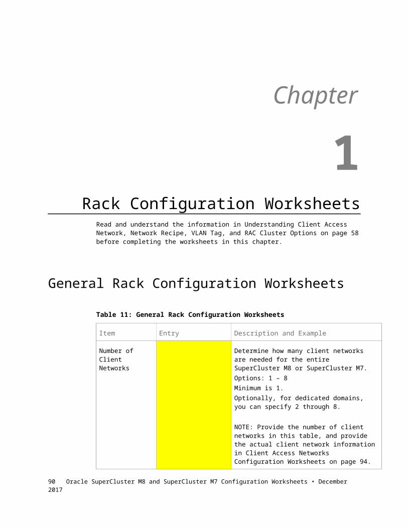
Item Entry Description and Example
Network Recipe The network recipe that you want to use for this cluster. See the information that you provided in Network Recipe Configuration Worksheets on page 80 for more information on the available network recipes.Example: Network recipe 1
VLAN The VLAN tag that you want to use for this cluster, if necessary. See VLAN Tag Configuration Worksheets on page 86 for more information on the available VLAN tags.Example: 101
Table 33 -- RAC Cluster 4
Item Entry Description and Example
Client Network The client network that you want to use for this cluster. See the information that you provided in Client Access Networks Configuration Worksheets on page 75 for more information on the available client networks.Example: Client network 1
Network Recipe The network recipe that you want to use for this cluster. See the information that you provided in Network Recipe Configuration Worksheets on page 80 for more information on the available network recipes.Example: Network recipe 1
VLAN The VLAN tag that you want to use for this cluster, if necessary. See VLAN Tag Configuration Worksheets on page 86 for more information on the available VLAN tags.Example: 101
90 Oracle SuperCluster M8 and SuperCluster M7 Configuration Worksheets • December 2017

Table 34 -- RAC Cluster 5
Item Entry Description and Example
Client Network The client network that you want to use for this cluster. See the information that you provided in Client Access Networks Configuration Worksheets on page 75 for more information on the available client networks.Example: Client network 1
Network Recipe The network recipe that you want to use for this cluster. See the information that you provided in Network Recipe Configuration Worksheets on page 80 for more information on the available network recipes.Example: Network recipe 1
VLAN The VLAN tag that you want to use for this cluster, if necessary. See VLAN Tag Configuration Worksheets on page 86 for more information on the available VLAN tags.Example: 101
Table 35 -- RAC Cluster 6
Item Entry Description and Example
Client Network The client network that you want to use for this cluster. See the information that you provided in Client Access Networks Configuration Worksheets on page 75 for more information on the available client networks.Example: Client network 1
Network Recipe The network recipe that you want to use for this cluster. See the information that you provided in Network Recipe Configuration Worksheets on page 80 for more information on the available network recipes.Example: Network recipe 1
VLAN The VLAN tag that you want to use for this cluster, if necessary. See VLAN Tag Configuration Worksheets on page 86 for more information on the available VLAN tags.Example: 101
91

Table 36 -- RAC Cluster 7
Item Entry Description and Example
Client Network The client network that you want to use for this cluster. See the information that you provided in Client Access Networks Configuration Worksheets on page 75 for more information on the available client networks.Example: Client network 1
Network Recipe The network recipe that you want to use for this cluster. See the information that you provided in Network Recipe Configuration Worksheets on page 80 for more information on the available network recipes.Example: Network recipe 1
VLAN The VLAN tag that you want to use for this cluster, if necessary. See VLAN Tag Configuration Worksheets on page 86 for more information on the available VLAN tags.Example: 101
Table 37 -- RAC Cluster 8
Item Entry Description and Example
Client Network The client network that you want to use for this cluster. See the information that you provided in Client Access Networks Configuration Worksheets on page 75 for more information on the available client networks.Example: Client network 1
Network Recipe The network recipe that you want to use for this cluster. See the information that you provided in Network Recipe Configuration Worksheets on page 80 for more information on the available network recipes.Example: Network recipe 1
VLAN The VLAN tag that you want to use for this cluster, if necessary. See VLAN Tag Configuration Worksheets on page 86 for more information on the available VLAN tags.Example: 101
92 Oracle SuperCluster M8 and SuperCluster M7 Configuration Worksheets • December 2017

Table 38 -- RAC Cluster 9
Item Entry Description and Example
Client Network The client network that you want to use for this cluster. See the information that you provided in Client Access Networks Configuration Worksheets on page 75 for more information on the available client networks.Example: Client network 1
Network Recipe The network recipe that you want to use for this cluster. See the information that you provided in Network Recipe Configuration Worksheets on page 80 for more information on the available network recipes.Example: Network recipe 1
VLAN The VLAN tag that you want to use for this cluster, if necessary. See VLAN Tag Configuration Worksheets on page 86 for more information on the available VLAN tags.Example: 101
Table 39 -- RAC Cluster 10
Item Entry Description and Example
Client Network The client network that you want to use for this cluster. See the information that you provided in Client Access Networks Configuration Worksheets on page 75 for more information on the available client networks.Example: Client network 1
Network Recipe The network recipe that you want to use for this cluster. See the information that you provided in Network Recipe Configuration Worksheets on page 80 for more information on the available network recipes.Example: Network recipe 1
VLAN The VLAN tag that you want to use for this cluster, if necessary. See VLAN Tag Configuration Worksheets on page 86 for more information on the available VLAN tags.Example: 101
93

94 Oracle SuperCluster M8 and SuperCluster M7 Configuration Worksheets • December 2017

RAC Cluster Worksheets (Clusters 11 – 20)
Table 40 -- RAC Cluster 11
Item Entry Description and Example
Client Network The client network that you want to use for this cluster. See the information that you provided in Client Access Networks Configuration Worksheets on page 75 for more information on the available client networks.Example: Client network 1
Network Recipe The network recipe that you want to use for this cluster. See the information that you provided in Network Recipe Configuration Worksheets on page 80 for more information on the available network recipes.Example: Network recipe 1
VLAN The VLAN tag that you want to use for this cluster, if necessary. See VLAN Tag Configuration Worksheets on page 86 for more information on the available VLAN tags.Example: 101
Table 41 -- RAC Cluster 12
Item Entry Description and Example
Client Network The client network that you want to use for this cluster. See the information that you provided in Client Access Networks Configuration Worksheets on page 75 for more information on the available client networks.Example: Client network 1
Network Recipe The network recipe that you want to use for this cluster. See the information that you provided in Network Recipe Configuration Worksheets on page 80 for more information on the available network recipes.Example: Network recipe 1
95

Item Entry Description and Example
VLAN The VLAN tag that you want to use for this cluster, if necessary. See VLAN Tag Configuration Worksheets on page 86 for more information on the available VLAN tags.Example: 101
Table 42 -- RAC Cluster 13
Item Entry Description and Example
Client Network The client network that you want to use for this cluster. See the information that you provided in Client Access Networks Configuration Worksheets on page 75 for more information on the available client networks.Example: Client network 1
Network Recipe The network recipe that you want to use for this cluster. See the information that you provided in Network Recipe Configuration Worksheets on page 80 for more information on the available network recipes.Example: Network recipe 1
VLAN The VLAN tag that you want to use for this cluster, if necessary. See VLAN Tag Configuration Worksheets on page 86 for more information on the available VLAN tags.Example: 101
Table 43 -- RAC Cluster 14
Item Entry Description and Example
Client Network The client network that you want to use for this cluster. See the information that you provided in Client Access Networks Configuration Worksheets on page 75 for more information on the available client networks.Example: Client network 1
96 Oracle SuperCluster M8 and SuperCluster M7 Configuration Worksheets • December 2017

Item Entry Description and Example
Network Recipe The network recipe that you want to use for this cluster. See the information that you provided in Network Recipe Configuration Worksheets on page 80 for more information on the available network recipes.Example: Network recipe 1
VLAN The VLAN tag that you want to use for this cluster, if necessary. See VLAN Tag Configuration Worksheets on page 86 for more information on the available VLAN tags.Example: 101
Table 44 -- RAC Cluster 15
Item Entry Description and Example
Client Network The client network that you want to use for this cluster. See the information that you provided in Client Access Networks Configuration Worksheets on page 75 for more information on the available client networks.Example: Client network 1
Network Recipe The network recipe that you want to use for this cluster. See the information that you provided in Network Recipe Configuration Worksheets on page 80 for more information on the available network recipes.Example: Network recipe 1
VLAN The VLAN tag that you want to use for this cluster, if necessary. See VLAN Tag Configuration Worksheets on page 86 for more information on the available VLAN tags.Example: 101
97

Table 45 --RAC Cluster 16
Item Entry Description and Example
Client Network The client network that you want to use for this cluster. See the information that you provided in Client Access Networks Configuration Worksheets on page 75 for more information on the available client networks.Example: Client network 1
Network Recipe The network recipe that you want to use for this cluster. See the information that you provided in Network Recipe Configuration Worksheets on page 80 for more information on the available network recipes.Example: Network recipe 1
VLAN The VLAN tag that you want to use for this cluster, if necessary. See VLAN Tag Configuration Worksheets on page 86 for more information on the available VLAN tags.Example: 101
Table 46 -- RAC Cluster 17
Item Entry Description and Example
Client Network The client network that you want to use for this cluster. See the information that you provided in Client Access Networks Configuration Worksheets on page 75 for more information on the available client networks.Example: Client network 1
Network Recipe The network recipe that you want to use for this cluster. See the information that you provided in Network Recipe Configuration Worksheets on page 80 for more information on the available network recipes.Example: Network recipe 1
VLAN The VLAN tag that you want to use for this cluster, if necessary. See VLAN Tag Configuration Worksheets on page 86 for more information on the available VLAN tags.Example: 101
98 Oracle SuperCluster M8 and SuperCluster M7 Configuration Worksheets • December 2017

Table 47 -- RAC Cluster 18
Item Entry Description and Example
Client Network The client network that you want to use for this cluster. See the information that you provided in Client Access Networks Configuration Worksheets on page 75 for more information on the available client networks.Example: Client network 1
Network Recipe The network recipe that you want to use for this cluster. See the information that you provided in Network Recipe Configuration Worksheets on page 80 for more information on the available network recipes.Example: Network recipe 1
VLAN The VLAN tag that you want to use for this cluster, if necessary. See VLAN Tag Configuration Worksheets on page 86 for more information on the available VLAN tags.Example: 101
Table 48 -- RAC Cluster 19
Item Entry Description and Example
Client Network The client network that you want to use for this cluster. See the information that you provided in Client Access Networks Configuration Worksheets on page 75 for more information on the available client networks.Example: Client network 1
Network Recipe The network recipe that you want to use for this cluster. See the information that you provided in Network Recipe Configuration Worksheets on page 80 for more information on the available network recipes.Example: Network recipe 1
VLAN The VLAN tag that you want to use for this cluster, if necessary. See VLAN Tag Configuration Worksheets on page 86 for more information on the available VLAN tags.Example: 101
99

Table 49 -- RAC Cluster 20
Item Entry Description and Example
Client Network The client network that you want to use for this cluster. See the information that you provided in Client Access Networks Configuration Worksheets on page 75 for more information on the available client networks.Example: Client network 1
Network Recipe The network recipe that you want to use for this cluster. See the information that you provided in Network Recipe Configuration Worksheets on page 80 for more information on the available network recipes.Example: Network recipe 1
VLAN The VLAN tag that you want to use for this cluster, if necessary. See VLAN Tag Configuration Worksheets on page 86 for more information on the available VLAN tags.Example: 101
100 Oracle SuperCluster M8 and SuperCluster M7 Configuration Worksheets • December 2017

RAC Cluster Worksheets (Clusters 21 – 32)
Table 50 -- RAC Cluster 21
Item Entry Description and Example
Client Network The client network that you want to use for this cluster. See the information that you provided in Client Access Networks Configuration Worksheets on page 75 for more information on the available client networks.Example: Client network 1
Network Recipe The network recipe that you want to use for this cluster. See the information that you provided in Network Recipe Configuration Worksheets on page 80 for more information on the available network recipes.Example: Network recipe 1
VLAN The VLAN tag that you want to use for this cluster, if necessary. See VLAN Tag Configuration Worksheets on page 86 for more information on the available VLAN tags.Example: 101
Table 51 -- RAC Cluster 22
Item Entry Description and Example
Client Network The client network that you want to use for this cluster. See the information that you provided in Client Access Networks Configuration Worksheets on page 75 for more information on the available client networks.Example: Client network 1
Network Recipe The network recipe that you want to use for this cluster. See the information that you provided in Network Recipe Configuration Worksheets on page 80 for more information on the available network recipes.Example: Network recipe 1
101

Item Entry Description and Example
VLAN The VLAN tag that you want to use for this cluster, if necessary. See VLAN Tag Configuration Worksheets on page 86 for more information on the available VLAN tags.Example: 101
Table 52 -- RAC Cluster 23
Item Entry Description and Example
Client Network The client network that you want to use for this cluster. See the information that you provided in Client Access Networks Configuration Worksheets on page 75 for more information on the available client networks.Example: Client network 1
Network Recipe The network recipe that you want to use for this cluster. See the information that you provided in Network Recipe Configuration Worksheets on page 80 for more information on the available network recipes.Example: Network recipe 1
VLAN The VLAN tag that you want to use for this cluster, if necessary. See VLAN Tag Configuration Worksheets on page 86 for more information on the available VLAN tags.Example: 101
Table 53 -- RAC Cluster 24
Item Entry Description and Example
Client Network The client network that you want to use for this cluster. See the information that you provided in Client Access Networks Configuration Worksheets on page 75 for more information on the available client networks.Example: Client network 1
102 Oracle SuperCluster M8 and SuperCluster M7 Configuration Worksheets • December 2017

Item Entry Description and Example
Network Recipe The network recipe that you want to use for this cluster. See the information that you provided in Network Recipe Configuration Worksheets on page 80 for more information on the available network recipes.Example: Network recipe 1
VLAN The VLAN tag that you want to use for this cluster, if necessary. See VLAN Tag Configuration Worksheets on page 86 for more information on the available VLAN tags.Example: 101
Table 54 -- RAC Cluster 25
Item Entry Description and Example
Client Network The client network that you want to use for this cluster. See the information that you provided in Client Access Networks Configuration Worksheets on page 75 for more information on the available client networks.Example: Client network 1
Network Recipe The network recipe that you want to use for this cluster. See the information that you provided in Network Recipe Configuration Worksheets on page 80 for more information on the available network recipes.Example: Network recipe 1
VLAN The VLAN tag that you want to use for this cluster, if necessary. See VLAN Tag Configuration Worksheets on page 86 for more information on the available VLAN tags.Example: 101
103

Table 55 -- RAC Cluster 26
Item Entry Description and Example
Client Network The client network that you want to use for this cluster. See the information that you provided in Client Access Networks Configuration Worksheets on page 75 for more information on the available client networks.Example: Client network 1
Network Recipe The network recipe that you want to use for this cluster. See the information that you provided in Network Recipe Configuration Worksheets on page 80 for more information on the available network recipes.Example: Network recipe 1
VLAN The VLAN tag that you want to use for this cluster, if necessary. See VLAN Tag Configuration Worksheets on page 86 for more information on the available VLAN tags.Example: 101
Table 56 -- RAC Cluster 27
Item Entry Description and Example
Client Network The client network that you want to use for this cluster. See the information that you provided in Client Access Networks Configuration Worksheets on page 75 for more information on the available client networks.Example: Client network 1
Network Recipe The network recipe that you want to use for this cluster. See the information that you provided in Network Recipe Configuration Worksheets on page 80 for more information on the available network recipes.Example: Network recipe 1
VLAN The VLAN tag that you want to use for this cluster, if necessary. See VLAN Tag Configuration Worksheets on page 86 for more information on the available VLAN tags.Example: 101
104 Oracle SuperCluster M8 and SuperCluster M7 Configuration Worksheets • December 2017

Table 57 -- RAC Cluster 28
Item Entry Description and Example
Client Network The client network that you want to use for this cluster. See the information that you provided in Client Access Networks Configuration Worksheets on page 75 for more information on the available client networks.Example: Client network 1
Network Recipe The network recipe that you want to use for this cluster. See the information that you provided in Network Recipe Configuration Worksheets on page 80 for more information on the available network recipes.Example: Network recipe 1
VLAN The VLAN tag that you want to use for this cluster, if necessary. See VLAN Tag Configuration Worksheets on page 86 for more information on the available VLAN tags.Example: 101
Table 58 -- RAC Cluster 29
Item Entry Description and Example
Client Network The client network that you want to use for this cluster. See the information that you provided in Client Access Networks Configuration Worksheets on page 75 for more information on the available client networks.Example: Client network 1
Network Recipe The network recipe that you want to use for this cluster. See the information that you provided in Network Recipe Configuration Worksheets on page 80 for more information on the available network recipes.Example: Network recipe 1
VLAN The VLAN tag that you want to use for this cluster, if necessary. See VLAN Tag Configuration Worksheets on page 86 for more information on the available VLAN tags.Example: 101
105
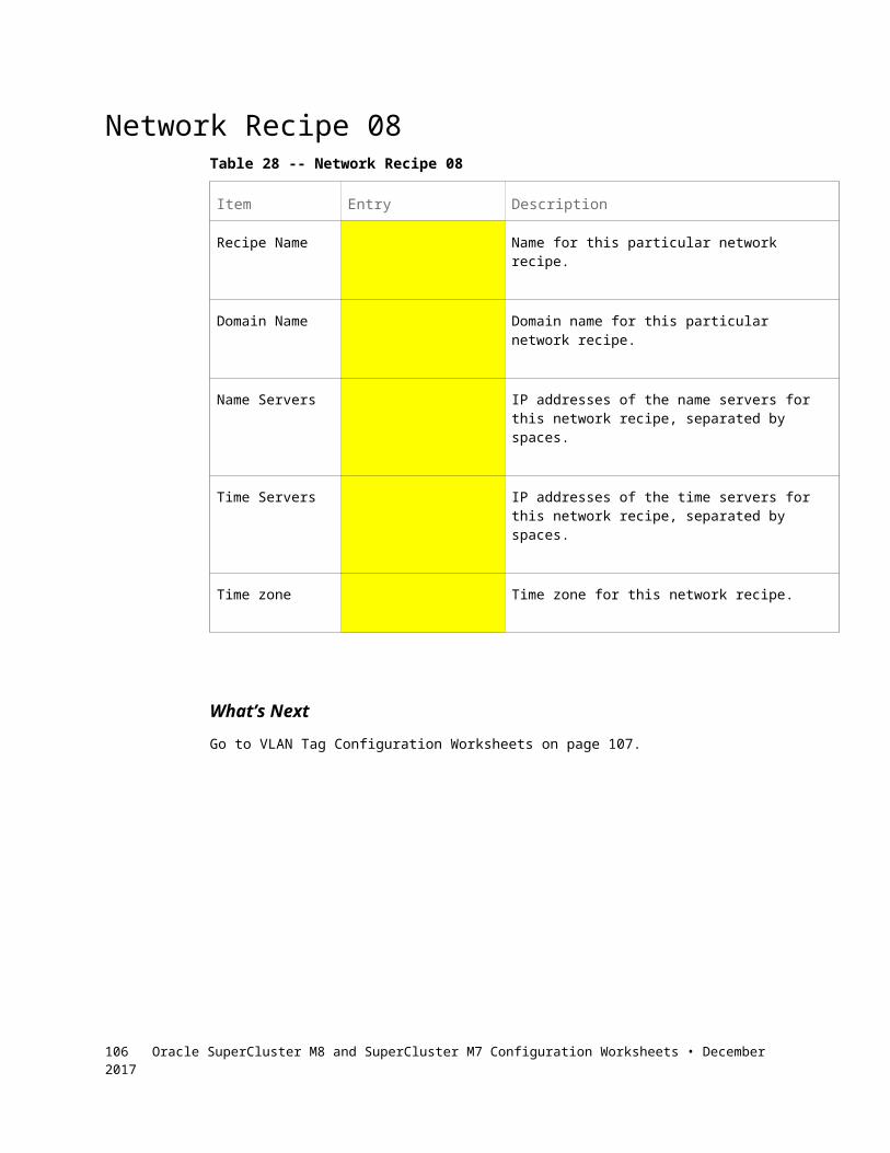
Table 59 -- RAC Cluster 30
Item Entry Description and Example
Client Network The client network that you want to use for this cluster. See the information that you provided in Client Access Networks Configuration Worksheets on page 75 for more information on the available client networks.Example: Client network 1
Network Recipe The network recipe that you want to use for this cluster. See the information that you provided in Network Recipe Configuration Worksheets on page 80 for more information on the available network recipes.Example: Network recipe 1
VLAN The VLAN tag that you want to use for this cluster, if necessary. See VLAN Tag Configuration Worksheets on page 86 for more information on the available VLAN tags.Example: 101
Table 60 -- RAC Cluster 31
Item Entry Description and Example
Client Network The client network that you want to use for this cluster. See the information that you provided in Client Access Networks Configuration Worksheets on page 75 for more information on the available client networks.Example: Client network 1
Network Recipe The network recipe that you want to use for this cluster. See the information that you provided in Network Recipe Configuration Worksheets on page 80 for more information on the available network recipes.Example: Network recipe 1
VLAN The VLAN tag that you want to use for this cluster, if necessary. See VLAN Tag Configuration Worksheets on page 86 for more information on the available VLAN tags.Example: 101
106 Oracle SuperCluster M8 and SuperCluster M7 Configuration Worksheets • December 2017

Table 61 -- RAC Cluster 32
Item Entry Description and Example
Client Network The client network that you want to use for this cluster. See the information that you provided in Client Access Networks Configuration Worksheets on page 75 for more information on the available client networks.Example: Client network 1
Network Recipe The network recipe that you want to use for this cluster. See the information that you provided in Network Recipe Configuration Worksheets on page 80 for more information on the available network recipes.Example: Network recipe 1
VLAN The VLAN tag that you want to use for this cluster, if necessary. See VLAN Tag Configuration Worksheets on page 86 for more information on the available VLAN tags.Example: 101
What’s NextGo to PDomain 0 on Compute Server 1: Configuration Worksheets on page 108 to provide LDom configuration information and CPU and memory resource allocation information for PDomain 0 on compute server 1.
107
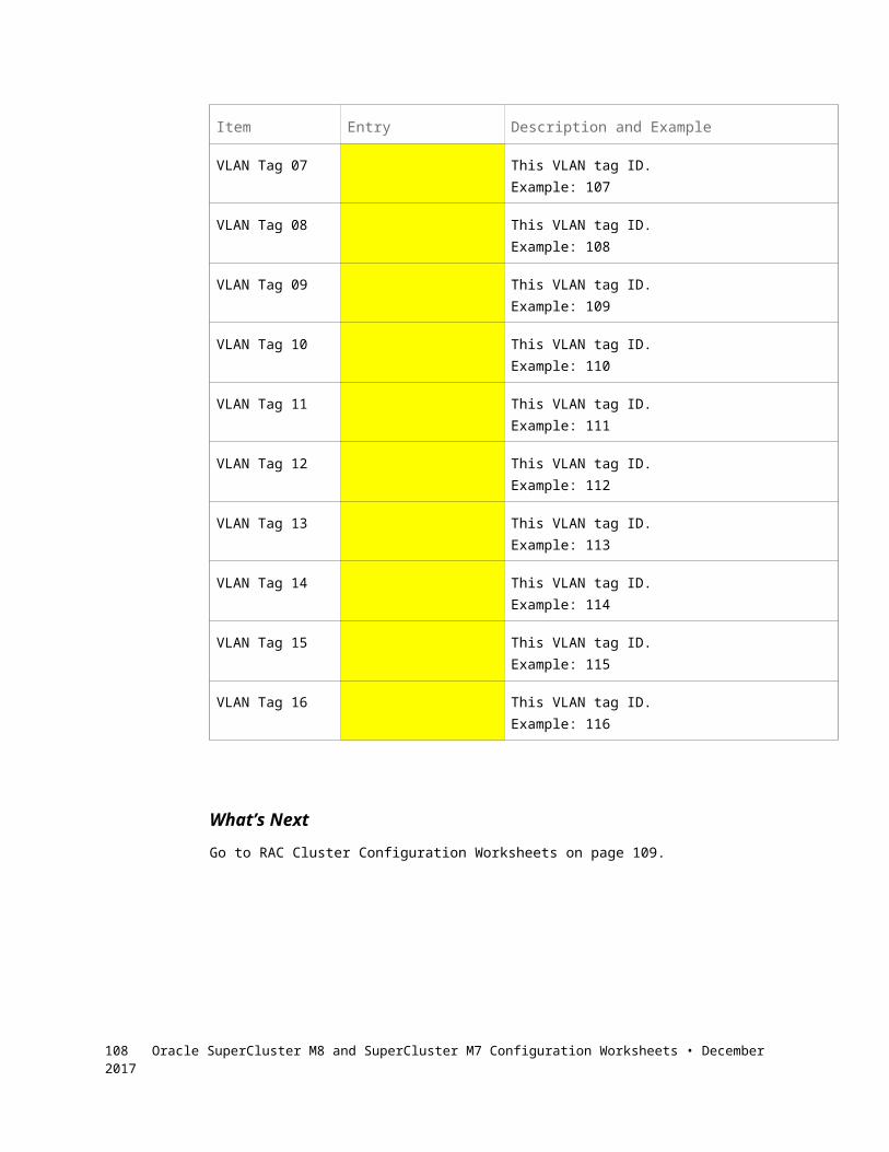
Chapter
1PDomain 0 on Compute Server 1:
Configuration WorksheetsComplete the worksheets in this chapter to provide this information for PDomain 0 in compute server 1:
Number of LDoms in this PDomain Type of LDoms in this PDomain:
Application Domain running the Oracle Solaris 11 OS (dedicated domain)
Database Domain (dedicated domain), with or without zones9
Root Domain, with some I/O Domains set up at the initial installation9
Note – Only Database Domains that are dedicated domains can host database zones. Database I/O Domains cannot host database zones.
Note – Refer to the Oracle SuperCluster M8 and SuperCluster M7 Overview Guide for more detailed information on the different configurations available.
Amount of CPU resources that you want to allocate to each LDom in this PDomain
Amount of memory resources that you want allocated to each LDom in this PDomain
Either of the following for each LDom in this PDomain: o Which cluster that you want for each Database Domain or
database zone, with that cluster’s client network, network recipe and VLAN tagging configurations, or
o Specific client network, network recipe and VLAN tagging configurations for each non-cluster LDom
9 See Oracle Setup of Database Zones and I/O Domains Overview on page 20 for more information on the maximum number of database zones and I/O Domains that can be set up by your Oracle installer.108 Oracle SuperCluster M8 and SuperCluster M7 Configuration Worksheets • December 2017

Enter the configuration information for PDomain 0 on compute server 1 in the tables in the appropriate section, depending on the number of CMIOUs that you have in this PDomain.
Check One Box PDomain 0 on Compute Server 1 Configuration
PDomain With One CMIOU on page 109
PDomain With Two CMIOUs on page 112
PDomain With Three CMIOUs on page 115
PDomain With Four CMIOUs on page 118
PDomain With One CMIOUEnter this configuration information if PDomain 0 in compute server 1 has one CMIOU:
LDom Configuration on page 109 CPU Resource Allocation on page 110 Memory Resource Allocation on page 110 Client Access Network, Network Recipe, VLAN Tag and Cluster
Information on page 110 Database Zone Information on page 111
LDom ConfigurationRead and understand the information in LDom Configurations For PDomains With One CMIOU on page 22 before completing the worksheets in this section.
Table 62 -- PDomain 0 In Compute Server 1 Configuration Worksheet: One CMIOUType of Domain on PDomain 0 on Compute Server 1
109

CPU Resource AllocationRead and understand the information in CPU Resource Allocation For PDomains With One CMIOU on page 31 before completing the worksheets in this section.
Table 63 -- PDomain 0 in Compute Server 1 Configuration Worksheet: One CMIOUCPU Resource Allocation for PDomain 0 in Compute Server 1 Total Number of Cores
Note - Total number of cores must be 32, unless some resources are parked.
Memory Resource AllocationRead and understand the information in Memory Resource Allocation For PDomains With One CMIOU on page 41 before completing the worksheets in this section.
Table 64 -- PDomain 0 in Compute Server 1 Configuration Worksheet: One CMIOUMemory Resource Allocation for PDomain 0 in Compute Server 1 Total Amount of Memory
Note - Total amount of memory resources must be 960 GB (SuperCluster M8) or 480 GB (SuperCluster M7), unless some
resources are parked.
Client Access Network, Network Recipe, VLAN Tag and Cluster InformationRead and understand the information in Understanding Client Access Network, Network Recipe, VLAN Tag, and RAC Cluster Options on page 47 before completing the worksheets in this section.
For every RAC Cluster in your SuperCluster, you provided client network, network recipe, and VLAN tagging information in RAC Cluster Configuration Worksheets on page 88. Any Database Domain or database zone that is a member of a RAC cluster automatically gets assigned IP addresses from that RAC cluster’s client access network and has that cluster’s network recipe and VLAN tagging information. Therefore:
If an LDom is a member of a RAC cluster, enter that RAC cluster number here. It will automatically get IP addresses from that RAC cluster’s client access network and will use that cluster’s network recipe and VLAN tagging information.
If an LDom is not a member of a RAC cluster, enter the following:o Client network number that you want to use for this LDom
110 Oracle SuperCluster M8 and SuperCluster M7 Configuration Worksheets • December 2017

o Network recipe that you want to use for this LDomo VLAN tagging information, if necessary, for this LDom
Table 65 -- PDomain 0 In Compute Server 1 Configuration Worksheet: One CMIOUType of Domain on PDomain 0 on Compute Server 1
Cluster number: OR
Client network number: Network recipe:
VLAN tag:
Database Zone InformationIf this LDom is a Database Domain with zones, your Oracle installer can set up a maximum of eight zones on this Database Domain during the initial installation. Your Oracle installer will also set up the RAC clusters for the zones in this Database Domain, where multiple zones within this Database Domain could be clustered together, or could be clustered together with zones in other Database Domains.
For every RAC cluster in your SuperCluster, you provided client network, network recipe, and VLAN tagging information in RAC Cluster Configuration Worksheets on page 88. Any database zone that is a member of a RAC cluster automatically gets assigned IP addresses from that RAC cluster’s client access network and has that cluster’s network recipe and VLAN tagging information.
Table 66 – Zone RAC Assignments
For each zone in this Database Domain, enter the RAC cluster number that you want that zone to be a member of.
Database Zones Cluster Number Database Zones Cluster Number
Zone 1 Zone 5
Zone 2 Zone 6
Zone 3 Zone 7
Zone 4 Zone 8
What’s Next If the second PDomain (PDomain 1) in compute server 1 is populated with
CMIOUs, go to PDomain 1 on Compute Server 1: Configuration Worksheets on page 124 to provide LDom configuration information and CPU and memory resource allocation information for PDomain 1 in compute server 1.
111

If the second PDomain in compute server 1 is not populated, go to PDomain 0 on Compute Server 2: Configuration Worksheets on page 139 to provide LDom configuration information and CPU and memory resource allocation information for PDomain 0 in compute server 2.
PDomain With Two CMIOUsEnter this configuration information if PDomain 0 in compute server 1 has two CMIOUs:
LDom Configurations on page 112 CPU Resource Allocation on page 112 Memory Resource Allocation on page 113 Client Access Network, Network Recipe, VLAN Tag and Cluster
Information on page 113 Database Zone Information on page 114
LDom ConfigurationsRead and understand the information in LDom Configurations For PDomains With Two CMIOUs on page 22 before completing the worksheets in this section.
Table 67 -- PDomain 0 in Compute Server 1 Configuration Worksheet: Two CMIOUs
Number and Type of Domains on PDomain 0 in Compute Server 1
Check One Box Config One Two
U2-1
U2-2
CPU Resource AllocationRead and understand the information in CPU Resource Allocation For PDomains With Two CMIOUs on page 32 before completing the worksheets in this section.
Table 68 -- PDomain 0 in Compute Server 1 Configuration Worksheet: Two CMIOUs
Check One Box
Config
CPU Resource Allocation for PDomain 0 in Compute Server 1Total Number of
CoresOne Two
U2-1
U2-2
Note - Total number of cores must be 64, unless some resources are parked.
112 Oracle SuperCluster M8 and SuperCluster M7 Configuration Worksheets • December 2017

Memory Resource AllocationRead and understand the information in Memory Resource Allocation For PDomains With Two CMIOUs on page 42 before completing the worksheets in this section.
Table 69 -- PDomain 0 in Compute Server 1 Configuration Worksheet: Two CMIOUs
Check One Box
Config
Memory Resource Allocation for PDomain 0 in Compute Server 1Total Amount of
MemoryOne Two
U2-1
U2-2
Note - Total amount of memory resources must be 1920 GB (SuperCluster M8) or 960 GB (SuperCluster M7), unless some resources are parked.
Client Access Network, Network Recipe, VLAN Tag and Cluster InformationRead and understand the information in Understanding Client Access Network, Network Recipe, VLAN Tag, and RAC Cluster Options on page 47 before completing the worksheets in this section.
For every RAC cluster in your SuperCluster, you provided client network, network recipe, and VLAN tagging information in RAC Cluster Configuration Worksheets on page 88. Any Database Domain or database zone that is a member of a RAC cluster automatically gets assigned IP addresses from that RAC cluster’s client access network and has that cluster’s network recipe and VLAN tagging information. Therefore:
If an LDom is a member of a RAC cluster, enter that RAC cluster number here. It will automatically get IP addresses from that RAC cluster’s client access network and will use that cluster’s network recipe and VLAN tagging information.
If an LDom is not a member of a RAC cluster, enter the following:o Client network number that you want to use for this LDomo Network recipe that you want to use for this LDomo VLAN tagging information, if necessary, for this LDom
113

Table 70 -- PDomain 0 in Compute Server 1 Configuration Worksheet: Two CMIOUs
Number and Type of Domains on PDomain 0 in Compute Server 1
Check One Box Config One Two
U2-1
Cluster number: OR
Client network number: Network recipe:
VLAN tag:
U2-2
Cluster number: OR
Client network number: Network recipe:
VLAN tag:
Cluster number: OR
Client network number: Network recipe:
VLAN tag:
Database Zone InformationIf this LDom is a Database Domain with zones, your Oracle installer can set up a maximum of eight zones on this Database Domain during the initial installation. Your Oracle installer will also set up the RAC clusters for the zones in this Database Domain, where multiple zones within this Database Domain could be clustered together, or could be clustered together with zones in other Database Domains.
For every RAC cluster in your SuperCluster, you provided client network, network recipe, and VLAN tagging information in RAC Cluster Configuration Worksheets on page 88. Any database zone that is a member of a RAC cluster automatically gets assigned IP addresses from that RAC cluster’s client access network and has that cluster’s network recipe and VLAN tagging information.
For each zone in this Database Domain, enter the RAC cluster number that you want that zone to be a member of.
Table 71 -- Zone RAC Assignments
Database Zones Cluster Number Database Zones Cluster Number
Zone 1 Zone 5
Zone 2 Zone 6
Zone 3 Zone 7
Zone 4 Zone 8
114 Oracle SuperCluster M8 and SuperCluster M7 Configuration Worksheets • December 2017

What’s Next If the second PDomain (PDomain 1) in compute server 1 is populated with
CMIOUs, go to PDomain 1 on Compute Server 1: Configuration Worksheets on page 124 to provide LDom configuration information and CPU and memory resource allocation information for PDomain 1 in compute server 1.
If the second PDomain in compute server 1 is not populated, go to PDomain 0 on Compute Server 2: Configuration Worksheets on page 139 to provide LDom configuration information and CPU and memory resource allocation information for PDomain 0 in compute server 2.
PDomain With Three CMIOUsEnter this configuration information if PDomain 0 in compute server 1 has three CMIOUs:
LDom Configurations on page 115 CPU Resource Allocation on page 116 Memory Resource Allocation on page 116 Client Access Network, Network Recipe, VLAN Tag and Cluster
Information on page 117 Database Zone Information on page 118
LDom ConfigurationsRead and understand the information in LDom Configurations For PDomains With Three CMIOUs on page 24 before completing the worksheets in this section.
Table 72 -- PDomain 0 in Compute Server 1 Configuration Worksheet: Three CMIOUs
Number and Type of LDoms on PDomain 0 in Compute Server 1
Check One Box Config One Two Three
U3-1
U3-2
U3-3
115

CPU Resource AllocationRead and understand the information in CPU Resource Allocation For PDomains With Three CMIOUs on page 33 before completing the worksheets in this section.
Table 73 -- PDomain 0 in Compute Server 1 Configuration Worksheet: Three CMIOUs
CPU Resource Allocation for PDomain 0 in Compute Server 1
Check One Box Config One Two Three
Total Number of Cores
U3-1
U3-2
U3-3
Note - Total number of cores must be 96, unless some resources are parked.
Memory Resource AllocationRead and understand the information in Memory Resource Allocation For PDomains With Three CMIOUs on page 43 before completing the worksheets in this section.
Table 74 -- PDomain 0 in Compute Server 1 Configuration Worksheet: Three CMIOUs
Memory Resource Allocation for PDomain 0 in Compute Server 1
Check One Box Config One Two Three
Total Amount of Memory
U3-1
U3-2
U3-3
Note - Total amount of memory must be 2880 GB (SuperCluster M8) or 1440 GB (SuperCluster M7), unless some resources are parked.
116 Oracle SuperCluster M8 and SuperCluster M7 Configuration Worksheets • December 2017

Client Access Network, Network Recipe, VLAN Tag and Cluster InformationRead and understand the information in Understanding Client Access Network, Network Recipe, VLAN Tag, and RAC Cluster Options on page 47 before completing the worksheets in this section.
For every RAC cluster in your SuperCluster, you provided client network, network recipe, and VLAN tagging information in RAC Cluster Configuration Worksheets on page 88. Any Database Domain or database zone that is a member of a RAC cluster automatically gets assigned IP addresses from that RAC cluster’s client access network and has that cluster’s network recipe and VLAN tagging information. Therefore:
If an LDom is a member of a RAC cluster, enter that RAC cluster number here. It will automatically get IP addresses from that RAC cluster’s client access network and will use that cluster’s network recipe and VLAN tagging information.
If an LDom is not a member of a RAC cluster, enter the following:o Client network number that you want to use for this LDomo Network recipe that you want to use for this LDomo VLAN tagging information, if necessary, for this LDom
Table 75 -- PDomain 0 in Compute Server 1 Configuration Worksheet: Three CMIOUs
Number and Type of LDoms on PDomain 0 in Compute Server 1
Check One Box Config One Two Three
U3-1
Cluster number: OR
Client network number: Network recipe:
VLAN tag:
U3-2
Cluster number: OR
Client network number: Network recipe:
VLAN tag:
Cluster number: OR
Client network number:
Network recipe: VLAN tag:
U3-3
Cluster number: OR
Client network number:
Network recipe: VLAN tag:
Cluster number: OR
Client network number:
Network recipe: VLAN tag:
Cluster number: OR
Client network number:
Network recipe: VLAN tag:
117

Database Zone InformationIf this LDom is a Database Domain with zones, your Oracle installer can set up a maximum of eight zones on this Database Domain during the initial installation. Your Oracle installer will also set up the RAC clusters for the zones in this Database Domain, where multiple zones within this Database Domain could be clustered together, or could be clustered together with zones in other Database Domains.
For every RAC cluster in your SuperCluster, you provided client network, network recipe, and VLAN tagging information in RAC Cluster Configuration Worksheets on page 88. Any database zone that is a member of a RAC cluster automatically gets assigned IP addresses from that RAC cluster’s client access network and has that cluster’s network recipe and VLAN tagging information.
For each zone in this Database Domain, enter the RAC cluster number that you want that zone to be a member of.
Table 76 -- Zone RAC Assignments
Database Zones Cluster Number Database Zones Cluster Number
Zone 1 Zone 5
Zone 2 Zone 6
Zone 3 Zone 7
Zone 4 Zone 8
What’s Next If the second PDomain (PDomain 1) in compute server 1 is populated with
CMIOUs, go to PDomain 1 on Compute Server 1: Configuration Worksheets on page 124 to provide LDom configuration information and CPU and memory resource allocation information for PDomain 1 in compute server 1.
If the second PDomain in compute server 1 is not populated, go to PDomain 0 on Compute Server 2: Configuration Worksheets on page 139 to provide LDom configuration information and CPU and memory resource allocation information for PDomain 0 in compute server 2.
PDomain With Four CMIOUsEnter this configuration information if PDomain 0 in compute server 1 has four CMIOUs:
LDom Configurations on page 119 CPU Resource Allocation on page 119 Memory Resource Allocation on page 120 Client Access Network, Network Recipe, VLAN Tag and Cluster
118 Oracle SuperCluster M8 and SuperCluster M7 Configuration Worksheets • December 2017

Information on page 120 Database Zone Information on page 121
LDom ConfigurationsRead and understand the information in LDom Configurations For PDomains With Four CMIOUs on page 26 before completing the worksheets in this section.
Table 77 -- PDomain 0 in Compute Server 1 Configuration Worksheet: Four CMIOUs
Number and Type of Domains on PDomain 0 in Compute Server 1
Check One Box Config One Two Three Four
U4-1
U4-2
U4-3
U4-4
CPU Resource AllocationRead and understand the information in CPU Resource Allocation For PDomains With Four CMIOUs on page 35 before completing the worksheets in this section.
Table 78 -- PDomain 0 in Compute Server 1 Configuration Worksheet: Four CMIOUs
CPU Resource Allocation for PDomain 0 in Compute Server 1
Check One Box Config One Two Three Four
Total Number of
Cores
U4-1
U4-2
U4-3
U4-4
Note - Total number of cores must be 128, unless some resources are parked.
119

Memory Resource AllocationRead and understand the information in Memory Resource Allocation For PDomains With Four CMIOUs on page 44 before completing the worksheets in this section.
Table 79 -- PDomain 0 in Compute Server 1 Configuration Worksheet: Four CMIOUs
Memory Resource Allocation for PDomain 0 in Compute Server 1
Check One Box Config One Two Three Four
Total Amount of Memory
U4-1
U4-2
U4-3
U4-4
Note - Total amount of memory resources must be 3840 (SuperCluster M8) or 1980 GB (SuperCluster M7), unless some resources are parked.
Client Access Network, Network Recipe, VLAN Tag and Cluster InformationRead and understand the information in Understanding Client Access Network, Network Recipe, VLAN Tag, and RAC Cluster Options on page 47 before completing the worksheets in this section.
For every RAC cluster in your SuperCluster, you provided client network, network recipe, and VLAN tagging information in RAC Cluster Configuration Worksheets on page 88. Any Database Domain or database zone that is a member of a RAC cluster automatically gets assigned IP addresses from that RAC cluster’s client access network and has that cluster’s network recipe and VLAN tagging information. Therefore:
If an LDom is a member of a RAC cluster, enter that RAC cluster number here. It will automatically get IP addresses from that RAC cluster’s client access network and will use that cluster’s network recipe and VLAN tagging information.
If an LDom is not a member of a RAC cluster, enter the following:o Client network number that you want to use for this LDomo Network recipe that you want to use for this LDomo VLAN tagging information, if necessary, for this LDom
120 Oracle SuperCluster M8 and SuperCluster M7 Configuration Worksheets • December 2017

Table 80 -- PDomain 0 in Compute Server 1 Configuration Worksheet: Four CMIOUs
Number and Type of Domains on PDomain 0 in Compute Server 1
Check One Box Config One Two Three Four
U4-1
Cluster number: OR
Client network number: Network recipe:
VLAN tag:
U4-2
Cluster number: OR
Client network number: Network recipe:
VLAN tag:
Cluster number: OR
Client network number: Network recipe:
VLAN tag:
U4-3
Cluster number: OR
Client network number: Network recipe:
VLAN tag:
Cluster number: OR
Client network number:
Network recipe: VLAN tag:
Cluster number:
OR Client
network number: Network recipe:
VLAN tag:
U4-4
Cluster number: OR
Client network number:
Network recipe: VLAN tag:
Cluster number: OR
Client network number:
Network recipe: VLAN tag:
Cluster number: OR
Client network number:
Network recipe: VLAN tag:
Cluster number:
OR Client
network number: Network recipe:
VLAN tag:
Database Zone InformationIf this LDom is a Database Domain with zones, your Oracle installer can set up a maximum of eight zones on this Database Domain during the initial installation. Your Oracle installer will also set up the RAC clusters for the zones in this Database Domain, where multiple zones within this Database Domain could be clustered together, or could be clustered together with zones in other Database Domains.
121

For every RAC cluster in your SuperCluster, you provided client network, network recipe, and VLAN tagging information in RAC Cluster Configuration Worksheets on page 88. Any database zone that is a member of a RAC cluster automatically gets assigned IP addresses from that RAC cluster’s client access network and has that cluster’s network recipe and VLAN tagging information.
For each zone in this Database Domain, enter the RAC cluster number that you want that zone to be a member of.
Table 81 -- Zone RAC Assignments
Database Zones Cluster Number Database Zones Cluster Number
Zone 1 Zone 5
Zone 2 Zone 6
Zone 3 Zone 7
Zone 4 Zone 8
What’s Next If the second PDomain (PDomain 1) in compute server 1 is populated with
CMIOUs, go to PDomain 1 on Compute Server 1: Configuration Worksheets on page 124 to provide LDom configuration information and CPU and memory resource allocation information for PDomain 1 in compute server 1.
If the second PDomain in compute server 1 is not populated, go to PDomain 0 on Compute Server 2: Configuration Worksheets on page 139 to provide LDom configuration information and CPU and memory resource allocation information for PDomain 0 in compute server 2.
122 Oracle SuperCluster M8 and SuperCluster M7 Configuration Worksheets • December 2017

123

Chapter
1PDomain 1 on Compute Server 1:
Configuration WorksheetsComplete the worksheets in this chapter to provide this information for PDomain 1 in compute server 1:
Number of LDoms in this PDomain Type of LDoms in this PDomain:
Application Domain running the Oracle Solaris 11 OS (dedicated domain)
Database Domain (dedicated domain), with or without zones10
Root Domain, with some I/O Domains set up at the initial installation10
Note – Only Database Domains that are dedicated domains can host database zones. Database I/O Domains cannot host database zones.
Note – Refer to the Oracle SuperCluster M8 and SuperCluster M7 Overview Guide for more detailed information on the different configurations available.
Amount of CPU resources that you want to allocate to each LDom in this PDomain
Amount of memory resources that you want allocated to each LDom in this PDomain
Either of the following for each LDom in this PDomain: o Which RAC cluster that you want for each Database Domain or
database zone, with that RAC cluster’s client network, network recipe and VLAN tagging configurations, or
o Specific client network, network recipe and VLAN tagging configurations for each non-RAC cluster LDom
10 See Oracle Setup of Database Zones and I/O Domains Overview on page 20 for more information on the maximum number of database zones and I/O Domains that can be set up by your Oracle installer.124 Oracle SuperCluster M8 and SuperCluster M7 Configuration Worksheets • December 2017

Enter the configuration information for PDomain 1 on compute server 1 in these tables, depending on the number of CMIOUs that you have in this PDomain:
Check One Box PDomain 1 on Compute Server 1 Configuration
PDomain With One CMIOU on page 125
PDomain With Two CMIOUs on page 128PDomain With Three CMIOUs on page 131PDomain With Four CMIOUs on page 134
PDomain With One CMIOUEnter this configuration information if PDomain 1 in compute server 1 has one CMIOU:
LDom Configurations on page 125 CPU Resource Allocation on page 126 Memory Resource Allocation on page 126 Client Access Network, Network Recipe, VLAN Tag and Cluster
Information on page 126 Database Zone Information on page 127
LDom ConfigurationsRead and understand the information in LDom Configurations For PDomains With One CMIOU on page 22 before completing the worksheets in this section.
Table 82 -- PDomain 1 In Compute Server 1 Configuration Worksheet: One CMIOUType of Domain on PDomain 1 on Compute Server 1
125

CPU Resource AllocationRead and understand the information in CPU Resource Allocation For PDomains With One CMIOU on page 31 before completing the worksheets in this section.
Table 83 -- PDomain 1 in Compute Server 1 Configuration Worksheet: One CMIOUCPU Resource Allocation for PDomain 1 in Compute
Server 1Total Number of Cores
Note - Total number of cores must be 32, unless some resources are parked.
Memory Resource Allocation Read and understand the information in Memory Resource Allocation For PDomains With One CMIOU on page 41 before completing the worksheets in this section.
Table 84 -- PDomain 1 in Compute Server 1 Configuration Worksheet: One CMIOUMemory Resource Allocation for PDomain 1 in Compute Server 1 Total Amount of Memory
Note - Total amount of memory resources must be 960 GB (SuperCluster M8) or 480 GB (SuperCluster M7), unless some
resources are parked.
Client Access Network, Network Recipe, VLAN Tag and Cluster InformationRead and understand the information in Understanding Client Access Network, Network Recipe, VLAN Tag, and RAC Cluster Options on page 47 before completing the worksheets in this section.
For every RAC cluster in your SuperCluster, you provided client network, network recipe, and VLAN tagging information in RAC Cluster Configuration Worksheets on page 88. Any Database Domain or database zone that is a member of a RAC cluster automatically gets assigned IP addresses from that RAC cluster’s client access network and has that cluster’s network recipe and VLAN tagging information. Therefore:
If an LDom is a member of a RAC cluster, enter that RAC cluster number here. It will automatically get IP addresses from that RAC cluster’s client access network and will use that cluster’s network recipe and VLAN tagging information.
126 Oracle SuperCluster M8 and SuperCluster M7 Configuration Worksheets • December 2017
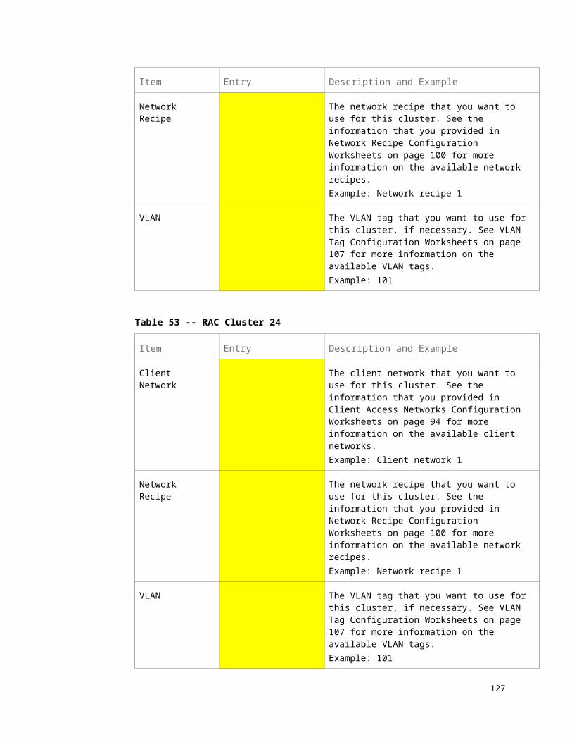
If an LDom is not a member of a RAC cluster, enter the following:o Client network number that you want to use for this LDomo Network recipe that you want to use for this LDomo VLAN tagging information, if necessary, for this LDom
Table 85 -- PDomain 1 In Compute Server 1 Configuration Worksheet: One CMIOUType of Domain on PDomain 1 on Compute Server 1
Cluster number: OR
Client network number: Network recipe:
VLAN tag:
Database Zone InformationIf this LDom is a Database Domain with zones, your Oracle installer can set up a maximum of eight zones on this Database Domain during the initial installation. Your Oracle installer will also set up the RAC clusters for the zones in this Database Domain, where multiple zones within this Database Domain could be clustered together, or could be clustered together with zones in other Database Domains.
For every RAC cluster in your SuperCluster, you provided client network, network recipe, and VLAN tagging information in RAC Cluster Configuration Worksheets on page 88. Any database zone that is a member of a RAC cluster automatically gets assigned IP addresses from that RAC cluster’s client access network and has that cluster’s network recipe and VLAN tagging information.
For each zone in this Database Domain, enter the RAC cluster number that you want that zone to be a member of.
Table 86 -- Zone RAC Assignments
Database Zones Cluster Number Database Zones Cluster Number
Zone 1 Zone 5
Zone 2 Zone 6
Zone 3 Zone 7
Zone 4 Zone 8
What’s Next If your SuperCluster M8 or SuperCluster M7 has two compute servers, go
to PDomain 0 on Compute Server 2: Configuration Worksheets on page 139 to provide LDom configuration information and CPU and memory
127

resource allocation information for PDomain 0 in compute server 2.
If your SuperCluster M8 or SuperCluster M7 does not have two compute servers, go to Completing the General Configuration Worksheets on page 169.
PDomain With Two CMIOUsEnter this configuration information if PDomain 1 in compute server 1 has two CMIOUs:
LDom Configurations on page 128 CPU Resource Allocation on page 128 Memory Resource Allocation on page 129 Client Access Network, Network Recipe, VLAN Tag and Cluster
Information on page 129 Database Zone Information on page 130
LDom ConfigurationsRead and understand the information in LDom Configurations For PDomains With Two CMIOUs on page 22 before completing the worksheets in this section.
Table 87 -- PDomain 1 in Compute Server 1 Configuration Worksheet: Two CMIOUs
Number and Type of Domains on PDomain 1 in Compute Server 1
Check One Box Config One Two
U2-1
U2-2
CPU Resource AllocationRead and understand the information in CPU Resource Allocation For PDomains With Two CMIOUs on page 32 before completing the worksheets in this section.
Table 88 -- PDomain 1 in Compute Server 1 Configuration Worksheet: Two CMIOUs
Check One Box
Config
CPU Resource Allocation for PDomain 1 in Compute Server 1Total Number of
CoresOne Two
U2-1
U2-2
128 Oracle SuperCluster M8 and SuperCluster M7 Configuration Worksheets • December 2017

Note - Total number of cores must be 64, unless some resources are parked.
Memory Resource AllocationRead and understand the information in Memory Resource Allocation For PDomains With Two CMIOUs on page 42 before completing the worksheets in this section.
Table 89 -- PDomain 1 in Compute Server 1 Configuration Worksheet: Two CMIOUs
Check One Box
Config
Memory Resource Allocation for PDomain 1 in Compute Server 1Total Amount of
MemoryOne Two
U2-1
U2-2
Note - Total amount of memory resources must be 1920 GB (SuperCluster M8) or 960 GB (SuperCluster M7), unless some resources are parked.
Client Access Network, Network Recipe, VLAN Tag and Cluster InformationRead and understand the information in Understanding Client Access Network, Network Recipe, VLAN Tag, and RAC Cluster Options on page 47 before completing the worksheets in this section.
For every RAC cluster in your SuperCluster, you provided client network, network recipe, and VLAN tagging information in RAC Cluster Configuration Worksheets on page 88. Any Database Domain or database zone that is a member of a RAC cluster automatically gets assigned IP addresses from that RAC cluster’s client access network and has that cluster’s network recipe and VLAN tagging information. Therefore:
If an LDom is a member of a RAC cluster, enter that RAC cluster number here. It will automatically get IP addresses from that RAC cluster’s client access network and will use that cluster’s network recipe and VLAN tagging information.
If an LDom is not a member of a RAC cluster, enter the following:o Client network number that you want to use for this LDomo Network recipe that you want to use for this LDomo VLAN tagging information, if necessary, for this LDom
129

Table 90 -- PDomain 1 in Compute Server 1 Configuration Worksheet: Two CMIOUs
Number and Type of Domains on PDomain 1 in Compute Server 1
Check One Box Config One Two
U2-1
Cluster number: OR
Client network number: Network recipe:
VLAN tag:
U2-2
Cluster number: OR
Client network number: Network recipe:
VLAN tag:
Cluster number: OR
Client network number: Network recipe:
VLAN tag:
Database Zone InformationIf this LDom is a Database Domain with zones, your Oracle installer can set up a maximum of eight zones on this Database Domain during the initial installation. Your Oracle installer will also set up the RAC clusters for the zones in this Database Domain, where multiple zones within this Database Domain could be clustered together, or could be clustered together with zones in other Database Domains.
For every RAC cluster in your SuperCluster, you provided client network, network recipe, and VLAN tagging information in RAC Cluster Configuration Worksheets on page 88. Any database zone that is a member of a RAC cluster automatically gets assigned IP addresses from that RAC cluster’s client access network and has that cluster’s network recipe and VLAN tagging information.
For each zone in this Database Domain, enter the RAC cluster number that you want that zone to be a member of.
Table 91 -- Zone RAC Assignments
Database Zones Cluster Number Database Zones Cluster Number
Zone 1 Zone 5
Zone 2 Zone 6
Zone 3 Zone 7
Zone 4 Zone 8
130 Oracle SuperCluster M8 and SuperCluster M7 Configuration Worksheets • December 2017

What’s Next If your SuperCluster M8 or SuperCluster M7 has two compute servers, go
to PDomain 0 on Compute Server 2: Configuration Worksheets on page 139 to provide LDom configuration information and CPU and memory resource allocation information for PDomain 0 in compute server 2.
If your SuperCluster M8 or SuperCluster M7 does not have two compute servers, go to Completing the General Configuration Worksheets on page 169.
PDomain With Three CMIOUsEnter this configuration information if PDomain 1 in compute server 1 has three CMIOUs:
LDom Configurations on page 131 CPU Resource Allocation on page 132 Memory Resource Allocation on page 132 Client Access Network, Network Recipe, VLAN Tag and Cluster
Information on page 133 Database Zone Information on page 134
LDom ConfigurationsRead and understand the information in LDom Configurations For PDomains With Three CMIOUs on page 24 before completing the worksheets in this section.
Table 92 -- PDomain 1 in Compute Server 1 Configuration Worksheet: Three CMIOUs
Number and Type of LDoms on PDomain 1 in Compute Server 1
Check One Box Config One Two Three
U3-1
U3-2
U3-3
131

CPU Resource AllocationRead and understand the information in CPU Resource Allocation For PDomains With Three CMIOUs on page 33 before completing the worksheets in this section.
Table 93 -- PDomain 1 in Compute Server 1 Configuration Worksheet: Three CMIOUs
CPU Resource Allocation for PDomain 1 in Compute Server 1
Check One Box Config One Two Three
Total Number of Cores
U3-1
U3-2
U3-3
Note - Total number of cores must be 96, unless some resources are parked.
Memory Resource AllocationRead and understand the information in Memory Resource Allocation For PDomains With Three CMIOUs on page 43 before completing the worksheets in this section.
Table 94 -- PDomain 1 in Compute Server 1 Configuration Worksheet: Three CMIOUs
Memory Resource Allocation for PDomain 1 in Compute Server 1
Check One Box Config One Two Three
Total Amount of Memory
U3-1
U3-2
U3-3
Note - Total amount of memory must be 2880 GB (SuperCluster M8) or 1440 GB (SuperCluster M7), unless some resources are parked.
132 Oracle SuperCluster M8 and SuperCluster M7 Configuration Worksheets • December 2017

Client Access Network, Network Recipe, VLAN Tag and Cluster InformationRead and understand the information in Understanding Client Access Network, Network Recipe, VLAN Tag, and RAC Cluster Options on page 47 before completing the worksheets in this section.
For every RAC cluster in your SuperCluster, you provided client network, network recipe, and VLAN tagging information in RAC Cluster Configuration Worksheets on page 88. Any Database Domain or database zone that is a member of a RAC cluster automatically gets assigned IP addresses from that RAC cluster’s client access network and has that cluster’s network recipe and VLAN tagging information. Therefore:
If an LDom is a member of a RAC cluster, enter that RAC cluster number here. It will automatically get IP addresses from that RAC cluster’s client access network and will use that cluster’s network recipe and VLAN tagging information.
If an LDom is not a member of a RAC cluster, enter the following:o Client network number that you want to use for this LDomo Network recipe that you want to use for this LDomo VLAN tagging information, if necessary, for this LDom
Table 95 -- PDomain 1 in Compute Server 1 Configuration Worksheet: Three CMIOUs
Number and Type of LDoms on PDomain 1 in Compute Server 1
Check One Box Config One Two Three
U3-1
Cluster number: OR
Client network number: Network recipe:
VLAN tag:
U3-2
Cluster number: OR
Client network number: Network recipe:
VLAN tag:
Cluster number: OR
Client network number:
Network recipe: VLAN tag:
U3-3
Cluster number: OR
Client network number:
Network recipe: VLAN tag:
Cluster number: OR
Client network number:
Network recipe: VLAN tag:
Cluster number: OR
Client network number:
Network recipe: VLAN tag:
133

Database Zone InformationIf this LDom is a Database Domain with zones, your Oracle installer can set up a maximum of eight zones on this Database Domain during the initial installation. Your Oracle installer will also set up the RAC clusters for the zones in this Database Domain, where multiple zones within this Database Domain could be clustered together, or could be clustered together with zones in other Database Domains.
For every RAC cluster in your SuperCluster, you provided client network, network recipe, and VLAN tagging information in RAC Cluster Configuration Worksheets on page 88. Any database zone that is a member of a RAC cluster automatically gets assigned IP addresses from that RAC cluster’s client access network and has that cluster’s network recipe and VLAN tagging information.
For each zone in this Database Domain, enter the RAC cluster number that you want that zone to be a member of.
Table 96 -- Zone RAC Assignments
Database Zones Cluster Number Database Zones Cluster Number
Zone 1 Zone 5
Zone 2 Zone 6
Zone 3 Zone 7
Zone 4 Zone 8
What’s Next If your SuperCluster M8 or SuperCluster M7 has two compute servers, go
to PDomain 0 on Compute Server 2: Configuration Worksheets on page 139 to provide LDom configuration information and CPU and memory resource allocation information for PDomain 0 in compute server 2.
If your SuperCluster M8 or SuperCluster M7 does not have two compute servers, go to Completing the General Configuration Worksheets on page 169.
PDomain With Four CMIOUsEnter this configuration information if PDomain 1 in compute server 1 has four CMIOUs:
LDom Configurations on page 135 CPU Resource Allocation on page 135 Memory Resource Allocation on page 136 Client Access Network, Network Recipe, VLAN Tag and Cluster
134 Oracle SuperCluster M8 and SuperCluster M7 Configuration Worksheets • December 2017

Information on page 136 Database Zone Information on page 137
LDom ConfigurationsRead and understand the information in LDom Configurations For PDomains With Four CMIOUs on page 26 before completing the worksheets in this section.
Table 97 -- PDomain 1 in Compute Server 1 Configuration Worksheet: Four CMIOUs
Number and Type of Domains on PDomain 1 in Compute Server 1
Check One Box Config One Two Three Four
U4-1
U4-2
U4-3
U4-4
CPU Resource AllocationRead and understand the information in CPU Resource Allocation For PDomains With Four CMIOUs on page 35 before completing the worksheets in this section.
Table 98 -- PDomain 1 in Compute Server 1 Configuration Worksheet: Four CMIOUs
CPU Resource Allocation for PDomain 1 in Compute Server 1
Check One Box Config One Two Three Four
Total Number of
Cores
U4-1
U4-2
U4-3
U4-4
Note - Total number of cores must be 128, unless some resources are parked.
135

Memory Resource AllocationRead and understand the information in Memory Resource Allocation For PDomains With Four CMIOUs on page 44 before completing the worksheets in this section.
Table 99 -- PDomain 1 in Compute Server 1 Configuration Worksheet: Four CMIOUs
Memory Resource Allocation for PDomain 1 in Compute Server 1
Check One Box Config One Two Three Four
Total Amount of Memory
U4-1
U4-2
U4-3
U4-4
Note - Total amount of memory resources must be 3840 (SuperCluster M8) or 1980 GB (SuperCluster M7), unless some resources are parked.
Client Access Network, Network Recipe, VLAN Tag and Cluster InformationRead and understand the information in Understanding Client Access Network, Network Recipe, VLAN Tag, and RAC Cluster Options on page 47 before completing the worksheets in this section.
For every RAC cluster in your SuperCluster, you provided client network, network recipe, and VLAN tagging information in RAC Cluster Configuration Worksheets on page 88. Any Database Domain or database zone that is a member of a RAC cluster automatically gets assigned IP addresses from that RAC cluster’s client access network and has that cluster’s network recipe and VLAN tagging information. Therefore:
If an LDom is a member of a RAC cluster, enter that RAC cluster number here. It will automatically get IP addresses from that RAC cluster’s client access network and will use that cluster’s network recipe and VLAN tagging information.
If an LDom is not a member of a RAC cluster, enter the following:o Client network number that you want to use for this LDomo Network recipe that you want to use for this LDomo VLAN tagging information, if necessary, for this LDom
136 Oracle SuperCluster M8 and SuperCluster M7 Configuration Worksheets • December 2017

Table 100 -- PDomain 1 in Compute Server 1 Configuration Worksheet: Four CMIOUs
Number and Type of Domains on PDomain 1 in Compute Server 1
Check One Box Config One Two Three Four
U4-1
Cluster number: OR
Client network number: Network recipe:
VLAN tag:
U4-2
Cluster number: OR
Client network number: Network recipe:
VLAN tag:
Cluster number: OR
Client network number: Network recipe:
VLAN tag:
U4-3
Cluster number: OR
Client network number: Network recipe:
VLAN tag:
Cluster number: OR
Client network number:
Network recipe: VLAN tag:
Cluster number:
OR Client
network number: Network recipe:
VLAN tag:
U4-4
Cluster number: OR
Client network number:
Network recipe: VLAN tag:
Cluster number: OR
Client network number:
Network recipe: VLAN tag:
Cluster number: OR
Client network number:
Network recipe: VLAN tag:
Cluster number:
OR Client
network number: Network recipe:
VLAN tag:
Database Zone InformationIf this LDom is a Database Domain with zones, your Oracle installer can set up a maximum of eight zones on this Database Domain during the initial installation. Your Oracle installer will also set up the RAC clusters for the zones in this Database Domain, where multiple zones within this Database Domain could be clustered together, or could be clustered together with zones in other Database Domains.
For every RAC cluster in your SuperCluster, you provided client network, network recipe, and VLAN tagging information in RAC Cluster Configuration Worksheets on
137

page 88. Any database zone that is a member of a RAC cluster automatically gets assigned IP addresses from that RAC cluster’s client access network and has that cluster’s network recipe and VLAN tagging information.
For each zone in this Database Domain, enter the RAC cluster number that you want that zone to be a member of.
Table 101 -- Zone RAC Assignments
Database Zones Cluster Number Database Zones Cluster Number
Zone 1 Zone 5
Zone 2 Zone 6
Zone 3 Zone 7
Zone 4 Zone 8
What’s Next If your SuperCluster M8 or SuperCluster M7 has two compute servers, go
to PDomain 0 on Compute Server 2: Configuration Worksheets on page 139 to provide LDom configuration information and CPU and memory resource allocation information for PDomain 0 in compute server 2.
If your SuperCluster M8 or SuperCluster M7 does not have two compute servers, go to Completing the General Configuration Worksheets on page 169.
138 Oracle SuperCluster M8 and SuperCluster M7 Configuration Worksheets • December 2017

Chapter
1PDomain 0 on Compute Server 2:
Configuration WorksheetsComplete the worksheets in this chapter to provide this information for PDomain 0 in compute server 2:
Number of LDoms in this PDomain Type of LDoms in this PDomain:
Application Domain running the Oracle Solaris 11 OS (dedicated domain)
Database Domain (dedicated domain), with or without zones11
Root Domain, with some I/O Domains set up at the initial installation11
Note – Only Database Domains that are dedicated domains can host database zones. Database I/O Domains cannot host database zones.
Note – Refer to the Oracle SuperCluster M8 and SuperCluster M7 Overview Guide for more detailed information on the different configurations available.
Amount of CPU resources that you want to allocate to each LDom in this PDomain
Amount of memory resources that you want allocated to each LDom in this PDomain
Either of the following for each LDom in this PDomain: o Which RAC cluster that you want for each Database Domain or
database zone, with that RAC cluster’s client network, network recipe and VLAN tagging configurations, or
o Specific client network, network recipe and VLAN tagging configurations for each non-RAC cluster LDom
11 See Oracle Setup of Database Zones and I/O Domains Overview on page 20 for more information on the maximum number of database zones and I/O Domains that can be set up by your Oracle installer.
139

Enter the configuration information for PDomain 0 on compute server 2 in these tables, depending on the number of CMIOUs that you have in this PDomain:
Check One Box PDomain 0 on Compute Server 2 Configuration
PDomain With One CMIOU on page 140
PDomain With Two CMIOUs on page 143
PDomain With Three CMIOUs on page 146
PDomain With Four CMIOUs on page 149
PDomain With One CMIOUEnter this configuration information if PDomain 0 in compute server 2 has one CMIOU:
LDom Configurations on page 140 CPU Resource Allocation on page 141
Error: Reference source not found on page Error: Reference source not found
Client Access Network, Network Recipe, VLAN Tag and Cluster Information on page 141
Database Zone Information on page 142
LDom ConfigurationsRead and understand the information in LDom Configurations For PDomains With One CMIOU on page 22 before completing the worksheets in this section.
Table 102 -- PDomain 0 In Compute Server 2 Configuration Worksheet: One CMIOUType of Domain on PDomain 0 on Compute Server 2
140 Oracle SuperCluster M8 and SuperCluster M7 Configuration Worksheets • December 2017

CPU Resource AllocationRead and understand the information in CPU Resource Allocation For PDomains With One CMIOU on page 31 before completing the worksheets in this section.
Table 103 -- PDomain 0 in Compute Server 2 Configuration Worksheet: One CMIOUCPU Resource Allocation for PDomain 0 in Compute
Server 2Total Number of Cores
Note - Total number of cores must be 32, unless some resources are parked.
Memory Resource AllocationRead and understand the information in Memory Resource Allocation For PDomains With One CMIOU on page 41 before completing the worksheets in this section.
Table 104 -- PDomain 0 in Compute Server 2 Configuration Worksheet: One CMIOUMemory Resource Allocation for PDomain 0 in Compute Server 2 Total Amount of Memory
Note - Total amount of memory resources must be 960 GB (SuperCluster M8) or 480 GB (SuperCluster M7), unless some
resources are parked.
Client Access Network, Network Recipe, VLAN Tag and Cluster InformationRead and understand the information in Understanding Client Access Network, Network Recipe, VLAN Tag, and RAC Cluster Options on page 47 before completing the worksheets in this section.
For every RAC cluster in your SuperCluster, you provided client network, network recipe, and VLAN tagging information in RAC Cluster Configuration Worksheets on page 88. Any Database Domain or database zone that is a member of a RAC cluster automatically gets assigned IP addresses from that RAC cluster’s client access network and has that cluster’s network recipe and VLAN tagging information. Therefore:
If an LDom is a member of a RAC cluster, enter that RAC cluster number here. It will automatically get IP addresses from that RAC cluster’s client access network and will use that cluster’s network recipe and VLAN tagging information.
141
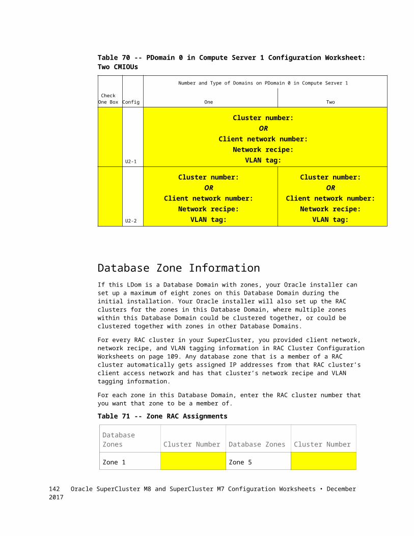
If an LDom is not a member of a RAC cluster, enter the following:o Client network number that you want to use for this LDomo Network recipe that you want to use for this LDomo VLAN tagging information, if necessary, for this LDom
Table 105 -- PDomain 0 In Compute Server 2 Configuration Worksheet: One CMIOUType of Domain on PDomain 0 on Compute Server 2
Cluster number: OR
Client network number: Network recipe:
VLAN tag:
Database Zone InformationIf this LDom is a Database Domain with zones, your Oracle installer can set up a maximum of eight zones on this Database Domain during the initial installation. Your Oracle installer will also set up the RAC clusters for the zones in this Database Domain, where multiple zones within this Database Domain could be clustered together, or could be clustered together with zones in other Database Domains.
For every RAC cluster in your SuperCluster, you provided client network, network recipe, and VLAN tagging information in RAC Cluster Configuration Worksheets on page 88. Any database zone that is a member of a RAC cluster automatically gets assigned IP addresses from that RAC cluster’s client access network and has that cluster’s network recipe and VLAN tagging information.
For each zone in this Database Domain, enter the RAC cluster number that you want that zone to be a member of.
Table 106 -- Zone RAC Assignments
Database Zones Cluster Number Database Zones Cluster Number
Zone 1 Zone 5
Zone 2 Zone 6
Zone 3 Zone 7
Zone 4 Zone 8
What’s Next If the second PDomain (PDomain 1) in compute server 2 is populated with
CMIOUs, go to PDomain 1 on Compute Server 2: Configuration Worksheets on page 154 to provide LDom configuration information and
142 Oracle SuperCluster M8 and SuperCluster M7 Configuration Worksheets • December 2017

CPU and memory resource allocation information for PDomain 1 in compute server 2.
If the second PDomain in compute server 2 is not populated, go to Completing the General Configuration Worksheets on page 169.
PDomain With Two CMIOUsEnter this configuration information if PDomain 0 in compute server 2 has two CMIOUs:
LDom Configurations on page 143 CPU Resource Allocation on page 143 Memory Resource Allocation on page 144 Client Access Network, Network Recipe, VLAN Tag and Cluster
Information on page 144 Database Zone Information on page 145
LDom ConfigurationsRead and understand the information in LDom Configurations For PDomains With Two CMIOUs on page 22 before completing the worksheets in this section.
Table 107 -- PDomain 0 in Compute Server 2 Configuration Worksheet: Two CMIOUs
Number and Type of Domains on PDomain 0 in Compute Server 2
Check One Box Config One Two
U2-1
U2-2
CPU Resource AllocationRead and understand the information in CPU Resource Allocation For PDomains With Two CMIOUs on page 32 before completing the worksheets in this section.
Table 108 -- PDomain 0 in Compute Server 2 Configuration Worksheet: Two CMIOUs
Check One Box
Config
CPU Resource Allocation for PDomain 0 in Compute Server 2Total Number of
CoresOne Two
U2-1
143
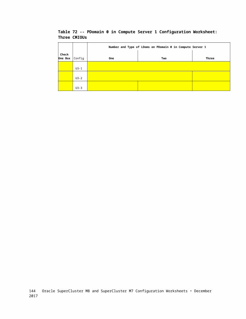
U2-2
Note - Total number of cores must be 64, unless some resources are parked.
Memory Resource AllocationRead and understand the information in Memory Resource Allocation For PDomains With Two CMIOUs on page 42 before completing the worksheets in this section.
Table 109 -- PDomain 0 in Compute Server 2 Configuration Worksheet: Two CMIOUs
Check One Box
Config
Memory Resource Allocation for PDomain 0 in Compute Server 2Total Amount of
MemoryOne Two
U2-1
U2-2
Note - Total amount of memory resources must be 1920 GB (SuperCluster M8) or 960 GB (SuperCluster M7), unless some resources are parked.
Client Access Network, Network Recipe, VLAN Tag and Cluster InformationRead and understand the information in Understanding Client Access Network, Network Recipe, VLAN Tag, and RAC Cluster Options on page 47 before completing the worksheets in this section.
For every RAC cluster in your SuperCluster, you provided client network, network recipe, and VLAN tagging information in RAC Cluster Configuration Worksheets on page 88. Any Database Domain or database zone that is a member of a RAC cluster automatically gets assigned IP addresses from that RAC cluster’s client access network and has that cluster’s network recipe and VLAN tagging information. Therefore:
If an LDom is a member of a RAC cluster, enter that RAC cluster number here. It will automatically get IP addresses from that RAC cluster’s client access network and will use that cluster’s VLAN tagging information.
If an LDom is not a member of a RAC cluster, enter the following:o Client network number that you want to use for this LDomo Network recipe that you want to use for this LDomo VLAN tagging information, if necessary, for this LDom
144 Oracle SuperCluster M8 and SuperCluster M7 Configuration Worksheets • December 2017

Table 110 -- PDomain 0 in Compute Server 2 Configuration Worksheet: Two CMIOUs
Number and Type of Domains on PDomain 0 in Compute Server 2
Check One Box Config One Two
U2-1
Cluster number: OR
Client network number: Network recipe:
VLAN tag:
U2-2
Cluster number: OR
Client network number: Network recipe:
VLAN tag:
Cluster number: OR
Client network number: Network recipe:
VLAN tag:
Database Zone InformationIf this LDom is a Database Domain with zones, your Oracle installer can set up a maximum of eight zones on this Database Domain during the initial installation. Your Oracle installer will also set up the RAC clusters for the zones in this Database Domain, where multiple zones within this Database Domain could be clustered together, or could be clustered together with zones in other Database Domains.
For every RAC cluster in your SuperCluster, you provided client network, network recipe, and VLAN tagging information in RAC Cluster Configuration Worksheets on page 88. Any database zone that is a member of a RAC cluster automatically gets assigned IP addresses from that RAC cluster’s client access network and has that cluster’s network recipe and VLAN tagging information.
For each zone in this Database Domain, enter the RAC cluster number that you want that zone to be a member of.
Table 111 -- Zone RAC Assignments
Database Zones Cluster Number Database Zones Cluster Number
Zone 1 Zone 5
Zone 2 Zone 6
Zone 3 Zone 7
Zone 4 Zone 8
145

What’s Next If the second PDomain (PDomain 1) in compute server 2 is populated with
CMIOUs, go to PDomain 1 on Compute Server 2: Configuration Worksheets on page 154 to provide LDom configuration information and CPU and memory resource allocation information for PDomain 1 in compute server 2.
If the second PDomain in compute server 2 is not populated, go to Completing the General Configuration Worksheets on page 169.
PDomain With Three CMIOUsEnter this configuration information if PDomain 0 in compute server 2 has three CMIOUs:
LDom Configurations on page 146 CPU Resource Allocation on page 147 Memory Resource Allocation on page 147 Client Access Network, Network Recipe, VLAN Tag and Cluster
Information on page 148 Database Zone Information on page 149
LDom ConfigurationsRead and understand the information in LDom Configurations For PDomains With Three CMIOUs on page 24 before completing the worksheets in this section.
Table 112 -- PDomain 0 in Compute Server 2 Configuration Worksheet: Three CMIOUs
Number and Type of LDoms on PDomain 0 in Compute Server 2
Check One Box Config One Two Three
U3-1
U3-2
U3-3
146 Oracle SuperCluster M8 and SuperCluster M7 Configuration Worksheets • December 2017

CPU Resource AllocationRead and understand the information in CPU Resource Allocation For PDomains With Three CMIOUs on page 33 before completing the worksheets in this section.
Table 113 -- PDomain 0 in Compute Server 2 Configuration Worksheet: Three CMIOUs
CPU Resource Allocation for PDomain 0 in Compute Server 2
Check One Box Config One Two Three
Total Number of
Cores
U3-1
U3-2
U3-3
Note - Total number of cores must be 96, unless some resources are parked.
Memory Resource AllocationRead and understand the information in Memory Resource Allocation For PDomains With Three CMIOUs on page 43 before completing the worksheets in this section.
Table 114 -- PDomain 0 in Compute Server 2 Configuration Worksheet: Three CMIOUs
Memory Resource Allocation for PDomain 0 in Compute Server 2
Check One Box Config One Two Three
Total Amount
of Memory
U3-1
U3-2
U3-3
Note - Total amount of memory must be 3840 GB (SuperCluster M8) or 1440 GB (SuperCluster M7), unless some resources are parked.
147

Client Access Network, Network Recipe, VLAN Tag and Cluster InformationRead and understand the information in Understanding Client Access Network, Network Recipe, VLAN Tag, and RAC Cluster Options on page 47 before completing the worksheets in this section.
For every RAC cluster in your SuperCluster, you provided client network, network recipe, and VLAN tagging information in RAC Cluster Configuration Worksheets on page 88. Any Database Domain or database zone that is a member of a RAC cluster automatically gets assigned IP addresses from that RAC cluster’s client access network and has that cluster’s network recipe and VLAN tagging information. Therefore:
If an LDom is a member of a RAC cluster, enter that RAC cluster number here. It will automatically get IP addresses from that RAC cluster’s client access network and will use that cluster’s network recipe and VLAN tagging information.
If an LDom is not a member of a RAC cluster, enter the following:o Client network number that you want to use for this LDomo Network recipe that you want to use for this LDomo VLAN tagging information, if necessary, for this LDom
Table 115 -- PDomain 0 in Compute Server 2 Configuration Worksheet: Three CMIOUs
Number and Type of LDoms on PDomain 0 in Compute Server 2
Check One Box Config One Two Three
U3-1
Cluster number: OR
Client network number: Network recipe:
VLAN tag:
U3-2
Cluster number: OR
Client network number: Network recipe:
VLAN tag:
Cluster number: OR
Client network number:
Network recipe: VLAN tag:
U3-3
Cluster number: OR
Client network number:
Network recipe: VLAN tag:
Cluster number: OR
Client network number:
Network recipe: VLAN tag:
Cluster number: OR
Client network number:
Network recipe: VLAN tag:
148 Oracle SuperCluster M8 and SuperCluster M7 Configuration Worksheets • December 2017

Database Zone InformationIf this LDom is a Database Domain with zones, your Oracle installer can set up a maximum of eight zones on this Database Domain during the initial installation. Your Oracle installer will also set up the RAC clusters for the zones in this Database Domain, where multiple zones within this Database Domain could be clustered together, or could be clustered together with zones in other Database Domains.
For every RAC cluster in your SuperCluster, you provided client network, network recipe, and VLAN tagging information in RAC Cluster Configuration Worksheets on page 88. Any database zone that is a member of a RAC cluster automatically gets assigned IP addresses from that RAC cluster’s client access network and has that cluster’s network recipe and VLAN tagging information.
For each zone in this Database Domain, enter the RAC cluster number that you want that zone to be a member of.
Table 116 -- Zone RAC Assignments
Database Zones Cluster Number Database Zones Cluster Number
Zone 1 Zone 5
Zone 2 Zone 6
Zone 3 Zone 7
Zone 4 Zone 8
What’s Next If the second PDomain (PDomain 1) in compute server 2 is populated with
CMIOUs, go to PDomain 1 on Compute Server 2: Configuration Worksheets on page 154 to provide LDom configuration information and CPU and memory resource allocation information for PDomain 1 in compute server 2.
If the second PDomain in compute server 2 is not populated, go to Completing the General Configuration Worksheets on page 169.
PDomain With Four CMIOUsEnter this configuration information if PDomain 0 in compute server 2 has four CMIOUs:
LDom Configurations on page 150 CPU Resource Allocation on page 150 Memory Resource Allocation on page 151 Client Access Network, Network Recipe, VLAN Tag and Cluster
149

Information on page 151 Database Zone Information on page 152
LDom ConfigurationsRead and understand the information in LDom Configurations For PDomains With Four CMIOUs on page 26 before completing the worksheets in this section.
Table 117 -- PDomain 0 in Compute Server 2 Configuration Worksheet: Four CMIOUs
Number and Type of Domains on PDomain 0 in Compute Server 2
Check One Box Config One Two Three Four
U4-1
U4-2
U4-3
U4-4
CPU Resource AllocationRead and understand the information in CPU Resource Allocation For PDomains With Four CMIOUs on page 35 before completing the worksheets in this section.
Table 118 -- PDomain 0 in Compute Server 2 Configuration Worksheet: Four CMIOUs
CPU Resource Allocation for PDomain 0 in Compute Server 2
Check One Box Config One Two Three Four
Total Number of
Cores
U4-1
U4-2
U4-3
U4-4
Note - Total number of cores must be 128, unless some resources are parked.
150 Oracle SuperCluster M8 and SuperCluster M7 Configuration Worksheets • December 2017

Memory Resource Allocation Read and understand the information in Memory Resource Allocation For PDomains With Four CMIOUs on page 44 before completing the worksheets in this section.
Table 119 -- PDomain 0 in Compute Server 2 Configuration Worksheet: Four CMIOUs
Memory Resource Allocation for PDomain 0 in Compute Server 2
Check One Box Config One Two Three Four
Total Amount of Memory
U4-1
U4-2
U4-3
U4-4
Note - Total amount of memory resources must be 3840 (SuperCluster M8) or 1980 GB (SuperCluster M7), unless some resources are parked.
Client Access Network, Network Recipe, VLAN Tag and Cluster InformationRead and understand the information in Understanding Client Access Network, Network Recipe, VLAN Tag, and RAC Cluster Options on page 47 before completing the worksheets in this section.
For every RAC cluster in your SuperCluster, you provided client network, network recipe, and VLAN tagging information in RAC Cluster Configuration Worksheets on page 88. Any Database Domain or database zone that is a member of a RAC cluster automatically gets assigned IP addresses from that RAC cluster’s client access network and has that cluster’s network recipe and VLAN tagging information. Therefore:
If an LDom is a member of a RAC cluster, enter that RAC cluster number here. It will automatically get IP addresses from that RAC cluster’s client access network and will use that cluster’s network recipe and VLAN tagging information.
If an LDom is not a member of a RAC cluster, enter the following:o Client network number that you want to use for this LDomo Network recipe that you want to use for this LDomo VLAN tagging information, if necessary, for this LDom
151

Table 120 -- PDomain 0 in Compute Server 2 Configuration Worksheet: Four CMIOUs
Number and Type of Domains on PDomain 0 in Compute Server 2
Check One Box Config One Two Three Four
U4-1
Cluster number: OR
Client network number: Network recipe:
VLAN tag:
U4-2
Cluster number: OR
Client network number: Network recipe:
VLAN tag:
Cluster number: OR
Client network number: Network recipe:
VLAN tag:
U4-3
Cluster number: OR
Client network number: Network recipe:
VLAN tag:
Cluster number: OR
Client network number:
Network recipe: VLAN tag:
Cluster number:
OR Client
network number: Network recipe:
VLAN tag:
U4-4
Cluster number: OR
Client network number:
Network recipe: VLAN tag:
Cluster number: OR
Client network number:
Network recipe: VLAN tag:
Cluster number: OR
Client network number:
Network recipe: VLAN tag:
Cluster number:
OR Client
network number: Network recipe:
VLAN tag:
Database Zone InformationIf this LDom is a Database Domain with zones, your Oracle installer can set up a maximum of eight zones on this Database Domain during the initial installation. Your Oracle installer will also set up the RAC clusters for the zones in this Database Domain, where multiple zones within this Database Domain could be clustered together, or could be clustered together with zones in other Database Domains.
For every RAC cluster in your SuperCluster, you provided client network, network recipe, and VLAN tagging information in RAC Cluster Configuration Worksheets on
152 Oracle SuperCluster M8 and SuperCluster M7 Configuration Worksheets • December 2017

page 88. Any database zone that is a member of a RAC cluster automatically gets assigned IP addresses from that RAC cluster’s client access network and has that cluster’s network recipe and VLAN tagging information.
For each zone in this Database Domain, enter the RAC cluster number that you want that zone to be a member of.
Table 121 -- Zone RAC Assignments
Database Zones Cluster Number Database Zones Cluster Number
Zone 1 Zone 5
Zone 2 Zone 6
Zone 3 Zone 7
Zone 4 Zone 8
What’s Next If the second PDomain (PDomain 1) in compute server 2 is populated with
CMIOUs, go to PDomain 1 on Compute Server 2: Configuration Worksheets on page 154 to provide LDom configuration information and CPU and memory resource allocation information for PDomain 1 in compute server 2.
If the second PDomain in compute server 2 is not populated, go to Completing the General Configuration Worksheets on page 169.
153

Chapter
1PDomain 1 on Compute Server 2:
Configuration WorksheetsComplete the worksheets in this chapter to provide this information for PDomain 1 in compute server 2:
Number of LDoms in this PDomain Type of LDoms in this PDomain:
Application Domain running the Oracle Solaris 11 OS (dedicated domain)
Database Domain (dedicated domain), with or without zones12
Root Domain, with some I/O Domains set up at the initial installation12
Note – Only Database Domains that are dedicated domains can host database zones. Database I/O Domains cannot host database zones.
Note – Refer to the Oracle SuperCluster M8 and SuperCluster M7 Overview Guide for more detailed information on the different configurations available.
Amount of CPU resources that you want to allocate to each LDom in this PDomain
Amount of memory resources that you want allocated to each LDom in this PDomain
Either of the following for each LDom in this PDomain: o Which RAC cluster that you want for each Database Domain or
database zone, with that RAC cluster’s client network, network recipe and VLAN tagging configurations, or
o Specific client network, network recipe and VLAN tagging configurations for each non-RAC cluster LDom
12 See Oracle Setup of Database Zones and I/O Domains Overview on page 20 for more information on the maximum number of database zones and I/O Domains that can be set up by your Oracle installer.154 Oracle SuperCluster M8 and SuperCluster M7 Configuration Worksheets • December 2017

Enter the configuration information for PDomain 1 on compute server 2 in these tables, depending on the number of CMIOUs that you have in this PDomain:
Check One Box PDomain 1 on Compute Server 2 Configuration
PDomain With One CMIOU on page 155
PDomain With Two CMIOUs on page 158PDomain With Three CMIOUs on page 161PDomain With Four CMIOUs on page 164
PDomain With One CMIOUEnter this configuration information if PDomain 1 in compute server 2 has one CMIOU:
LDom Configurations on page 155 CPU Resource Allocation on page 156 Memory Resource Allocation on page 156 Client Access Network, Network Recipe, VLAN Tag and Cluster
Information on page 156 Database Zone Information on page 157
LDom ConfigurationsRead and understand the information in LDom Configurations For PDomains With One CMIOU on page 22 before completing the worksheets in this section.
Table 122 -- PDomain 1 In Compute Server 2 Configuration Worksheet: One CMIOUType of Domain on PDomain 1 on Compute Server 2
155

CPU Resource AllocationRead and understand the information in CPU Resource Allocation For PDomains With One CMIOU on page 31 before completing the worksheets in this section.
Table 123 -- PDomain 1 In Compute Server 2 Configuration Worksheet: One CMIOUCPU Resource Allocation for PDomain 1 in Compute
Server 2Total Number of Cores
Note - Total number of cores must be 32, unless some resources are parked.
Memory Resource AllocationRead and understand the information in Memory Resource Allocation For PDomains With One CMIOU on page 41 before completing the worksheets in this section.
Table 124 -- PDomain 1 In Compute Server 2 Configuration Worksheet: One CMIOUMemory Resource Allocation for PDomain 1 in Compute Server 2 Total Amount of Memory
Note - Total amount of memory resources must be 960 GB (SuperCluster M8) or 480 GB (SuperCluster M7), unless some
resources are parked.
Client Access Network, Network Recipe, VLAN Tag and Cluster InformationRead and understand the information in Understanding Client Access Network, Network Recipe, VLAN Tag, and RAC Cluster Options on page 47 before completing the worksheets in this section.
For every RAC cluster in your SuperCluster, you provided client network, network recipe, and VLAN tagging information in RAC Cluster Configuration Worksheets on page 88. Any Database Domain or database zone that is a member of a RAC cluster automatically gets assigned IP addresses from that RAC cluster’s client access network and has that cluster’s network recipe and VLAN tagging information. Therefore:
If an LDom is a member of a RAC cluster, enter that RAC cluster number here. It will automatically get IP addresses from that RAC cluster’s client access network and will use that cluster’s network recipe and VLAN tagging information.
156 Oracle SuperCluster M8 and SuperCluster M7 Configuration Worksheets • December 2017

If an LDom is not a member of a RAC cluster, enter the following:o Client network number that you want to use for this LDomo Network recipe that you want to use for this LDomo VLAN tagging information, if necessary, for this LDom
Table 125 -- PDomain 1 In Compute Server 2 Configuration Worksheet: One CMIOUType of Domain on PDomain 1 on Compute Server 2
Cluster number: OR
Client network number: Network recipe:
VLAN tag:
Database Zone InformationIf this LDom is a Database Domain with zones, your Oracle installer can set up a maximum of eight zones on this Database Domain during the initial installation. Your Oracle installer will also set up the RAC clusters for the zones in this Database Domain, where multiple zones within this Database Domain could be clustered together, or could be clustered together with zones in other Database Domains.
For every RAC cluster in your SuperCluster, you provided client network, network recipe, and VLAN tagging information in RAC Cluster Configuration Worksheets on page 88. Any database zone that is a member of a RAC cluster automatically gets assigned IP addresses from that RAC cluster’s client access network and has that cluster’s network recipe and VLAN tagging information.
For each zone in this Database Domain, enter the RAC cluster number that you want that zone to be a member of.
Table 126 -- Zone RAC Assignments
Database Zones Cluster Number Database Zones Cluster Number
Zone 1 Zone 5
Zone 2 Zone 6
Zone 3 Zone 7
Zone 4 Zone 8
What’s NextGo to Completing the General Configuration Worksheets on page 169.
157

PDomain With Two CMIOUsEnter this configuration information if PDomain 1 in compute server 2 has two CMIOUs:
LDom Configurations on page 158 CPU Resource Allocation on page 158 Memory Resource Allocation on page 159 Client Access Network, Network Recipe, VLAN Tag and Cluster
Information on page 159 Database Zone Information on page 160
LDom ConfigurationsRead and understand the information in LDom Configurations For PDomains With Two CMIOUs on page 22 before completing the worksheets in this section.
Table 127 -- PDomain 1 In Compute Server 2 Configuration Worksheet: Two CMIOUs
Number and Type of Domains on PDomain 1 in Compute Server 2
Check One Box Config One Two
U2-1
U2-2
CPU Resource AllocationRead and understand the information in CPU Resource Allocation For PDomains With Two CMIOUs on page 32 before completing the worksheets in this section.
Table 128 -- PDomain 1 In Compute Server 2 Configuration Worksheet: Two CMIOUs
Check One Box
Config
CPU Resource Allocation for PDomain 1 in Compute Server 2Total Number of
CoresOne Two
U2-1
U2-2
Note - Total number of cores must be 64, unless some resources are parked.
158 Oracle SuperCluster M8 and SuperCluster M7 Configuration Worksheets • December 2017

Memory Resource AllocationRead and understand the information in Memory Resource Allocation For PDomains With Two CMIOUs on page 42 before completing the worksheets in this section.
Table 129 -- PDomain 1 In Compute Server 2 Configuration Worksheet: Two CMIOUs
Check One Box
Config
Memory Resource Allocation for PDomain 1 in Compute Server 2Total Amount of
MemoryOne Two
U2-1
U2-2
Note - Total amount of memory resources must be 1920 GB (SuperCluster M8) or 960 GB (SuperCluster M7), unless some resources are parked.
Client Access Network, Network Recipe, VLAN Tag and Cluster InformationRead and understand the information in Understanding Client Access Network, Network Recipe, VLAN Tag, and RAC Cluster Options on page 47 before completing the worksheets in this section.
For every RAC cluster in your SuperCluster, you provided client network, network recipe, and VLAN tagging information in RAC Cluster Configuration Worksheets on page 88. Any Database Domain or database zone that is a member of a RAC cluster automatically gets assigned IP addresses from that RAC cluster’s client access network and has that cluster’s network recipe and VLAN tagging information. Therefore:
If an LDom is a member of a RAC cluster, enter that RAC cluster number here. It will automatically get IP addresses from that RAC cluster’s client access network and will use that cluster’s network recipe and VLAN tagging information.
If an LDom is not a member of a RAC cluster, enter the following:o Client network number that you want to use for this LDomo Network recipe that you want to use for this LDomo VLAN tagging information, if necessary, for this LDom
159

Table 130 -- PDomain 1 in Compute Server 2 Configuration Worksheet: Two CMIOUs
Number and Type of Domains on PDomain 1 in Compute Server 2
Check One Box Config One Two
U2-1
Cluster number: OR
Client network number: Network recipe:
VLAN tag:
U2-2
Cluster number: OR
Client network number: Network recipe:
VLAN tag:
Cluster number: OR
Client network number: Network recipe:
VLAN tag:
Database Zone InformationIf this LDom is a Database Domain with zones, your Oracle installer can set up a maximum of eight zones on this Database Domain during the initial installation. Your Oracle installer will also set up the RAC clusters for the zones in this Database Domain, where multiple zones within this Database Domain could be clustered together, or could be clustered together with zones in other Database Domains.
For every RAC cluster in your SuperCluster, you provided client network, network recipe, and VLAN tagging information in RAC Cluster Configuration Worksheets on page 88. Any database zone that is a member of a RAC cluster automatically gets assigned IP addresses from that RAC cluster’s client access network and has that cluster’s network recipe and VLAN tagging information.
For each zone in this Database Domain, enter the RAC cluster number that you want that zone to be a member of.
Table 131 -- Zone RAC Assignments
Database Zones Cluster Number Database Zones Cluster Number
Zone 1 Zone 5
Zone 2 Zone 6
Zone 3 Zone 7
Zone 4 Zone 8
160 Oracle SuperCluster M8 and SuperCluster M7 Configuration Worksheets • December 2017

What’s NextGo to Completing the General Configuration Worksheets on page 169.
PDomain With Three CMIOUsEnter this configuration information if PDomain 1 in compute server 2 has three CMIOUs:
LDom Configurations on page 161 CPU Resource Allocation on page 162 Memory Resource Allocation on page 162 Client Access Network, Network Recipe, VLAN Tag and Cluster
Information on page 163 Database Zone Information on page 164
LDom ConfigurationsRead and understand the information in LDom Configurations For PDomains With Three CMIOUs on page 24 before completing the worksheets in this section.
Table 132 -- PDomain 1 In Compute Server 2 Configuration Worksheet: Three CMIOUs
Number and Type of LDoms on PDomain 1 in Compute Server 2
Check One Box Config One Two Three
U3-1
U3-2
U3-3
161

CPU Resource AllocationRead and understand the information in CPU Resource Allocation For PDomains With Three CMIOUs on page 33 before completing the worksheets in this section.
Table 133 -- PDomain 1 In Compute Server 2 Configuration Worksheet: Three CMIOUs
CPU Resource Allocation for PDomain 1 in Compute Server 2
Check One Box Config One Two Three
Total Number of Cores
U3-1
U3-2
U3-3
Note - Total number of cores must be 96, unless some resources are parked.
Memory Resource AllocationRead and understand the information in Memory Resource Allocation For PDomains With Three CMIOUs on page 43 before completing the worksheets in this section.
Table 134 -- PDomain 1 In Compute Server 2 Configuration Worksheet: Three CMIOUs
Memory Resource Allocation for PDomain 1 in Compute Server 2
Check One Box Config One Two Three
Total Amount
of Memory
U3-1
U3-2
U3-3
Note - Total amount of memory must be 2880 GB (SuperCluster M8) or 1440 GB (SuperCluster M7), unless some resources are parked.
162 Oracle SuperCluster M8 and SuperCluster M7 Configuration Worksheets • December 2017

Client Access Network, Network Recipe, VLAN Tag and Cluster InformationRead and understand the information in Understanding Client Access Network, Network Recipe, VLAN Tag, and RAC Cluster Options on page 47 before completing the worksheets in this section.
For every RAC cluster in your SuperCluster, you provided client network, network recipe, and VLAN tagging information in RAC Cluster Configuration Worksheets on page 88. Any Database Domain or database zone that is a member of a RAC cluster automatically gets assigned IP addresses from that RAC cluster’s client access network and has that cluster’s network recipe and VLAN tagging information. Therefore:
If an LDom is a member of a RAC cluster, enter that RAC cluster number here. It will automatically get IP addresses from that RAC cluster’s client access network and will use that cluster’s network recipe and VLAN tagging information.
If an LDom is not a member of a RAC cluster, enter the following:o Client network number that you want to use for this LDomo Network recipe that you want to use for this LDomo VLAN tagging information, if necessary, for this LDom
Table 135 -- PDomain 1 in Compute Server 2 Configuration Worksheet: Three CMIOUs
Number and Type of LDoms on PDomain 1 in Compute Server 2
Check One Box Config One Two Three
U3-1
Cluster number: OR
Client network number: Network recipe:
VLAN tag:
U3-2
Cluster number: OR
Client network number: Network recipe:
VLAN tag:
Cluster number: OR
Client network number:
Network recipe: VLAN tag:
U3-3
Cluster number: OR
Client network number:
Network recipe: VLAN tag:
Cluster number: OR
Client network number:
Network recipe: VLAN tag:
Cluster number: OR
Client network number:
Network recipe: VLAN tag:
163

Database Zone InformationIf this LDom is a Database Domain with zones, your Oracle installer can set up a maximum of eight zones on this Database Domain during the initial installation. Your Oracle installer will also set up the RAC clusters for the zones in this Database Domain, where multiple zones within this Database Domain could be clustered together, or could be clustered together with zones in other Database Domains.
For every RAC cluster in your SuperCluster, you provided client network, network recipe, and VLAN tagging information in RAC Cluster Configuration Worksheets on page 88. Any database zone that is a member of a RAC cluster automatically gets assigned IP addresses from that RAC cluster’s client access network and has that cluster’s network recipe and VLAN tagging information.
For each zone in this Database Domain, enter the RAC cluster number that you want that zone to be a member of.
Table 136 -- Zone RAC Assignments
Database Zones Cluster Number Database Zones Cluster Number
Zone 1 Zone 5
Zone 2 Zone 6
Zone 3 Zone 7
Zone 4 Zone 8
What’s NextGo to Completing the General Configuration Worksheets on page 169.
PDomain With Four CMIOUsEnter this configuration information if PDomain 1 in compute server 2 has four CMIOUs:
LDom Configurations on page 165 CPU Resource Allocation on page 165 Memory Resource Allocation on page 166 Client Access Network, Network Recipe, VLAN Tag and Cluster
Information on page 166 Database Zone Information on page 167
164 Oracle SuperCluster M8 and SuperCluster M7 Configuration Worksheets • December 2017

LDom ConfigurationsRead and understand the information in LDom Configurations For PDomains With Four CMIOUs on page 26 before completing the worksheets in this section.
Table 137 -- PDomain 1 In Compute Server 2 Configuration Worksheet: Four CMIOUs
Number and Type of Domains on PDomain 0 in Compute Server 1
Check One Box Config One Two Three Four
U4-1
U4-2
U4-3
U4-4
CPU Resource AllocationRead and understand the information in CPU Resource Allocation For PDomains With Four CMIOUs on page 35 before completing the worksheets in this section.
Table 138 -- PDomain 1 In Compute Server 2 Configuration Worksheet: Four CMIOUs
CPU Resource Allocation for PDomain 0 in Compute Server 1
Check One Box Config One Two Three Four
Total Number of
Cores
U4-1
U4-2
U4-3
U4-4
Note - Total number of cores must be 128, unless some resources are parked.
165

Memory Resource AllocationRead and understand the information in Memory Resource Allocation For PDomains With Four CMIOUs on page 44 before completing the worksheets in this section.
Table 139 -- PDomain 1 In Compute Server 2 Configuration Worksheet: Four CMIOUs
Memory Resource Allocation for PDomain 0 in Compute Server 1
Check One Box Config One Two Three Four
Total Amount of Memory
U4-1
U4-2
U4-3
U4-4
Note - Total amount of memory resources must be 3840 (SuperCluster M8) or 1980 GB (SuperCluster M7), unless some resources are parked.
Client Access Network, Network Recipe, VLAN Tag and Cluster InformationRead and understand the information in Understanding Client Access Network, Network Recipe, VLAN Tag, and RAC Cluster Options on page 47 before completing the worksheets in this section.
For every RAC cluster in your SuperCluster, you provided client network, network recipe, and VLAN tagging information in RAC Cluster Configuration Worksheets on page 88. Any Database Domain or database zone that is a member of a RAC cluster automatically gets assigned IP addresses from that RAC cluster’s client access network and has that cluster’s network recipe and VLAN tagging information. Therefore:
If an LDom is a member of a RAC cluster, enter that RAC cluster number here. It will automatically get IP addresses from that RAC cluster’s client access network and will use that cluster’s network recipe and VLAN tagging information.
If an LDom is not a member of a RAC cluster, enter the following:o Client network number that you want to use for this LDomo Network recipe that you want to use for this LDomo VLAN tagging information, if necessary, for this LDom
166 Oracle SuperCluster M8 and SuperCluster M7 Configuration Worksheets • December 2017

Table 140 -- PDomain 1 in Compute Server 2 Configuration Worksheet: Four CMIOUs
Number and Type of Domains on PDomain 1 in Compute Server 2
Check One Box Config One Two Three Four
U4-1
Cluster number: OR
Client network number: Network recipe:
VLAN tag:
U4-2
Cluster number: OR
Client network number: Network recipe:
VLAN tag:
Cluster number: OR
Client network number: Network recipe:
VLAN tag:
U4-3
Cluster number: OR
Client network number: Network recipe:
VLAN tag:
Cluster number: OR
Client network number:
Network recipe: VLAN tag:
Cluster number:
OR Client
network number: Network recipe:
VLAN tag:
U4-4
Cluster number: OR
Client network number:
Network recipe: VLAN tag:
Cluster number: OR
Client network number:
Network recipe: VLAN tag:
Cluster number: OR
Client network number:
Network recipe: VLAN tag:
Cluster number:
OR Client
network number: Network recipe:
VLAN tag:
Database Zone InformationIf this LDom is a Database Domain with zones, your Oracle installer can set up a maximum of eight zones on this Database Domain during the initial installation. Your Oracle installer will also set up the RAC clusters for the zones in this Database Domain, where multiple zones within this Database Domain could be clustered together, or could be clustered together with zones in other Database Domains.
For every RAC cluster in your SuperCluster, you provided client network, network recipe, and VLAN tagging information in RAC Cluster Configuration Worksheets on page 88. Any database zone that is a member of a RAC cluster automatically gets
167

assigned IP addresses from that RAC cluster’s client access network and has that cluster’s network recipe and VLAN tagging information.
For each zone in this Database Domain, enter the RAC cluster number that you want that zone to be a member of.
Table 141 -- Zone RAC Assignments
Database Zones Cluster Number Database Zones Cluster Number
Zone 1 Zone 5
Zone 2 Zone 6
Zone 3 Zone 7
Zone 4 Zone 8
What’s NextGo to Completing the General Configuration Worksheets on page 169.
168 Oracle SuperCluster M8 and SuperCluster M7 Configuration Worksheets • December 2017
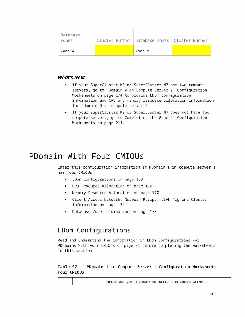
Chapter
1Completing the General Configuration
WorksheetsComplete the configuration worksheets in this chapter to provide general configuration information for your SuperCluster M8 or SuperCluster M7.
General SuperCluster Configuration Information
When filling out the worksheets in this chapter, note the following items: SuperCluster ships with the Oracle Solaris Operating System (Oracle
Solaris OS) installed on the compute servers. The name (prefix) of SuperCluster s used to generate host names for
network interfaces for the components and logical domains in the system. The name of SuperCluster is completely user-definable, but because the name for SuperCluster is used to generate the host names for the components listed above, you should use six characters or fewer for the name of SuperCluster. You enter the name of SuperCluster in Customer Details Configuration Worksheet on page 176.
Note – It is possible to create a name for SuperCluster that is longer than six characters. However, you might get the following error message: Maximum combined length of cell short hostname + diskgroup name is too long - max length is 23 characters. The installer can manually shorten the disk group name to accommodate the combined maximum length of 23 characters in this case.
169

For certain components, the company network domain name, such as example.com, is also used to generate host names for network interfaces for those components. The company network domain name is completely user-definable. The company network domain name is defined in Operating System Configuration Worksheet on page 178 in this document.
The backup method information is used to size the ASM disk groups created during installation. The amount of usable disk space varies depending on the backup method. The backup methods are as follows:
Backups internal to SuperCluster mean database backups are created only on disk in the Fast Recovery Area (FRA). In addition to the database backups, there are other objects such as Archived Redo Logs and Flashback Log Files stored in the FRA. The division of disk space between the DATA disk group and the RECO disk group (the FRA) is 40% and 60%, respectively.
Backups external to SuperCluster mean database backups are created on disk or tape media that is external to that currently deployed on SuperCluster systems, and not on existing Exadata Storage Servers. If you are performing backups to disk storage external to SuperCluster, such as to additional dedicated storage servers, an NFS server, virtual tape library or tape library, then do not reserve additional space in the RECO disk group. When choosing this option, the FRA internal to SuperCluster contains objects such as archived redo log files and flashback log files. The division of disk space between the DATA disk group and the RECO disk group (the FRA) is 80% and 20%, respectively.
A valid time zone name is required for SuperCluster installation. Time zone data provided with the system comes from the zoneinfo database. A valid time zone name is suitable as a value for the TZ environment variable consisting of form area/location. For example, a valid entry is America/New_York. Invalid entries are EST, EDT, UTC-5, and UTC-4. For a list of time zone names, refer to the zone.tab file in the zoneinfo database available in the public domain at ftp://elsie.nci.nih.gov/pub/.
Use high redundancy disk groups for mission critical applications. The location of the backup files depends on the backup method. To reserve more space for the DATA disk group, choose external backups. This is especially important when the RECO disk group is high redundancy. This table shows the backup options and settings.
170 Oracle SuperCluster M8 and SuperCluster M7 Configuration Worksheets • December 2017

Description Redundancy Level for DATA Disk Group
Redundancy Level for RECO Disk Group
High Redundancy for ALLBoth the DATA disk group and RECO disk group are configured with Oracle ASM high redundancy. The DATA disk group contains data files, temporary files, online redo logs, and a control file. The RECO disk group contains archive logs, and flashback log files.
High High
High Redundancy for DATAThe DATA disk group is configured with OracleASM high redundancy, and the RECO disk group is configured with Oracle ASM normal redundancy. The DATA disk group contains data files, online redo logs, and a control file. The RECO disk group contains archive logs, temporary files, and flashback log files.
High Normal
High Redundancy for Log and RECOThe DATA disk group is configured with OracleASM normal redundancy, and the RECO disk group is configured with Oracle ASM high redundancy. The DATA disk group contains the data files and temporary files. The RECO disk group contains online redo logs, a control file, archive logs, and flashback log files.
Normal High
Normal RedundancyThe DATA Disk Group and RECO disk group are configured with Oracle ASM normal redundancy. The DATA disk group contains data files, temporary files, online redo logs, and a control file. The RECO disk group contains online redo logs, archive logs, and flashback log files.
Normal Normal
Exadata Storage Server Information for SuperCluster M8
Oracle Exadata X7-2L Storage Servers are supported in SuperCluster M8. Each storage server includes either Extreme Flash (EF) or High Capacity (HC) storage.These are the characteristics of the Exadata Storage Servers:
171

SuperCluster M8 comes with a minimum of three storage servers.
o In a single-server configuration, up to eight additional storage servers can be added to the system, for a total of eleven storage servers in the system.
o In a dual-server configuration, up to three additional storage servers can be added to the system, for a total of six storage servers in the system.
The expansion rack is available as a quarter rack, with four storage servers. You can increase the number of storage servers in the expansion rack up to a maximum of 18 storage servers.
See Oracle Exadata Storage Server Software User's Guide for information about maximum availability. Also see these tables for more information on storage capacities based on the level of redundancy that you choose. These tables list the storage capacities for a single storage server. To determine the system’s total storage server capacity, multiply the single storage server capacity with the total number of storage servers in the system.
Table 142 -- X7-2L Single Storage Server Capacities
Capacity Type 8 x 6.4-TB Extreme Flash Drives
12 x 10-TB High Capacity Drives
Raw PCI flash capacity1351.2 TB 120 TB
Usable mirrored capacity (ASM normal redundancy)
20 TB 50 TB
Usable triple mirrored capacity (ASM high redundancy)
17.2 TB 37.5 TB
Note – The tables do not include capacities of the PCIe flash cards that are part of the HC storage server infrastructure.
Exadata Storage Server Information for SuperCluster M7
Oracle Exadata X5-2L Storage Servers and Oracle Exadata X6-2L Storage Servers are supported in SuperCluster M7. You can install a combination of storage server models in a system. Each storage server includes either Extreme Flash (EF) or High Capacity (HC) storage.These are the characteristics of the Exadata Storage Servers:
SuperCluster M7 comes with a minimum of three storage servers.
13 For raw capacity, 1 GB = 1 billion bytes. Capacity calculated using normal space terminology of 1 TB = 1024 * 1024 * 1024 * 1024 bytes. Actual formatted capacity is less.172 Oracle SuperCluster M8 and SuperCluster M7 Configuration Worksheets • December 2017

o In a single-server configuration, up to eight additional storage servers can be added to the system, for a total of eleven storage servers in the system.
o In a dual-server configuration, up to three additional storage servers can be added to the system, for a total of six storage servers in the system.
The expansion rack is available as a quarter rack, with four storage servers. You can increase the number of storage servers in the expansion rack up to a maximum of 18 storage servers.
See Oracle Exadata Storage Server Software User's Guide for information about maximum availability. Also see these tables for more information on storage capacities based on the level of redundancy that you choose. These tables list the storage capacities for a single storage server. To determine the system’s total storage server capacity, multiply the single storage server capacity with the total number of storage servers in the system.
Table 143 -- X5-2L Single Storage Server Capacities
Capacity Type 8 x 1.6-TB Extreme Flash Drives
12 x 8-TB High Capacity Drives
Raw PCI flash capacity1412.8 TB 96 TB
Usable mirrored capacity (ASM normal redundancy)
5 TB 40 TB
Usable triple mirrored capacity (ASM high redundancy)
4.3 TB 30 TB
Table 144 -- X6-2L Single Storage Server Capacities
Capacity Type 8 x 3.2-TB Extreme Flash Drives
12 x 8-TB High Capacity Drives
Raw PCI flash capacity1525.6 TB 96 TB
Usable mirrored capacity (ASM normal redundancy)
10 TB 40 TB
Usable triple mirrored capacity (ASM high redundancy)
8.6 TB 30 TB
Note – The tables do not include capacities of the PCIe flash cards that are part of the HC storage server infrastructure.
14 For raw capacity, 1 GB = 1 billion bytes. Capacity calculated using normal space terminology of 1 TB = 1024 * 1024 * 1024 * 1024 bytes. Actual formatted capacity is less.15 For raw capacity, 1 GB = 1 billion bytes. Capacity calculated using normal space terminology of 1 TB = 1024 * 1024 * 1024 * 1024 bytes. Actual formatted capacity is less.
173

What’s Next Go to General Configuration Worksheets on page 175 to complete the general configuration worksheets.
174 Oracle SuperCluster M8 and SuperCluster M7 Configuration Worksheets • December 2017

Chapter
1General Configuration Worksheets
Read and understand the information in Completing the General Configuration Worksheets on page 169 before completing any worksheets in this chapter:
Customer Details Configuration Worksheet on page 176 Backup/Data Guard Ethernet Network Configuration Worksheet on page
177 Operating System Configuration Worksheet on page 178 Home and Database Configuration Worksheet on page 180 (Optional) Cell Alerting Configuration Worksheet on page 181 (Optional) Oracle Configuration Manager Configuration Worksheet on
page 183 Auto Service Request Configuration Worksheet on page 184
175

Customer Details Configuration Worksheet
Table 145 -- Customer Details Configuration Worksheet
Item Entry Description and Example
Customer Name The customer name. The name can contain any alphanumeric characters, including spaces. This field cannot be empty.
Application The application that will be used on the domains.
Region Country where SuperCluster will be installed.Example: United States
Time Zone Time zone name where SuperCluster will be installed.Example: America/Los_Angeles
Compute OS Oracle Solaris The operating system for the domains on SuperCluster. Oracle Solaris is the only valid entry for this field, even if you have Database Domains in your system.
176 Oracle SuperCluster M8 and SuperCluster M7 Configuration Worksheets • December 2017

Backup/Data Guard Ethernet Network Configuration Worksheet
Table 146 -- Backup/Data Guard Ethernet Network Configuration Worksheet
Item Entry Description and Example
Enable backup/Data Guard Network
Determine if a backup network is being used for this system. Options: Enabled or Disabled
Starting IP Address for Pool
This is the starting IP address for the IP addresses assigned to the backup network.Note - The pool should consist of consecutive IP addresses. If consecutive IP addresses are not available, then specific IP addresses can be modified during the configuration process.
Pool Size The value of this field is defined by the type of SuperCluster M8 or SuperCluster M7 (single server or dual server).
Ending IP Address for Pool
The value of this field is defined by the starting IP address and the pool size.
Subnet Mask The subnet mask for the backup network.
Gateway The gateway for the subnet. Ensure that the defined IP address is correct for the gateway.
Implement host based bonded network
This option is selected when using a bonded network. Options: Enabled or Disabled
177

Operating System Configuration Worksheet
Table 147 -- Custom Details Configuration Worksheet
Item Entry Description and Example
Domain Name The company network domain name, such as example.com. The name can contain alphanumeric characters, periods (.), and hyphens (-). The name must start with an alphanumeric character. This field cannot be empty.
DNS Servers The IP address for the domain name servers. At least one IP address must be provided.
NTP Servers The IP address for the Network Time Protocol servers. At least one IP address must be provided.
Separate Grid Infrastructure owner from Database owner
Determine if the responsibilities and privileges are separated by role.Providing system privileges for the storage tier using the SYSASM privilege instead of the SYSDBA privilege provides a clear division of responsibility between Oracle ASM administration and database administration. Role separation also helps to prevent different databases using the same storage from accidentally overwriting each other's files.Options: Selected or Unselected
Grid ASM Home OS User
The user name for the Oracle ASM owner. The default is grid. This user owns the Oracle Grid Infrastructure installation.This option is available when using role-separated authentication.
Grid ASM Home OS UserId
The identifier for the Oracle ASM owner. The default is 1000.This option is available when using role-separated authentication.
Grid ASM Home Base Location
The directory for the Oracle grid infrastructure. The default is /u01/app/grid.This option is available when using role-separated authentication.
ASM DBA Group The name for the Oracle ASM DBA group. The default is asmdba. Membership in this group enables access to the files managed by
178 Oracle SuperCluster M8 and SuperCluster M7 Configuration Worksheets • December 2017

Item Entry Description and Example
Oracle ASM.This option is available when using role-separated authentication.
ASM DBA GroupID
The identifier for the Oracle ASM DBA group. The default is 1004.This option is available when using role-separated authentication.
ASM Home Operator Group
The name for the Oracle ASM operator group. The default is asmoper.This group of operating system users has a limited set of Oracle instance administrative privileges including starting up and stopping the Oracle ASM instance.This option is available when using role-separated authentication.
ASM Home Operator GroupId
The identifier for the Oracle ASM operator group. The default is 1005.This option is available when using role-separated authentication.
ASM Home Admin Group
The name for the Oracle ASM administration group. The default is asmadmin.This group uses SQL to connect to an Oracle ASM instance as SYSASM using operating system authentication. The SYSASM privileges permit mounting and dismounting of disk groups, and other storage administration tasks. SYSASM privileges provide no access privileges on an Oracle Database instance.This option is available when using role-separated authentication.
ASM Home Admin GroupId
The identifier for the Oracle ASM administration group. The default is 1006.This option is available when using role-separated authentication.
RDBMS Home OS User
The user name for the owner of the Oracle Database installation. The default is oracle.
RDBMS Home OS UserId
The identifier for the owner of the Oracle Database installation. The default is 1001.
RDBMS Home Base Location
The directory for the Oracle Database installation. The default is /u01/app/oracle.
179
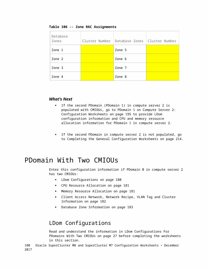
Item Entry Description and Example
RDBMS DBA Group
The name for the database administration group. The default is 1002.
RDBMS Home Operator Group
The name for the Oracle Database operator group. The default is racoper.
RDBMS Home Operator GroupId
The identifier for the Oracle Database operator group. The default is 1003.
Oinstall Group The name for the Oracle Inventory group. The default is oinstall.
Oinstall GroupId The identifier for the Oracle Inventory group. The default is 1001.
Home and Database Configuration WorksheetUse this worksheet to provide information on the home and database configuration. The disk group sizes shown in the configuration page are approximate, based on the type of SuperCluster M8 or SuperCluster M7, and redundancy.
For more information about disk group redundancy and backups, see Completingthe General Configuration Worksheets on page 169.
Table 148 -- Home and Database Configuration Worksheet
Item Entry Description and Example
Inventory Location
The directory path for the Oracle inventory (oraInventory). The default is /u01/app/oraInventory.
Grid Infrastructure Home
The directory path for the Grid infrastructure. The default is /u01/app/release_number/grid.
Database Home Location
The directory path for the Oracle Database. The default is /u01/app/oracle/product/release_number/dbhome_1.
Software Install Languages
The language abbreviation for the languages installed for the database. The default is English (en).
180 Oracle SuperCluster M8 and SuperCluster M7 Configuration Worksheets • December 2017

Item Entry Description and Example
DATA Disk Group Name
The name of the DATA disk group. The default is DATA_DM01.
DATA Disk Group Redundancy
The type of redundancy for the DATA disk group. The options are NORMAL and HIGH. Use HIGH redundancy disk groups for mission critical applications.
RECO Disk Group Name
The name of the RECO disk group. The default is RECO_DM01.
RECO Disk Group Redundancy
The type of redundancy for the RECO disk group. The options are NORMAL and HIGH. Use HIGH redundancy disk groups for mission critical applications.
Reserve additional space in RECO for database backups
Determine if the backups will occur within SuperCluster.When backups occur within SuperCluster, the RECO disk group size increases, and the DATA disk group size decreases.Options: Selected or Unselected
Database Name The name of the database. The default is dbm.
Block Size The block size for the database. The default is 8192.Options are: 4096 8192 16384 32768
Database Type The type of workload that will mainly run on the database. The options are OLTP for online transaction processing, and DW for data warehouse.
(Optional) Cell Alerting Configuration Worksheet
Cell alerts can be delivered by way of Simple Mail Transfer Protocol (SMTP), Simple Network Management Protocol (SNMP), or both. You can configure the cell alert delivery during or after installation.
181

Table 149 -- Cell Alerting Configuration Worksheet
Item Entry Description and Example
Enable Email Alerting
If cell alerts should be delivered automatically, then select this option.
Recipients’ Addresses
The email addresses for the recipients of the cell alerts. You can enter multiple addresses in the dialog box. The number of email addresses is shown.
SMTP Server The SMTP email server used to send alert notifications, such as mail.example.com
Uses SSL Specification to use Secure Socket Layer (SSL) security when sending alert notifications.
Port The SMTP email server port used to send alert notifications, such as 25 or 465.
Name The SMTP email user name that is displayed in the alert notifications, such as SuperCluster M7.
Email Address The SMTP email address that sends the alert notifications, such as [email protected].
Enable SNMP Alerting
Determine if alerts will be delivered using SNMP. Options: Enabled or Disabled
SNMP Server The host name of the SNMP server, such as snmp.example.com.Note - You can define additional SNMP targets after installation. Refer to the Oracle Exadata Storage Server Software User's Guide for information.
Port The port for the SNMP server. The default port is 162.
Community The community for the SNMP server. The default is public.
182 Oracle SuperCluster M8 and SuperCluster M7 Configuration Worksheets • December 2017

(Optional) Oracle Configuration Manager Configuration Worksheet
Use the Oracle Configuration Manager to collect configuration information and upload it to the Oracle repository.
Table 150 -- Oracle Configuration Manager Configuration Worksheet
Item Entry Description and Example
Enable Oracle Configuration Manager
Determine if Oracle Configuration Manager will be used to collect configuration information. Options: Enabled or Disabled
Receive Updates via MOS
Determine if you are planning to receive My Oracle Support updates automatically for SuperCluster.Options: Enabled or Disabled
MOS Email Address The My Oracle Support address to receive My Oracle Support updates.
Access Oracle Configuration Manager via Support Hub
Determine if you are planning to access Oracle Configuration Manager using Support Hub.Oracle Support Hub enables Oracle Configuration Manager instances to connect to a single internal port (the Support Hub), and upload configuration data, eliminating the need for each individual Oracle Configuration Manager instance in the database servers to access the Internet.Options: Enabled or Disabled
Support Hub Hostname
The host name for Support Hub server.See Also: Oracle Configuration Manager Companion Distribution Guide
Hub User Name The operating system user name for the Support Hub server.
HTTP Proxy Used in Upload to Oracle Configuration Manager
Determine if an HTTP proxy will be used to upload configuration information to the Oracle repository.Options: Enabled or Disabled
183

Item Entry Description and Example
HTTP Proxy Host The proxy server to connect to Oracle. The proxy can be between the following:
Database servers and Oracle16
Database servers and Support Hub17
Support Hub and OracleExample: [proxy_user@]proxy_host[:proxy_port]The proxy_host and proxy_port entries are optional.Note - If passwords are needed, then provide them during installation.
Proxy Port The port number for the HTTP proxy server. The default is 80.
HTTP Proxy Requires Authentication
Determine if the HTTP proxy requires authentication.Options: Enabled or Disabled
HTTP Proxy User The user name for the HTTP proxy server.
Auto Service Request Configuration Worksheet
You can install and configure Auto Service Request (ASR) for use with SuperCluster.
Table 151 -- Auto Service Request Configuration Worksheet
Item Entry Description and Example
Enable Auto Service Request Enable ASR for use with SuperCluster. The default is yes.
ASR Manager Host Name The host name of the server for ASR. Note - You should use a standalone server that has connectivity to SuperCluster.
16 Applicable when you do not have Oracle Support Hub.17 Applicable when you only have Oracle Support Hub.184 Oracle SuperCluster M8 and SuperCluster M7 Configuration Worksheets • December 2017

Item Entry Description and Example
ASR Technical Contact The name of the technical contact for SuperCluster.
Technical Contact Email The email address of the technical contact for SuperCluster.
My Oracle Support Account Name
The name for the My Oracle Support account.
HTTP Proxy Used in Upload to ASR.
Determine if an HTTP proxy will be used to upload ASR.Options: Enabled or Disabled
HTTP Proxy Host The host name of the proxy server.
Proxy Port The port number for the HTTP proxy server. Default: 80
HTTP Proxy Requires Authentication
Determine if the HTTP proxy server requires authentication.Options: Enabled or Disabled
HTTP Proxy User The user name used with the proxy server.
185


![UCM Server Setup Oracle FLEXCUBE Universal Banking …...UCM Server Setup Oracle FLEXCUBE Universal Banking Release 12.2.0.0.0 [May] [2016]](https://img.pdfslide.net/doc/110x75/5f5188e390d52d0087493ac2/ucm-server-setup-oracle-flexcube-universal-banking-ucm-server-setup-oracle-flexcube.jpg)


![Oracle SuperCluster M6-32Especificaciones de peso Instalación de SuperCluster M6-32 9 Información relacionada “Especificaciones de peso” [9] “Descripción general de la tarea](https://img.pdfslide.net/doc/110x75/5f9ef0d67a65b541a951a53d/oracle-supercluster-m6-32-especificaciones-de-peso-instalacin-de-supercluster.jpg)