Embed Size (px)
Citation preview

© 2000 Matsushita Electric Industrial Co., Ltd. Allrights reserved. Unauthorized copying anddistribution is a violation of law.
NE-1257R/NE-1257CRNE-1757R/NE-1757CRNE-2157R/NE-2157CRNE-1258R
Commercial Microwave Oven
ORDER NO. MOD0009238C1E10

1 OUTLINE DIAGRAM 4 2 OPERATION PROCEDURE 5 3 WIRING REQUIREMENTS AND POWER SOURCE VOLTAGE
SELECTION 10 4 SCHEMATIC DIAGRAM (NE-1257R, NE-1258R) 11 5 SCHEMATIC DIAGRAM (NE-1257CR) 12 6 SCHEMATIC DIAGRAM (NE-1757R) 13
7 SCHEMATIC DIAGRAM (NE-1757CR) 14 8 SCHEMATIC DIAGRAM (NE-2157R) 15 9 SCHEMATIC DIAGRAM (NE-2157CR) 16 10 WIRING DIAGRAM (NE-1257R, NE-1258R) 17 11 WIRING DIAGRAM (NE-1257CR) 18 12 WIRING DIAGRAM (NE-1757R) 19 13 WIRING DIAGRAM (NE-1757CR) 20
CONTENTS Page Page
2
NE-1257R/NE-1257CR / NE-1757R/NE-1757CR / NE-2157R/NE-2157CR / NE-1258R

14 WIRING DIAGRAM (NE-2157R) 21 15 WIRING DIAGRAM (NE-2157CR) 22 16 DESCRIPTION OF OPERATING SEQUENCE 23 17 CAUTIONS TO BE OBSERVED WHEN TROUBLESHOOTING 24 18 DISASSEMBLY AND PARTS REPLACEMENT PROCEDURE 26 19 COMPONENT TEST PROCEDURE 30 20 MEASUREMENTS AND ADJUSTMENTS 32 21 PROCEDURE FOR MEASURING MICROWAVE ENERGY
LEAKAGE 33 22 TROUBLESHOOTING GUIDE 35 23 EXPLODED VIEW AND PARTS LIST 36
24 PARTS LIST 37 25 DOOR ASSEMBLY 40 26 ESCUTCHEON BASE ASSEMBLY 41 27 PACKING AND ACCESSORIES 42 28 WIRING MATERIAL 43 29 REF. NO. 89 L. V. TRANSFORMER (U) 44 30 REF. NO. 58 NOISE FILTER (U) 44 31 REF. NO. E2 P. C. BOARD (U) 45 32 DIGITAL PROGRAMMER CIRCUIT 46 33 DIGITAL PROGRAMMER CIRCUIT 48
3
NE-1257R/NE-1257CR / NE-1757R/NE-1757CR / NE-2157R/NE-2157CR / NE-1258

1 OUTLINE DIAGRAM
4
NE-1257R/NE-1257CR / NE-1757R/NE-1757CR / NE-2157R/NE-2157CR / NE-1258R

2 OPERATION PROCEDURE
5
NE-1257R/NE-1257CR / NE-1757R/NE-1757CR / NE-2157R/NE-2157CR / NE-1258

6
NE-1257R/NE-1257CR / NE-1757R/NE-1757CR / NE-2157R/NE-2157CR / NE-1258R

7
NE-1257R/NE-1257CR / NE-1757R/NE-1757CR / NE-2157R/NE-2157CR / NE-1258
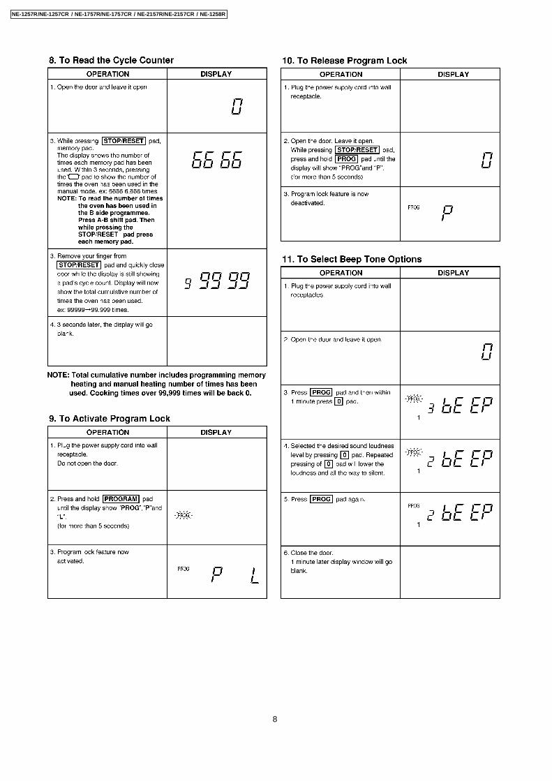
8
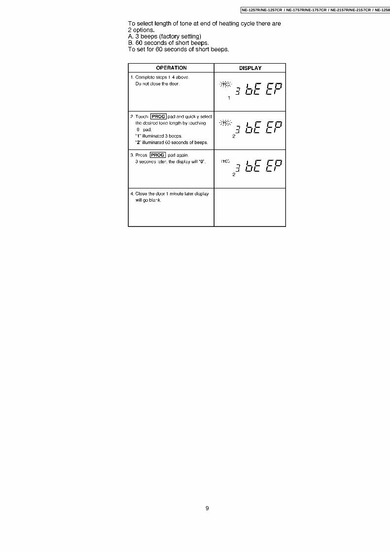
NE-1257R/NE-1257CR / NE-1757R/NE-1757CR / NE-2157R/NE-2157CR / NE-1258R
9
NE-1257R/NE-1257CR / NE-1757R/NE-1757CR / NE-2157R/NE-2157CR / NE-1258

Wiring RequirementsNo other appliance should share the circuit with the microwaveoven. If it does, the branch circuit fuse may overload and eithercause the oven to heat slower than expected or blow the fuse. 1. For Mode NE-1257
The oven must be on a SEPARATE, 20 Amp, 60 Hz-120VGROUNDED CIRCUIT.
2. For Model NE-1757 a. This oven must be on a separate, 60 Hz GROUNDED
CIRCUIT-minimum 15 amps. b. The microwave ovens are built to operate on 2 different
voltages (230 V or 208 V). Be sure that the voltageselector connector (on the back of the oven) is set foryour power supply. Connecting oven to 230 volt line with208 voltage setting is dangerous and may result inoverheating of the electrical components thusshortening their life expectancy or possibly causing afire or other accident. Connecting oven to 230 volt linewith 208 voltage will lower the power output of the oven,resulting in slower heating of the food. Panasonic isNOT responsible for damage resulting from the use ofthe oven with other than specified voltage.
3. For Model NE-2157 a. This oven must be on a separate, 60 Hz GROUNDED
CIRCUIT-minimum 20 amps. b. The microwave ovens are built to operate on 2 different
voltages (230 V or 208 V). Be sure that the voltageselector connector (on the back of the oven) is set foryour power supply. Connecting oven to 230 volt line with208 voltage setting is dangerous and may result inoverheating of the electrical components thusshortening their life expectancy or possibly causing afire or other accident. Connecting oven to 230 volt linewith 208 voltage will lower the power output of the oven,resulting in slower heating of the food. Panasonic isNOT responsible for damage resulting from the use of
the oven with other than specified voltage.
Power Source Voltage SelectionThe microwave oven Models NE-1757 & NE-2157 are factoryset for 208 V operation. For 230 V operation, the followingselection MUST be made.(Step 1) Unscrew the voltage selection panel cover which islocated on the back of the oven. Do not remove any other partsfrom the oven.(Step 2) Remove the while connector and plug the blackconnector into the socket.(Step 3) Store the unused white connector in the rectangularopening.(Step 4) Reattach the voltage adjustment panel cover to thecabinet.For 230 V - Use black connector plug.For 208 V - Use white connector plug.To go from 230 V to 208 V circuit follow steps 1-4 above,except at step 2, plug the white connector plug into the socketand store the black plug in the rectangular opening.
3 WIRING REQUIREMENTS AND POWER SOURCEVOLTAGE SELECTION
10
NE-1257R/NE-1257CR / NE-1757R/NE-1757CR / NE-2157R/NE-2157CR / NE-1258R

4 SCHEMATIC DIAGRAM (NE-1257R, NE-1258R)
11
NE-1257R/NE-1257CR / NE-1757R/NE-1757CR / NE-2157R/NE-2157CR / NE-1258

5 SCHEMATIC DIAGRAM (NE-1257CR)
12
NE-1257R/NE-1257CR / NE-1757R/NE-1757CR / NE-2157R/NE-2157CR / NE-1258R
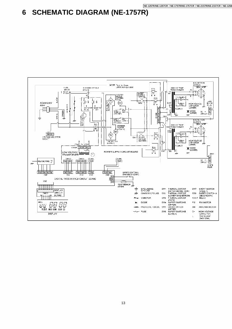
6 SCHEMATIC DIAGRAM (NE-1757R)
13
NE-1257R/NE-1257CR / NE-1757R/NE-1757CR / NE-2157R/NE-2157CR / NE-1258

7 SCHEMATIC DIAGRAM (NE-1757CR)
14
NE-1257R/NE-1257CR / NE-1757R/NE-1757CR / NE-2157R/NE-2157CR / NE-1258R

8 SCHEMATIC DIAGRAM (NE-2157R)
15
NE-1257R/NE-1257CR / NE-1757R/NE-1757CR / NE-2157R/NE-2157CR / NE-1258

9 SCHEMATIC DIAGRAM (NE-2157CR)
16
NE-1257R/NE-1257CR / NE-1757R/NE-1757CR / NE-2157R/NE-2157CR / NE-1258R

10 WIRING DIAGRAM (NE-1257R, NE-1258R)NOTE: When replacing, check the lead wire color as shown.
17
NE-1257R/NE-1257CR / NE-1757R/NE-1757CR / NE-2157R/NE-2157CR / NE-1258

11 WIRING DIAGRAM (NE-1257CR)NOTE: When replacing, check the lead wire color as shown.
18
NE-1257R/NE-1257CR / NE-1757R/NE-1757CR / NE-2157R/NE-2157CR / NE-1258R

12 WIRING DIAGRAM (NE-1757R)NOTE: When replacing, check the lead wire color as shown.
19
NE-1257R/NE-1257CR / NE-1757R/NE-1757CR / NE-2157R/NE-2157CR / NE-1258

13 WIRING DIAGRAM (NE-1757CR)NOTE: When replacing, check the lead wire color as shown.
20
NE-1257R/NE-1257CR / NE-1757R/NE-1757CR / NE-2157R/NE-2157CR / NE-1258R

14 WIRING DIAGRAM (NE-2157R)NOTE: When replacing, check the lead wire color as shown.
21
NE-1257R/NE-1257CR / NE-1757R/NE-1757CR / NE-2157R/NE-2157CR / NE-1258

15 WIRING DIAGRAM (NE-2157CR)NOTE: When replacing, check the lead wire color as shown.
22
NE-1257R/NE-1257CR / NE-1757R/NE-1757CR / NE-2157R/NE-2157CR / NE-1258R

Variable power cooking controlThe coil of power relay A and B are energized intermittently bythe digital programmer circuit, when the oven is set to MEDIUMor DEFROST power position. The digital programmer circuitcontrols the ON-OFF time of the power relay A and B contacts
in order to vary the output power of the microwave oven. Onecomplete ON and OFF cycle of the power relay is 44 seconds.The relation between indications on the control panel and theoutput power of the microwave oven is as shown in Figure.
16 DESCRIPTION OF OPERATING SEQUENCE
23
NE-1257R/NE-1257CR / NE-1757R/NE-1757CR / NE-2157R/NE-2157CR / NE-1258

Unlike many other appliances, the microwave oven is high-voltage, high-current equipment. Though it is free from dangerin ordinary use, extreme care should be taken during repair.
17.1. Check the groundingDo not operate on a 2-wire extension cord. The microwaveoven is designed to be used in a completely groundedcondition. It is imperative, therefore, to make sure it is properlygrounded before beginning repair work.
17.2. If the door lock, the doorswitch, the door seal or thedoor develops a malfunction,be sure not to operate theoven until complete repairsare made.
If the oven is operated with any of these parts in imperfectcondition, hazardous microwave leakage might occur.
17.3. Warning about the electriccharge in the high voltagecapacitor
For about 30 seconds after the oven is turned off, an electriccharge remains in the high voltage capacitor. When replacingor checking parts, remove the power plug from the outlet, wait30 seconds and short the terminal of the high voltage capacitor(terminal of lead wire from diode) to chassis ground with aninsulated jumper lead wire or an insulated handle screwdriverdischarge.
17.4. When parts must be replaced,always remove the power plugfrom the outlet, and dischargethe high voltage capacitor.
17 CAUTIONS TO BE OBSERVED WHENTROUBLESHOOTING
24
NE-1257R/NE-1257CR / NE-1757R/NE-1757CR / NE-2157R/NE-2157CR / NE-1258R

17.5. Confirm after repair 1. After repair or replacement of parts, make sure that the
screws of the oven, etc. are neither loose nor missing.Microwave might leak if screws are not properly tightened.
2. Make sure that all electrical connections are tight beforeinserting the plug into the wall outlet.
17.6. Avoid inserting nails, wire, etc.through holes in unit duringoperation.
Never insert a wire, nail or any other metal object through thelamp holes on the cavity or any other holes or gaps, becausesuch objects may work as an antenna and cause microwaveleakage.
25
NE-1257R/NE-1257CR / NE-1757R/NE-1757CR / NE-2157R/NE-2157CR / NE-1258

18.1. Replacement of magnetrons(Upper and Lower)
Upper magnetron 1. Discharge electric charge remaining on the high voltage
capacitors. 2. Remove the entire rear panel by removing screws as
shown. 3. Disconnect all lead wires from magnetron and thermal
cutout. 4. Remove the 4 screws holding magnetron. 5. Remove 2 screws holding thermal cutout. 6. Remove the mounting bracket from magnetron and install it
on the new magnetron.Lower magnetron 1. Discharge electric charge remaining on the high voltage
capacitors. 2. Remove the entire rear panel by removing screws as
shown. 3. Carefully place the unit on its left side (H. V. Capacitor
side). 4. Remove the cover by removing 2 screws. 5. Remove the 4 screws holding magnetron by inserting
screwdriver through the 4 openings on bottom plate. 6. Remove 2 screws holding thermal cutout. 7. Remove the mounting bracket from magnetron and install it
on the new magnetron.NOTE: To prevent microwave leakage, tighten mountingscrews properly making sure there is no gap between thewaveguide and the magnetron.
18 DISASSEMBLY AND PARTS REPLACEMENTPROCEDURE
26
NE-1257R/NE-1257CR / NE-1757R/NE-1757CR / NE-2157R/NE-2157CR / NE-1258R

Removal of Positive Lock connectorThe positive lock connector is a specially designed loose freeconnector and you will find this connector in many lead wireconnections. To remove this connector, pull the lead wire bypressing an extruded lever in the center of receptacle terminalas shown.
18.2. Replacement of power supplycircuit board
NOTE: Be sure to ground any static electric charge built upon your body, before handling the power supply P. C. B.and D. P. C.. 1. Disconnect all lead wires from power supply circuit board. 2. Remove the power supply P. C. B. together with its
mounting bracket by first removing the 2 bracket holdingscrews.
3. The power supply P. C. B. can be separated from mountingbracket by removing the 2 L. V. T. holding screws andunfastening the plastic clips.
18.3. Replacement of digitalprogrammer circuit board
1. Remove grounding screw for membrane switch and D. P.C. ground.
2. Remove 3 screws holding control panel assembly to detachit from main unit then remove connectors.
3. Remove 2 screws holding the D. P. C. board and whilepushing back on 2 plastic holding clips, remove the board.
NOTE: Please use care in handling the power supply P. C.B. and D. P. C. board to avoid damage.
27
NE-1257R/NE-1257CR / NE-1757R/NE-1757CR / NE-2157R/NE-2157CR / NE-1258

18.4. Replacement of upper antenna
1. Remove ceiling plate by gently moving the left and righttabs inward while pulling the plate down and outward.
2. Using a small flat screwdriver or the like, remove two plasticclips located on the antenna ring. Nest turn the antenna ringapprox. 1/8 turn clockwise to unhook the tabs and pull off.
18.5. Replacement of floor shelf andlower antenna
1. To remove the floor shelf, insert a screwdriver through thesmall opening on the left side of the oven cavity andcarefully lift the floor shelf.
2. For removal of lower antenna, use the same procedure asupper antenna.
18.6. Replacement of temperaturesensor (Thermal protector)
1. Cut 2 lead wires at the top of sensor terminals.
28
NE-1257R/NE-1257CR / NE-1757R/NE-1757CR / NE-2157R/NE-2157CR / NE-1258R

2. Remove 2 screws holding temp sensor and replace withnew one.
3. Solder the lead wires securely to the sensor terminals.
18.7. Disassembly of door assembly 1. Remove each 2 bolts holding upper and lower hinges. 2. Open the door and while pulling the door outward, work
upper and lower hinges out through the holes of the frontsurface of oven.
3. Remove door C (check cover) from door E by carefullypulling outward starting from the upper right hand corner.
4. Remove 2 screws holding door handle and separate door Afrom door E by carefully freeing catch hooks.
5. Remove door key, door key lever, door key spring andhandle pins from door E.
6. Assemble the door by taking the above steps in a reverseorder.
Replacement 1. When mounting the door to the oven be sure to adjust the
door parallel to the bottom line of the oven face plate bymoving the upper hinge and lower hinge in the directionnecessary for proper alignment.
2. Adjust so that the door has no play between the inner doorsurface and oven front surface. If the door assembly is notmounted properly, microwave may leak from the clearancebetween the door and the oven.
NOTE: Please refer to MEASURENMENT ANDADJUSTMENT.
29
NE-1257R/NE-1257CR / NE-1757R/NE-1757CR / NE-2157R/NE-2157CR / NE-1258

19.1. High voltage transformer 1. Remove connections from the transformer terminals and
check continuity. 2. Normal (cold) resistance readings should be as follows:
Secondary winding Approx. 80Ω—120Ω
Filament winding Approx. 0Ω
Primary winding Approx. 0Ω—3Ω
19.2. High voltage capacitor 1. Check continuity of capacitor with meter on highest OHM
scale. 2. A normal capacitor will show continuity for a short time, and
then indicate 9MΩ once the capacitor is charged. 3. A shorted capacitor will show continuous continuity. 4. An open capacitor will show constant 9MΩ. 5. Resistance between each terminal and chassis should be
infinite.
19.3. MagnetronContinuity checks can only indicate an open filament or ashorted magnetron. To diagnose for an open filament orshorted magnetron. 1. Isolate magnetron from the circuit by disconnecting the
leads. 2. A continuity check across magnetron filament terminals
should indicate one ohm or less. 3. A continuity check between each filament terminal and
magnetron case should read open.
19.4. Diode 1. Isolate the diode from the circuit by disconnecting the leads. 2. With the ohmmeter set on the highest resistance scale,
measure the resistance across the diode terminals.Reverse the meter leads and again observe the resistancereading. Meter with 6V, 9V or higher voltage batteriesshould be used to check the front-to-back resistance of thediode, otherwise an infinite resistance may be read in bothdirections.A normal diode's resistance will be infinite in one directionand several hundred kΩ in the other direction.
19.5. Membrane key board(Membrane switch assembly)
Check continuity between switch terminals, by tapping anappropriate pad on the key board. The contacts assignment ofthe respective pads on the key board is as shown in digitalprogrammer circuit.
19.6. Protector diode 1. Isolate the protector diode assembly from the circuit by
disconnecting its leads. 2. With the ohmmeter set on the highest resistance scale,
measure the resistance across the protector diodeterminals.Reverse the meter leads and again observe the resistancereading. A normal protector diode's resistance will beinfinite in both directions. It is faulty if it shows continuity in
19 COMPONENT TEST PROCEDURE
30
NE-1257R/NE-1257CR / NE-1757R/NE-1757CR / NE-2157R/NE-2157CR / NE-1258R

one or both directions.
19.7. Temp sensor (Thermalprotector)
A temp sensor is mounted on exhaust guide. Its purpose is toautomatically shut off the oven in case the cavity overheats forany reason.The thermal protector will operate at 257°F (125°C).The device is connected to the DPC on touch control models.When the thermal protector exceeds its temperature it will turnoff the power to oven cavity and display will go to reset mode.The cooking program can be reset after cool-down.THERMISTOR RESISTANCE VALUE30K—120K at 10°C—30°C (50°F—86°F)
31
NE-1257R/NE-1257CR / NE-1757R/NE-1757CR / NE-2157R/NE-2157CR / NE-1258
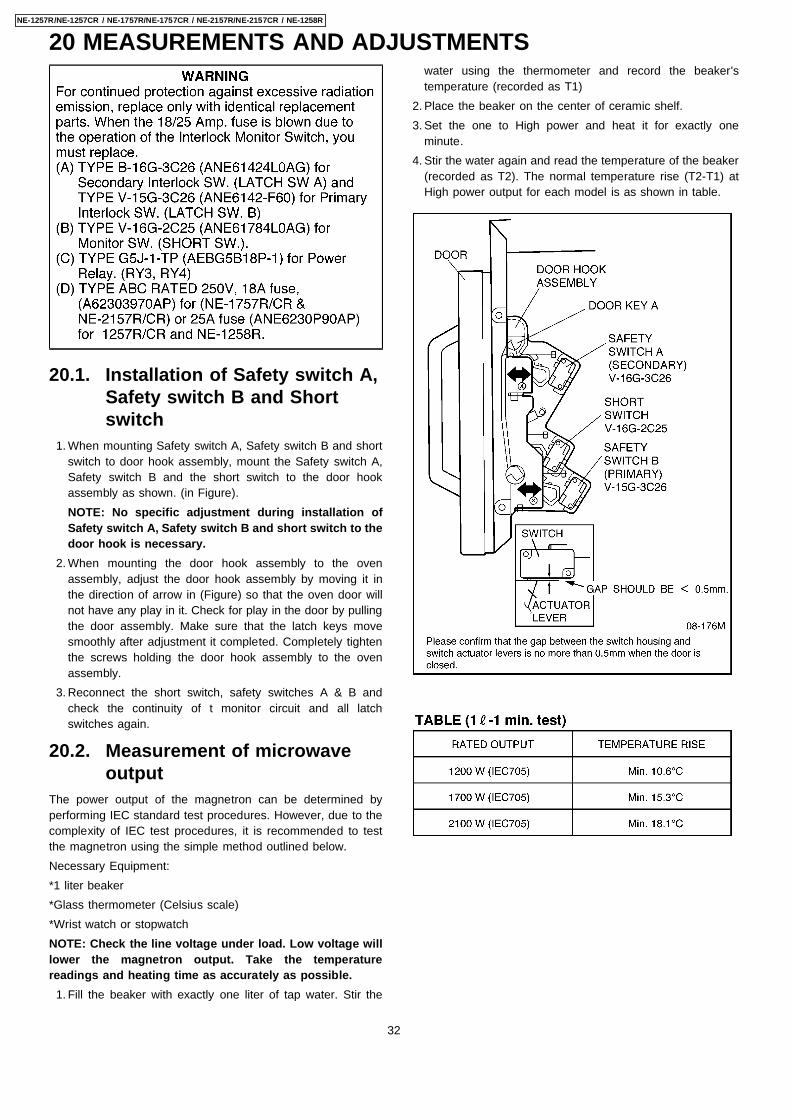
20.1. Installation of Safety switch A,Safety switch B and Shortswitch
1. When mounting Safety switch A, Safety switch B and shortswitch to door hook assembly, mount the Safety switch A,Safety switch B and the short switch to the door hookassembly as shown. (in Figure).NOTE: No specific adjustment during installation ofSafety switch A, Safety switch B and short switch to thedoor hook is necessary.
2. When mounting the door hook assembly to the ovenassembly, adjust the door hook assembly by moving it inthe direction of arrow in (Figure) so that the oven door willnot have any play in it. Check for play in the door by pullingthe door assembly. Make sure that the latch keys movesmoothly after adjustment it completed. Completely tightenthe screws holding the door hook assembly to the ovenassembly.
3. Reconnect the short switch, safety switches A & B andcheck the continuity of t monitor circuit and all latchswitches again.
20.2. Measurement of microwaveoutput
The power output of the magnetron can be determined byperforming IEC standard test procedures. However, due to thecomplexity of IEC test procedures, it is recommended to testthe magnetron using the simple method outlined below.Necessary Equipment:*1 liter beaker*Glass thermometer (Celsius scale)*Wrist watch or stopwatchNOTE: Check the line voltage under load. Low voltage willlower the magnetron output. Take the temperaturereadings and heating time as accurately as possible. 1. Fill the beaker with exactly one liter of tap water. Stir the
water using the thermometer and record the beaker'stemperature (recorded as T1)
2. Place the beaker on the center of ceramic shelf. 3. Set the one to High power and heat it for exactly one
minute. 4. Stir the water again and read the temperature of the beaker
(recorded as T2). The normal temperature rise (T2-T1) atHigh power output for each model is as shown in table.
20 MEASUREMENTS AND ADJUSTMENTS
32
NE-1257R/NE-1257CR / NE-1757R/NE-1757CR / NE-2157R/NE-2157CR / NE-1258R

NOTE: The U. S. Government standard is 5 mW/cm2 whilein the customer's home. 2 mW/cm2 stated here is our ownvoluntary standard. (1 mW/cm2 for Canada)
21.1. EquipmentNote before measuring. 1. Do not exceed meter full scale deflection. Leakage monitor
should initially be set to the highest scale. 2. To prevent false readings the test probe should be held by
the grip portion of the handle only and moved along theshaded area shown in Figure no faster than 1 inch/sec (2.5cm/sec).
3. Leakage with the outer panel removed — less than 5mW/cm2.
4. Leakage for a fully assembled oven with door normallyclosed — less than 2 mW/cm2 (1 mW/cm2 for Canada).
5. Leakage for a fully assembled oven [Before the latch switch(primary) is interrupted] while pulling the door — less than2 mW/cm2.
1. Pour 275± 15cc (9ozs ± 1/2oz) of 20 ± 5°C (68± 9°F) waterin a beaker which has graduations to 600cc, and place inthe center of the oven.
2. Set the radiation monitor to 2450MHz and use it followingthe manufacture's recommended test procedure to assurecorrect results.
3. When measuring the leakage, always use the 2 inch (5 cm)spacer supplied with the probe.
4. Tap the start pad or set the timer and with the magnetronoscillating, measure the leakage by holding the probeperpendicular to the surface being measured.
1. Measurement with the outer pane removed.Whenever you replace the magnetron, measure forradiation leakage before the outer panel is installed andafter all necessary components are replaced or adjusted.Special care should be taken when measuring around themagnetron.
2. Measurements with a fully assembled oven.After all components, including outer panel are fullyassembled, measure for radiation leakage around the door
periphery, the door viewing window, the exhaust openingand air inlet openings.
21.2. Record keeping andnotification after measurement
1. After any adjustment or repair to a microwave oven, aleakage reading must be taken. Record this leakagereading on the repair ticket even if it is zero.A copy of this repair ticket and the microwave leakagereading should be kept by repair facility.
2. Should the radiation leakage be more than 2 mW/cm2 (1mW/cm2 for Canada) after determining that all parts are ingood condition, functioning properly, and genuinereplacement parts as listed in this manual have been used,immediately notify PHCC, PSC or PCI.
21.3. At least once a year, have theradiation monitor checked forcalibration by itsmanufacturer.
21 PROCEDURE FOR MEASURING MICROWAVE ENERGYLEAKAGE
33
NE-1257R/NE-1257CR / NE-1757R/NE-1757CR / NE-2157R/NE-2157CR / NE-1258

34
NE-1257R/NE-1257CR / NE-1757R/NE-1757CR / NE-2157R/NE-2157CR / NE-1258R

22 TROUBLESHOOTING GUIDE
35
NE-1257R/NE-1257CR / NE-1757R/NE-1757CR / NE-2157R/NE-2157CR / NE-1258

23 EXPLODED VIEW AND PARTS LIST
36
NE-1257R/NE-1257CR / NE-1757R/NE-1757CR / NE-2157R/NE-2157CR / NE-1258R
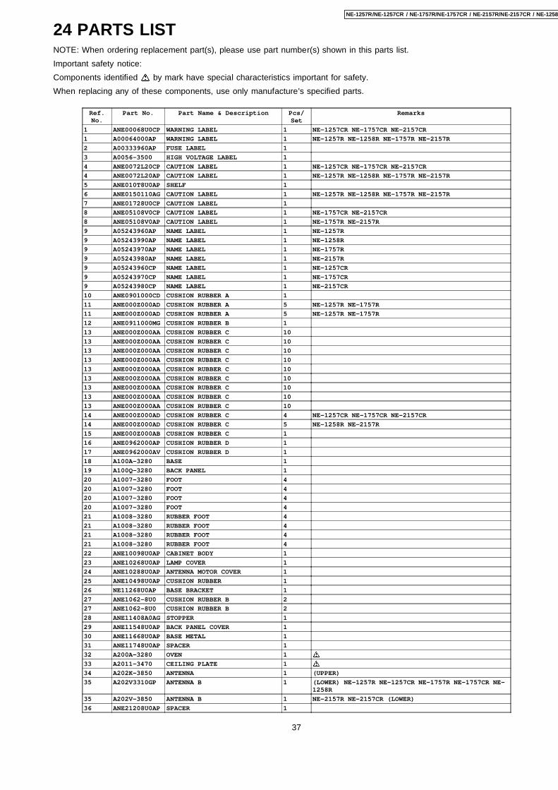
24 PARTS LISTNOTE: When ordering replacement part(s), please use part number(s) shown in this parts list.Important safety notice:Components identified by mark have special characteristics important for safety.When replacing any of these components, use only manufacture's specified parts.
Ref.No.
Part No. Part Name & Description Pcs/Set
Remarks
1 ANE00068U0CP WARNING LABEL 1 NE-1257CR NE-1757CR NE-2157CR
1 A00064000AP WARNING LABEL 1 NE-1257R NE-1258R NE-1757R NE-2157R
2 A00333960AP FUSE LABEL 1
3 A0056-3500 HIGH VOLTAGE LABEL 1
4 ANE0072L20CP CAUTION LABEL 1 NE-1257CR NE-1757CR NE-2157CR
4 ANE0072L20AP CAUTION LABEL 1 NE-1257R NE-1258R NE-1757R NE-2157R
5 ANE010T8U0AP SHELF 1
6 ANE0150110AG CAUTION LABEL 1 NE-1257R NE-1258R NE-1757R NE-2157R
7 ANE01728U0CP CAUTION LABEL 1
8 ANE05108V0CP CAUTION LABEL 1 NE-1757CR NE-2157CR
8 ANE05108V0AP CAUTION LABEL 1 NE-1757R NE-2157R
9 A05243960AP NAME LABEL 1 NE-1257R
9 A05243990AP NAME LABEL 1 NE-1258R
9 A05243970AP NAME LABEL 1 NE-1757R
9 A05243980AP NAME LABEL 1 NE-2157R
9 A05243960CP NAME LABEL 1 NE-1257CR
9 A05243970CP NAME LABEL 1 NE-1757CR
9 A05243980CP NAME LABEL 1 NE-2157CR
10 ANE0901000CD CUSHION RUBBER A 1
11 ANE000Z000AD CUSHION RUBBER A 5 NE-1257R NE-1757R
11 ANE000Z000AD CUSHION RUBBER A 5 NE-1257R NE-1757R
12 ANE0911000MG CUSHION RUBBER B 1
13 ANE000Z000AA CUSHION RUBBER C 10
13 ANE000Z000AA CUSHION RUBBER C 10
13 ANE000Z000AA CUSHION RUBBER C 10
13 ANE000Z000AA CUSHION RUBBER C 10
13 ANE000Z000AA CUSHION RUBBER C 10
13 ANE000Z000AA CUSHION RUBBER C 10
13 ANE000Z000AA CUSHION RUBBER C 10
13 ANE000Z000AA CUSHION RUBBER C 10
13 ANE000Z000AA CUSHION RUBBER C 10
14 ANE000Z000AD CUSHION RUBBER C 4 NE-1257CR NE-1757CR NE-2157CR
14 ANE000Z000AD CUSHION RUBBER C 5 NE-1258R NE-2157R
15 ANE000Z000AB CUSHION RUBBER C 1
16 ANE0962000AP CUSHION RUBBER D 1
17 ANE0962000AV CUSHION RUBBER D 1
18 A100A-3280 BASE 1
19 A100Q-3280 BACK PANEL 1
20 A1007-3280 FOOT 4
20 A1007-3280 FOOT 4
20 A1007-3280 FOOT 4
20 A1007-3280 FOOT 4
21 A1008-3280 RUBBER FOOT 4
21 A1008-3280 RUBBER FOOT 4
21 A1008-3280 RUBBER FOOT 4
21 A1008-3280 RUBBER FOOT 4
22 ANE10098U0AP CABINET BODY 1
23 ANE10268U0AP LAMP COVER 1
24 ANE10288U0AP ANTENNA MOTOR COVER 1
25 ANE10498U0AP CUSHION RUBBER 1
26 NE11268U0AP BASE BRACKET 1
27 ANE1062-8U0 CUSHION RUBBER B 2
27 ANE1062-8U0 CUSHION RUBBER B 2
28 ANE11408A0AG STOPPER 1
29 ANE11548U0AP BACK PANEL COVER 1
30 ANE11668U0AP BASE METAL 1
31 ANE11748U0AP SPACER 1
32 A200A-3280 OVEN 1
33 A2011-3470 CEILING PLATE 1
34 A202K-3850 ANTENNA 1 (UPPER)
35 A202V3310GP ANTENNA B 1 (LOWER) NE-1257R NE-1257CR NE-1757R NE-1757CR NE-1258R
35 A202V-3850 ANTENNA B 1 NE-2157R NE-2157CR (LOWER)
36 ANE21208U0AP SPACER 1
37
NE-1257R/NE-1257CR / NE-1757R/NE-1757CR / NE-2157R/NE-2157CR / NE-1258

Ref.No.
Part No. Part Name & Description Pcs/Set
Remarks
37 A8251-3180 SPACER 1
38 A3020-3850 DOOR HOOK A 1
39 A3136-3470 HOOK SPACER A 1
40 A3137-3850 HOOK SPACER B 1
41 A3138-3470 HOOK SPACER C 1
42 A31863960CP DOOR PANEL 1 NE-1257CR
42 A31863960AP DOOR PANEL 1 NE-1257R
42 A31863990AP DOOR PANEL 1 NE-1258R
42 A31863970CP DOOR PANEL 1 NE-1757CR
42 A31863970AP DOOR PANEL 1 NE-1757R
42 A31863980AP DOOR PANEL 1 NE-2157R
42 A31863980CP DOOR PANEL 1 NE-2157CR
43 ANE32398U0AP SPRING 1
44 ANE32628U0AP SPRING 3
44 ANE32628U0AP SPRING 3
45 A400A3650AP FAN MOTOR 2 NE-1257CR NE-1257R NE-1258R (50W)
45 A400A3660AP FAN MOTOR 2 NE-1757CR NE-1757R (54W)
45 A400A3780AP FAN MOTOR 2 NE-2157R NE-2157CR (51W)
46 A400B-3280 AIR FILTER FLAME 1
47 A4024-3180 EXHAUST GUIDE A 1
48 ANE40258U0AP AIR GUIDE A 1
49 ANE40268U0AP AIR GUIDE B 1
50 A4091-3280 SCREW 1 FOR AIR FILTER FLAME
51 ANE41038U0AP AIR GUIDE CUSHION B 1
52 ANE50328U0AP MAGNETRON BRACKET 2
52 ANE50328U0AP MAGNETRON BRACKET 2
53 A50493650CP FIRE BARRIER 1 NE-1257CR NE-1757CR
53 A50493780CP FIRE BARRIER 1 NE-2157CR
54 A603L3960AP D.P.CIRCUIT (U) 1 NE-1257CR NE-1257R NE-1258R RTL (W/COMPONENT)
54 A603L3970AP D.P.CIRCUIT (U) 1 NE-1757CR NE-1757R RTL (W/COMPONENT)
54 A603L3980AP D.P.CIRCUIT (U) 1 NE-2157R NE-2157CR RTL (W/COMPONENT)
55 ANE6030540AP INCANDESCENT LAMP 1 NE-1257CR NE-1257R NE-1258R (125V 20W)
55 A60304080BP INCANDESCENT LAMP 1 NE-1757CR NE-1757R NE-2157R NE-2157CR (240V 20W)
56 ANE60408U0AP OVEN LAMP SHEET 2 NE-1257CR NE-1257R NE-1258R NE-1757CR NE-1757R
56 A60403780AP OVEN LAMP SHEET 2 NE-2157R NE-2157CR
57 ANE61458U0AP THERMAL CUTOUT 2
57 ANE61458U0AP THERMAL CUTOUT 2
57 ANE61458U0AP THERMAL CUTOUT 2
58 A605S3650CP PC BOARD H (U) 1 NE-1257CR
58 A605S3660CP PC BOARD H (U) 1 NE-1757CR NE-2157CR
59 ANE60708U0BP INSULATION SHEET A 1
60 A60713310BP INSULATION SHEET B 1
61 A60903650AP H.V.CAPACITOR 2 NE-1257CR NE-1257R NE-1258R
61 A60903660AP H.V.CAPACITOR 2 NE-1757CR NE-1757R
61 A60903780AP H.V.CAPACITOR 2 NE-2157R NE-2157CR
62 A6070-3280 INSULATION SHEET A 2
63 ANE6142-F60 MICROSWITCH 2 (V-15G-3C26)PRIMARY LATCH SWITCH
64 ANE61424L0AG MICROSWITCH 1 (V-16G-3C26)SECONDARY LATCH SWITCH
65 A6144-3280 ANTENNA MOTOR 1 NE-1257CR NE-1257R NE-1258R NE-1757CR NE-1757R(2.5W)
65 A61443030GP ANTENNA MOTOR 1 NE-2157R NE-2157CR (2.5W)
68 A61443660AP ANTENNA MOTOR 1 NE-1757CR NE-1757R NE-2157R NE-2157CR (2.5W)
68 A61446030AP ANTENNA MOTOR 1 NE-1257CR NE-1257R NE-1258R (2.5W)
69 A65943030GP MOTOR COVER 1
70 ANE61458U0AP THERMAL CUTOUT 1 NE-1257R NE-1757R
71 ANE61454L0AG THERMAL CUTOUT 1 NE-1257CR NE-1757CR
71 A61454050AP THERMAL CUTOUT 1 NE-2157R NE-2157CR
72 A61524210AA SOCKET 1
73 A6170-3280 INSULATION SHEET C 1 NE-1257CR NE-1757CR NE-2157CR
74 ANE61784L0AG MICRO SWITCH 2 (V-16G-2C25) SHORT SWITCH
75 ANE61888U0AP CAPACITOR BRACKET 2
76 A62023960AP DIODE SI 2 NE-1257CR NE-1257R NE-1258R NE-1757CR NE-1757R
76 A62023880AP DIODE SI 2 NE-2157R NE-2157CR
77 A621B3650AP H.V.TRANSFORMER 2 NE-1257CR NE-1257R NE-1258R
77 A621B3660AP H V.TRANSFORMER 2 NE-1757CR NE-1757R
77 A621B3780AP H.V.TRANSFORMER 2 NE-2157R NE-2157CR
78 ANE62298U0AP MOUNTING BRACKET 1
79 ANE6230P90AP FUSE 1 NE-1257CR NE-1257R NE-1258R (25A)
79 A62303970AP FUSE 2 NE-1757CR NE-1757R NE-2157R NE-2157CR (18A)
80 A62314000AP FUSE HOLDER 1 NE-1257R NE-1258R
80 A62314000AP FUSE HOLDER 2 NE-1757R NE-2157R
81 ANE6238X20AP SPACER 1
82 ANE64086Q0AP WASHER 1
38
NE-1257R/NE-1257CR / NE-1757R/NE-1757CR / NE-2157R/NE-2157CR / NE-1258R

Ref.No.
Part No. Part Name & Description Pcs/Set
Remarks
83 A6408-3280 WASHER 1
84 ANE65448U0AP SPACER A 1
85 A6585-3280 P.C.B.HOLDER 1
86 ANE66038U0AP OVEN LAMP BRACKET 1
87 ANE66268U0AP THERMAL CUTOUT MOUNT 1 NE-1257R NE-1258R NE-1757R
88 A6688-3180 P.C.B.COVER 1
89 A692M3650AP L.V.TRANSFORMER (U) 1 NE-1257CR NE-1257R NE-1258R
89 A692M3660AP L.V.TRANSFORMER (U) 1 NE-1757CR NE-1757R NE-2157R NE-2157CR
90 B900C3650CP AC CORD W/PLUG 1 NE-1257CR
90 B900C3650AP AC CORD W/PLUG 1 NE-1257R NE-1258R
90 B900C3660CP AC CORD W/PLUG 1 NE-1757CR
90 B900C3660AP AC CORD W/PLUG 1 NE-1757R
90 B900C3780AP ACCORD W/PLUG 1 NE-2157R
90 B900C3780CP AC CORD W/PLUG 1 NE-2157CR
91 ANE9027510RN CORD BUSHING 1
92 ANE9035P90AP CORD BRACKET 1
93 ANE90828U0AP CLIP(BLACK) 1
94 ANE91438U0AP CLIP(GLAY) 1 NE-1257CR NE-1257R NE-1258R
95 ANE91448U0AP BRACKET 1
96 ANE91628U0AP CLIP B 1
97 ANE91658V0AP CLIP 4
97 ANE91658V0AP CLIP 4
98 XTC4+10BC SCREW 4 (4X10) FOR CABINET BODY
98 XTC4+10BC SCREW 4 (4X10) FOR CABINET BODY
98 XTC4+10BC SCREW 4 (4X10) FOR CABINET BODY
99 XTC4+10FC SCREW 1 (4X10) FORLAMP COVER
100 XTC4+12BK SCREW (BLACK) 2 (4X12)FOR BASE
100 XTC4+12BK SCREW (BLACK) 2 (4X12)FOR BASE
101 XTEANE5+10B SCREW 4 (5X10)FOR H.V.TRANSFORMER
102 XTT4+8E SCREW 1 (4X8) FOR BACK PANEL COVER
103 XTWANE3+8EX SCREW 2 (3X8) FOR TEMP SENSOR
104 XTW3+8B SCREW 4 (3X8) FOR FOOT
105 XWC4BPN WASHER 2 FOR BACK PANEL COVER, LAMP COVER
105 XWC4BPN WASHER 2 FOR BACK PANEL COVER, LAMP COVER
106 XYD4+EE12F SCREW 11 (4X12)FOR DIODE, CAPACITOR BRACKET, AC CORD, MOTORCOVER, BASE METAL ETC
106 XYD4+EE12F SCREW 11 (4X12)FOR DIODE, CAPACITOR BRACKET, AC CORD, MOTORCOVER, BASE METAL ETC
106 XYD4+EE12F SCREW 11 (4X12)FOR DIODE, CAPACITOR BRACKET, AC CORD, MOTORCOVER, BASE METAL ETC
106 XYD4+EE12F SCREW 11 (4X12)FOR DIODE, CAPACITOR BRACKET, AC CORD, MOTORCOVER, BASE METAL ETC
106 XYD4+EE12F SCREW 11 (4X12)FOR DIODE, CAPACITOR BRACKET, AC CORD, MOTORCOVER, BASE METAL ETC
106 XYD4+EE12F SCREW 11 (4X12)FOR DIODE, CAPACITOR BRACKET, AC CORD, MOTORCOVER, BASE METAL ETC
106 XYD4+EE12F SCREW 11 (4X12)FOR DIODE, CAPACITOR BRACKET, AC CORD, MOTORCOVER, BASE METAL ETC
106 XYD4+EE12F SCREW 11 (4X12)FOR DIODE, CAPACITOR BRACKET, AC CORD, MOTORCOVER, BASE METAL ETC
106 XYD4+EE12F SCREW 11 (4X12)FOR DIODE, CAPACITOR BRACKET, AC CORD, MOTORCOVER, BASE METAL ETC
106 XYD4+EE12F SCREW 11 (4X12)FOR DIODE, CAPACITOR BRACKET, AC CORD, MOTORCOVER, BASE METAL ETC
106 XYD4+EE12F SCREW 11 (4X12)FOR DIODE, CAPACITOR BRACKET, AC CORD, MOTORCOVER, BASE METAL ETC
106 XYD4+EE12F SCREW 11 (4X12)FOR DIODE, CAPACITOR BRACKET, AC CORD, MOTORCOVER, BASE METAL ETC
107 XYEANE5+C16T SCREW 8 (5X16) FOR MAGNETRON
107 XYEANE5+C16T SCREW 8 (5X16) FOR MAGNETRON
107 XYEANE5+C16T SCREW 8 (5X16) FOR MAGNETRON
107 XYEANE5+C16T SCREW 8 (5X16) FOR MAGNETRON
108 XYEA4+C16TS SCREW 2
109 2M210-M1F1 MAGNETRON 2 NE-1257R NE-1258R NE-1757R
109 2M210-M1G MAGNETRON 2 NE-1257CR NE-1757CR
109 2M244-M1F1 MAGNETRON 2 NE-2157R NE-2157CR
109 2M244-M1G MAGNETRON 2 NE-2157R
110 A601L5150AP TEMP SENSOR 1
111 ANE0245X00AP DHHS LABEL 1 NE-1257R NE-1258R NE-1757R NE-2157R
111 A04115020CQ CSA LABEL 1 NE-1257CR NE-1757CR NE-2157CR
39
NE-1257R/NE-1257CR / NE-1757R/NE-1757CR / NE-2157R/NE-2157CR / NE-1258

25 DOOR ASSEMBLY
Ref.No.
Part No. Part Name & Description Pcs/Set
Remarks
D1 A3145-3500 DOOR SCREEN A 1
D2 ANE31468U0AP DOOR SCREEN B 1
D3 ANE30038U0AP DOOR FRAME(U) 1
D4 ANE301A8U0AP DOOR A 1
D5 A301H-3850 DOOR KEY LEVER B 1
D6 ANE301Q8U0AP DOOR E(U) 1
D7 A3018-3850 DOOR KEY A 1
D8 A3019-3850 DOOR KEY B 1
D9 ANE30218U0AP DOOR KEY SPRING 1
D10 ANE30562Q0AP HANDLE PIN 2
D10 ANE30562Q0AP HANDLE PIN 2
D11 A30703170GP HANDLE PEICE A 1
D12 ANE3081P60AP DOOR HINGE SPACER 1
D13 ANE30858U0AP DOOR C 1
D14 ANE30078U0AP HINGE 2
D14 ANE30078U0AP HINGE 2
D15 ANE31348U0AP HANDLE PEICE B 1
D16 XYEA4+C16TS SCREW 2 (4X16)
D16 XYEA4+C16TS SCREW 2 (4X16)
40
NE-1257R/NE-1257CR / NE-1757R/NE-1757CR / NE-2157R/NE-2157CR / NE-1258R

26 ESCUTCHEON BASE ASSEMBLY
Ref.No.
Part No. Part Name & Description Pcs/Set
Remarks
E1 A8337-3280 ESCUTCHEON SHEET 1
E2 A603M3310GP PC BOARD B (U) 1
E3 A64793310QP MEMBRANE SWITCH 1
E4 A6590-3280 FLAT CABLE 1
E5 ANE80018U0AP ESCUTCHEON A 1
E6 ANE80028U0AP ESCUTCHEON B 1
E7 ANE80068U0AP ESCUTCHEON D 1
E8 A800L3310QP ESCUTCHEON BASE 1
41
NE-1257R/NE-1257CR / NE-1757R/NE-1757CR / NE-2157R/NE-2157CR / NE-1258

27 PACKING AND ACCESSORIES
Ref.No.
Part No. Part Name & Description Pcs/Set
Remarks
P1 A00033960CP INSTRUCTION BOOK 1 NE-1257CR NE-1757CR NE-2157CR
P1 A00033960AP INSTRUCTION BOOK 1 NE-1257R NE-1258R NE-1757R NE-2157R
P2 A04203960AP OPERATING GUIDE 1
P3 A01023960CP PACKING CASE PAPER 1 NE-1257CR
P3 A01023960AP PACKING CASE PAPER 1 NE-1257R
P3 A01023990AP PACKING CASE PAPER 1 NE-1258R
P3 A01023970CP PACKING CASE PAPER 1 NE-1757CR
P3 A01023970AP PACKING CASE PAPER 1 NE-1757R
P3 A01023980AP PACKING CASE PAPER 1 NE-2157R
P3 A01023980CP PACKING CASE PAPER 1 NE-2157CR
P4 ANE01048U0AP UPPER FILLER 1
P5 ANE01058U0AP LOWER FILLER 1
P6 A01065200AP VINYL COVER 1
P7 ANE01072Q0AP DOOR SHEET 1
P8 A01083310GP TRAY PACKING 1
P9 ANE01268U0AP REIN FORCE MATERIAL 1
P10 A01453230BP DOOR SHEET B 1
P11 A1134-3280 FOOT BRACKET 1
42
NE-1257R/NE-1257CR / NE-1757R/NE-1757CR / NE-2157R/NE-2157CR / NE-1258R

28 WIRING MATERIAL
Ref.No.
Part No. Part Name & Description Pcs/Set
Remarks
W1 A030A3960CP LEAD WIRE HARNESS 1 NE-1257CR
W1 A030A3960AP LEAD WIRE HARNESS 1 NE-1257R NE-1258R
W1 A030A3970CP LEAD WIRE HARNESS 1 NE-1757CR
W1 A030A3970AP LEAD WIRE HARNESS 1 NE-1757R
W1 A030A3980AP LEAD WIRE HARNESS 1 NE-2157R NE-2157CR
W1 A030A3980CP LEAD WIRE HARNESS 1 NE-2157CR
W2 A030H3960AP LEAD WIRE HARNESS 1
W3 A50966520UP FERRITE CORE 2 NE-1257CR NE-1757CR NE-2157CR
W3 A50966520UP FERRITE CORE 2 NE-1257CR NE-1757CR NE-2157CR
W3 A50966520UP FERRITE CORE 2 NE-1257CR NE-1757CR NE-2157CR
W4 A606V3960AP PROTECTOR DIODE 1
W5 A606W3960AP PROTECTOR DIODE B 1
W6 A61393230BP INSULATION TUBE 1
W7 ERZC10DK471U VARISTOR 1
W8 ERZV10D112 VARISTOR 2
W9 ANE0352-3280 LEAD WIRE 1 FOR ANTENNA MOTOR
43
NE-1257R/NE-1257CR / NE-1757R/NE-1757CR / NE-2157R/NE-2157CR / NE-1258

29 REF. NO. 89 L. V. TRANSFORMER (U)Ref.No.
Part No. Part Name & Description Pcs/Set
Remarks
ANE61158U0AP POWER RELAYBRACKET 1
ANE65448U0AP SPACER A 6
ANE65458U0AP SPACER B 2
A6338-3280 INSULATION SHEET B 1
XYN3+F25S SCREW 2 3X25
CN100 AEEMMF01F05W CONNECTOR 1 5PIN
CN101 AEEMMF03F06W CONNECTOR 1 6PIN
CN102 AEEMMD04907W CONNECTOR 1 7PIN
CN103 AEEMMD04907R CONNECTOR 1 7PIN RED
CN104 AEEMMF00703W CONNECTOR 1 3PIN
CN105 AEEMMF00703R CONNECTOR 1 3PIN RED
CN106 AEEMMD24910W CONNECTOR 1 10PIN
D100101102103104105
MA196-(TA5) DIODE SI 6 NE-1257CR NE-1257R NE-1258R
D100101102103104105108
MA196-(TA5) DIODE SI 7 NE-1757CR NE-1757R NE-2157R NE-1257CR
D106107
AEDNERA1506 DIODE SI 2
IC100101
AEICP25011HL IC 2
R100101102103
ERDS1TJ434T CARBON FILM RESISTOR 4 430K 1/2W 5%
RY1 AEBG5B18P-1 POWER RELAY 1 G5B-1-ER18
RY2 AEBG5B1E18 POWER RELAY 1 G5B-1-E 18VDC
RY3 45
AEG5J1EM18B POWER RELAY 5 NE-1757CR NE-1757R NE-2157R NE-2157CR(G5J-1-TP-M-ER18)
RY3 46 7
AEG5J1EM18B POWER RELAY 4 NE-1257CR NE-1257R NE-1258R (G5J-1-TP-M-ER18)
T100 ETP43KZN41EN L.V.TRANSFORMER 1 NE-1257CR NE-1257R NE-1258R
T100 ETP43KZN61DN L.V.TRANSFORMER 1 NE-1757CR NE-1757R NE-2157R NE-2157CR
ZD101102
AEDZ13ES2T1 DIODE SI 2
30 REF. NO. 58 NOISE FILTER (U)
Ref.No.
Part No. Part Name & Description Pcs/Set
Remarks
C504505
ECKMNA222ME CERAMIC CAPACITOR 2 NE-1257CR NE-1757CR NE-2157CR (0.0022MF 250V)
C506 ECQU2A224MNA POLYESTER CAPACITOR 1 NE-1257CR NE-1757CR 0.22MF 250V
D502 ERZV10D911E1 VARISTOR 1 NE-1257CR NE-1757CR
D503 ERZV10D182E2 VARISTOR 1 NE-1257CR NE-1757CR
D504 ERZV10D621CS VARISTOR 1 NE-1257CR NE-1757CR
F500501
A6116-3280 TERMINAL BOARD 1 NE-1257CR NE-1757CR
F500501
A62316010BP FUSE HOLDER 4 NE-1757CR
F501 A62316010BP FUSE HOLDER 4 NE-1257CR
L500 A621A-1810 FILTER COIL 1 NE-1257CR NE-1757CR NE-1257CR
44
NE-1257R/NE-1257CR / NE-1757R/NE-1757CR / NE-2157R/NE-2157CR / NE-1258R

31 REF. NO. E2 P. C. BOARD (U)
Ref.No.
Part No. Part Name & Description Pcs/Set
Remarks
CN250 AEEMHLIM21S CONNECTOR 1 21PIN
DISP250
A64563080AP FLOURESCENT TUBE 1 FV443
ANE82848U2AP SPACER 1
45
NE-1257R/NE-1257CR / NE-1757R/NE-1757CR / NE-2157R/NE-2157CR / NE-1258

32 DIGITAL PROGRAMMER CIRCUITSCHEMATIC DIAGRAM
46
NE-1257R/NE-1257CR / NE-1757R/NE-1757CR / NE-2157R/NE-2157CR / NE-1258R

47
NE-1257R/NE-1257CR / NE-1757R/NE-1757CR / NE-2157R/NE-2157CR / NE-1258
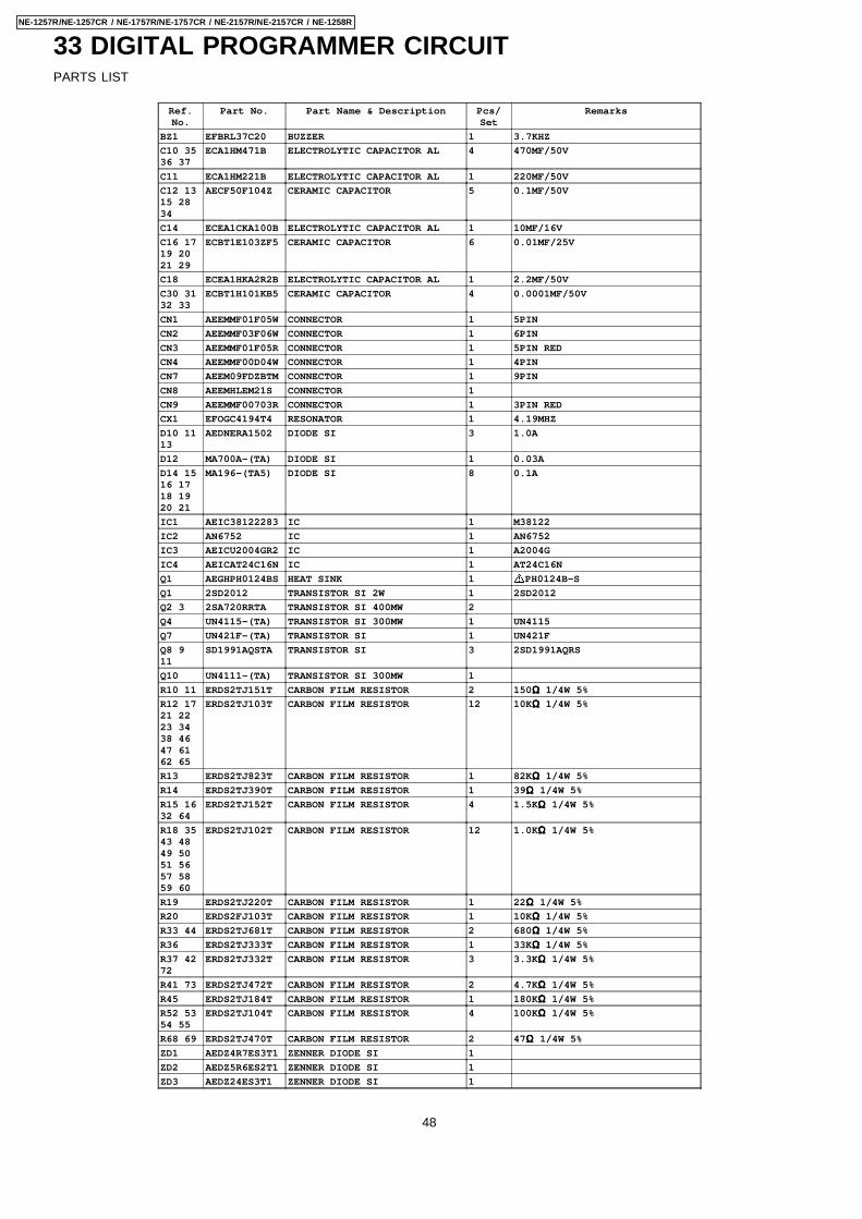
33 DIGITAL PROGRAMMER CIRCUITPARTS LIST
Ref.No.
Part No. Part Name & Description Pcs/Set
Remarks
BZ1 EFBRL37C20 BUZZER 1 3.7KHZ
C10 3536 37
ECA1HM471B ELECTROLYTIC CAPACITOR AL 4 470MF/50V
C11 ECA1HM221B ELECTROLYTIC CAPACITOR AL 1 220MF/50V
C12 1315 2834
AECF50F104Z CERAMIC CAPACITOR 5 0.1MF/50V
C14 ECEA1CKA100B ELECTROLYTIC CAPACITOR AL 1 10MF/16V
C16 1719 2021 29
ECBT1E103ZF5 CERAMIC CAPACITOR 6 0.01MF/25V
C18 ECEA1HKA2R2B ELECTROLYTIC CAPACITOR AL 1 2.2MF/50V
C30 3132 33
ECBT1H101KB5 CERAMIC CAPACITOR 4 0.0001MF/50V
CN1 AEEMMF01F05W CONNECTOR 1 5PIN
CN2 AEEMMF03F06W CONNECTOR 1 6PIN
CN3 AEEMMF01F05R CONNECTOR 1 5PIN RED
CN4 AEEMMF00D04W CONNECTOR 1 4PIN
CN7 AEEM09FDZBTM CONNECTOR 1 9PIN
CN8 AEEMHLEM21S CONNECTOR 1
CN9 AEEMMF00703R CONNECTOR 1 3PIN RED
CX1 EFOGC4194T4 RESONATOR 1 4.19MHZ
D10 1113
AEDNERA1502 DIODE SI 3 1.0A
D12 MA700A-(TA) DIODE SI 1 0.03A
D14 1516 1718 1920 21
MA196-(TA5) DIODE SI 8 0.1A
IC1 AEIC38122283 IC 1 M38122
IC2 AN6752 IC 1 AN6752
IC3 AEICU2004GR2 IC 1 A2004G
IC4 AEICAT24C16N IC 1 AT24C16N
Q1 AEGHPH0124BS HEAT SINK 1 PH0124B-S
Q1 2SD2012 TRANSISTOR SI 2W 1 2SD2012
Q2 3 2SA720RRTA TRANSISTOR SI 400MW 2
Q4 UN4115-(TA) TRANSISTOR SI 300MW 1 UN4115
Q7 UN421F-(TA) TRANSISTOR SI 1 UN421F
Q8 911
SD1991AQSTA TRANSISTOR SI 3 2SD1991AQRS
Q10 UN4111-(TA) TRANSISTOR SI 300MW 1
R10 11 ERDS2TJ151T CARBON FILM RESISTOR 2 150ΩΩΩΩ 1/4W 5%
R12 1721 2223 3438 4647 6162 65
ERDS2TJ103T CARBON FILM RESISTOR 12 10KΩΩΩΩ 1/4W 5%
R13 ERDS2TJ823T CARBON FILM RESISTOR 1 82KΩΩΩΩ 1/4W 5%
R14 ERDS2TJ390T CARBON FILM RESISTOR 1 39ΩΩΩΩ 1/4W 5%
R15 1632 64
ERDS2TJ152T CARBON FILM RESISTOR 4 1.5KΩΩΩΩ 1/4W 5%
R18 3543 4849 5051 5657 5859 60
ERDS2TJ102T CARBON FILM RESISTOR 12 1.0KΩΩΩΩ 1/4W 5%
R19 ERDS2TJ220T CARBON FILM RESISTOR 1 22ΩΩΩΩ 1/4W 5%
R20 ERDS2FJ103T CARBON FILM RESISTOR 1 10KΩΩΩΩ 1/4W 5%
R33 44 ERDS2TJ681T CARBON FILM RESISTOR 2 680ΩΩΩΩ 1/4W 5%
R36 ERDS2TJ333T CARBON FILM RESISTOR 1 33KΩΩΩΩ 1/4W 5%
R37 4272
ERDS2TJ332T CARBON FILM RESISTOR 3 3.3KΩΩΩΩ 1/4W 5%
R41 73 ERDS2TJ472T CARBON FILM RESISTOR 2 4.7KΩΩΩΩ 1/4W 5%
R45 ERDS2TJ184T CARBON FILM RESISTOR 1 180KΩΩΩΩ 1/4W 5%
R52 5354 55
ERDS2TJ104T CARBON FILM RESISTOR 4 100KΩΩΩΩ 1/4W 5%
R68 69 ERDS2TJ470T CARBON FILM RESISTOR 2 47ΩΩΩΩ 1/4W 5%
ZD1 AEDZ4R7ES3T1 ZENNER DIODE SI 1
ZD2 AEDZ5R6ES2T1 ZENNER DIODE SI 1
ZD3 AEDZ24ES3T1 ZENNER DIODE SI 1
48
NE-1257R/NE-1257CR / NE-1757R/NE-1757CR / NE-2157R/NE-2157CR / NE-1258R
Page # 4Panasonic Home Health Company
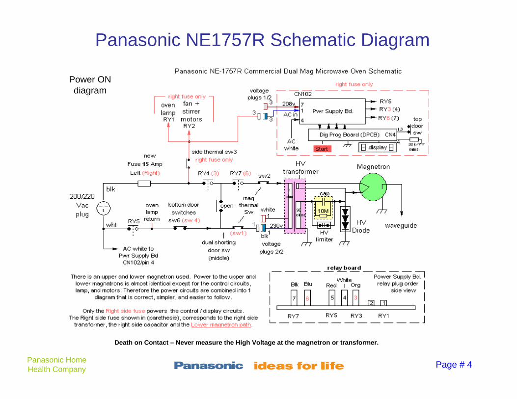
Panasonic NE1757R Schematic Diagram
Power ON diagram
Death on Contact – Never measure the High Voltage at the magnetron or transformer.
Page # 5Panasonic Home Health Company
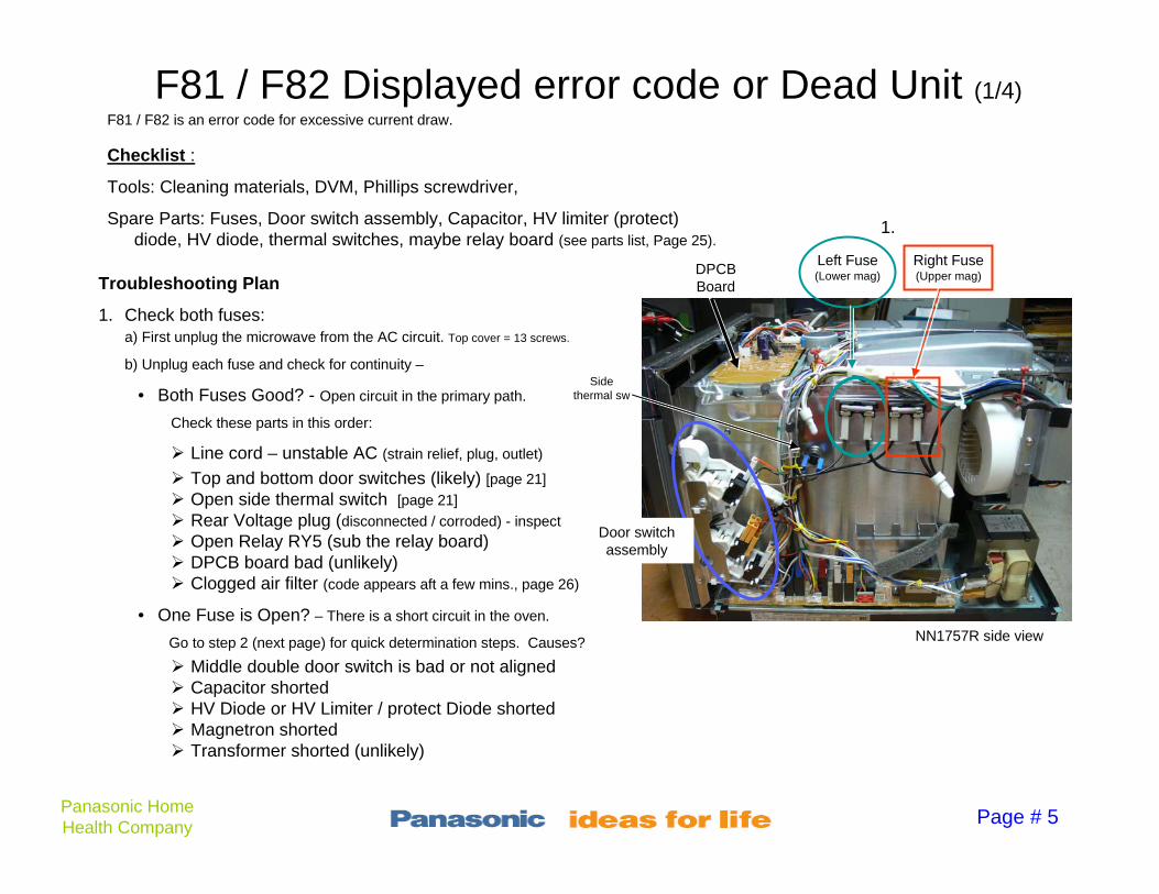
F81 / F82 Displayed error code or Dead Unit (1/4)
1. Check both fuses: a) First unplug the microwave from the AC circuit. Top cover = 13 screws.
b) Unplug each fuse and check for continuity –
• Both Fuses Good? - Open circuit in the primary path.
Check these parts in this order:
Line cord – unstable AC (strain relief, plug, outlet)
Top and bottom door switches (likely) [page 21]
Open side thermal switch [page 21]
Rear Voltage plug (disconnected / corroded) - inspect
Open Relay RY5 (sub the relay board) DPCB board bad (unlikely) Clogged air filter (code appears aft a few mins., page 26)
• One Fuse is Open? – There is a short circuit in the oven.
Go to step 2 (next page) for quick determination steps. Causes?
Middle double door switch is bad or not aligned Capacitor shorted HV Diode or HV Limiter / protect Diode shorted Magnetron shorted Transformer shorted (unlikely)
Checklist :
Tools: Cleaning materials, DVM, Phillips screwdriver,
Spare Parts: Fuses, Door switch assembly, Capacitor, HV limiter (protect) diode, HV diode, thermal switches, maybe relay board (see parts list, Page 25).
Right Fuse (Upper mag)
Left Fuse (Lower mag)DPCB
Board
1.
Door switch assembly
NN1757R side view
Troubleshooting Plan
Side thermal sw
F81 / F82 is an error code for excessive current draw.

Page # 6Panasonic Home Health Company
F81 / F82 Displayed error code or Dead Unit (2/4)
2. Disconnect both HV Transformer primary wires
(6 wires total, 3 per transformer. Both transformers).
3. Replace the open fuse. Remember which one it was.
4. Plug the unit into AC, program a time and press START. [If no response, reset on page 15.]
• Display vanishes? or / and Fuse blown again? Replace the door switch assembly.
• F81 or F82 code appears? Replace the LV transformer (relay) board and retest.
• Unit starts and counts down? Relays and Digital board are OK. - Problem is in the HV section. Unplug AC. Go to step 5.
2a. Upper mag transformer
Troubleshooting Plan
NE1757R left side
view
black
white
org
Unplug 3 primary wires
Unplug 3 primary wires
black
white
org
fuses
Relay board
2b. Lower mag transformer
NE1757R right side
view
Relays & Digital PC board Check:

Page # 7Panasonic Home Health Company
F81 / F82 Displayed error code or Dead Unit (3/4)
5. Remove AC. With a screwdriver, short across each HV diode terminals for 2 seconds to discharge the capacitor.
Place a continuity meter across the capacitor terminals (with the connectors / parts still attached). Test each capacitor, one at a time. Wait 5 sec for the reading to stabilize.
• Less than 7Meg ohms? - Replace that cap, its HV diode, and its HV limiter diode across the capacitor terminals.
• More than 7 Meg ohms? – HV diode, Magnetron, & transformer are suspect. Continue to step 6.
6. Remove the back panel.
Troubleshooting Plan
6. Rear panel
removal
Capacitor Check:
cap
dvm
5. Capacitors
HV Diode HV Diode
NE1757R side view
Page # 8Panasonic Home Health Company
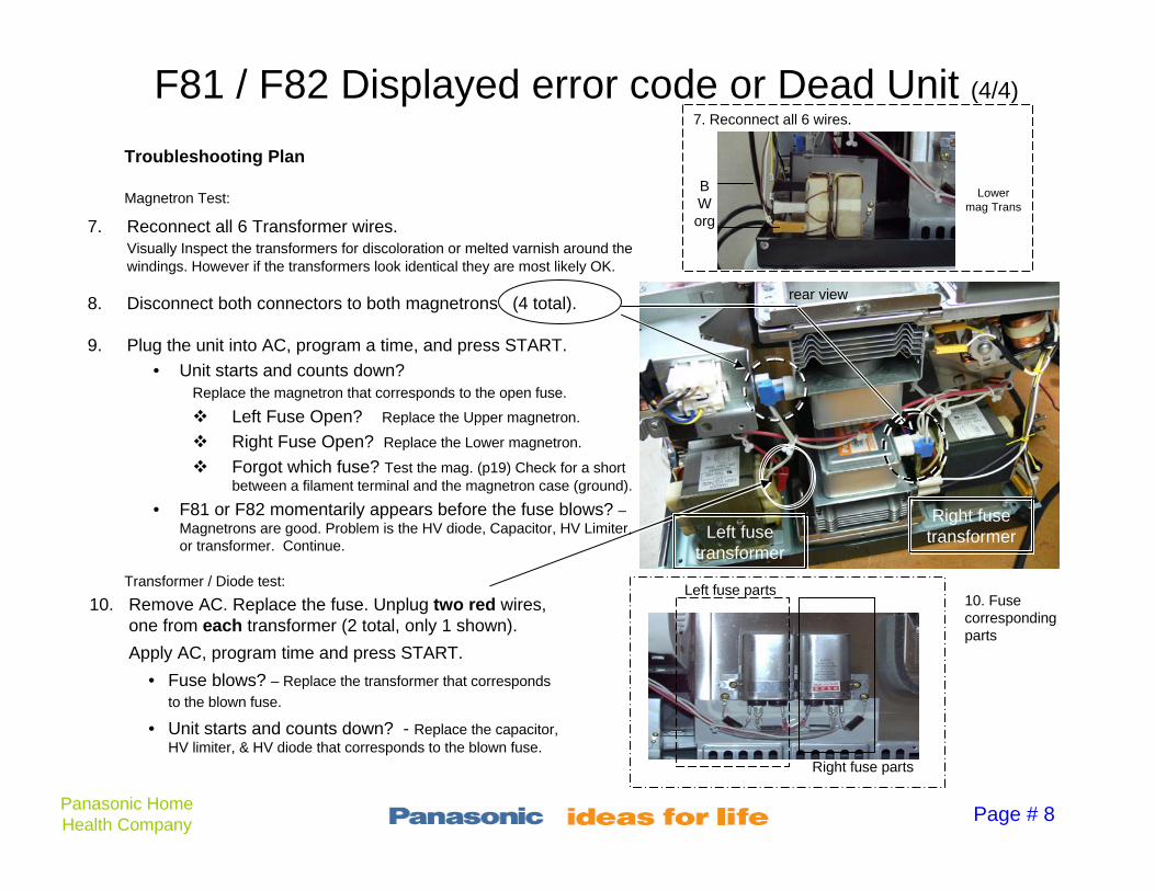
F81 / F82 Displayed error code or Dead Unit (4/4)
10. Remove AC. Replace the fuse. Unplug two red wires, one from each transformer (2 total, only 1 shown).
Apply AC, program time and press START.
• Fuse blows? – Replace the transformer that corresponds
to the blown fuse.
• Unit starts and counts down? - Replace the capacitor, HV limiter, & HV diode that corresponds to the blown fuse.
rear view
Troubleshooting Plan
Left fuse parts
Right fuse parts
7. Reconnect all 6 Transformer wires.Visually Inspect the transformers for discoloration or melted varnish around the windings. However if the transformers look identical they are most likely OK.
8. Disconnect both connectors to both magnetrons (4 total).
9. Plug the unit into AC, program a time, and press START.
• Unit starts and counts down? Replace the magnetron that corresponds to the open fuse.
Left Fuse Open? Replace the Upper magnetron.
Right Fuse Open? Replace the Lower magnetron.
Forgot which fuse? Test the mag. (p19) Check for a short between a filament terminal and the magnetron case (ground).
• F81 or F82 momentarily appears before the fuse blows? –Magnetrons are good. Problem is the HV diode, Capacitor, HV Limiter, or transformer. Continue.
Left fuse transformer
Right fuse transformer
10. Fuse corresponding parts
Magnetron Test:
Transformer / Diode test:
1.
7. Reconnect all 6 wires.
BWorg
Lower mag Trans
Page # 10Panasonic Home Health Company
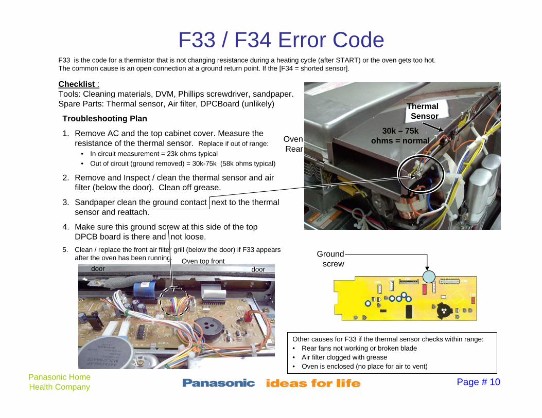
F33 / F34 Error CodeF33 is the code for a thermistor that is not changing resistance during a heating cycle (after START) or the oven gets too hot.The common cause is an open connection at a ground return point. If the [F34 = shorted sensor].
Checklist :Tools: Cleaning materials, DVM, Phillips screwdriver, sandpaper.Spare Parts: Thermal sensor, Air filter, DPCBoard (unlikely)
Troubleshooting Plan
1. Remove AC and the top cabinet cover. Measure the resistance of the thermal sensor. Replace if out of range:
• In circuit measurement = 23k ohms typical
• Out of circuit (ground removed) = 30k-75k (58k ohms typical)
2. Remove and Inspect / clean the thermal sensor and air filter (below the door). Clean off grease.
3. Sandpaper clean the ground contact next to the thermal sensor and reattach.
4. Make sure this ground screw at this side of the top DPCB board is there and not loose.
5. Clean / replace the front air filter grill (below the door) if F33 appears after the oven has been running.
Thermal Sensor
Oven Rear
30k – 75k ohms = normal
Ground screw
door doorOven top front
Other causes for F33 if the thermal sensor checks within range:• Rear fans not working or broken blade• Air filter clogged with grease• Oven is enclosed (no place for air to vent)

Page # 11Panasonic Home Health Company
F44 Error Code
Testing the membrane pad at CN7 / pins 1 & 2-9
Test between pins 1 & 2, 1 & 3, 1 & 4, etc. for a normal open circuit
F44 means the micro sees a constant press of a front panel button or there is a crack in the DPCB microprocessor board (very unlikely).
Checklist :Tools: Cleaning materials, DVM, Phillips screwdriver, Spare Parts: Membrane keypad, DPCBoard (unlikely)
Troubleshooting Plan
F44 almost always means the button membrane is damaged.
1. Remove AC and the cover.
2. Measure the resistance at the top CN7 connector between pins 1 and each one of the remaining pins.Do not press a button.
• 5k ohms or more at each pin? – Membrane is good. Inspect the DPCB board for contamination before replacing this DPCB board.
• Less than 5k ohms? – Replace the membrane pad above the door behind the metal housing.
Membrane Replacement
1. Three screws hold the top metal housing (escutcheon) from the back. Remove them and slide off the housing to expose the membrane switch.
2. Peel off the self adhesive membrane pad and replace.
Remove 3 screws
Pin 1
End Pin 9
housing screw

Page # 12Panasonic Home Health Company
F86 / F87 Error CodeF86 / F87 is a code for a missing AC Voltage at the upper or lower magnetron transformer primary winding after the start button is pressed.
Checklist :Tools: Cleaning materials, Phillips screwdriver, Spare Parts: Relay board, DPCBoard (unlikely)
Troubleshooting Plan
1. Remove AC and the cover.
2. If the code is intermittent - Remove and visually Inspect both the lower relay board and top DPCB board for cracks, signs of damage, or debris. Or just unplug and reconnect the connectors on the relay board.
3. Test the unit.
4. If the code is constant - (present every time the start button is pressed) Replace the relay board.

Page # 13Panasonic Home Health Company
F03 / F04 Error CodeF03 / F04 is a code for the wrong AC Voltage input.
Checklist :Tools: Cleaning materials, DVM, Phillips screwdriver, cup of water. Spare Parts: DPCBoard (unlikely)
Troubleshooting Plan
Concept - The AC Voltage should be measured with the oven ON if possible because of the Voltage drop from the source. At the oven,
the AC Voltage must be 208 or 230Vac + 5%.
1. Remove the top. Measure the AC Voltage between any fuse terminal and the top white connector (probe into the connector end). Place a cup of water in the oven, set a time and press start. What is the AC Voltage? Use the power on AC Voltage in step 3.
2. On the Panasonic oven, remove the rear Voltage selector cover (top picture).
3. Plug in the connector for the Voltage you measured. • 208Vac = White plug
• 230Vac = Black dot plug.
4. If the outlet AC Voltage is in-between, contact the power company. If it varies, contact an electrician.
White black (230V)
AC Volt selection plugs
socket
AC
DVM1. Measure the AC Voltage between the top white connector and one of the fuse terminals.
208Vac?
230Vac?

Page # 15Panasonic Home Health Company
Insufficient Heating 1/3
Low power can be caused by:1. Incorrect power level chosen from the keypad (e.g. defrost cycle).2. One of the two (upper or lower magnetron) heating units not working3. Insufficient AC input Voltage during operation
Checklist :Tools: Cleaning materials, DVM, Clamp-On Ammeter, Phillips screwdriver, 8oz cup of water. Spare Parts: Thermal cutout, HV Diode, Capacitor, A stirrer motor (unlikely)
Water not boiling?If the water is not boiling, one magnetron circuit is defective. Next you will Monitor the current consumed by each transformer one at a time, to see if they are equal. You will need a clamp on ammeter.
Heat Test – Do this first.
1. Program the microwave for full power (level 10 – see pictures at right).
2. Fill an 8 oz. cup with room temperature tap water (see the bottom of plastic cups for capacity number in ounces.).
3. Program the time for 1 minute + 35 seconds and press START.
Water Boiling?If the oven can heat an 8 oz cup of water to boiling (212 degrees F / 100C), when set at power level 10 (max), the oven is generating the correct heating power. There is nothing wrong with the microwave oven.
[Technically the oven must raise that much water 140 degrees F in that period of time.]
Program:
Unlock the unit
1. Open Door
2. Hold STOP first then press and hold the PROG button until “P” appears in the display. (now is unlocked for manual time entry)
Program Time & Start
1. Press the POWER LEVEL button once (or repeatedly) until HIGH is displayed.
2. Insert the desired heat time (e.g. 1, 3, 5 for 1 min, 35 sec.).
3. Place H2O in the oven and close the door.
4. Press START to run.
Return to Previous program
1. Close the door wait for the display to be blank (blank means no zero number).
2. Hold PROG button until “P L” are displayed.
Death on Contact – Never measure the High Voltage at the magnetron or transformer.

Page # 16Panasonic Home Health Company
Insufficient Heating (con’t) 2/3
Top stirrerBottom stirrer
Lift Bottom plate up
using side access hole
Bottom oven plate Side access hole
Orange connector (do not unplug)
1. Place clamp on ammeter around both Orange connector wires.1. Place a clamp-on ammeter around both wires of the orange
connector of one transformer. Place water in the oven. Program in a time and press START. Stop when the ammeter reading stabilizes. Note the reading.
2. Turn off the microwave (open the door). Move the clamp-on ammeter to the other transformer’s orange connector wires. Leave water in the oven. Program in a time and press START. Stop when the reading stabilizes. Note the reading.
• Both readings 6-7 Amps AC? – Normal. Electronically the magnetrons are drawing the correct amount of power.
o See if both stirrers are rotating [Top – remove shield. See page 26. Bottom - lift the bottom plate by placing a screwdriver in the special right side access hole and gently levering the bottom plate upward to expose the bottom stirrer.
o Check bottom air filter & clean (details page 26).
o Check Thermal temp sensor (page 10)
• One reading is 0 or Less than 5 Amps AC? - One of the magnetrons is not applied power. Proceed to step 3. Suspects ?
o A thermal cutout switch (open), [page 21]
o HV diode (open), [page 19]
o Capacitor (low capacity), [page 20]
o Weak magnetron or open filament. [page 22]
Investigation:
Top stirrer
Clamp ammeter
White wires

Page # 17Panasonic Home Health Company
Insufficient Heating (con’t) 3/3
3. How low is the ammeter reading?
• 0 Amps ? – There is an open in one of the magnetron circuits. Which transformer? Check the corresponding parts:
• Right transformer – suspect just the Lower Magnetron, lower thermal sensor, right side capacitor and diodes.
• Left transformer – suspect just the Upper Magnetron, upper thermal sensor, Left side capacitor and diodes.
Test the magnetron (page 22). Tests good?
Replace the cap and diodes.
• 1 - 5 Amps AC? - One of the magnetrons is weak or the one Capacitor + Diodes is defective.
Remove the white cap wire and diode wire from one cap and place it on the other one. [Interchange the diode and wire.] Note they are mirror images of the other. Measure the current again with the transformer with the low reading.
o 6-7 Amps now? Replace the magnetron.
o Still 1-5 Amps now? Replace the cap + HV and limiter/protect diodes that corresponds to the low Amp reading transformer.
Right Trans, Lower Mag & Sw
Remaining Lower Mag Parts Right side Cap & Diodes
Right transformer Right cap
Left transformer Left cap
Page # 19Panasonic Home Health Company
Diode Testing (unplug from AC)
cap
dvm
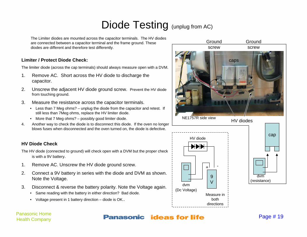
Limiter / Protect Diode Check:
The limiter diode (across the cap terminals) should always measure open with a DVM.
1. Remove AC. Short across the HV diode to discharge the capacitor.
2. Unscrew the adjacent HV diode ground screw. Prevent the HV diode from touching ground.
3. Measure the resistance across the capacitor terminals.• Less than 7 Meg ohms? – unplug the diode from the capacitor and retest. If
still less than 7Meg ohms, replace the HV limiter diode.
• More that 7 Meg ohms? – possibly good limiter diode.
4. Another way to check the diode is to disconnect this diode. If the oven no longer blows fuses when disconnected and the oven turned on, the diode is defective.
HV Diode Check
The HV diode (connected to ground) will check open with a DVM but the proper check
is with a 9V battery.
1. Remove AC. Unscrew the HV diode ground screw.
2. Connect a 9V battery in series with the diode and DVM as shown. Note the Voltage.
3. Disconnect & reverse the battery polarity. Note the Voltage again.• Same reading with the battery in either direction? Bad diode.
• Voltage present in 1 battery direction – diode is OK..
caps
NE1757R side viewHV diodes
(resistance)9V
HV diode
dvm(Dc Voltage)
+ -
Measure in both
directions
Ground screw
Ground screw
The Limiter diodes are mounted across the capacitor terminals. The HV diodes are connected between a capacitor terminal and the frame ground. These diodes are different and therefore test differently.

Page # 20Panasonic Home Health Company
Capacitor Testing (unplug from AC)
Capacitor Check:
1. Momentarily short across the HV diode wires to discharge the capacitors (prevents DVM damage).
2. Disconnect one of the capacitor connectors.
3. Measure the resistance across the capacitor. Read after 10 sec.
• Resistance is 7Meg ohms or greater? Normal. Cap is not shorted.
• Resistance is less than 7Meg? - Normal. The capacitor is not shorted.
cap
dvm
caps
NN1757R side viewHV diodes
(resistance)
Page # 21Panasonic Home Health Company
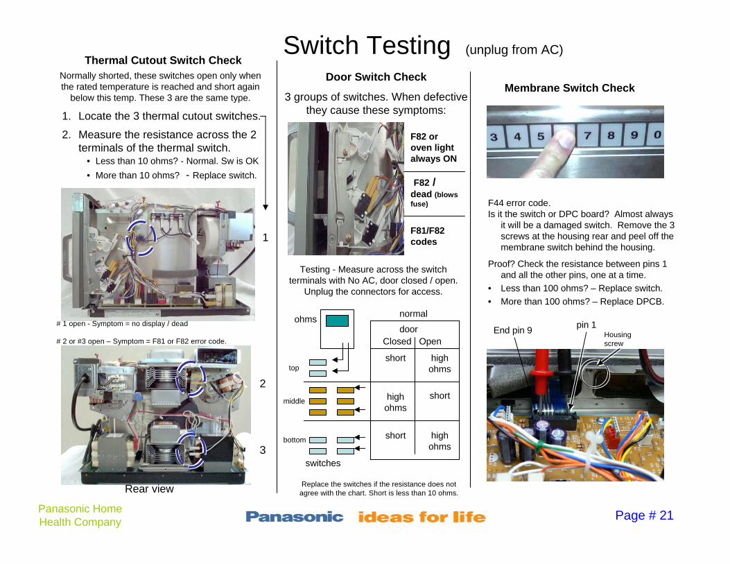
Switch Testing (unplug from AC)Thermal Cutout Switch Check
1. Locate the 3 thermal cutout switches.
2. Measure the resistance across the 2 terminals of the thermal switch.
• Less than 10 ohms? - Normal. Sw is OK
• More than 10 ohms? - Replace switch.
Door Switch Check
3 groups of switches. When defective they cause these symptoms:
1
# 1 open - Symptom = no display / dead
Rear view
2
3
# 2 or #3 open – Symptom = F81 or F82 error code.
Testing - Measure across the switch terminals with No AC, door closed / open.
Unplug the connectors for access.
Closed Opendoor
short
high ohms
short
short high ohms
high ohms
Normally shorted, these switches open only when the rated temperature is reached and short again
below this temp. These 3 are the same type.
normal
Membrane Switch Check
F44 error code. Is it the switch or DPC board? Almost always
it will be a damaged switch. Remove the 3 screws at the housing rear and peel off the membrane switch behind the housing.
Proof? Check the resistance between pins 1 and all the other pins, one at a time.
• Less than 100 ohms? – Replace switch.
• More than 100 ohms? – Replace DPCB.
End pin 9pin 1
Housing screw
ohms
top
middle
bottom
switches
Replace the switches if the resistance does not agree with the chart. Short is less than 10 ohms.
F82 / dead (blows fuse)
F82 or oven light always ON
F81/F82 codes

Page # 22Panasonic Home Health Company
Magnetron Tests (unplug from AC)
Both tests can be made after removing 1 filament lead and testing with an ohmmeter.
Filament Test
1. Remove one or both filament leads (from F or FA terminals)
2. Place an ohmmeter across the two magnetron terminals shown as F and FA in the diagram.
• No Reading is displayed? – Filament is open. Replace the magnetron.
• Reading is 0 ohms? – Normal. Continue.
Short test
3. Place the ohmmeter leads across one of the filament leads and the case.
• Reading is 0 ohms? – Defective. Replace this magnetron that is blowing out the fuse.
• No Reading is displayed? – Normal. Magnetron is not shorted / not blowing out fuses.
1. Remove either wire (both shown removed
from magnetron for clarity)

Page # 24Panasonic Home Health Company
Model and Date Code Location
December 2006
Serial number date code at the 3rd & 4th digit:
X A D 6 1 8 9 5 4 8 94
Month Year
Parts NOT covered under the 3 year parts, labor, and magnetron warranty:
• Air filter (screw located under the door)
• Oven Light bulb (remove top cover)
• Plastic Ceiling plate / splatter shield
(resultant damaged parts not covered = warranty is void if the shield is missing)
• Use of metal pans
• Ceramic bottom plate
• Customer Abuse
date= 2006
1-9 = month0 = OctN = NovD = Dec

Page # 25Panasonic Home Health Company
Model NE1757R Common Parts List
A400b-3280
(No warranty)
Metal Air Filter (43) (below door)A390L-3500Door Assembly
ANE010T8U0AP
(No warranty)
Shelf / Floor Plate (5)A621B3660APHV Transformer (77)
A2011-3470
Warranty Void if missing
Splatter Shield / Ceiling plate (33)
ANE61458U0APMagnetron Thermal Switch / Cutout (57)
2M210-M1F1Magnetron (109)ANE61458U0APSide Thermal Switch / Cutout (70)
A61443660AP
A6144-3280
Stirrer Motor - Upper (68)
Stirrer motor - Lower (65)
A606V3960AP (left side)
A606W3960AP (right side)
HV Limiter / Protect (W4) longer red wire
HV Limiter / Protect (W5) shorter red wire
B692m3660APRelay Board (82) (LV transformer Bd.)
A62023960apHV Diode (76)
B900C3660AP
(No warranty)
AC Cord (90)A60903660AP (replacement may have a higher Voltage than original)
Capacitor (61)Comes w 2 new fuses
A60304080BP
(No warranty)
Oven Lamp (55)A64793310QP3 screws to access. Peel off membrane strip
Pushbutton Membrane (E3)
A62303970AP (two fuses come with the cap)
Fuse = 15 Amp (79)Original may be 18A. Change to 15A
A393C-3470Door Switch Assembly (complete)
Part NumberDescriptionPart NumberDescription
Note - These are the part numbers only for the above model NE1757R microwave.

Page # 26Panasonic Home Health Company
Splatter Shield & Air Filter Check
Splatter Shield Removal
Procedure:
1. Push both the left and right plastic tab toward the sides of the oven cavity. (only left side pictured)
2. The plastic splatter shield will drop down to expose the top stirrer.
3. Warranty is Void if the oven is operated without the food splatter shield.
Push in
Air Filter Removal
Procedure:
1. Open the door to access the air filter screw at the right of the metal air filter grill.
2. Remove the screw and grill for cleaning.
screwAir Filter grill

Panasonic
Number: E10-2010-05 Technical Bulletin Date: July, 2010
Panasonic Home and Health Company Home Appliance Group / Food service
Product: Commercial Mircowave Oven
Model: NE1258R NE1257R NE1757R
NE2157R NE2180 NE3280
Subject: Capacitor replacement in PRO 1 and PRO 2 units
When replacing a defective (shorted) capacitor on any the aforementioned models above, please follow the guidelines below.
1. Check to see if any of the other installed capacitors are either China production or Japan
(Matsushita) production. See illustration below. 2. If the other Capacitors are China production, check the working voltage (VAC) of the capacitors. It
should be 2300VAC for the PRO 1 units and 2500 VAC for the Pro 2 units. Please refer to the chart below.
3. If the capacitor is not at the new proper rated voltage, replace them with the improved one even if it measures good as this will prevent additional service calls.
Additionally, if the model number is NE1757R or NE2157R, please make sure to replace the 18 or 20 Amp fuse with the new 15 Amp fuse* which are supplied with the capacitor.
*When submitting the warranty claim, please do not charge for the 15 Amp fuses as there are included with the kit.
The Dates below indicate when the new capacitors (higher VAC ) were installed
MODEL OLD NEW DATE EFFECTIVE ORIGINAL PART NO. NEW PART NO.
NE1257R 2100 V AC 2300 V AC 9/10/2009 A60903650AP
NE1258R 2100 V AC 2300 V AC 9/10/2009 A60903650AP
NE1757R 2100 V AC 2300 V AC 9/10/2009 A60903660AP A60903660APS
NE2157R 2100 V AC 2300 V AC 5/15/2006 A60903780AP
NE2180 2300 V AC 2500 V AC 12/4/2009 A60903050GP
NE3280 2300 V AC 2500 V AC 11/5/2009 A63903330GP A63903A41AP

Panasonic
Number: E10-2010-06 Technical Bulletin Date: July, 2010
Panasonic Home and Health Company Home Appliance Group / Food service
Product: Commercial Mircowave Oven
Model: NE1257R, NE1258R, NE1757R,
NE2157R, NE2180, NE3280
Subject: Magnetron Test for Opens, shorts or Insufficient Power A. The following tests will indicate if a magnetron is open or shorted.
• Unplug the unit • Discharge all the H.V Capacitors (refer to service manual on how to discharge) • Disconnect all the leads (connectors) from the magnetron terminals.
B. The following temperature test will indicate if a magnetron is weak. Make sure unit is plugged in.
1. Fill a beaker or cup with EXACTLY 8 oz (1 Cup) tap water. 2. Record the temperature of the water (Should be approx. 70o F) 3. Place it in the center of the microwave and heat it for the time specified*. 4. Water should be boiling. Record the temperature again. 5. Temperature should rise approximately 142o F (Go to Step 6 only if temperature rise is
considerably lower than 142o F otherwise all magnetrons are functioning properly) 6. To test for the weak magnetron, connect one magnetron at a time and repeat Steps 1-4. a. For ovens that contain 2 magnetrons (NE1257R, NE1258R, NE1757R, NE2157R), the
temperature rise should be approximately 70o F per magnetron.
b.For ovens that contain 4 magnetrons (NE2180, NE3280), the temperature rise should be
approximately 35o F per magnetron. * See field expedient test on the back of the page
Step 1 • Using an Ohm meter on its lowest resistance scale, measure the
resistance from one magnetron terminal to the other in either direction as shown on the illustration on the left.
• Meter should read less than 1Ω indicating that the filament is good. • If Filament checks good, proceed to Step 2
Step 2 • Using an Ohm meter on its highest resistance scale, measure the
resistance from one of the magnetron terminals to the metal casing of the magnetron as shown on the illustration on the left.
• Meter should read infinity (open circuit) regardless of meter polarity. If the meter indicates a short (Less than 1 Ω), the magnetron is defective.

Panasonic
Field Expedient Power Determination Tests: • All times calculated using water starting at 70°F 21°C brought to 212°F 100°C. • Times given below should serve as the benchmark. If oven cannot bring vessel to a boil within
the time given, (on High” Power) call for Service Information TOLL FREE @ 877-CMO-OVEN
MODEL AMOUNT OF
WATER: VESSEL: TIME:
NE-1257/8 1 CUP PYREX MEASURE 2:15
NE-1757 1 CUP PYREX MEASURE 1:35
NE-2157 1 CUP PYREX MEASURE 0:54
NE-2180 1 CUP PYREX MEASURE 0:54
NE-3280 1 CUP PYREX MEASURE 0:40 *Inside of the oven should be relatively clean *Remove Metal Rack(s) for this test

Panasonic Consumer Electronics Company
Panasonic Service Bulletin Date: JUNE 2000 Number: NE0006-1757 Revised – June 2007 Product: Commercial Microwave Oven Model(s): NE1057, NE1257, NE1257A,
NE1257R, NE1258A, NE1258R, NE1457, NE1757, NE1757A, NE1757R, NE2157A, NE2157R
Place this Service Bulletin with respective Service Manuals
®
A393C-3470
NE1257 NE1257A NE1257R NE1258A NE1258R NE1757
NE1757A NE1757R NE2157A NE2157R
NE1057 NE1457
The parts shown below are now available as a complete assembly for the models listed above. When placing an order for this assembly (referred to as a “Latch Switch Assembly”), use part number A393C-3470.
Please note that all individual components shown above are also available.
WARNING! This Service Bulletin is designed for experienced repair technicians only and is not designed for use by the general public. It does not contain warnings or cautions to advice non-technical individuals of potential dangers in attempting to service a product. Products powered by electricity should be serviced by experienced professional technicians. Any attempt to service or repair the product or products dealt with in this Service Bulletin by anyone else could result in serious injury or death. © 2007 Panasonic. All rights reserved. Unauthorized copying and distribution is a violation of law.

PANASONIC Consumer Electronics Company
Panasonic Service Bulletin Date: March 2007 Number: NE9903-1757 Product: Commercial Microwave Oven Model(s): NE1057, NE1257, NE1258, NE1457,
NE1757, NE2157
Place this Service Bulletin with respective Service Manuals
®
WARNING! This Service Bulletin is designed for experienced repair technicians only and is not designed for use by the general public. It does not contain warnings or cautions to advice non-technical individuals of potential dangers in attempting to service a product. Products powered by electricity should be serviced by experienced professional technicians. Any attempt to service or repair the product or products dealt with in this Service Bulletin by anyone else could result in serious injury or death. © 2007 Panasonic. All rights reserved. Unauthorized copying and distribution is a violation of law.
The door for the Microwave Oven models listed below is available as a complete assembly.
Please note that all individual parts for these doors will continue to be available.
Model Number Door Assembly NE1057 NE1257 (A, R) NE1258 (A, R) NE1457 NE1757 (A, R) NE2157 (A, R)
A390L-3500

Panasonic
Number: E10-03-06R
Technical Bulletin
Date: June, 2003
Panasonic Consumer Electronics Company Enterprise Sales Group
Product: Commercial Mircowave Oven
Model: NE1257R, NE1258R, NE1757R
Subject: In order to enhance the oven’s performace, door hook “A” has been modified. All ovens manufactured after December 2002 already have the modified door hook “A” installed and are not subject to this bulletin. Symptom: The oven’s cavity light and the display will function. The timer can be set, but the oven will not start after the START button is pressed. Cause: Excessive force applied while closing the door causes the plastic elements of the door hook “A”, which limit the movement of levers, to break and subsequently disallow for proper operation of switches. Remedy: Install new (modified) door hook “A”, part number: A3020-3850. NOTE: Since the existing and the improved door hooks have the same part number, please refer to figures below for proper identification of the improved door hook.
Additional Wedges Added for Strength