Embed Size (px)
Citation preview
SPECIFICATION
ORDER PICKER
EOP68
Introduction
In order to meet the needs of the national environmental protection request, To
reduce industrial pollution and improve productivity, we develop new series of
EOP68 Type High level order picker . on the basis of absorption of the advantages
of domestic & overseas battery order picker, they are especially suitable for cargo
loading and unloading, handling, stacking, etc. for food, bank, light textile, station,
port, logistics and other enterprises.
The order picker adopts advanced structures such as EPS steering system, new AC
controller. It is equipped with high-quality motor, traction battery and high-power
pumping station motor. Therefore, it has the characteristics of superior
performance, convenient operation, wide field of view, flexible steering, reliable
braking, good power, low noise, no pollution, and beautiful appearance.
This manual describes the technical parameters of the order picker, working
principle and operation, maintenance, and other aspects. It can help operators use
the order picker more reasonable, make its maximum effect.
It is hoped that Operator strictly abide the regulations and the precautions in this
manual when using the order picker .Carefully use them so that your order picker
can be in the best working condition for long period of time to maximize its
effectiveness. And create better economic benefits.
The Statement
Our company production model EOP68 type high level order picker is a special
motor vehicle used in factory ,tourist attractions ,amusement places which is
specified by “special equipment safety supervision regulations” .
Contents
1.The General Introduction............................................................................................. 1
2.Proper usage ..................................................................................................................... 2
3.Introduction of the product ......................................................................................... 3
3.1Overview of main components ........................................................................................ 3
3.2Truck schematic diagram & Model parameters ...................................................... 4
3.3Safe operation and warning labels ................................................................................. 7
3.4Name plate ............................................................................................................................. 8
4.Safety Caution ................................................................................................................... 8
5.Test run,Transportation,Outage ............................................................................. 10
5.1Test run ................................................................................................................................. 10
5.2Lifting & Transportation ................................................................................................... 10
5.3Outage ...................................................................................................................................... 11
6.Routine Inspection ...................................................................................................... 11
7.The Schematic diagram of Operating Mechanism ............................................ 11
8Operating specification ............................................................................................... 14
8.1Parking .................................................................................................................................... 14
8.2Loading capacity graph ..................................................................................................... 14
8.3Lifting up/Lowering down .............................................................................................. 15
8.4Traveling ................................................................................................................................. 16
8.5Steering ................................................................................................................................. 17
8.6Monitor ................................................................................................................................. 18
8.7Braking .................................................................................................................................... 19
8.8Brake structure &Brake Schematic .............................................................................. 20
8.9Trouble .................................................................................................................................... 20
8.10Emergency situations ...................................................................................................... 20
9Changing and Replacement for battery ................................................................. 21
9.1Replacement ....................................................................................................................... 22
9.2Charging ................................................................................................................................ 23
10.Maintain Introduction ....................................................................................................... 23
10.1Maintenance list ................................................................................................................ 24
10.2Lubrication point .............................................................................................................. 25
10.3Check and refill hydraulic oil ....................................................................................... 25
10.4Check the electrical fuse ................................................................................................. 26
10.5 Remove and reinstall the shield ................................................................................. 26
11.Trouble shooting ..................................................................................................... 27
12.After-sales service ..................................................................................................... 28
13.Electrical Schematic diagram .................................................................................... 29
14.Hydraulic Schematic diagram ............................................................................... 30
1
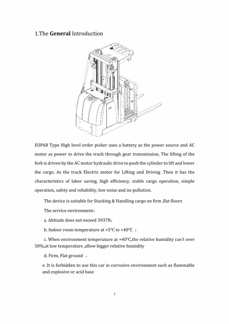
1.The General Introduction
EOP68 Type High level order picker uses a battery as the power source and AC
motor as power to drive the truck through gear transmission, The lifting of the
fork is driven by the AC motor hydraulic drive to push the cylinder to lift and lower
the cargo. As the truck Electric motor for Lifting and Driving .Then it has the
characteristics of labor saving, high efficiency, stable cargo operation, simple
operation, safety and reliability, low noise and no pollution.
The device is suitable for Stacking & Handling cargo on firm ,flat floors
The service environment:
a. Altitude does not exceed 3937ft;
b. Indoor room temperature at +5℃ to +40℃ ;
c. When environment temperature at +40℃,the relative humidity can’t over
50%,at low temperature ,allow bigger relative humidity
d. Firm, Flat ground 。
e. It is forbidden to use this car in corrosive environment such as flammable
and explosive or acid base
2
2. Proper use
Please using the High-level order picker according to this specification.
This is a stand on type High level order picker with autonomous control ,
lifting and lowering is controlled by the handle button.
Improper use can cause personal injury or machine damage. Operators or
operating companies need to ensure proper using,
The Truck needs to be used on a firm ,flat ,intact surface and suitable
surface ;the truck is designed for indoor use at room temperature from+5°C to
+40°C
Use under light load without using permanent barriers or pits ,It is
forbidden to operate on the slopes .During Operation ,The goods must be placed
approximately at the center of the truck’s load center
Lifting or Carrying people is strictly prohibited ,If carried goods .The goods
must fall on the lifting point 。
It is prohibited to use this truck on lifting or loading ramps.
The rated capacity is marked on the capacity label or nameplate. And the
operator must pay attention to the warming signs and safety instructions.
Operating lighting must be at least 50LUX
Modification
Any modification that may affect the truck rated capacity, stability or safety
operations must be approved in advance by the Truck’s original manufacturer or
Its authorized Manufacturer or its successor. This includes the effects of changes
such as Braking ,steering ,visibility, and the addition of removable accessories.
After the manufacturer or its successor approves the modification or change ,the
capacity name plate ,Label, identification marks, operation and maintenance
manual must be changed accordingly
Truck damage caused by not following Instruction will lose its warranty.
3
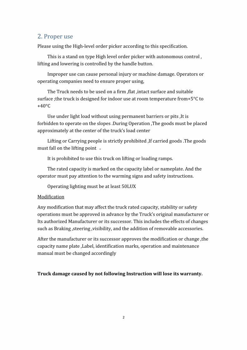
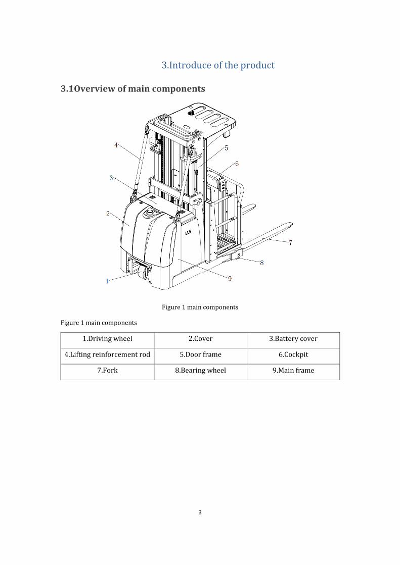
3.Introduce of the product
3.1Overview of main components
Figure 1 main components
Figure 1 main components
1.Driving wheel 2.Cover 3.Battery cover
4.Lifting reinforcement rod 5.Door frame 6.Cockpit
7.Fork 8.Bearing wheel 9.Main frame
4
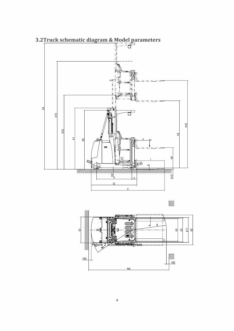
3.2Truck schematic diagram & Model parameters
Figure 2 Schematic diagram
5
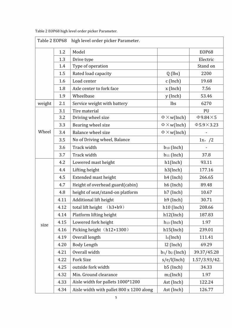
Table 2 EOP68 high level order picker Parameter.
Table 2 EOP68 high level order picker Parameter.
1.2 Model EOP68
1.3 Drive type Electric
1.4 Type of operation Stand on
1.5 Rated load capacity Q (lbs) 2200
1.6 Load center c (Inch) 19.68
1.8 Axle center to fork face x (Inch) 7.56
1.9 Wheelbase y (Inch) 53.46
weight 2.1 Service weight with battery lbs 6270
Wheel
3.1 Tire material
PU
3.2 Driving wheel size Φ×w(Inch) Φ9.84×5
3.3 Bearing wheel size Φ×w(Inch) Φ5.9×3.23
3.4 Balance wheel size Φ×w(Inch) -
3.5 No of Driving wheel, Balance
wheel/Bearing wheel(X=Driving wheel 1x,/2
3.6 Track width b10 (Inch) -
3.7 Track width b11 (Inch) 37.8
size
4.2 Lowered mast height h1(Inch) 93.11
4.4 Lifting height h3(Inch) 177.16
4.5 Extended mast height h4 (Inch) 266.65
4.7 Height of overhead guard(cabin) h6 (Inch) 89.48
4.8 height of seat/stand-on platform h7 (Inch) 10.67
4.11 Additional lift height h9 (Inch) 30.71
4.12 total lift height (h3+h9) h10 (Inch) 208.66
4.14 Platform lifting height h12(Inch) 187.83
4.15 Lowered fork height h13 (Inch) 1.97
4.16 Picking height(h12+1300) h15(Inch) 239.01
4.19 Overall length l1(Inch) 111.41
4.20 Body Length l2 (Inch) 69.29
4.21 Overall width b1/ b2 (Inch) 39.37/45.28
4.22 Fork Size s/e/l(Inch) 1.57/3.93/42.
13 4.25 outside fork width b5 (Inch) 34.33
4.32 Min. Ground clearance m2(Inch) 1.97
4.33 Aisle width for pallets 1000*1200
crossways Ast (Inch) 122.24
4.34 Aisle width with pallet 800 x 1200 along
forks
Ast (Inch) 126.77
6
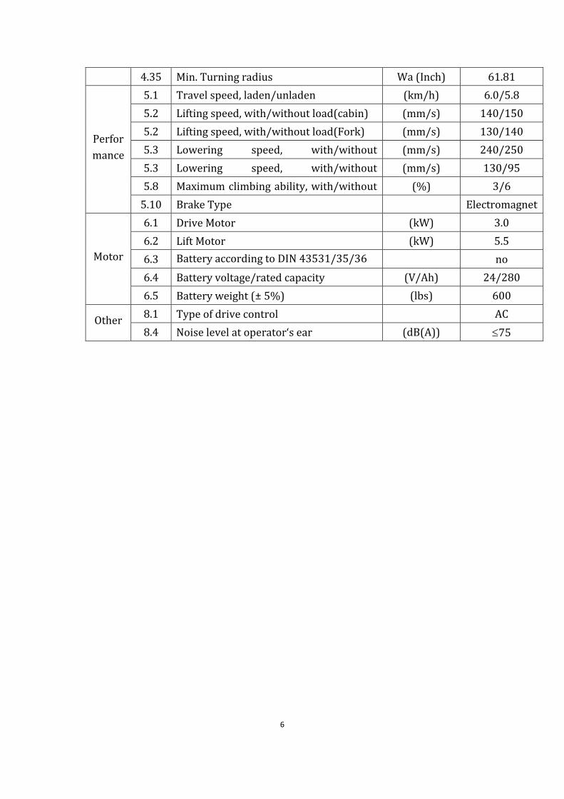
4.35 Min. Turning radius Wa (Inch) 61.81
Perfor
mance
5.1 Travel speed, laden/unladen (km/h) 6.0/5.8
5.2 Lifting speed, with/without load(cabin) (mm/s) 140/150
5.2 Lifting speed, with/without load(Fork) (mm/s) 130/140
5.3 Lowering speed, with/without
load(cabin)
(mm/s) 240/250
5.3 Lowering speed, with/without
load(Fork)
(mm/s) 130/95
5.8 Maximum climbing ability, with/without
load
(%) 3/6
5.10 Brake Type Electromagnet
ic
Motor
6.1 Drive Motor (kW) 3.0
6.2 Lift Motor (kW) 5.5
6.3 Battery according to DIN 43531/35/36
A,B,C,no no
6.4 Battery voltage/rated capacity (V/Ah) 24/280
6.5 Battery weight (± 5%) (lbs) 600
Other 8.1 Type of drive control AC
8.4 Noise level at operator‘s ear (dB(A)) 75
7
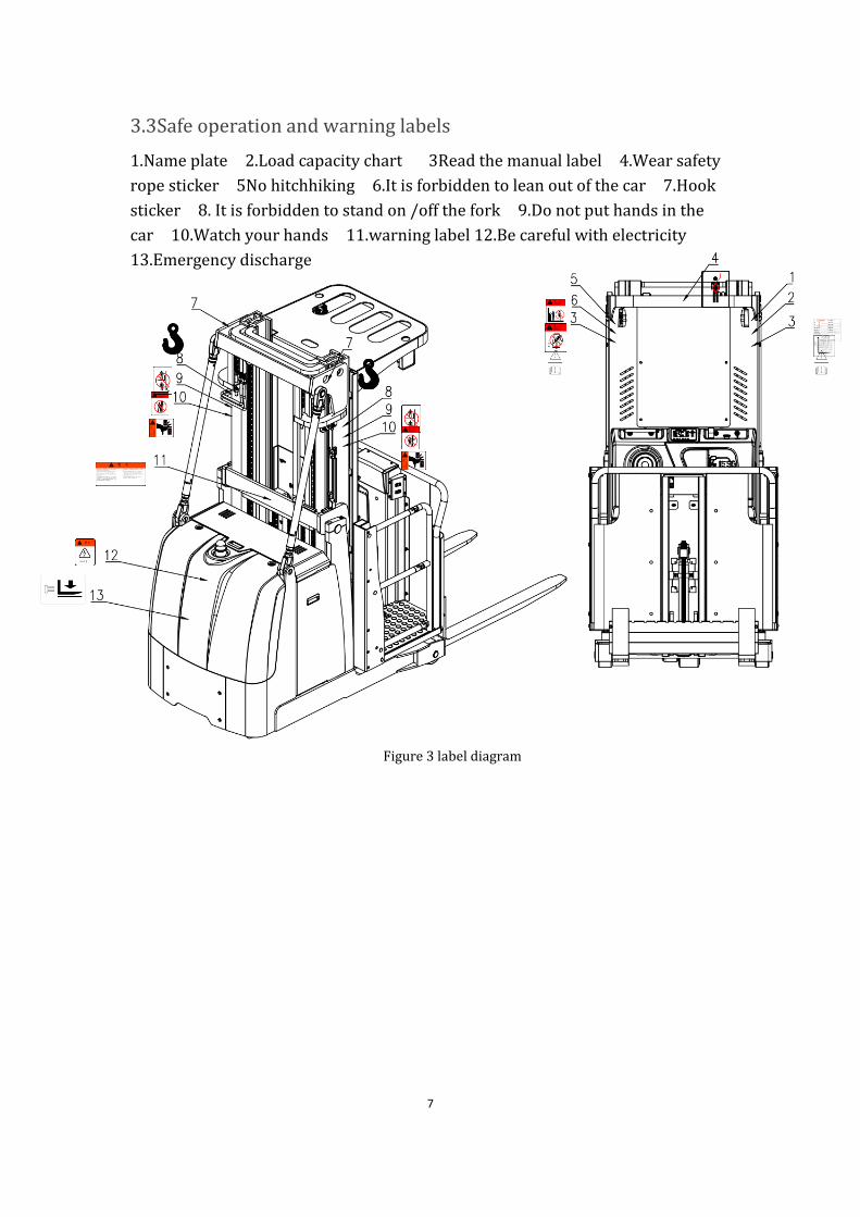
3.3Safe operation and warning labels
1.Name plate 2.Load capacity chart 3Read the manual label 4.Wear safety
rope sticker 5No hitchhiking 6.It is forbidden to lean out of the car 7.Hook
sticker 8. It is forbidden to stand on /off the fork 9.Do not put hands in the
car 10.Watch your hands 11.warning label 12.Be careful with electricity
13.Emergency discharge
Figure 3 label diagram
述
8
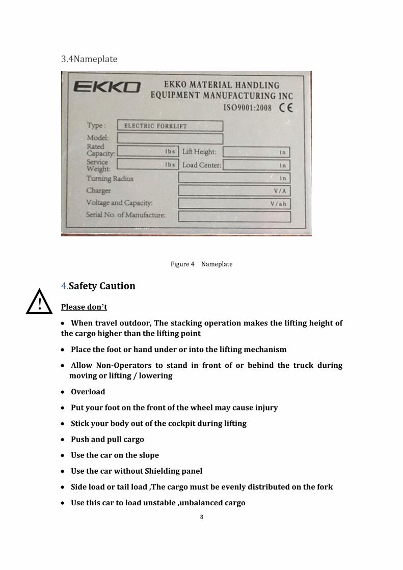
3.4Nameplate
Figure 4 Nameplate
4.Safety Caution
Please don’t
• When travel outdoor, The stacking operation makes the lifting height of
the cargo higher than the lifting point
• Place the foot or hand under or into the lifting mechanism
• Allow Non-Operators to stand in front of or behind the truck during
moving or lifting / lowering
• Overload
• Put your foot on the front of the wheel may cause injury
• Stick your body out of the cockpit during lifting
• Push and pull cargo
• Use the car on the slope
• Use the car without Shielding panel
• Side load or tail load ,The cargo must be evenly distributed on the fork
• Use this car to load unstable ,unbalanced cargo
!
9
• Use this car without the manufacturer’s written consent
Observing different ground condition during driving .The cargo may fall down, or the
car may lose control ,Please check the loading situation frequently, If the cargo becomes
unstable .Stop the operation of the truck immediately . When the cargo slide or slide off
the truck, Stop the car by pressing emergency stop switch .Please refer to Chapter 6 for
any truck Trouble .Maintain according to regular inspection. The forklift is not waterproof,
Please use it in dry environment. Continuous operation for a long time may damage the
power box ,please stop operating when Hydraulic oil temperature is too high .
• The operator should put on safety shoes when operating the forklift
• The car is suitable for indoor use in temperature from +5°C to 40°C
• Operating lighting must be at least 50LUX
• Don’t use the car on the slope
• The uplifted cargo will become unstable because of wind .Don’t lift the
cargo in windy condition
• In order to prevent sudden movement of the car when the car is not
operated (such as caused by others),turn off the car power and remove the
key when not operating
!
10
5.Test run, Transportation, Outage
5.1Test run Table 3 test data
Model EOP68
Packing weight(lbs) 6270
Lifting height(Inch) 177.16
Size(Inch) 113*49.21*98.43
After receiving our new forklift or when it needs to be retest please with process
with following steps before (the first )operation of the forklift :
• Check if all parts are included .and there is no damage
• Battery installation and charging (refer to Chapter 9)
• Carry out daily inspection and machine function inspection
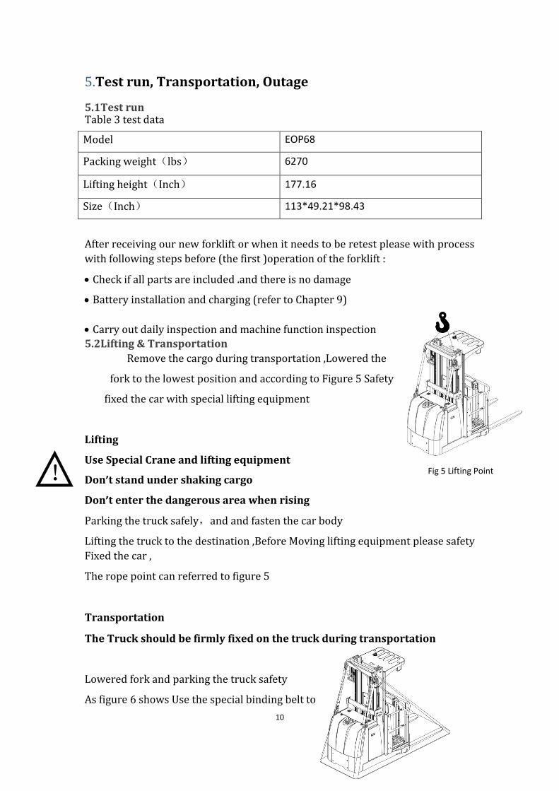
5.2Lifting & Transportation
Remove the cargo during transportation ,Lowered the
fork to the lowest position and according to Figure 5 Safety
fixed the car with special lifting equipment
Lifting
Use Special Crane and lifting equipment
Don’t stand under shaking cargo
Don’t enter the dangerous area when rising
Parking the truck safely,and and fasten the car body
Lifting the truck to the destination ,Before Moving lifting equipment please safety
Fixed the car ,
The rope point can referred to figure 5
Transportation
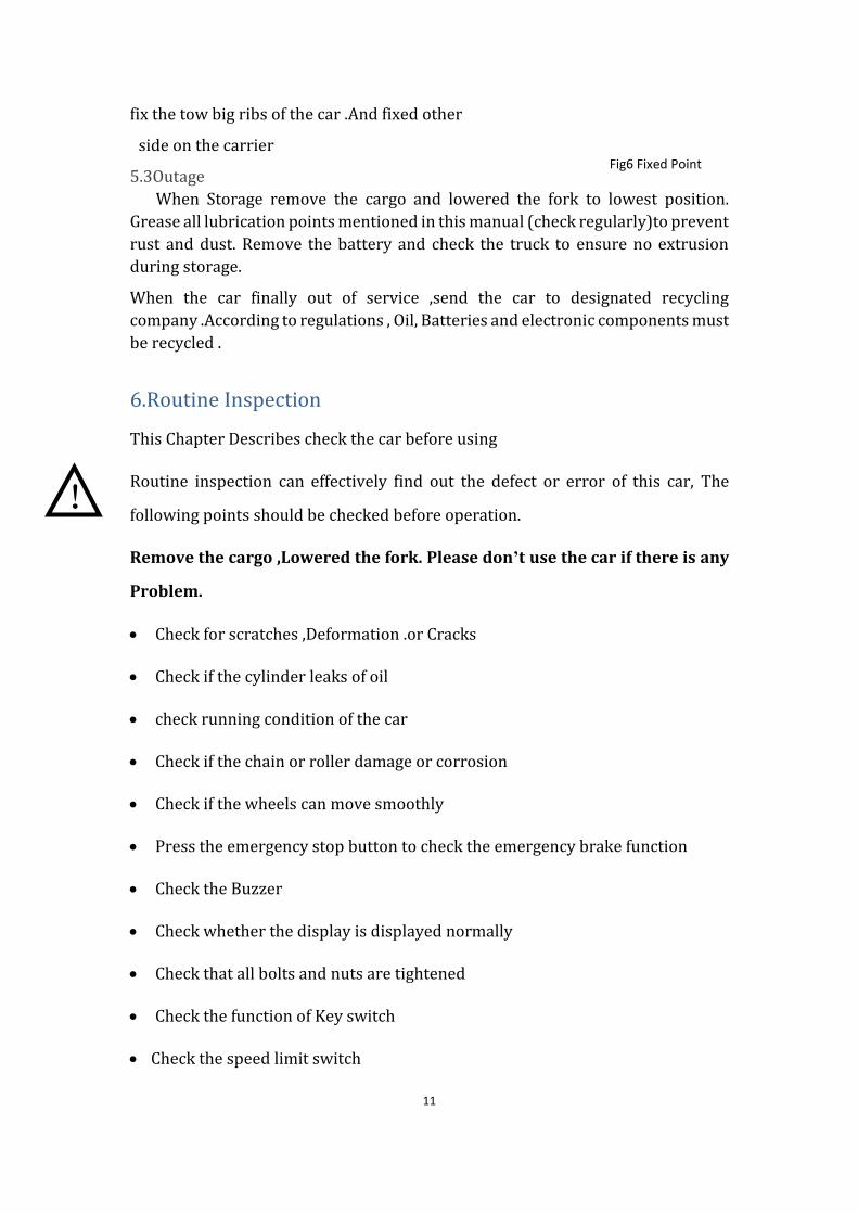
The Truck should be firmly fixed on the truck during transportation
Lowered fork and parking the truck safety
As figure 6 shows Use the special binding belt to
! Fig 5 Lifting Point
11
fix the tow big ribs of the car .And fixed other
side on the carrier
5.3Outage
When Storage remove the cargo and lowered the fork to lowest position.
Grease all lubrication points mentioned in this manual (check regularly)to prevent
rust and dust. Remove the battery and check the truck to ensure no extrusion
during storage.
When the car finally out of service ,send the car to designated recycling
company .According to regulations , Oil, Batteries and electronic components must
be recycled .
6.Routine Inspection
This Chapter Describes check the car before using
Routine inspection can effectively find out the defect or error of this car, The
following points should be checked before operation.
Remove the cargo ,Lowered the fork. Please don’t use the car if there is any
Problem.
• Check for scratches ,Deformation .or Cracks
• Check if the cylinder leaks of oil
• check running condition of the car
• Check if the chain or roller damage or corrosion
• Check if the wheels can move smoothly
• Press the emergency stop button to check the emergency brake function
• Check the Buzzer
• Check whether the display is displayed normally
• Check that all bolts and nuts are tightened
• Check the function of Key switch
• Check the speed limit switch
Fig6 Fixed Point
!
12
• Visually Check for any damaged tube or wires
• If the car with Protective barrier .Check for damage and correct installation.
7.The Schematic diagram of Operating Mechanism
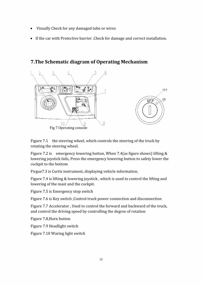
Fig 7 Operating console Fig 8 Key Switch
Figure 7.1 the steering wheel, which controls the steering of the truck by
rotating the steering wheel.
Figure 7.2 is emergency lowering button, When 7.4(as figure shows) lifting &
lowering joystick fails, Press the emergency lowering button to safety lower the
cockpit to the bottom
Firgue7.3 is Curtis instrument, displaying vehicle information.
Figure 7.4 is lifting & lowering joystick , which is used to control the lifting and
lowering of the mast and the cockpit.
Figure 7.5 is Emergency stop switch
Figure 7.6 is Key switch ,Control truck power connection and disconnection
Figure 7.7 Accelerator , Used to control the forward and backward of the truck,
and control the driving speed by controlling the degree of rotation
Figure 7.8,Horn button
Figure 7.9 Headlight switch
Figure 7.10 Waring light switch
13
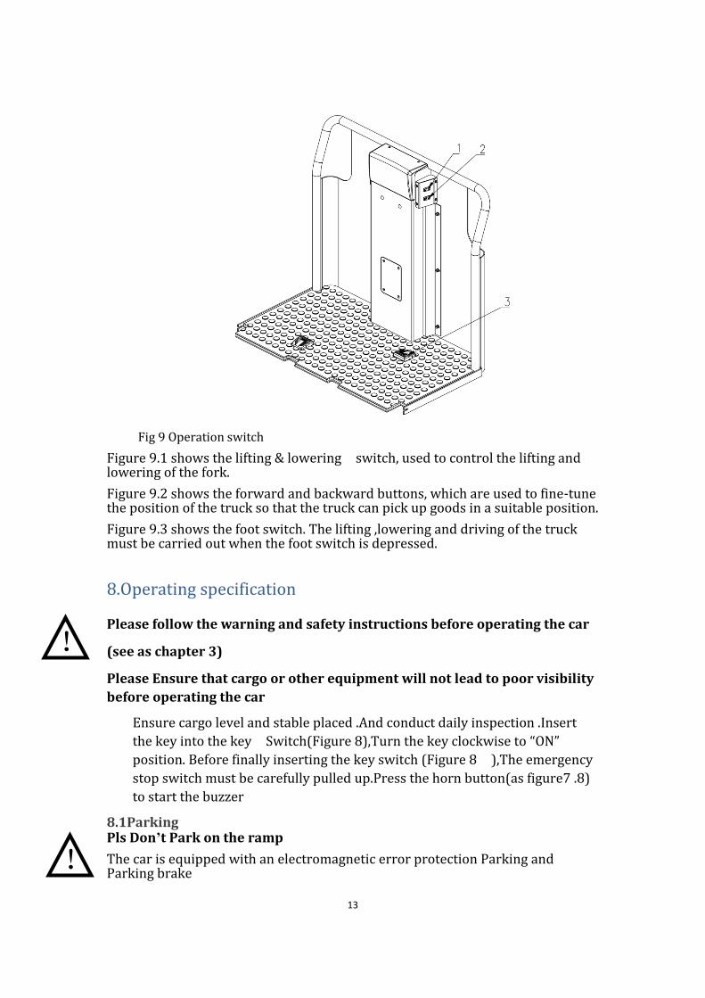
Fig 9 Operation switch
Figure 9.1 shows the lifting & lowering switch, used to control the lifting and lowering of the fork.
Figure 9.2 shows the forward and backward buttons, which are used to fine-tune the position of the truck so that the truck can pick up goods in a suitable position.
Figure 9.3 shows the foot switch. The lifting ,lowering and driving of the truck must be carried out when the foot switch is depressed.
8.Operating specification
Please follow the warning and safety instructions before operating the car
(see as chapter 3)
Please Ensure that cargo or other equipment will not lead to poor visibility
before operating the car
Ensure cargo level and stable placed .And conduct daily inspection .Insert
the key into the key Switch(Figure 8),Turn the key clockwise to “ON”
position. Before finally inserting the key switch (Figure 8 ),The emergency
stop switch must be carefully pulled up.Press the horn button(as figure7 .8)
to start the buzzer
8.1Parking Pls Don’t Park on the ramp
The car is equipped with an electromagnetic error protection Parking and Parking brake
!
!
14
During driving, you can brake by releasing the accelerator or the foot switch.
Please always lower the forks completely and drive the car to a safe area.Turn the key counterclockwise to the OFF position and pull out the key
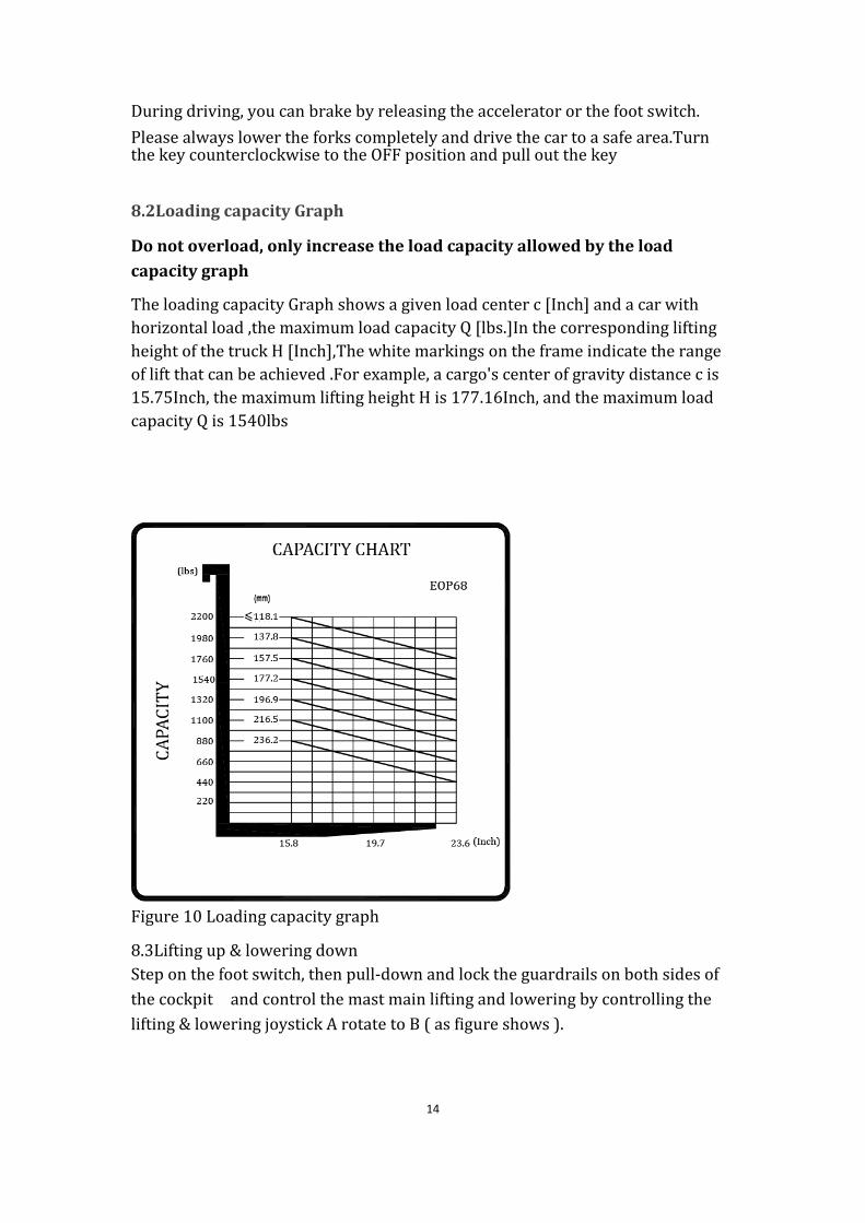
8.2Loading capacity Graph
Do not overload, only increase the load capacity allowed by the load
capacity graph
The loading capacity Graph shows a given load center c [Inch] and a car with
horizontal load ,the maximum load capacity Q [lbs.]In the corresponding lifting
height of the truck H [Inch],The white markings on the frame indicate the range
of lift that can be achieved .For example, a cargo's center of gravity distance c is
15.75Inch, the maximum lifting height H is 177.16Inch, and the maximum load
capacity Q is 1540lbs
Figure 10 Loading capacity graph
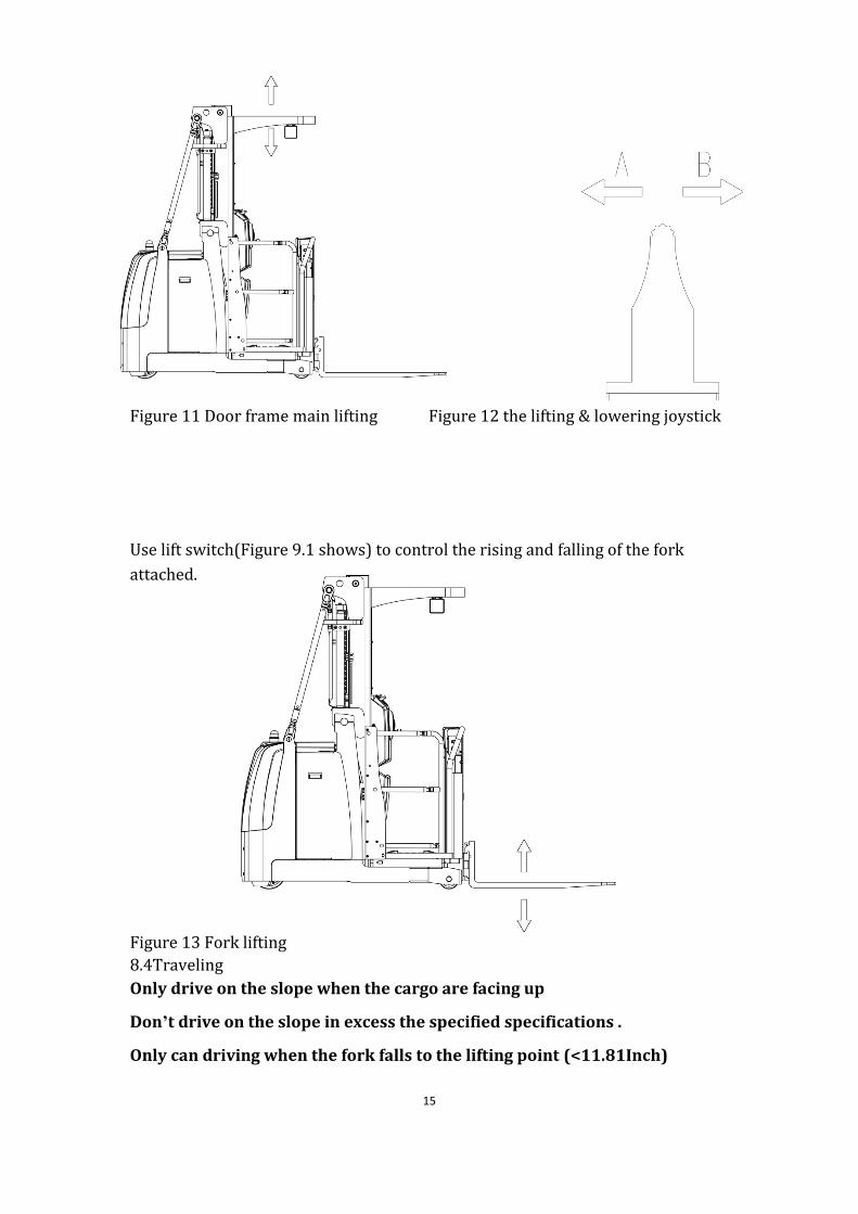
8.3Lifting up & lowering down
Step on the foot switch, then pull-down and lock the guardrails on both sides of
the cockpit and control the mast main lifting and lowering by controlling the
lifting & lowering joystick A rotate to B ( as figure shows ).
15
Figure 11 Door frame main lifting Figure 12 the lifting & lowering joystick
Use lift switch(Figure 9.1 shows) to control the rising and falling of the fork
attached.
Figure 13 Fork lifting
8.4Traveling
Only drive on the slope when the cargo are facing up
Don’t drive on the slope in excess the specified specifications .
Only can driving when the fork falls to the lifting point (<11.81Inch)
16
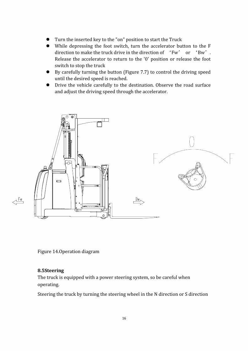
⚫ Turn the inserted key to the "on" position to start the Truck
⚫ While depressing the foot switch, turn the accelerator button to the F
direction to make the truck drive in the direction of ‘Fw’ or ‘Bw’.
Release the accelerator to return to the '0' position or release the foot
switch to stop the truck
⚫ By carefully turning the button (Figure 7.7) to control the driving speed
until the desired speed is reached.
⚫ Drive the vehicle carefully to the destination. Observe the road surface
and adjust the driving speed through the accelerator.
Figure 14.Operation diagram
8.5Steering
The truck is equipped with a power steering system, so be careful when
operating.
Steering the truck by turning the steering wheel in the N direction or S direction
17
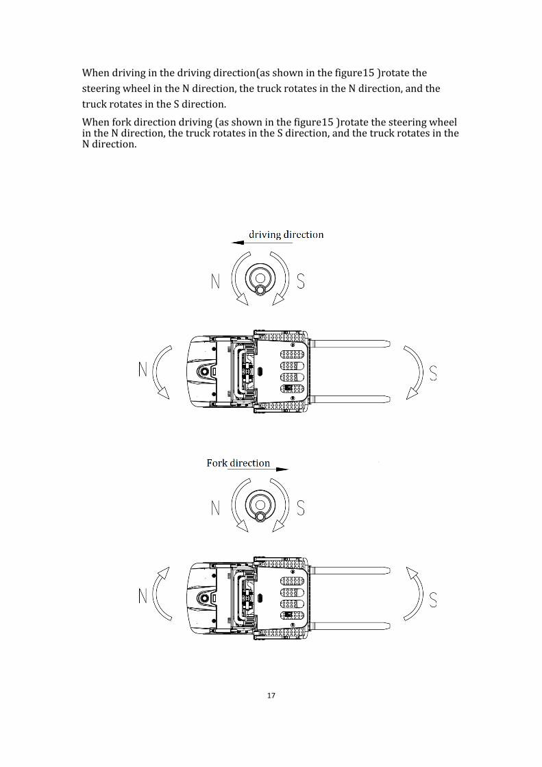
When driving in the driving direction(as shown in the figure15 )rotate the
steering wheel in the N direction, the truck rotates in the N direction, and the
truck rotates in the S direction.
When fork direction driving (as shown in the figure15 )rotate the steering wheel in the N direction, the truck rotates in the S direction, and the truck rotates in the N direction.
18
Fig:15 Steering diagram
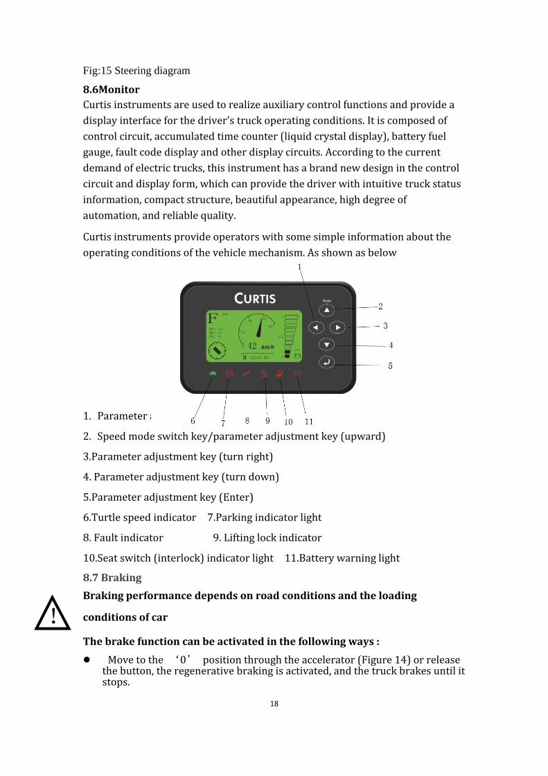
8.6Monitor
Curtis instruments are used to realize auxiliary control functions and provide a
display interface for the driver's truck operating conditions. It is composed of
control circuit, accumulated time counter (liquid crystal display), battery fuel
gauge, fault code display and other display circuits. According to the current
demand of electric trucks, this instrument has a brand new design in the control
circuit and display form, which can provide the driver with intuitive truck status
information, compact structure, beautiful appearance, high degree of
automation, and reliable quality.
Curtis instruments provide operators with some simple information about the
operating conditions of the vehicle mechanism. As shown as below
1. Parameter adjustment key (turn left)
2. Speed mode switch key/parameter adjustment key (upward)
3.Parameter adjustment key (turn right)
4. Parameter adjustment key (turn down)
5.Parameter adjustment key (Enter)
6.Turtle speed indicator 7.Parking indicator light
8. Fault indicator 9. Lifting lock indicator
10.Seat switch (interlock) indicator light 11.Battery warning light
8.7 Braking
Braking performance depends on road conditions and the loading
conditions of car
The brake function can be activated in the following ways :
⚫ Move to the ‘0’ position through the accelerator (Figure 14) or release the button, the regenerative braking is activated, and the truck brakes until it stops.
!
19
⚫ By directly moving the accelerator button (Figure 7.7) from one driving direction to the opposite direction, the truck will regeneratively brake until it starts to drive into the opposite direction.
⚫ Release the foot switch while driving to achieve truck braking.
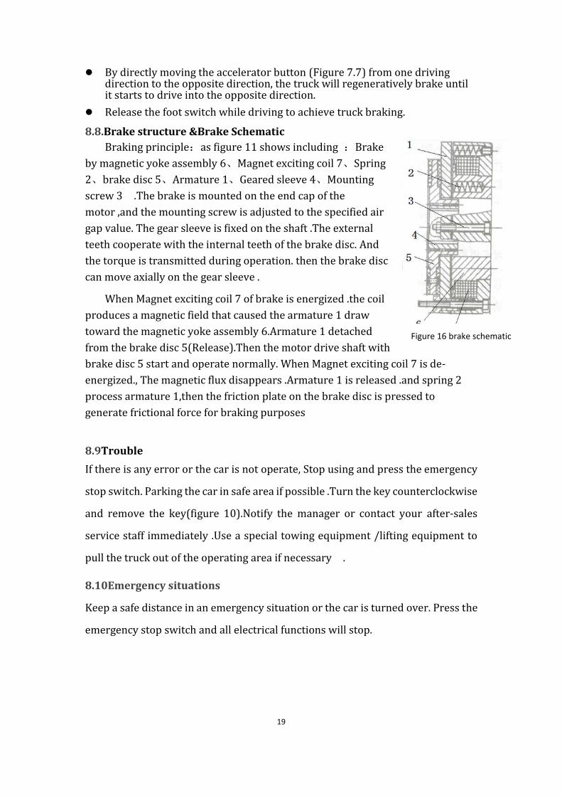
8.8.Brake structure &Brake Schematic
Braking principle:as figure 11 shows including :Brake
by magnetic yoke assembly 6、Magnet exciting coil 7、Spring
2、brake disc 5、Armature 1、Geared sleeve 4、Mounting
screw 3 .The brake is mounted on the end cap of the
motor ,and the mounting screw is adjusted to the specified air
gap value. The gear sleeve is fixed on the shaft .The external
teeth cooperate with the internal teeth of the brake disc. And
the torque is transmitted during operation. then the brake disc
can move axially on the gear sleeve .
When Magnet exciting coil 7 of brake is energized .the coil
produces a magnetic field that caused the armature 1 draw
toward the magnetic yoke assembly 6.Armature 1 detached
from the brake disc 5(Release).Then the motor drive shaft with
brake disc 5 start and operate normally. When Magnet exciting coil 7 is de-
energized., The magnetic flux disappears .Armature 1 is released .and spring 2
process armature 1,then the friction plate on the brake disc is pressed to
generate frictional force for braking purposes
8.9Trouble
If there is any error or the car is not operate, Stop using and press the emergency
stop switch. Parking the car in safe area if possible .Turn the key counterclockwise
and remove the key(figure 10).Notify the manager or contact your after-sales
service staff immediately .Use a special towing equipment /lifting equipment to
pull the truck out of the operating area if necessary .
8.10Emergency situations
Keep a safe distance in an emergency situation or the car is turned over. Press the
emergency stop switch and all electrical functions will stop.
Figure 16 brake schematic
20
9.Changing and Replacement for battery
⚫ Only Qualified personnel are allowed to repair or recharge the
battery .Please be sure to follow this manual and battery
manufacturer’s instructions.
⚫ The battery is Lead-Acid battery.
⚫ Battery recycling is subject to national regulations .Please follow
these rules .
⚫ When handling batteries .Don’t use open flame which my cause
gas explosion.
⚫ Don’t place flammable materials and work equipment that may
generate sparks within a distance of at least 6.56ft around the
forklift that needs to be recharged
⚫ It is forbidden to burn materials or burn liquid in the charging
area of the battery. It is strictly forbidden to smoke. The area must
be well ventilated.
⚫ Parking the car safely before you start charging ,installing
/replacing the battery
⚫ Before finishing the repairing .please make sure that all cables are
connected and there is no interference to the other part of car .
Only lead-acid batteries are allowed
The battery weight has a certain influence on car operation .Please
consider the max working temperature of the battery.
9.1Replacement
Park the car safely, Lower the fork to the lowest point .Turn off the car by
key(Figure8) and press the emergency stop switch, Take off the battery side
!
!

21
panel and the battery baffle, remove the battery connector, pull out the battery
from the side of the frame and hang it out. Caution: If the lifting equipment is
not safe. The battery may tip over .Installation is the opposite procedure of
remove , Please connect the positive terminal firstly .Otherwise the car is easy
to damage
Figure 17.Battery replacement
22
9.2Charging ⚫ Only be charged with included charger
⚫ Before using the charger ,Please fully understand the contents of the charger manual
⚫ Ensure good ventilation in charging room
Park the car in a safe area that provide dedicated power .Lower fork , and
remove the cargo. Turn off the power of car, Open the battery cover, then
connect the connector and Charger. The charger starts charging .Finishing
charging .Remove the connector from the charger, Connect the connector
to the car and cover the battery cover .
Battery specification :24V/280Ah ,Charger specification :24V/40A
10.Maintain Introduction ⚫ Only Qualified and trained personnel are allowed to maintain the
car .
⚫ Remove the cargo from the fork and lower the fork to the lowest point before maintenance .
⚫ Please use the designated binding equipment or lifting equipment in accordance with chapter 4 ,if it is necessary to lift the car .Before operation .Place safety device(such as lifting jacks,Wedges or Wooden blocks)under the car to prevent accidental falling ,moving or sliding .
⚫ Use approved and distributor ’S original accessories .
⚫ Please consider the machine failure and accident that may be caused by the leakage of hydraulic oil.
⚫ Only trained maintenance technicians are allowed to adjust the pressure Valve .
Check the key point on the maintenance list
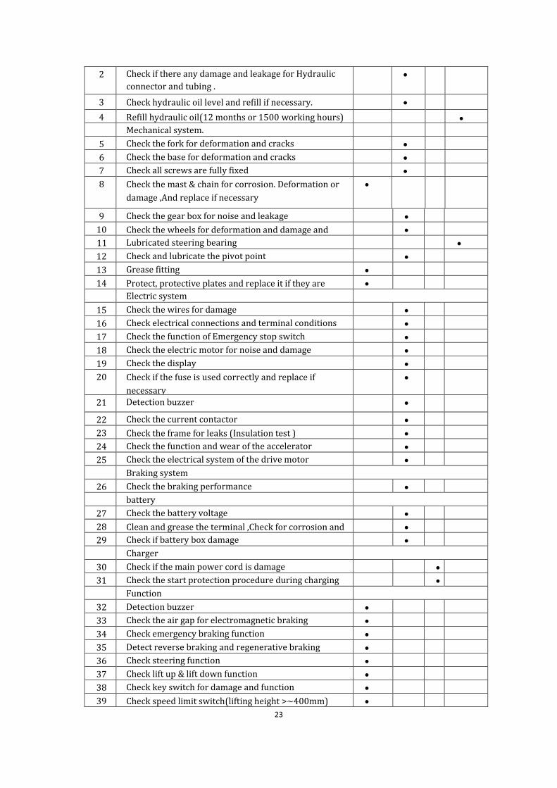
10.1Maintenance list
Table 6 Maintain list Time interval(Month)
1 3 6 12
No. Hydraulic system
1 Check if there is any damaged noise and leakage for
hydraulic cylinder and piston
•
!
!
23
2 Check if there any damage and leakage for Hydraulic
connector and tubing .
•
3 Check hydraulic oil level and refill if necessary. •
4 Refill hydraulic oil(12 months or 1500 working hours) •
Mechanical system.
5 Check the fork for deformation and cracks •
6 Check the base for deformation and cracks •
7 Check all screws are fully fixed •
8 Check the mast & chain for corrosion. Deformation or
damage ,And replace if necessary
•
9 Check the gear box for noise and leakage •
10 Check the wheels for deformation and damage and
replace if necessary
•
11 Lubricated steering bearing •
12 Check and lubricate the pivot point •
13 Grease fitting •
14 Protect, protective plates and replace it if they are
damaged
•
Electric system
15 Check the wires for damage •
16 Check electrical connections and terminal conditions •
17 Check the function of Emergency stop switch •
18 Check the electric motor for noise and damage •
19 Check the display •
20 Check if the fuse is used correctly and replace if
necessary
•
21 Detection buzzer •
22 Check the current contactor •
23 Check the frame for leaks (Insulation test ) •
24 Check the function and wear of the accelerator •
25 Check the electrical system of the drive motor •
Braking system
26 Check the braking performance •
battery
27 Check the battery voltage •
28 Clean and grease the terminal ,Check for corrosion and
damage
•
29 Check if battery box damage •
Charger
30 Check if the main power cord is damage •
31 Check the start protection procedure during charging •
Function
32 Detection buzzer •
33 Check the air gap for electromagnetic braking •
34 Check emergency braking function •
35 Detect reverse braking and regenerative braking •
36 Check steering function •
37 Check lift up & lift down function •
38 Check key switch for damage and function •
39 Check speed limit switch(lifting height >~400mm) •
24
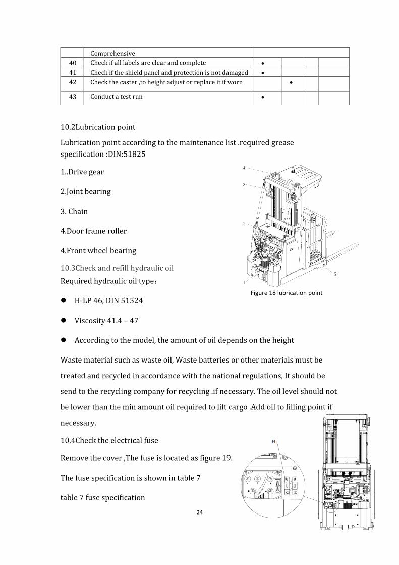
Figure 18 lubrication point
10.2Lubrication point
Lubrication point according to the maintenance list .required grease
specification :DIN:51825
1..Drive gear
2.Joint bearing
3. Chain
4.Door frame roller
4.Front wheel bearing
10.3Check and refill hydraulic oil
Required hydraulic oil type:
⚫ H-LP 46, DIN 51524
⚫ Viscosity 41.4 – 47
⚫ According to the model, the amount of oil depends on the height
Waste material such as waste oil, Waste batteries or other materials must be
treated and recycled in accordance with the national regulations, It should be
send to the recycling company for recycling .if necessary. The oil level should not
be lower than the min amount oil required to lift cargo .Add oil to filling point if
necessary.
10.4Check the electrical fuse
Remove the cover ,The fuse is located as figure 19.
The fuse specification is shown in table 7
table 7 fuse specification
Comprehensive
40 Check if all labels are clear and complete •
41 Check if the shield panel and protection is not damaged •
42 Check the caster ,to height adjust or replace it if worn •
43 Conduct a test run •

25
Figure 19 Fuse
Code Specificatio
n
Qty FU1 300A 2
10.5 Remove and reinstall the shield
Do not use the car if the shield is damaged or not installed properly.
If the shield needs to be removed, unscrew the fixed screw and carefully
remove the shield, the screw is still on the shield. When reinstalling, place the
shield in the correct position and secure each screw properly. If you need to
replace parts, please contact your nearest after-sales service partner.
26
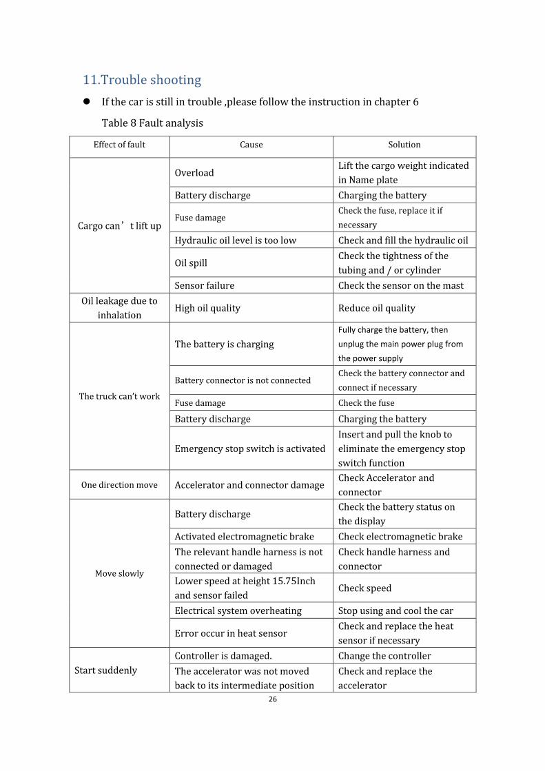
11.Trouble shooting
⚫ If the car is still in trouble ,please follow the instruction in chapter 6
Table 8 Fault analysis
Effect of fault Cause Solution
Cargo can’t lift up
Overload Lift the cargo weight indicated
in Name plate
Battery discharge Charging the battery
Fuse damage Check the fuse, replace it if
necessary
Hydraulic oil level is too low Check and fill the hydraulic oil
Oil spill Check the tightness of the
tubing and / or cylinder
Sensor failure Check the sensor on the mast
Oil leakage due to
inhalation High oil quality Reduce oil quality
The truck can’t work
The battery is charging
Fully charge the battery, then
unplug the main power plug from
the power supply
Battery connector is not connected Check the battery connector and
connect if necessary
Fuse damage Check the fuse
Battery discharge Charging the battery
Emergency stop switch is activated
Insert and pull the knob to
eliminate the emergency stop
switch function
One direction move Accelerator and connector damage Check Accelerator and
connector
Move slowly
Battery discharge Check the battery status on
the display
Activated electromagnetic brake Check electromagnetic brake
The relevant handle harness is not
connected or damaged
Check handle harness and
connector
Lower speed at height 15.75Inch
and sensor failed Check speed
Electrical system overheating Stop using and cool the car
Error occur in heat sensor Check and replace the heat
sensor if necessary
Start suddenly
Controller is damaged. Change the controller
The accelerator was not moved
back to its intermediate position
Check and replace the
accelerator
27
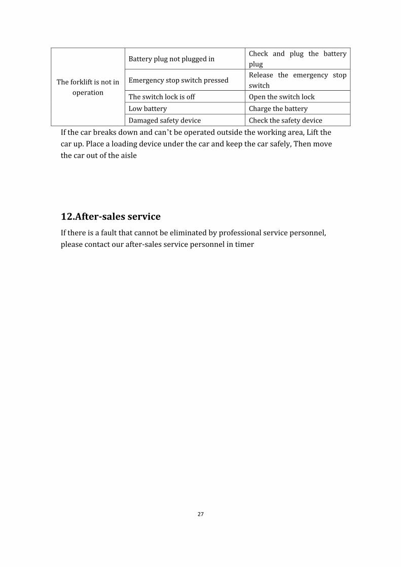
The forklift is not in
operation
Battery plug not plugged in Check and plug the battery
plug
Emergency stop switch pressed Release the emergency stop
switch
The switch lock is off Open the switch lock
Low battery Charge the battery
Damaged safety device Check the safety device
If the car breaks down and can’t be operated outside the working area, Lift the
car up. Place a loading device under the car and keep the car safely, Then move
the car out of the aisle
12.After-sales service
If there is a fault that cannot be eliminated by professional service personnel,
please contact our after-sales service personnel in timer
28
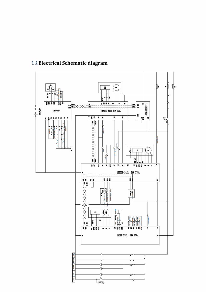
13.Electrical Schematic diagram
29
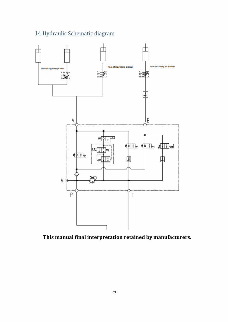
14.Hydraulic Schematic diagram
This manual final interpretation retained by manufacturers.