Embed Size (px)
Citation preview
The INL is a U.S. Department of Energy National Laboratory operated by Battelle Energy Alliance
INL/EXT-07-13073
Occupational Radiation Exposure Analysis of US ITER DCLL TBM
Brad J. Merrill Lee C. Cadwallader Mohamad Dagher
August 2007
INL/EXT-07-13073
Occupational Radiation Exposure Analysis of US ITER DCLL TBM
Brad J. Merrill1Lee C. Cadwallader1
Mohamad Dagher2
1Idaho National Laboratory 2University of California Los Angeles
August 2007
Idaho National Laboratory Idaho Falls, Idaho 83415
Prepared for the U.S. Department of Energy Office of Nuclear Energy
Under DOE Idaho Operations Office Contract DE-AC07-05ID14517
iii
ABSTRACT
This report documents an Occupational Radiation Exposure (ORE) analysis that was performed for the US International Thermonuclear Experimental Reactor (ITER) Dual Coolant Lead Lithium (DCLL) Test Blanket Module (TBM). This analysis was performed with the QADMOD dose code for anticipated maintenance activities for this TBM concept and its ancillary systems. The QADMOD code was used to model the PbLi cooling loop of this TBM concept by specifying gamma ray source terms that simulated radioactive material within the piping, valves, heat exchanger, permeator, pump, drain tank, and cold trap of this cooling system. Estimates of the maintenance tasks that will have to be performed and the time required to perform these tasks where developed based on either expert opinion or on industrial maintenance experience for similar technologies. This report details the modeling activity and the calculated doses for the maintenance activities envisioned for the US DCLL TBM.
iv
ACRONYMS
AEU Ancillary Equipment Unit
DCLL Dual Coolant Lead Lithium
DEMO Fusion Demonstration Reactor
EU European Union
FFTF Fast Flux Test Facility
FPY Full Power Year
FS Ferritic Steel
INL Idaho National Laboratory
ITER International Thermonuclear Experimental Reactor
IO International Organization
mSv milli Sieverts
MTTR Mean Time to Repair
ORE Occupational Radiation Exposure
ORNL Oak Ridge National Laboratory
p-mSv Person milli Sieverts
PbLi Lead Lithium
PWR Pressurized Water Reactor
RSICC Radiation Safety Information Computational Center
TBM Test Blanket Module
TBWG Test Blanket Working Group
TCWS Tokamak Cooling Water System
TRITEX Tritium Experiment in PbLi

v

vii
CONTENTS
ABSTRACT................................................................................................................................................. iv
ACRONYMS............................................................................................................................................... iv
1. INTRODUCTION.............................................................................................................................. 1
2. DCLL TBM SYSTEM DESCRIPTION ............................................................................................ 2
3. ANTICIPATED MAINTENANCE ACTIVITIES TIME ESTIMATES........................................... 3
3.1 TBM Replacement Time Estimate ............................................................................................... 4
3.2 PbLi AEU Maintenance Time Estimate ....................................................................................... 5
4. APPROACH TAKEN AND SOURCE TERMS ............................................................................. 11
5. OCCUPATIONAL RADIATION EXPOSURE ESTIMATE.......................................................... 20
6. CONCLUSIONS .............................................................................................................................. 20
7. REFERENCES................................................................................................................................. 24
Appendix A- Detail Time Estimate for Replacing the DCLL TBM........................................................... 26
FIGURES
1. Physical layout of DCLL TBM in the ITER equatorial port cell.............................................................. 2
2. View of Ancillary Equipment Unit as it resides in the transporter cask ................................................... 3
3. Depiction of the inert atmosphere seal bag for welding piping .............................................................. 10
4. Illustration of QADMOD-GP source terms locations used to model the DCLL AEU........................... 15
5. QADMOD-GP radiation field for the DCLL AEU................................................................................. 16
6. QADMOD-GP radiation field for the DCLL AEU at radial slices through the tritium permeator and the PbLi heat exchanger ......................................................................................................................... 17
7. AEU component locations at which maintenance dose rates where calculated with the QADMOD-GP code .................................................................................................................................................. 18
8. AEU valve locations at which maintenance dose rates where calculated with the QADMOD-GP
Code.................................................................................................................................................. 19
viii
TABLES
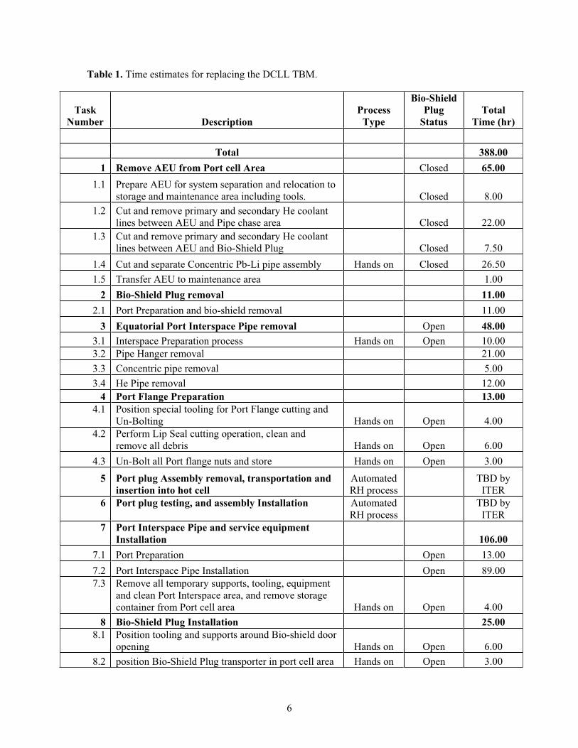
1. Time estimates for replacing the DCLL TBM.......................................................................................... 6
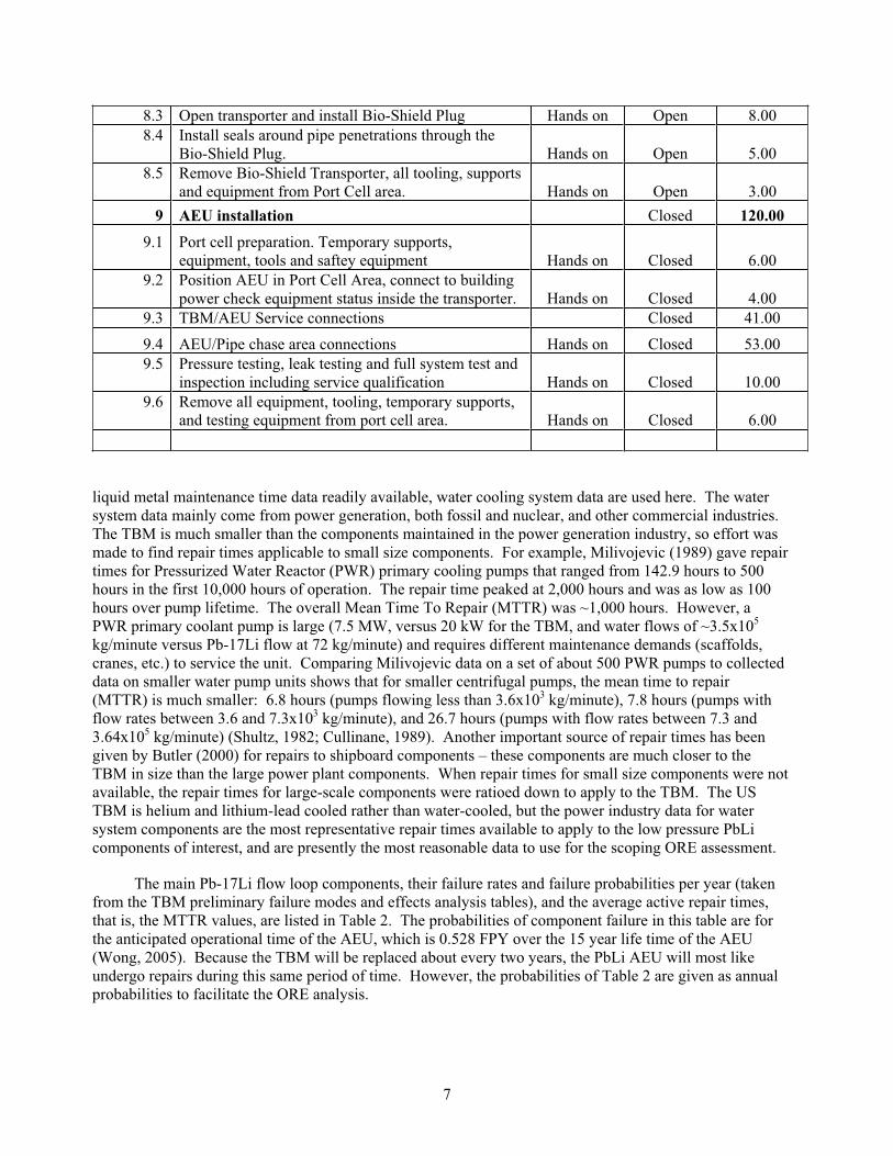
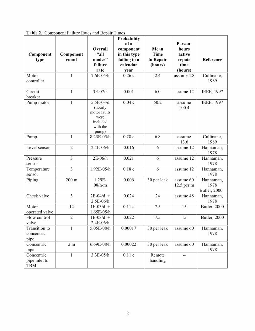
2. Component Failure Rates and Repair Times ............................................................................................ 8
3. Comparison of MicroShield to QADMOD-GP dose rates for a 1 m long AEU 9 cm pipe with a PbLi film adhering to the inside of the pipe.............................................................................................. 14
4. QADMOD-GP predicted dose rates as strategic maintenance locations of the AEU............................. 14
5. Predicted maintenance doses for replacing the DCLL TBM .................................................................. 22
6. Predicted doses for AEU component maintenance................................................................................. 23
1
Occupational Radiation Exposure Analysis of US ITER DCLL TBM
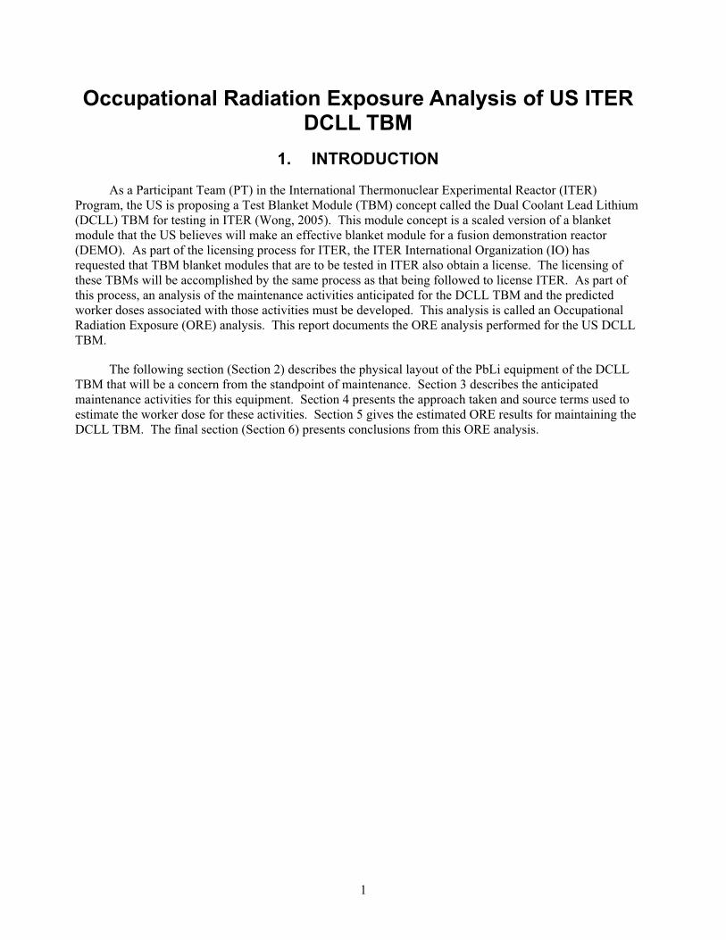
1. INTRODUCTION
As a Participant Team (PT) in the International Thermonuclear Experimental Reactor (ITER) Program, the US is proposing a Test Blanket Module (TBM) concept called the Dual Coolant Lead Lithium (DCLL) TBM for testing in ITER (Wong, 2005). This module concept is a scaled version of a blanket module that the US believes will make an effective blanket module for a fusion demonstration reactor (DEMO). As part of the licensing process for ITER, the ITER International Organization (IO) has requested that TBM blanket modules that are to be tested in ITER also obtain a license. The licensing of these TBMs will be accomplished by the same process as that being followed to license ITER. As part of this process, an analysis of the maintenance activities anticipated for the DCLL TBM and the predicted worker doses associated with those activities must be developed. This analysis is called an Occupational Radiation Exposure (ORE) analysis. This report documents the ORE analysis performed for the US DCLL TBM.
The following section (Section 2) describes the physical layout of the PbLi equipment of the DCLL TBM that will be a concern from the standpoint of maintenance. Section 3 describes the anticipated maintenance activities for this equipment. Section 4 presents the approach taken and source terms used to estimate the worker dose for these activities. Section 5 gives the estimated ORE results for maintaining the DCLL TBM. The final section (Section 6) presents conclusions from this ORE analysis.
2
2. DCLL TBM System Description
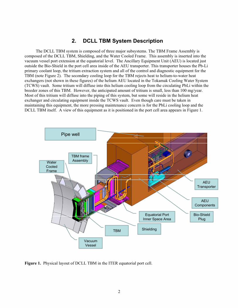
The DCLL TBM system is composed of three major subsystems. The TBM Frame Assembly is composed of the DCLL TBM, Shielding, and the Water Cooled Frame. This assembly is inserted into the vacuum vessel port extension at the equatorial level. The Ancillary Equipment Unit (AEU) is located just outside the Bio-Shield in the port cell area inside of the AEU transporter. This transporter houses the Pb-Li primary coolant loop, the tritium extraction system and all of the control and diagnostic equipment for the TBM (note Figure 2). The secondary cooling loop for the TBM rejects heat to helium-to-water heat exchangers (not shown in these figures) of the helium AEU located in the Tokamak Cooling Water System (TCWS) vault. Some tritium will diffuse into this helium cooling loop from the circulating PbLi within the breeder zones of this TBM. However, the anticipated amount of tritium is small, less than 100 mg/year. Most of this tritium will diffuse into the piping of this system, but some will reside in the helium heat exchanger and circulating equipment inside the TCWS vault. Even though care must be taken in maintaining this equipment, the more pressing maintenance concern is for the PbLi cooling loop and the DCLL TBM itself. A view of this equipment as it is positioned in the port cell area appears in Figure 1.
AEUTransporter
AEUComponents
Bio-Shield Plug
Equatorial Port Inner Space Area
Vacuum Vessel
TBM
TBM frame Assembly
Shielding
Pipe well
Water Cooled Frame
Figure 1. Physical layout of DCLL TBM in the ITER equatorial port cell.
3
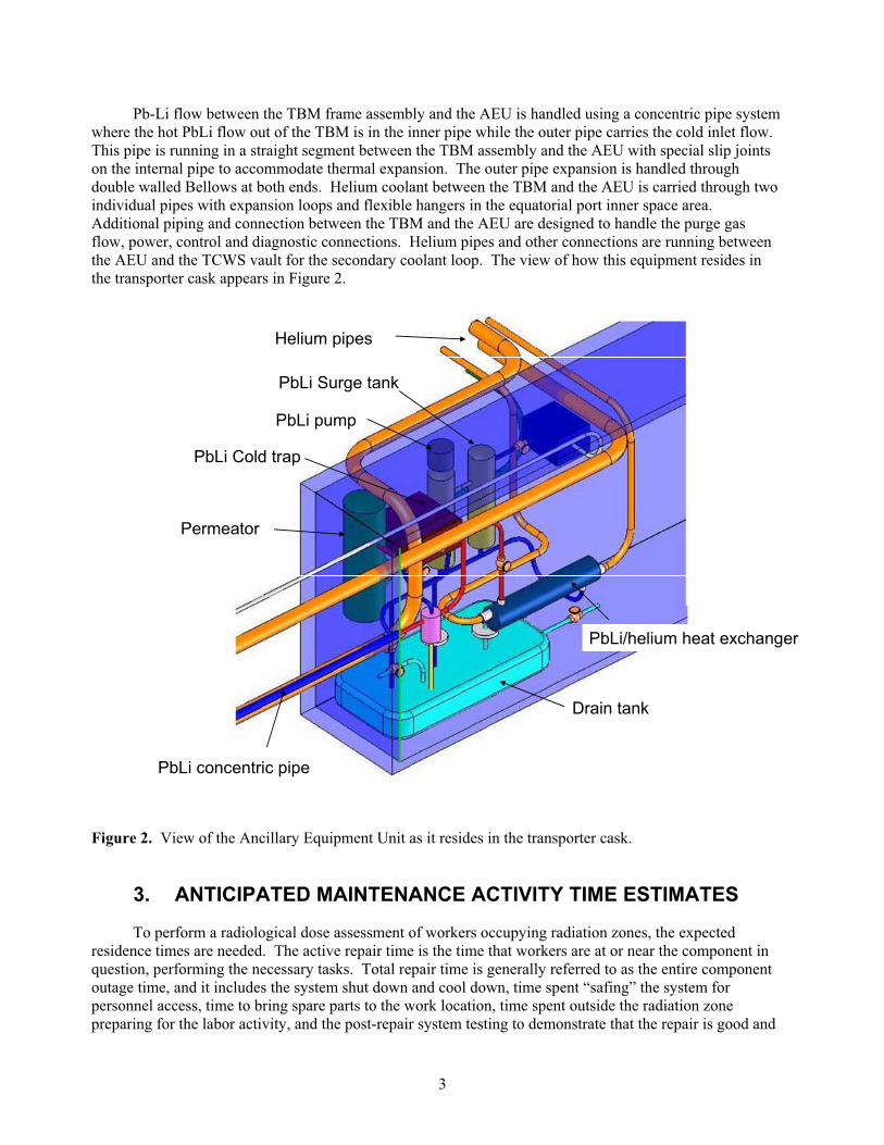
Pb-Li flow between the TBM frame assembly and the AEU is handled using a concentric pipe system where the hot PbLi flow out of the TBM is in the inner pipe while the outer pipe carries the cold inlet flow. This pipe is running in a straight segment between the TBM assembly and the AEU with special slip joints on the internal pipe to accommodate thermal expansion. The outer pipe expansion is handled through double walled Bellows at both ends. Helium coolant between the TBM and the AEU is carried through two individual pipes with expansion loops and flexible hangers in the equatorial port inner space area. Additional piping and connection between the TBM and the AEU are designed to handle the purge gas flow, power, control and diagnostic connections. Helium pipes and other connections are running between the AEU and the TCWS vault for the secondary coolant loop. The view of how this equipment resides in the transporter cask appears in Figure 2.
PbLi concentric pipe
Drain tank
PbLi/helium heat exchanger
PbLi pump
Permeator
PbLi Surge tank
PbLi Cold trap
Helium pipes
Figure 2. View of the Ancillary Equipment Unit as it resides in the transporter cask.
3. ANTICIPATED MAINTENANCE ACTIVITY TIME ESTIMATES
To perform a radiological dose assessment of workers occupying radiation zones, the expected residence times are needed. The active repair time is the time that workers are at or near the component in question, performing the necessary tasks. Total repair time is generally referred to as the entire component outage time, and it includes the system shut down and cool down, time spent “safing” the system for personnel access, time to bring spare parts to the work location, time spent outside the radiation zone preparing for the labor activity, and the post-repair system testing to demonstrate that the repair is good and
4
the system can be returned to service. The active repair time is the time sought here to give radiation dose estimates. This section describes the anticipated maintenance activities for the TBM and its PbLi AEU. The helium AEU will contain insignificant levels of tritium (< 0.1 g) and worker doses from maintenance activities on the equipment of this system, located in the TCWS vault where radiation levels are also low, will be negligible in comparison to the maintenance activities for the PbLi AEU, which are described in this section.
3.1 TBM Replacement Time Estimate
The major maintenance activity for the DCLL TBM will be the replacement of the TBM, which will occur approximately every other year during ITER DT operation. The maintenance operations for replacing a TBM assembly are:
1. Removal of the AEU from the equatorial port cell area
2. Clearing the port inner space area and removing the TBM Frame assembly from the vacuum vessel
3. Transporting TBM Frame assembly to the hot cell for further work
4. TBM Frame assembly re-installation into the equatorial port cell area, and
5. Reconnecting of all piping and provisioning the AEU to support the TBM operation.
Operations at the equatorial port area are assumed to be primarily hands-on operations as long as the vacuum vessel plug is closed. The TBM frame assembly removal and insertion in the vacuum vessel port extension is a completely automated process designed by ITER and using ITER’s standard port plug removal transporter.
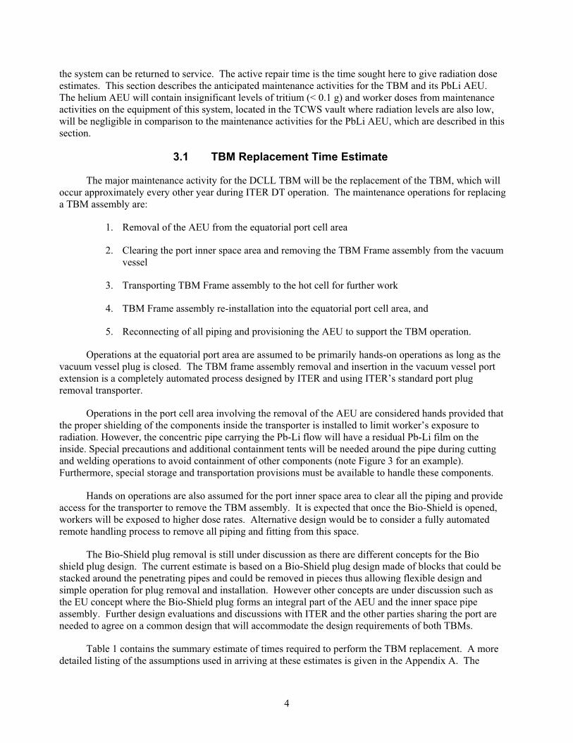
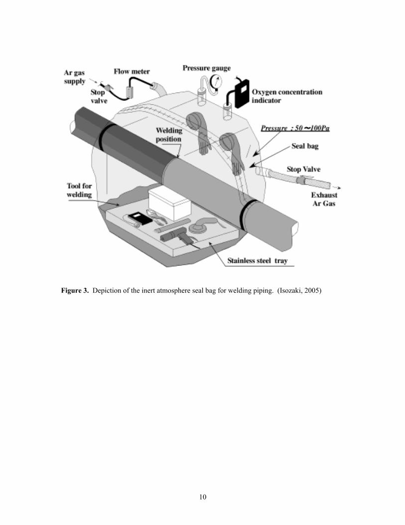
Operations in the port cell area involving the removal of the AEU are considered hands provided that the proper shielding of the components inside the transporter is installed to limit worker’s exposure to radiation. However, the concentric pipe carrying the Pb-Li flow will have a residual Pb-Li film on the inside. Special precautions and additional containment tents will be needed around the pipe during cutting and welding operations to avoid containment of other components (note Figure 3 for an example). Furthermore, special storage and transportation provisions must be available to handle these components.
Hands on operations are also assumed for the port inner space area to clear all the piping and provide access for the transporter to remove the TBM assembly. It is expected that once the Bio-Shield is opened, workers will be exposed to higher dose rates. Alternative design would be to consider a fully automated remote handling process to remove all piping and fitting from this space.
The Bio-Shield plug removal is still under discussion as there are different concepts for the Bio shield plug design. The current estimate is based on a Bio-Shield plug design made of blocks that could be stacked around the penetrating pipes and could be removed in pieces thus allowing flexible design and simple operation for plug removal and installation. However other concepts are under discussion such as the EU concept where the Bio-Shield plug forms an integral part of the AEU and the inner space pipe assembly. Further design evaluations and discussions with ITER and the other parties sharing the port are needed to agree on a common design that will accommodate the design requirements of both TBMs.
Table 1 contains the summary estimate of times required to perform the TBM replacement. A more detailed listing of the assumptions used in arriving at these estimates is given in the Appendix A. The
5
current time estimate presented in this report is based on performing multiple concurrent operations at the same time. However it does not take into account operations needed by the other parties sharing the same port. This may create time and scheduling conflicts that will affect the procedure, the allowed time, and may impact some of the component and equipment design as well. As more design details become available and more interaction between the parties takes place, the TBM maintenance procedure will most likely develop further and more accurate estimates can be presented.
3.2 PbLi AEU Maintenance Time Estimate
In addition to the major activity of TBM replacement, components of the PbLi AEU will have to be maintained during the TBM replacement operation. The anticipated maintenance activities will depend on the failure rate of the components of the PbLi AEU. Unfortunately, there is very little data on PbLi systems from which to estimate how often a given component of this AEU will have to be maintained or replaced. As with the component failure rate data needs in the Failure Modes and Effects Analysis for the Pb-17Li flow loop (Cadwallader, 2007), representative data from liquid sodium fission reactors was sought first as representative data for this assessment. However, literature searches revealed that there has been little published information on maintenance of US sodium reactors. Two papers gave some overall radiation exposures for two sodium reactors, the Fast Flux Test Facility (FFTF) near Hanford, Washington (Bunch, 1990), and the Experimental Breeder Reactor-II near Idaho Falls, Idaho (Olson, 1986).
Other sodium–cooled and liquid metal reactor experiences were searched as well. Notably, the Dounreay Fast Reactor, a NaK cooled, 50 MW-thermal plant, discovered a small leak of ~100 liters NaK per day in May 1967 (Matthews, 1968). The plant shut down to find and repair the leak in a 4 inch pipeline on July 29, 1967. The Dounreay plant restarted on June 22, 1968. This was roughly eleven months of outage time for a 100 liter/day leak. The Phoenix sodium-cooled plant had cracks forming in some of the superheater and reheater tubes (Cavagna, 2006). In 2001 a building was constructed to handle the tubes for weld repair. Over nine months in 2002, forty-seven steam generator superheater/reheater modules (7 tubes per module) measuring 16.9 m long were removed, given > 160 hours of cleaning, and then were welded and radiographed. In two additional months in 2002, all of the modules were reassembled in the Phoenix steam generator. Assuming that just one of these modules is comparable to a TBM heat exchanger, then 11 months for 334 days/47 modules gives roughly 7 days per module. This is a poor average, since the time to uninstall and reinstall the tube module is distributed over all of the modules, but it does give the order of magnitude of a tube repair activity.
This document treats repair time, which is the time expected for the active repair of components by corrective maintenance (e.g., replacing a seal on an existing component). Times for operational tests, surveillance tests and other inspections are not known at present, although some operational testing (e.g. pressure testing) for the AEU has been included in the time estimate of Section 3.1. Some component repair times for water system components in nuclear and in typical industrial environments have been assembled to apply to the Pb-17Li flow loop. Unfortunately, statistical tabulations of repair time data are sparse in the literature. The best known sources of averaged labor times are for construction labor estimating (Means, 2007) and for automobile mechanical repair (Chilton, 2007). Without fusion or fission
6
Table 1. Time estimates for replacing the DCLL TBM.
TaskNumber Description
ProcessType
Bio-ShieldPlug
StatusTotal
Time (hr)
Total 388.00 1 Remove AEU from Port cell Area Closed 65.00
1.1 Prepare AEU for system separation and relocation to storage and maintenance area including tools. Closed 8.00
1.2 Cut and remove primary and secondary He coolant lines between AEU and Pipe chase area Closed 22.00
1.3 Cut and remove primary and secondary He coolant lines between AEU and Bio-Shield Plug Closed 7.50
1.4 Cut and separate Concentric Pb-Li pipe assembly Hands on Closed 26.50 1.5 Transfer AEU to maintenance area 1.00
2 Bio-Shield Plug removal 11.00 2.1 Port Preparation and bio-shield removal 11.00
3 Equatorial Port Interspace Pipe removal Open 48.00 3.1 Interspace Preparation process Hands on Open 10.00 3.2 Pipe Hanger removal 21.00 3.3 Concentric pipe removal 5.00 3.4 He Pipe removal 12.00
4 Port Flange Preparation 13.00 4.1 Position special tooling for Port Flange cutting and
Un-Bolting Hands on Open 4.00 4.2 Perform Lip Seal cutting operation, clean and
remove all debris Hands on Open 6.00 4.3 Un-Bolt all Port flange nuts and store Hands on Open 3.00
5 Port plug Assembly removal, transportation and insertion into hot cell
AutomatedRH process
TBD by ITER
6 Port plug testing, and assembly Installation AutomatedRH process
TBD by ITER
7 Port Interspace Pipe and service equipment Installation 106.00
7.1 Port Preparation Open 13.00 7.2 Port Interspace Pipe Installation Open 89.00 7.3 Remove all temporary supports, tooling, equipment
and clean Port Interspace area, and remove storage container from Port cell area Hands on Open 4.00
8 Bio-Shield Plug Installation 25.00 8.1 Position tooling and supports around Bio-shield door
opening Hands on Open 6.00 8.2 position Bio-Shield Plug transporter in port cell area Hands on Open 3.00
7
8.3 Open transporter and install Bio-Shield Plug Hands on Open 8.00 8.4 Install seals around pipe penetrations through the
Bio-Shield Plug. Hands on Open 5.00 8.5 Remove Bio-Shield Transporter, all tooling, supports
and equipment from Port Cell area. Hands on Open 3.00 9 AEU installation Closed 120.00
9.1 Port cell preparation. Temporary supports, equipment, tools and saftey equipment Hands on Closed 6.00
9.2 Position AEU in Port Cell Area, connect to building power check equipment status inside the transporter. Hands on Closed 4.00
9.3 TBM/AEU Service connections Closed 41.00 9.4 AEU/Pipe chase area connections Hands on Closed 53.00 9.5 Pressure testing, leak testing and full system test and
inspection including service qualification Hands on Closed 10.00 9.6 Remove all equipment, tooling, temporary supports,
and testing equipment from port cell area. Hands on Closed 6.00
liquid metal maintenance time data readily available, water cooling system data are used here. The water system data mainly come from power generation, both fossil and nuclear, and other commercial industries. The TBM is much smaller than the components maintained in the power generation industry, so effort was made to find repair times applicable to small size components. For example, Milivojevic (1989) gave repair times for Pressurized Water Reactor (PWR) primary cooling pumps that ranged from 142.9 hours to 500 hours in the first 10,000 hours of operation. The repair time peaked at 2,000 hours and was as low as 100 hours over pump lifetime. The overall Mean Time To Repair (MTTR) was ~1,000 hours. However, a PWR primary coolant pump is large (7.5 MW, versus 20 kW for the TBM, and water flows of ~3.5x10⁵
kg/minute versus Pb-17Li flow at 72 kg/minute) and requires different maintenance demands (scaffolds, cranes, etc.) to service the unit. Comparing Milivojevic data on a set of about 500 PWR pumps to collected data on smaller water pump units shows that for smaller centrifugal pumps, the mean time to repair (MTTR) is much smaller: 6.8 hours (pumps flowing less than 3.6x10³ kg/minute), 7.8 hours (pumps with flow rates between 3.6 and 7.3x10³ kg/minute), and 26.7 hours (pumps with flow rates between 7.3 and 3.64x10⁵ kg/minute) (Shultz, 1982; Cullinane, 1989). Another important source of repair times has been given by Butler (2000) for repairs to shipboard components – these components are much closer to the TBM in size than the large power plant components. When repair times for small size components were not available, the repair times for large-scale components were ratioed down to apply to the TBM. The US TBM is helium and lithium-lead cooled rather than water-cooled, but the power industry data for water system components are the most representative repair times available to apply to the low pressure PbLi components of interest, and are presently the most reasonable data to use for the scoping ORE assessment.
The main Pb-17Li flow loop components, their failure rates and failure probabilities per year (taken from the TBM preliminary failure modes and effects analysis tables), and the average active repair times, that is, the MTTR values, are listed in Table 2. The probabilities of component failure in this table are for the anticipated operational time of the AEU, which is 0.528 FPY over the 15 year life time of the AEU (Wong, 2005). Because the TBM will be replaced about every two years, the PbLi AEU will most like undergo repairs during this same period of time. However, the probabilities of Table 2 are given as annual probabilities to facilitate the ORE analysis.
8
Table 2. Component Failure Rates and Repair Times
Componenttype
Componentcount
Overall“all
modes”failure
rate
Probabilityof a
componentin this type failing in a calendar
year
MeanTime
to Repair(hours)
Person-hoursactiverepairtime
(hours)
Reference
Motorcontroller
1 7.6E-05/h 0.26 c 2.4 assume 4.8 Cullinane, 1989
Circuitbreaker
1 3E-07/h 0.001 6.0 assume 12 IEEE, 1997
Pump motor 1 5.5E-03/d (hourly
motor faults were
included with the pump)
0.04 c 50.2 assume 100.4
IEEE, 1997
Pump 1 8.23E-05/h 0.28 c 6.8 assume 13.6
Cullinane,1989
Level sensor 2 2.4E-06/h 0.016 6 assume 12 Hannaman, 1978
Pressuresensor
3 2E-06/h 0.021 6 assume 12 Hannaman, 1978
Temperature sensor
3 1.92E-05/h 0.18 c 6 assume 12 Hannaman, 1978
Piping 200 m 1.29E-08/h-m
0.006 30 per leak assume 60 12.5 per m
Hannaman, 1978
Butler, 2000 Check valve 3 2E-04/d +
2.5E-06/h 0.024 24 assume 48 Hannaman,
1978Motoroperated valve
12 1E-03/d + 1.65E-05/h
0.11 c 7.5 15 Butler, 2000
Flow control valve
2 1E-03/d + 2.4E-06/h
0.022 7.5 15 Butler, 2000
Transition to concentricpipe
1 5.05E-08/h 0.00017 30 per leak assume 60 Hannaman, 1978
Concentricpipe
2 m 6.69E-08/h 0.00022 30 per leak assume 60 Hannaman, 1978
Concentricpipe inlet to TBM
1 3.3E-05/h 0.11 c Remote handling
--
9
Table 2. Component Failure Rates and Repair Times, continued.
Componenttype
Componentcount
Overall“all
modes”failure
rate
Probabilityof a
componentin this type failing in a calendar
year
MeanTime
to Repair(hours)
Person-hoursactiverepairtime
(hours)
Reference
Concentricpipe outlet from TBM
1 1E-04/y 0.0001 Remote handling
--
Mixing tank 1 1.05E-07/h 0.00035 40 assume 80 Hannaman, 1978
T extraction tank
1 2.4E-06/h 0.008 30 assume 60 Hannaman, 1978
Pb-Li to He heatexchanger
1 4.11E-06/h 0.014 30 assume 60 Hannaman, 1978
Pump expansiontank
1 2.11E-05/h 0.07 c 40 assume 80 Hannaman, 1978
Cold trap 1 1.15E-05/h 0.039 c 20 assume 40 analyst judgment
Cold trap heat exchanger
1 1.1E-06/h 0.004 20 assume 40 analyst judgment
Drain tank 1 1.1E-06/h 0.004 40 assume 80 Hannaman, 1978
Rupture disk 1 1E-04/d + 1E-05/h
0.034 c 1 assume 2 analyst judgment
Pressure relief valve
1 4.16E-06/h 0.014 7.5 15 assumed from Butler,
2000Drain tank electric heater
1 1.56E-06/h 0.005 4 assume 8 analyst judgment
Notes: Used 3,360 Pb-17Li loop operating hours/year to obtain annual failure probabilities. Used guidance from Derdiger (1981) to estimate man-hours needed given the MTTR value. Probability of complete overhaul or replacement over the 15-year lifetime of the TBM project (~50,000 hours operating time) is considered to occur if the (probability/year)(15 years) is greater than 0.5. If a “c”appears in the probability column then the component is expected to require a changeout; that is, one major overhaul or replacement during the 15-year project life. The motor controller is probably not in the radiation area, it can be close to the motor control center electrical panel.
10
Figure 3. Depiction of the inert atmosphere seal bag for welding piping. (Isozaki, 2005)
11
4. APPROACH TAKEN AND SOURCE TERMS
Two shielding codes available at INL were used to perform this ORE analysis, which are the MicroShield and QADMOD-GP codes. The MicroShield code (MicroShield, 2006) is a commercially available code from Grove Software. It is a deterministic code, that is, MicroShield is a ray tracing code. MicroShield uses simple gamma source geometries, which are spherical, cylindrical, annular, or planar sources. The code allows only one radioactive source per calculation, but this single source can include multiple radionuclides that emit gamma rays. A complete radionuclide data base is included with this code to facilitate the user in defining decay rates, gamma ray energies and dose conversion factors. MicroShield will allow the user the possibility to define multiple shields with buildup factors of the same geometries as the source, and as with the source terms, the code includes a data base for shield material densities, attenuation coefficients and buildup factors.
The QADMOD-GP code (Warkentin, 1990) was obtained from the Radiation Safety Information Computational Center (RSICC) at the Oak Ridge National Laboratory (ORNL). This code is a point kernel gamma-ray shielding code, which also performs a gamma ray tracing analysis for point-kernel source terms. QADMOD-GP will allow for either one distributed source, simulated by up to 27,000 point-kernel sources, or up to 1000 user defined point-kernel source locations for a given calculation. Cartesian, cylindrical, or spherical geometries are allowed for defining shielding and regions being modeled, with geometric progression buildup factors, attenuation coefficients and material densities available for some shielding materials. Both of these shielding codes calculate the equivalent dose rate (mSv/hr) at a number of user specified locations.
The primary difficulty in using either of these codes to perform the ORE analyses for the DCLL TBM and its PbLi AEU is the very complicated component arrangement of these systems, as can be seen in Figures 1 and 2. Because the MicroShield code only allows for a single source per calculation, modeling the complex radiation field of an AEU piping systems is not directly possible, plus summing the contributions manually to obtain the total dose at all of the maintenance location envision from multiple MicroShield source term calculations without introducing errors would be extremely difficult. The QADMOD-GP code also only allows for a single distributed source term per calculation, leaving the task of summing the dose from all of the individual AEU components up to the user. But, QADMOD-GP does allow for multiple point-kernel source definitions per calculation, which allows for a dose estimate from all of the AEU components within a single calculation provided that the point-kernel source terms can be defined to accurately simulate the radiation emitted by these components.
There are two additional problems with using the QADMOD-GP code for this analysis. The first is the QADMOD-GP combinatorial geometry input for defining shielding regions makes the modeling of complex systems, like the AEU, difficult for the user to specify correctly. The second is that the QADMOD-GP code, by default, only contains information for eight gamma ray energy groups to simulate the gamma energy spectrum of the AEU. The code also only includes material buildup factors, attenuation coefficients, and dose conversion factors for these eight energy groups. However, based on the radionuclides supplied by the user, the MicroShield code will automatically simulate the gamma ray energy spectrum with 25 groups by default, plus the required material buildup factors, attenuation coefficients, and dose conversion factors. Given the radionuclides present in the AEU, the MicroShield code defined 17 energy groups in the 0.015 to 1.5 MeV energy range. In this same energy range, QADMOD-GP only models three energy groups by default. This would mean that in order to obtain an accurate dose estimate with QADMOD-GP, new material buildup factors, attenuation coefficients, and dose conversion factors would have to be derived an supplied to the code through user input. The solution to this modeling
12
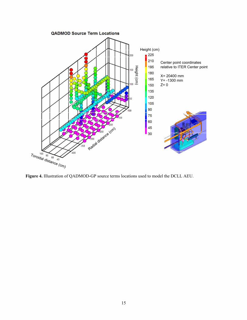
dilemma for the AEU was to realize that the dose rate predicted by any ray tracing code is directly proportional to strength of the user defined point-kernel or distribute gamma source. Therefore, a model that accurately represented the AEU could be developed by using multiple point-kernel source terms in QADMOD-GP (note Figure 4) and then adjust or “tune” the strength of these sources so that the predicted gamma dose from QADMOD-GP matched the result dose from MicroShield on a component by component basis. This would have the affect of simulating the gamma ray energy spectrum, attenuation, buildup, and anticipated dose by the QADMOD-GP multiple point-kernel source AEU model without having to define more energy groups or shielding in this QADMOD-GP model. The QADMOD-GP in essence is summing up the doses from all of the AEU components as predicted by the MicroShield code at a point in space. We present more details on this modeling approach below, but before we do, we will discuss the gamma source terms that the TBM and AEU will contain during maintenance.
There will be two sources of radioactive material in the AEU, activated PbLi and activated F82H corrosion products. During maintenance, most of the PbLi will reside in the drain tank. However, based on TRITEX facility (Feuerstein, 1999) experience it was discovered that after draining the TRITEX loop, PbLi films were found on the pipe walls that were on average ~45 mg/cm2. Similar films are expected to adhere to the inner surfaces of all of the components in the AEU. According to activation calculations performed for the DCLL TBM (Wong, 2005), these films will be radioactive, with the activity after one week dominated by Pb-203 (a gamma emitter).
In addition to the activated PbLi films, the hot surfaces within the TBM and the outlet PbLi pipe wall will undergo corrosion at the PbLi/Ferritic Steel (FS) interface. Because the TBM FS surfaces are activated, the corrosion products from TBM will mix into the PbLi bulk flow and be deposited, along with the non-radioactive FS corrosion products from the PbLi outlet pipe, on to the inside surfaces of the cooler components of the AEU, such as pipe walls, heat exchanger tubes, valves, permeator tubes, etc. The anticipated corrosion rate of these hot surfaces is 20 μm/yr at 450ºC based on experimental data (Moriyama, 1995). This corrosion will only occur at high PbLi temperatures and flow rates (e.g. during a pulse), therefore over the lifetime of the AEU there will be 41,500 x 400s or 0.526 full power years (FPY) of operation, which translates into ~11 μm of erosion from these hot surfaces. Because the cool area to hot area ratio in the TBM/AEU system is 6 to 1, then the predicted corrosion product thickness in the AEU will be about 1.8 μm. According to activation calculations performed for the TBM (Wong, 2005), Fe-55 and Mn-54 will dominate the corrosion film activity (gamma emitters) one week after reactor shutdown.
There is an added complication with respect to the corrosion products, and that is that unlike the PbLi which is continuously circulating through the neutron radiation field within the reactor, the corrosion products will be deposited outside of this field once they enter the PbLi flow. Once deposited on the walls of the AEU components, these corrosion products will begin to decay. To account for this decay, the following rate equation was solved for the film:
iiii CS
dtdC (1)
where Ci = concentration of the ith corrosion product radioactive element (m-3) t = deposition time (yr) Si = source of the ith corrosion product radioactive element (m-3yr-1), and
i = decay constant of the ith radioactive specie in the film (yr-1).
The source term of Equation 1 is the rate of concentration change by deposition of the ith
radioactive element from the TBM FS divided by the time over which the film forms within AEU (e.g., the lifetime of the AEU) times the fraction of corrosion coming from the TBM walls to the total corrosion from
13
all hot walls. For simplicity and conservatism, the radioactive element concentrations associated with the TBM wall corrosion products are those element concentrations that exist after end-of-life activation of the TBM (e.g., after 0.526 FPY). The solution to Equation 1 is straight forward with the result being as follows:
i
oi
i ie1CC (2)
where (yr) is the AEU lifetime in calendar years. Equation 2 was applied to the predominate radioactive elements (arbitrarily defined as those elements that have an activity > 1 Ci/m3, which is a factor of 105 less than the activity of Fe-55) of the activation calculation output files for the TBM (Wong, 2005) and the result used as the corrosion film radioactive elements.
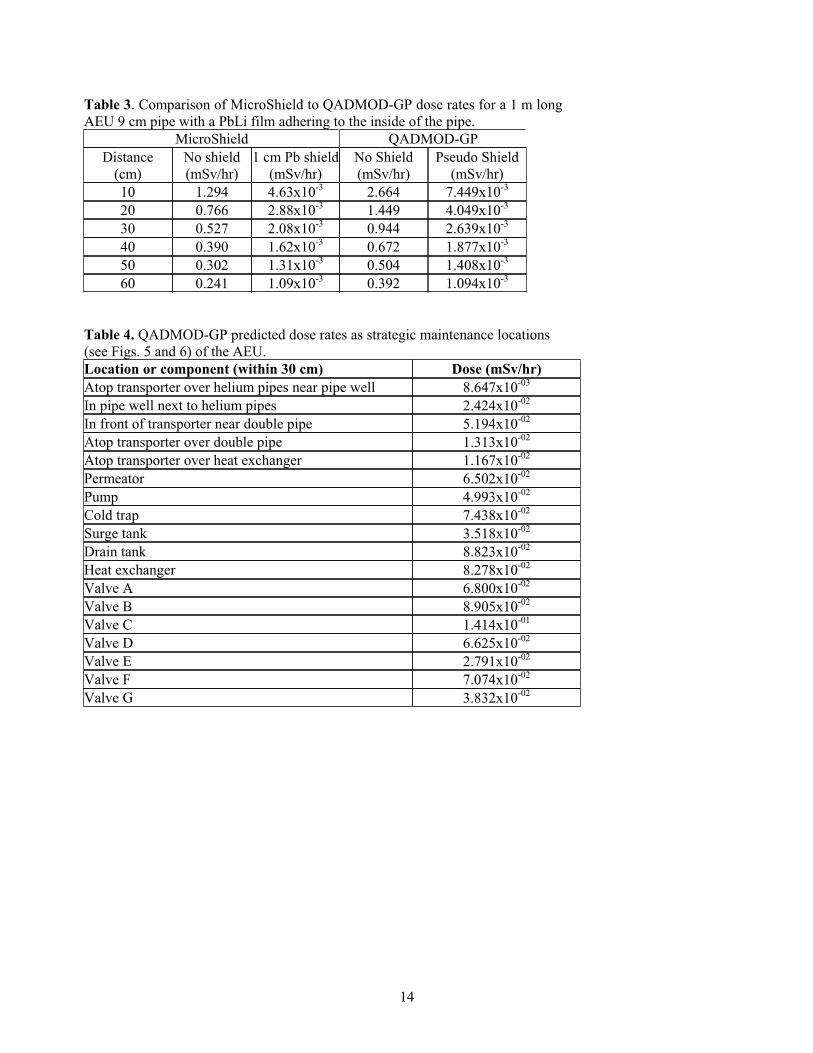
With the source terms now defined, a component by component comparison between MicroShield and QADMOD-QP was undertaken. The results for the simplest component of the AEU, which is a 9 cm diameter pipe, appear in Table 3. The MicroShield model is of a single annular source, a film on the inside surface of the pipe, and a 1 cm thick iron pipe wall. The resulting dose as a function of distance from the film appears in column one of this table. This is the effective dose equivalent (EDE) rate for the anterior/posterior human geometry, which is the highest dose rate of the five EDE geometries considered by the MicroShield code. The first item to note from this column is that the dose rate for the PbLi film alone 30 cm from the pipe wall is ~0.5 mSv/hr or 500 μSv/hr, which is a factor of 50 higher than the ITER hands on maintenance dose goal of 10 μSv/hr (Natalozio, 2005). To improve on worker safety, the design must change to include lead shielding on all of the components (e.g., 1 cm of Pb for all components, except the heat exchanger and drain tank where 2 cm and 5 cm of Pb shielding will be required). The results in column two include the attenuation from a 1 cm thick Pb shield in the MicroShield model.
The QADMOD-GP model is 10 point-kernel sources at the centerline of the pipe over a 1 m pipe section (e.g., one source per every 10 cm). The third column presents the QADMOD-GP dose prediction as a function of distance from the source terms without any shielding. In comparison to the first column, the QADMOD-GP dose rate is higher than the MicroShield dose rate (about a factor of 2.1 at 10 cm) and falls off a little faster with radial distance (a factor of 1.6 at 60 cm). Both results use the correct total source strength for the film, but the QADMOD-GP result does not include the attenuation of the pipe wall. In general though, the results are in agreement. The fourth column, labeled pseudo shield, is the QADMOD-GP result with the point-kernel source strength adjusted to match, within reason, the MicroShield dose rate at 60 cm. The reason for adopting 60 cm can be seen from Figure 4, where the width of AEU is approximately this distance. This “tuned” source strength was used to simulate all of the single piping of the AEU in this multiple point-kernel source QADMOD-GP AEU model (Figure 4). All of the QADMOD-GP source terms representing the components of the AEU were adjusted component by component to obtain the MicroShield dose rate at 60 cm. In total, the QADMOD-GP model included 245 point-kernel gamma source terms to model the entire AEU. It should be mentioned that this approach will be conservative with respect to MicroShield predictions because all maintenance doses in this study are estimate at 30 cm from the component. In the comparison of Table 3, the QADMOD-GP dose rate is higher than that of MicroShield for distances less than 60 cm.
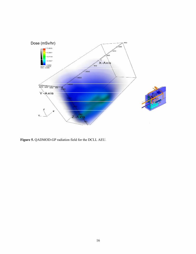
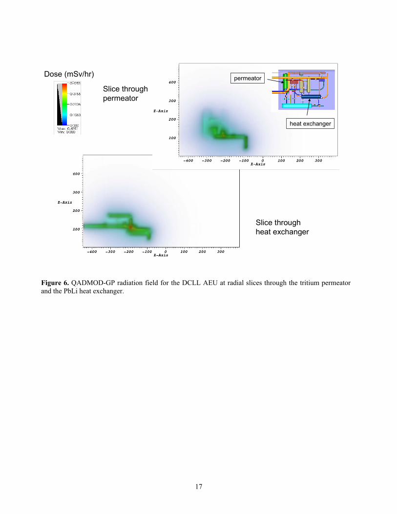
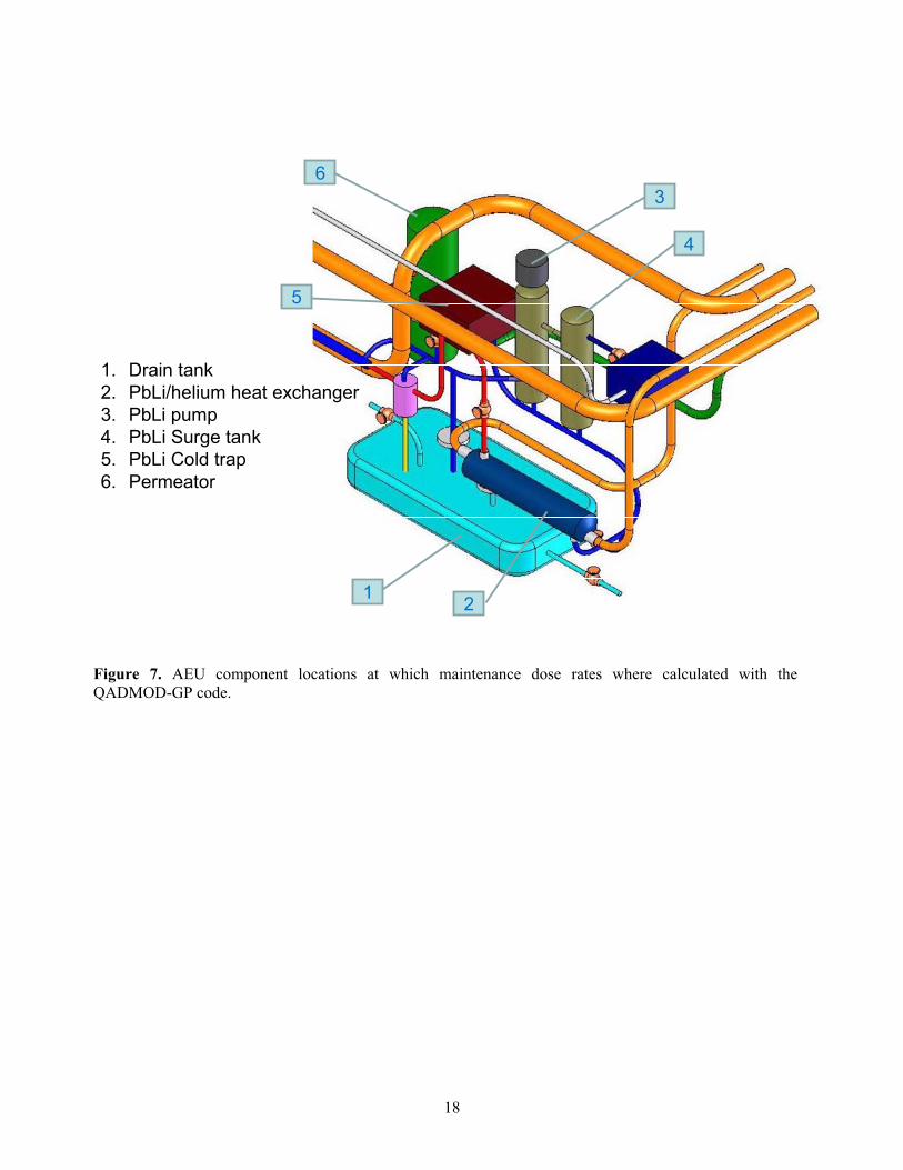
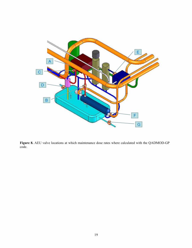
The results from multiple point-kernel source QADMOD-GP AEU model are presented in Figures 5 and 6 and in Table 4. Figure 5 contains a plot of the three-dimensional radiation (dose rate in mSv/hr) field given off by the AEU. Figure 6 contains plots of the same information at a two-dimensional R-Z slice through the AEU at the toroidal location of the tritium permeator and the PbLi heat exchanger. Finally, Table 4 tabulates the predicted dose rate at strategic maintenance locations in and around the AEU. These dose rates will be used to calculate the ORE estimates that are given in the following section of this report. These locations are identified in Figures 7 and 8.
14
Table 3. Comparison of MicroShield to QADMOD-GP dose rates for a 1 m long AEU 9 cm pipe with a PbLi film adhering to the inside of the pipe.
MicroShield QADMOD-GP Distance
(cm) No shield (mSv/hr)
1 cm Pb shield(mSv/hr)
No Shield (mSv/hr)
Pseudo Shield (mSv/hr)
10 1.294 4.63x10⁻³ 2.664 7.449x10⁻³
20 0.766 2.88x10⁻³ 1.449 4.049x10⁻³
30 0.527 2.08x10⁻³ 0.944 2.639x10⁻³
40 0.390 1.62x10⁻³ 0.672 1.877x10⁻³
50 0.302 1.31x10⁻³ 0.504 1.408x10⁻³
60 0.241 1.09x10⁻³ 0.392 1.094x10⁻³
Table 4. QADMOD-GP predicted dose rates as strategic maintenance locations (see Figs. 5 and 6) of the AEU. Location or component (within 30 cm) Dose (mSv/hr)Atop transporter over helium pipes near pipe well 8.647x10-03
In pipe well next to helium pipes 2.424x10-02
In front of transporter near double pipe 5.194x10-02
Atop transporter over double pipe 1.313x10-02
Atop transporter over heat exchanger 1.167x10-02
Permeator 6.502x10-02
Pump 4.993x10-02
Cold trap 7.438x10-02
Surge tank 3.518x10-02
Drain tank 8.823x10-02
Heat exchanger 8.278x10-02
Valve A 6.800x10-02
Valve B 8.905x10-02
Valve C 1.414x10-01
Valve D 6.625x10-02
Valve E 2.791x10-02
Valve F 7.074x10-02
Valve G 3.832x10-02
15
Center point coordinates relative to ITER Center point
X= 20400 mmY= -1300 mmZ= 0
Height (cm)
Toroidal distance (cm)
Radial dista
nce(cm
)
Height (cm
)
Figure 4. Illustration of QADMOD-GP source terms locations used to model the DCLL AEU.
16
Dose (mSv/hr)
Figure 5. QADMOD-GP radiation field for the DCLL AEU.
17
Dose (mSv/hr)
Slice through permeator
Slice through heat exchanger
permeator
heat exchanger
Figure 6. QADMOD-GP radiation field for the DCLL AEU at radial slices through the tritium permeator and the PbLi heat exchanger.
18
1 2
3
4
5
6
1. Drain tank2. PbLi/helium heat exchanger3. PbLi pump4. PbLi Surge tank5. PbLi Cold trap6. Permeator
Figure 7. AEU component locations at which maintenance dose rates where calculated with the QADMOD-GP code.
19
B
F
G
E
A
C
D
Figure 8. AEU valve locations at which maintenance dose rates where calculated with the QADMOD-GP code.
20
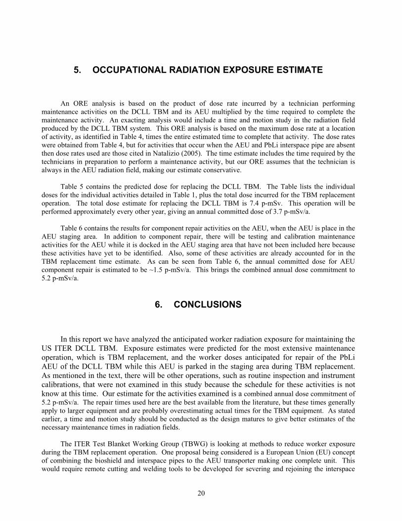
5. OCCUPATIONAL RADIATION EXPOSURE ESTIMATE
An ORE analysis is based on the product of dose rate incurred by a technician performing maintenance activities on the DCLL TBM and its AEU multiplied by the time required to complete the maintenance activity. An exacting analysis would include a time and motion study in the radiation field produced by the DCLL TBM system. This ORE analysis is based on the maximum dose rate at a location of activity, as identified in Table 4, times the entire estimated time to complete that activity. The dose rates were obtained from Table 4, but for activities that occur when the AEU and PbLi interspace pipe are absent then dose rates used are those cited in Natalizio (2005). The time estimate includes the time required by the technicians in preparation to perform a maintenance activity, but our ORE assumes that the technician is always in the AEU radiation field, making our estimate conservative.
Table 5 contains the predicted dose for replacing the DCLL TBM. The Table lists the individual doses for the individual activities detailed in Table 1, plus the total dose incurred for the TBM replacement operation. The total dose estimate for replacing the DCLL TBM is 7.4 p-mSv. This operation will be performed approximately every other year, giving an annual committed dose of 3.7 p-mSv/a.
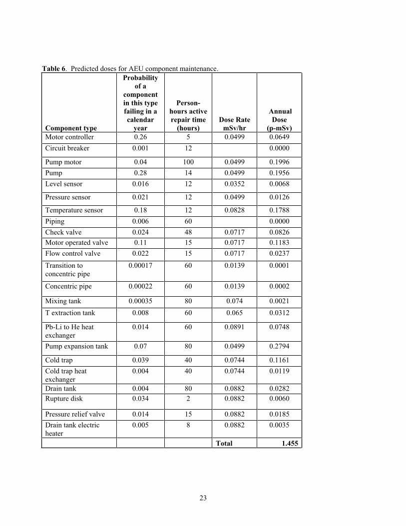
Table 6 contains the results for component repair activities on the AEU, when the AEU is place in the AEU staging area. In addition to component repair, there will be testing and calibration maintenance activities for the AEU while it is docked in the AEU staging area that have not been included here because these activities have yet to be identified. Also, some of these activities are already accounted for in the TBM replacement time estimate. As can be seen from Table 6, the annual committed dose for AEU component repair is estimated to be ~1.5 p-mSv/a. This brings the combined annual dose commitment to 5.2 p-mSv/a.
6. CONCLUSIONS
In this report we have analyzed the anticipated worker radiation exposure for maintaining the US ITER DCLL TBM. Exposure estimates were predicted for the most extensive maintenance operation, which is TBM replacement, and the worker doses anticipated for repair of the PbLi AEU of the DCLL TBM while this AEU is parked in the staging area during TBM replacement. As mentioned in the text, there will be other operations, such as routine inspection and instrument calibrations, that were not examined in this study because the schedule for these activities is not know at this time. Our estimate for the activities examined is a combined annual dose commitment of 5.2 p-mSv/a. The repair times used here are the best available from the literature, but these times generally apply to larger equipment and are probably overestimating actual times for the TBM equipment. As stated earlier, a time and motion study should be conducted as the design matures to give better estimates of the necessary maintenance times in radiation fields.
The ITER Test Blanket Working Group (TBWG) is looking at methods to reduce worker exposure during the TBM replacement operation. One proposal being considered is a European Union (EU) concept of combining the bioshield and interspace pipes to the AEU transporter making one complete unit. This would require remote cutting and welding tools to be developed for severing and rejoining the interspace
21
pipes to the TBM at the Vacuum Vessel (VV) port flange location. By doing this, the predicted dose for replacing the DCLL TBM would be reduced by nearly one half to 3.8 p-mSv, or an annual committed dose of 1.9 p-mSv/a. The combined annual dose commitment would also drop to 3.4 p-mSv/a. This reduction would be a benefit to ITER Operations since the ITER ORE goal for TBM maintenance is ~1% of the annual maintenance dose for the ITER device. The predicted value for this dose is 178 p-mSv/a (Natalizio, 2005), making the goal for DCLL TBM maintenance ~1.8 p-mSv/a. Therefore, additional effort will be required during the final design phase of the DCLL TBM to reduce the ORE dose by one half in order to achieve the ITER goal of 1.8 p-mSv/a, since the combined dose of maintenance activities for this TBM is at best 3.4 p-mSv/a even with the EU proposal. Other approaches to reduce ORE include greater effort at leaving behind less film when draining the Pb-17Li loop to its drain tank, corrosion product traps, and use of temporary shielding during maintenance activities.
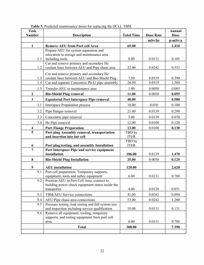
22
Table 5. Predicted maintenance doses for replacing the DCLL TBM. Task
Number Description Total Time Dose Rate Annual
DosemSv/hr p-mSv/a
1 Remove AEU from Port cell Area 65.00 2.410
1.1
Prepare AEU for system separation and relocation to storage and maintenance area including tools. 8.00 0.0131 0.105
1.2Cut and remove primary and secondary He coolant lines between AEU and Pipe chase area 22.00 0.0242 0.533
1.3Cut and remove primary and secondary He coolant lines between AEU and Bio-Shield Plug 7.50 0.0519 0.390
1.4 Cut and separate Concentric Pb-Li pipe assembly 26.50 0.0519 1.380 1.5 Transfer AEU to maintenance area 1.00 0.0050 0.005
2 Bio-Shield Plug removal 11.00 0.0050 0.055 3 Equatorial Port Interspace Pipe removal 48.00 0.580
3.1 Interspace Preparation process 10.00 0.010 0.100
3.2 Pipe Hanger removal 21.00 0.0139 0.290 3.3 Concentric pipe removal 5.00 0.0139 0.070 3.4 He Pipe removal 12.00 0.0100 0.120
4 Port Flange Preparation 13.00 0.0100 0.130 5 Port plug Assembly removal, transportation
and insertion into hot cell TBD by
ITER
6 Port plug testing, and assembly Installation TBD by
ITER7 Port Interspace Pipe and service equipment
Installation 106.00 0.0139 1.470 8 Bio-Shield Plug Installation 25.00 0.0050 0.125
9 AEU installation 120.00 2.620 9.1 Port cell preparation. Temporary supports,
equipment, tools and saftey equipment 6.00 0.0131 0.788 9.2 Position AEU in Port Cell Area, connect to
building power check equipment status inside the transporter. 4.00 0.0128 0.051
9.3 TBM/AEU Service connections 41.00 0.0242 0.994 9.4 AEU/Pipe chase area connections 53.00 0.0242 1.280 9.5 Pressure testing, leak testing and full system test
and inspection including service qualification 10.00 0.0131 0.131 9.6 Remove all equipment, tooling, temporary
supports, and testing equipment from port cell area. 6.00 0.0131 0.788
Total 388.00 7.390
23
Table 6. Predicted doses for AEU component maintenance.
Component type
Probabilityof a
componentin this type failing in a calendar
year
Person-hours active repair time
(hours)Dose Rate
mSv/hr
Annual Dose
(p-mSv)Motor controller 0.26 5 0.0499 0.0649 Circuit breaker 0.001 12 0.0000
Pump motor 0.04 100 0.0499 0.1996 Pump 0.28 14 0.0499 0.1956 Level sensor 0.016 12 0.0352 0.0068
Pressure sensor 0.021 12 0.0499 0.0126
Temperature sensor 0.18 12 0.0828 0.1788 Piping 0.006 60 0.0000 Check valve 0.024 48 0.0717 0.0826 Motor operated valve 0.11 15 0.0717 0.1183 Flow control valve 0.022 15 0.0717 0.0237
Transition to concentric pipe
0.00017 60 0.0139 0.0001
Concentric pipe 0.00022 60 0.0139 0.0002
Mixing tank 0.00035 80 0.074 0.0021 T extraction tank 0.008 60 0.065 0.0312
Pb-Li to He heat exchanger
0.014 60 0.0891 0.0748
Pump expansion tank 0.07 80 0.0499 0.2794
Cold trap 0.039 40 0.0744 0.1161 Cold trap heat exchanger
0.004 40 0.0744 0.0119
Drain tank 0.004 80 0.0882 0.0282 Rupture disk 0.034 2 0.0882 0.0060
Pressure relief valve 0.014 15 0.0882 0.0185 Drain tank electric heater
0.005 8 0.0882 0.0035
Total 1.455
24
7. REFERENCES
Butler, 2000. D. Butler, Guide to Ship Repair Estimates (in Man-Hours), Butterworth Heinemann, Amsterdam, 2000.
Cadwallader, 2007. L. C. Cadwallader, Preliminary Failure Modes and Effects Analysis of the US Test Blanket Module, INL-EXT-07-13115, August 2007.
Cavagna, 2006. Ch. Cavagna, O. Gastaldi, L. Martin, and V. Grabon, “Phenix Steam Generator Module Repair: Sodium Removal Process, Ultrasonic Controls, and Repair Method,” Nuclear Technology,153 (2006) 274-281.
Chilton, 2007. Chilton Labor Guide Manual, 2007 edition, Thomson Delmar Learning, Clifton Park, NY, 2007.
Cullinane, 1989. M. J. Cullinane, Jr., “Reliability and Maintainability Data for Water Distribution System Components,” in L.W. Mays, editor, Reliability Analysis of Water Distribution Systems, American Society of Civil Engineers, New York, 1989, pages 225-246.
Feuerstein, 1999. H. Feuerstein, S. Horn and G. Kieser, TRITEX – A ferritic Steel Loop with Pb-15.8Li Facility and Operation, Forschungszentrun Karlsruhe Report, FZHA 6286, May (1999).
Isozaki, 2005. K. Isozaki, T. Ashida, K. Sumino, and S. Nakai, “Upgrade of Cooling System Heat Removal Capacity of the Experimental Fast Reactor JOYO,” Nuclear Technology, 150 (2005) 56-66.
Matthews, 1968. R. R. Matthews and K. J. Henry, “Location and repair of the DFR leak,” Nuclear Engineering, 13 (1968) 840-844.
Means, 2007. Building Construction Cost Data 2007, sixty-fifth edition, RS Means Company, Kingston, MA, 2007.
MicroShield, 2006. User's Manual, Ver. 6.21, Grove Software, Inc, Lynchburg, VA, March (2006) – www.radiationsoftware.com.
MIL, 1988. Maintainability Design Techniques, DOD-HDBK-791, US Department of Defense, Washington, DC, March 1988.
Milivojevic, 1989. S. Milivojevic and J. R. Riznic, “The Empirical Failure Rate and Repair Rate of PWR Primary Coolant Pumps,” Reliability Engineering and System Safety, 24 (1989) 267-273.
Moriyama, 1995. H. Moriyama, et al., “Tritium Recovery from Liquid Metals,” Fusion Engineering and Design, 28, 1995, p. 226-239.
Natalizio, 2005. A. Natalizo, M. T. Porfiri, Revison of the ORE assessment for the Port-Interfacing Systems, ENEA Report, FUS-TN-SA-SE-R-140, December (2005).
Olson, 1986. W. H. Olson, “The Impact of Radionuclides on Maintenance of Experimental Breeder Reactor II,” Argonne National Laboratory, CONF-860311-1, presented at the American Nuclear
25
Society Topical Meeting on Nuclear Power Plant Maintenance, Salt Lake City, Utah, March 23-27, 1986.
Shultz, 1982. D. W. Shultz and V. B. Parr, Evaluation and Documentation of Mechanical Reliability of Conventional Wastewater Treatment Plant Components, EPA-600/2-82-044, accession number PB82227539, US Environmental Protection Agency, Cincinnati, Ohio, March 1982.
Warkentin, 1990. J. K. Warkentin, Utilization Instructions for QADMOD-GP – A PC Verions of QADMOD-G with Geometric Progression Buildup Factors, RSIC Code Package CCC-565, November (1990).
Wong, 2005. C. P. C. Wong, et al., Design Description Document for the U. S. Dual Coolant Pb-17Li (DCLL) Test Blanket Module, General Atomics Report, GA-C25027, Rev. 3, November 15 (2005).

26
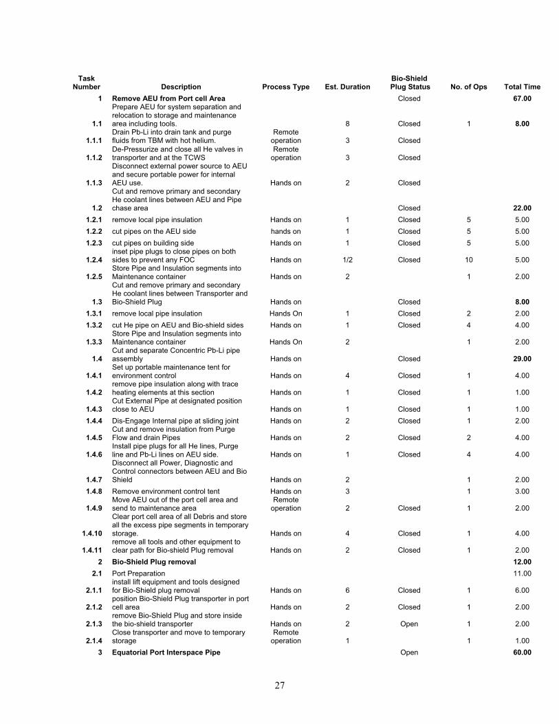
Appendix A
Detail Time Estimate for Replacing the DCLL TBM
27
TaskNumber Description Process Type Est. Duration
Bio-Shield Plug Status No. of Ops Total Time
1 Remove AEU from Port cell Area Closed 67.00
1.1
Prepare AEU for system separation and relocation to storage and maintenance area including tools. 8 Closed 1 8.00
1.1.1Drain Pb-Li into drain tank and purge fluids from TBM with hot helium.
Remoteoperation 3 Closed
1.1.2De-Pressurize and close all He valves in transporter and at the TCWS
Remoteoperation 3 Closed
1.1.3
Disconnect external power source to AEU and secure portable power for internal AEU use. Hands on 2 Closed
1.2
Cut and remove primary and secondary He coolant lines between AEU and Pipe chase area Closed 22.00
1.2.1 remove local pipe insulation Hands on 1 Closed 5 5.00 1.2.2 cut pipes on the AEU side hands on 1 Closed 5 5.00 1.2.3 cut pipes on building side Hands on 1 Closed 5 5.00
1.2.4inset pipe plugs to close pipes on both sides to prevent any FOC Hands on 1/2 Closed 10 5.00
1.2.5Store Pipe and Insulation segments into Maintenance container Hands on 2 1 2.00
1.3
Cut and remove primary and secondary He coolant lines between Transporter and Bio-Shield Plug Hands on Closed 8.00
1.3.1 remove local pipe insulation Hands On 1 Closed 2 2.00 1.3.2 cut He pipe on AEU and Bio-shield sides Hands on 1 Closed 4 4.00
1.3.3Store Pipe and Insulation segments into Maintenance container Hands On 2 1 2.00
1.4Cut and separate Concentric Pb-Li pipe assembly Hands on Closed 29.00
1.4.1Set up portable maintenance tent for environment control Hands on 4 Closed 1 4.00
1.4.2remove pipe insulation along with trace heating elements at this section Hands on 1 Closed 1 1.00
1.4.3Cut External Pipe at designated position close to AEU Hands on 1 Closed 1 1.00
1.4.4 Dis-Engage Internal pipe at sliding joint Hands on 2 Closed 1 2.00
1.4.5Cut and remove insulation from Purge Flow and drain Pipes Hands on 2 Closed 2 4.00
1.4.6Install pipe plugs for all He lines, Purge line and Pb-Li lines on AEU side. Hands on 1 Closed 4 4.00
1.4.7
Disconnect all Power, Diagnostic and Control connectors between AEU and Bio Shield Hands on 2 1 2.00
1.4.8 Remove environment control tent Hands on 3 1 3.00
1.4.9Move AEU out of the port cell area and send to maintenance area
Remoteoperation 2 Closed 1 2.00
1.4.10
Clear port cell area of all Debris and store all the excess pipe segments in temporary storage. Hands on 4 Closed 1 4.00
1.4.11remove all tools and other equipment to clear path for Bio-shield Plug removal Hands on 2 Closed 1 2.00
2 Bio-Shield Plug removal 12.002.1 Port Preparation 11.00
2.1.1install lift equipment and tools designed for Bio-Shield plug removal Hands on 6 Closed 1 6.00
2.1.2position Bio-Shield Plug transporter in port cell area Hands on 2 Closed 1 2.00
2.1.3remove Bio-Shield Plug and store inside the bio-shield transporter Hands on 2 Open 1 2.00
2.1.4Close transporter and move to temporary storage
Remoteoperation 1 1 1.00
3 Equatorial Port Interspace Pipe Open 60.00
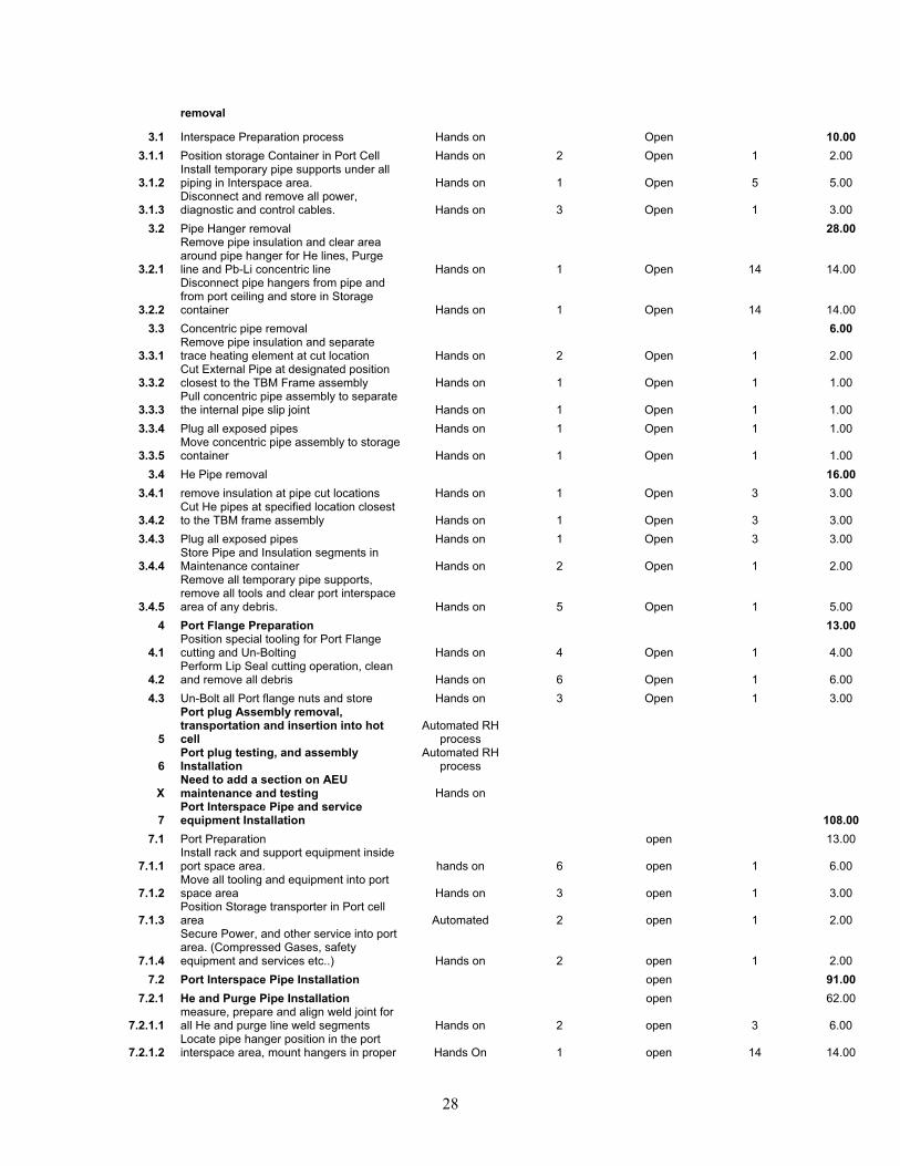
28
removal
3.1 Interspace Preparation process Hands on Open 10.003.1.1 Position storage Container in Port Cell Hands on 2 Open 1 2.00
3.1.2Install temporary pipe supports under all piping in Interspace area. Hands on 1 Open 5 5.00
3.1.3Disconnect and remove all power, diagnostic and control cables. Hands on 3 Open 1 3.00
3.2 Pipe Hanger removal 28.00
3.2.1
Remove pipe insulation and clear area around pipe hanger for He lines, Purge line and Pb-Li concentric line Hands on 1 Open 14 14.00
3.2.2
Disconnect pipe hangers from pipe and from port ceiling and store in Storage container Hands on 1 Open 14 14.00
3.3 Concentric pipe removal 6.00
3.3.1Remove pipe insulation and separate trace heating element at cut location Hands on 2 Open 1 2.00
3.3.2Cut External Pipe at designated position closest to the TBM Frame assembly Hands on 1 Open 1 1.00
3.3.3Pull concentric pipe assembly to separate the internal pipe slip joint Hands on 1 Open 1 1.00
3.3.4 Plug all exposed pipes Hands on 1 Open 1 1.00
3.3.5Move concentric pipe assembly to storage container Hands on 1 Open 1 1.00
3.4 He Pipe removal 16.003.4.1 remove insulation at pipe cut locations Hands on 1 Open 3 3.00
3.4.2Cut He pipes at specified location closest to the TBM frame assembly Hands on 1 Open 3 3.00
3.4.3 Plug all exposed pipes Hands on 1 Open 3 3.00
3.4.4Store Pipe and Insulation segments in Maintenance container Hands on 2 Open 1 2.00
3.4.5
Remove all temporary pipe supports, remove all tools and clear port interspace area of any debris. Hands on 5 Open 1 5.00
4 Port Flange Preparation 13.00
4.1Position special tooling for Port Flange cutting and Un-Bolting Hands on 4 Open 1 4.00
4.2Perform Lip Seal cutting operation, clean and remove all debris Hands on 6 Open 1 6.00
4.3 Un-Bolt all Port flange nuts and store Hands on 3 Open 1 3.00
5
Port plug Assembly removal, transportation and insertion into hot cell
Automated RH process
6Port plug testing, and assembly Installation
Automated RH process
XNeed to add a section on AEU maintenance and testing Hands on
7Port Interspace Pipe and service equipment Installation 108.00
7.1 Port Preparation open 13.00
7.1.1Install rack and support equipment inside port space area. hands on 6 open 1 6.00
7.1.2Move all tooling and equipment into port space area Hands on 3 open 1 3.00
7.1.3Position Storage transporter in Port cell area Automated 2 open 1 2.00
7.1.4
Secure Power, and other service into port area. (Compressed Gases, safety equipment and services etc..) Hands on 2 open 1 2.00
7.2 Port Interspace Pipe Installation open 91.007.2.1 He and Purge Pipe Installation open 62.00
7.2.1.1measure, prepare and align weld joint for all He and purge line weld segments Hands on 2 open 3 6.00
7.2.1.2Locate pipe hanger position in the port interspace area, mount hangers in proper Hands On 1 open 14 14.00
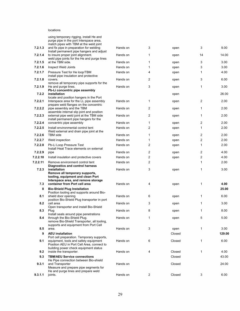
29
locations
7.2.1.3
using temporary rigging, install He and purge pipe in the port Interspace area, match pipes with TBM at the weld joint and fix pipe in preparation for welding Hands on 3 open 3 9.00
7.2.1.4Install permanent pipe hangers and adjust to insure proper joint alignment. Hands on 1 open 14 14.00
7.2.1.5weld pipe joints for the He and purge lines at the TBM side. Hands on 1 open 3 3.00
7.2.1.6 Inspect Weld Joints Hands on 1 open 3 3.00 7.2.1.7 Pressure Test for He loop/TBM Hands on 4 open 1 4.00
7.2.1.8install pipe insulation and protective covers. Hands on 2 open 3 6.00
7.2.1.9remove all temporary pipe supports for the He and purge lines. Hands on 3 open 1 3.00
7.2.2Pb-Li concentric pipe assembly installation open 26.00
7.2.2.1locate and position hangers in the Port Interspace area for the LL pipe assembly Hands on 1 open 2 2.00
7.2.2.2prepare weld flanges on the concentric pipe assembly and the TBM Hands on 2 open 1 2.00
7.2.2.3assemble internal slip joint and position external pipe weld joint at the TBM side Hands on 2 open 1 2.00
7.2.2.4install permanent pipe hangers for the concentric pipe assembly Hands on 1 open 2 2.00
7.2.2.5 Install environmental control tent Hands on 2 open 1 2.00
7.2.2.6Weld external and drain pipe joint at the TBM side Hands on 1 open 2 2.00
7.2.2.7 Weld inspection Hands on 1 open 2 2.00 7.2.2.8 Pb-Li Loop Pressure Test Hands on 2 open 1 2.00
7.2.2.9Install Heat Trace elements on external pipe Hands on 2 open 2 4.00
7.2.2.10 Install insulation and protective covers Hands on 2 open 2 4.00 7.2.2.11 Remove environment control tent Hands on 2 1 2.00
7.2.3Diagnostics and control harness installation Hands on 3 open 1 3.00
7.3
Remove all temporary supports, tooling, equipment and clean Port Interspace area, and remove storage container from Port cell area Hands on 4 open 1 4.00
8 Bio-Shield Plug Installation 25.00
8.1Position tooling and supports around Bio-shield door opening Hands on 6 open 1 6.00
8.2position Bio-Shield Plug transporter in port cell area Hands on 3 open 1 3.00
8.3Open transporter and install Bio-Shield Plug Hands on 8 open 1 8.00
8.4Install seals around pipe penetrations through the Bio-Shield Plug. Hands on 1 open 5 5.00
8.5
remove Bio-Shield Transporter, all tooling, supports and equipment from Port Cell area. Hands on 3 open 1 3.00
9 AEU installation Closed 129.00
9.1Port cell preparation. Temporary supports, equipment, tools and safety equipment Hands on 6 Closed 1 6.00
9.2
Position AEU in Port Cell Area, connect to building power check equipment status inside the transporter. Hands on 4 Closed 1 4.00
9.3 TBM/AEU Service connections Closed 43.00
9.3.1He Pipe connection between Bio-shield and Transporter Hands on Closed 24.00
9.3.1.1
Measure and prepare pipe segments for He and purge lines and prepare weld joints. Hands on 2 Closed 3 6.00
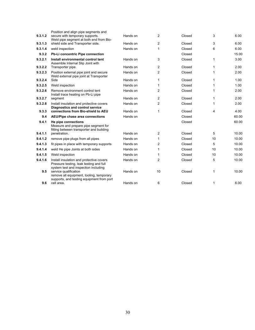
30
9.3.1.2Position and align pipe segments and secure with temporary supports. Hands on 2 Closed 3 6.00
9.3.1.3Weld pipe segment at both end from Bio-shield side and Transporter side. Hands on 2 Closed 3 6.00
9.3.1.4 weld inspection Hands on 1 Closed 6 6.00 9.3.2 Pb-Li concentric Pipe connection Closed 15.00
9.3.2.1 Install environmental control tent Hands on 3 Closed 1 3.00
9.3.2.2Assemble Internal Slip Joint with Transporter pipe. Hands on 2 Closed 1 2.00
9.3.2.3 Position external pipe joint and secure Hands on 2 Closed 1 2.00
9.3.2.4Weld external pipe joint at Transporter Side Hands on 1 Closed 1 1.00
9.3.2.5 Weld inspection Hands on 1 Closed 1 1.00 9.3.2.6 Remove environment control tent Hands on 2 Closed 1 2.00
9.3.2.7Install trace heating on Pb-Li pipe segment Hands on 2 Closed 1 2.00
9.3.2.8 Install insulation and protective covers Hands on 2 Closed 1 2.00
9.3.3Diagnostics and control service connections from Bio-shield to AEU Hands on 1 Closed 4 4.00
9.4 AEU/Pipe chase area connections Hands on Closed 60.00 9.4.1 He pipe connections Closed 60.00
9.4.1.1
Measure and prepare pipe segment for fitting between transporter and building penetration. Hands on 2 Closed 5 10.00
9.4.1.2 remove pipe plugs from all pipes Hands on 1 Closed 10 10.00 9.4.1.3 fit pipes in place with temporary supports Hands on 2 Closed 5 10.00 9.4.1.4 weld He pipe Joints at both sides Hands on 1 Closed 10 10.00 9.4.1.5 Weld inspection Hands on 1 Closed 10 10.00 9.4.1.6 Install insulation and protective covers Hands on 2 Closed 5 10.00
9.5
Pressure testing, leak testing and full system test and inspection including service qualification Hands on 10 Closed 1 10.00
9.6
remove all equipment, tooling, temporary supports, and testing equipment from port cell area. Hands on 6 Closed 1 6.00