Embed Size (px)
Citation preview
Organic Light Emitting Diodes
for lightening (WOLEDs)
ORGANIC ELECTRONICS : principles, devices and applications
Chiara Botta, ISMAC, CNR via Bassini 15, 20133 [email protected]
WOLEDs
Emitting species:Singlet and Triplet exciton, excimer, exciplex
Conclusion and outlooks
Materials: Organic molecules and polymers, Hybrid materials
White light OLED (WOLED)
•White light: fundamental parameters (efficiency, CIE, CRI)
OUTLINE
•White light with molecules, polymers and hybrid systems
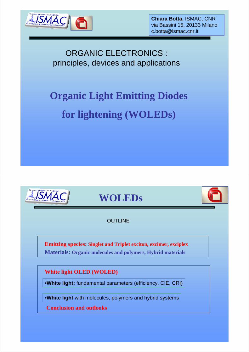
ELETTROLUMINESCENCE
+ -1-+
1
1.Injection
+ -3
3.Exciton Formation
4 4.Emission
2
2
2.Transport
ITO
HOMO
LUMO
vacuum
1
+
-1
metal
φm
φITO IP
EA
∆∆∆∆e
∆∆∆∆h
2
3
24
-
+
P-
P+ hννννΦ metals should fit theHOMO and LUMOlevels
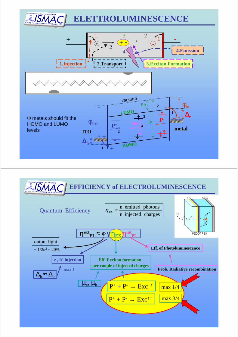
ηηηηextEL ≈≈≈≈ Φ Φ Φ Φ γγγγ ηηηηEX ηηηηint
PL
Eff. of Photoluminescence
Eff. Exciton formation per couple of injected charges
µe, µh
∆h ≈≈≈≈ ∆e
e-, h+ injection
max 1
Quantum Efficiencycharges injected n.
photons emitted n.≡ELη
Prob. Radiative recombination
output light
~ 1/2n2 ~ 20%
P+ + P- → Exc↓↑ max 1/4
P+ + P- → Exc↑↑ max 3/4
EFFICIENCY of ELECTROLUMINESCENCE
Th
S0
S1
S2
10-12secIC
S0
S1
S2
10-9
secFluorescence
ISC
10-3
sec
Phosphorescence
S0
T
Tn
10-15 Absorption
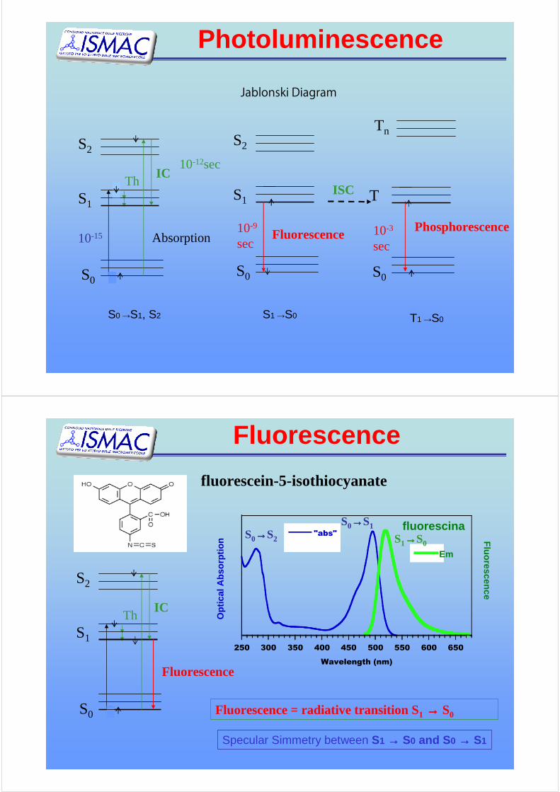
Photoluminescence
Jablonski Diagram
S0 →S1, S2 S1 →S0 T1 →S0
fluorescein-5-isothiocyanate
Th
S0
S1
S2
IC
Fluorescence
250 300 350 400 450 500 550 600 650
fluorescina"abs"
Opt
ical
Abs
orpt
ion
Wavelength (nm)
S0→→→→S2
S0→→→→S1
Fluorescence
Em
S1→→→→S0
Fluorescence = radiative transition S1 →→→→ S0
Specular Simmetry between S1 →→→→ S0 and S0 →→→→ S1
Fluorescence
S0
S1
S2
ISC
S0
T1
Phosphorescence
S(H2C)11
O
OO
F3C
N
NEu
S
(CH2)11
Br
O
OCF3
S
(H2C)11
O
O
OCF3
Ligand Eu
300 400 500 600 700
Abs
orpt
ion E
mission
Wavelength (nm)
No specular symmetry
PhosphorescenceHeavy atom favours
Inter System CrossingISC
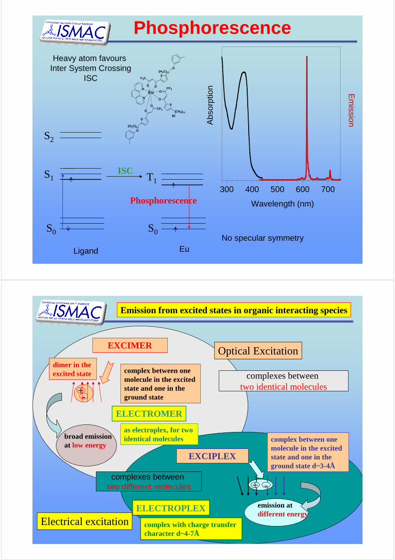
broad emissionat low energy
EXCIMER
+-
dimer in the excited state complex between one
molecule in the excitedstate and one in the ground state
complexes betweentwo identical molecules
complexes betweentwo different molecules + -
EXCIPLEX
complex between onemolecule in the excitedstate and one in the ground state d~3-4Å
ELECTROPLEX
complex with charge transfer character d~4-7Å
Emission from excited states in organic interacting species
ELECTROMER
as electroplex, for twoidentical molecules
Electrical excitation
Optical Excitation
emission at different energy
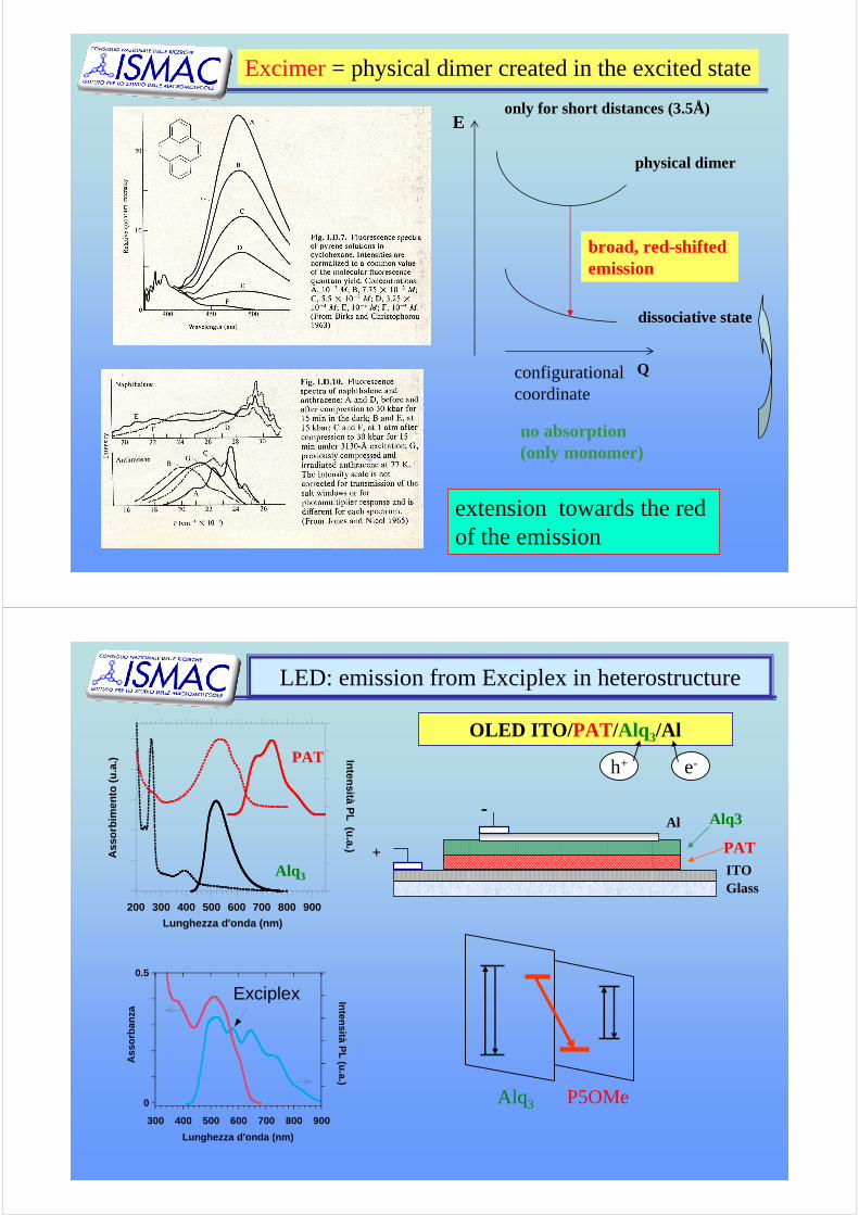
Excimer= physical dimer created in the excited state
configurationalcoordinate
Q
physical dimer
dissociative state
broad, red-shiftedemission
no absorption(only monomer)
Eonly for short distances (3.5Å)
extension towards the redof the emission
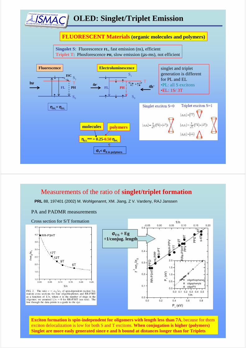
LED: emission from Exciplex in heterostructure
OLED ITO/ PAT/Alq 3/Al
h+ e-
200 300 400 500 600 700 800 900
Ass
orbi
men
to (
u.a.
)
Intensità PL (u.a.)
Lunghezza d'onda (nm)
PAT
Alq3
Al
PATITOGlass
+
-Alq3
0
0.5
300 400 500 600 700 800 900
Ass
orba
nza
Intensità PL (u.a.)
Lunghezza d'onda (nm)
Alq3 P5OMe
Exciplex
OLED: Singlet/Triplet Emission
FLUORESCENT Materials (organic molecules and polymers)
Singolet S: FluorescenceFL , fast emission (ns), efficientTriplet T : PhosforescencePH, slow emission (µs-ms), not efficient
ηηηηPL= ηηηηFL
Fluorescence
hνννν
S0
S1
T
ISC
FL PH
singlet and tripletgeneration is differentfor PL and EL •PL: all S excitons•EL: 1S/ 3T
FL PH4e-
S0
S1
T4h++< >
Electroluminescence
ηηηηELmax = 0.25-0.50ηηηηPL
polymersmolecules
σσσσT< σσσσS in polymers
Cross section for S/T formation
PA and PADMR measurements
Measurements of the ratio ofsinglet/triplet formationPRL 88, 197401 (2002) M. Wohlgenannt, XM. Jiang, Z V. Vardeny, RAJ Janssen
Exciton formation is spin-independent for oligomers with length lessthan 7A, because for themexciton delocalization is low for both S and T excitons. When conjugation is higher (polymers) Singlet are more easly generated since e and h bound at distances longer than for Triplets
σσσσT/S ÷ Eg÷1/conjug. length
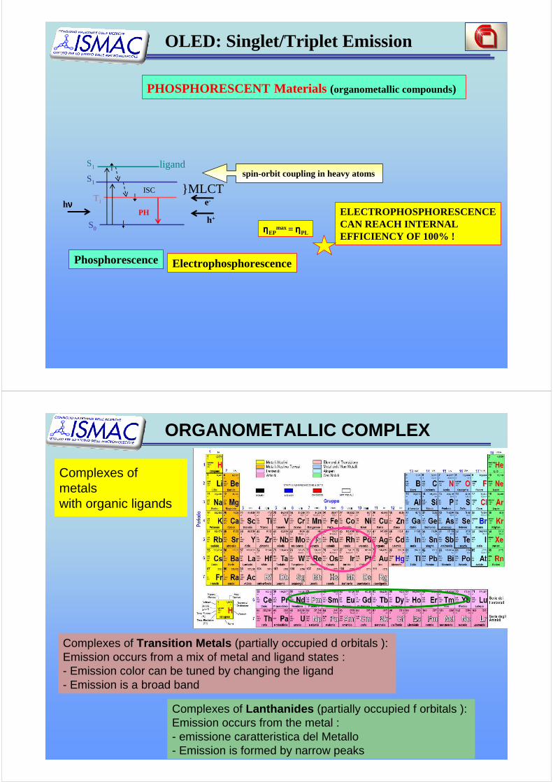
PHOSPHORESCENT Materials (organometallic compounds)
e-
h+ELECTROPHOSPHORESCENCECAN REACH INTERNAL EFFICIENCY OF 100% !
ηηηηEPmax = ηηηηPL
Electrophosphorescence
S1spin-orbit coupling in heavy atoms
}MLCT
ligand
PH
S0
S1
T1
ISC
hνννν
Phosphorescence
OLED: Singlet/Triplet Emission
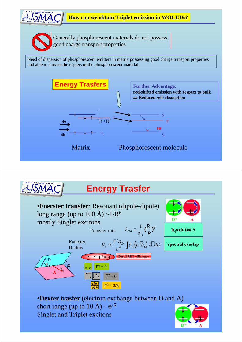
Complexes ofmetalswith organic ligands
Complexes of Transition Metals (partially occupied d orbitals ): Emission occurs from a mix of metal and ligand states : - Emission color can be tuned by changing the ligand- Emission is a broad band
Complexes of Lanthanides (partially occupied f orbitals ): Emission occurs from the metal : - emissione caratteristica del Metallo- Emission is formed by narrow peaks
ORGANOMETALLIC COMPLEX

Iridium based phosphorescentcomplexes: Emission from metal-ligand states
Complexes of transition metals
Strong spin–orbit coupling induced by heavy atom →
Efficient Inter Sistem Crossing from Singlet to Triplet: Triplet Population. -Mixing of S and T states via spin–orbit coupling relaxes the selection rule of the spin-
forbidden T1→S0 transition→ phosphorescence quantum efficiency increases
-transitions πd: LMCT (Ligand-to-Metal-Charge-Transfer): Transitions of e- from ligand statesto the metal centered orbital
•Rhenium, Ruthenium, Osmium, Rhodium, Iridium, Palladium, Platinum
Ions of transizion metal + organicligand able to coordinate the ion
Organo-Lanthanides Complexes
Partial Level Diagram of Lanthanide ionsGround statesEmitting Levels
Chem. Soc. Rev., 2005, 34, 1048.
f → f transizion are forbidden: Low absorption coefficient of Ln
Excitation occurs through the ligand: sensitization or antenna effectLigand → Ln*
NIR emittersH2O
NIR
T1 ≈ D → Back ET
Sharp emission lines of the metals
How can we obtain Triplet emission in WOLEDs?
Generally phosphorescent materials do not possessgood charge transport properties
Need of dispersion of phosphorescent emitters in matrix possessing good charge transport propertiesand able to harvest the triplets of the phosphorescent material
Phosphorescent molecule
4e-
S0
S1
T+< >
PH
S0
S1
T
4h+
Matrix
Energy Trasfers Further Advantage:red-shifted emission with respect to bulk⇒⇒⇒⇒ Reduced self-absorption
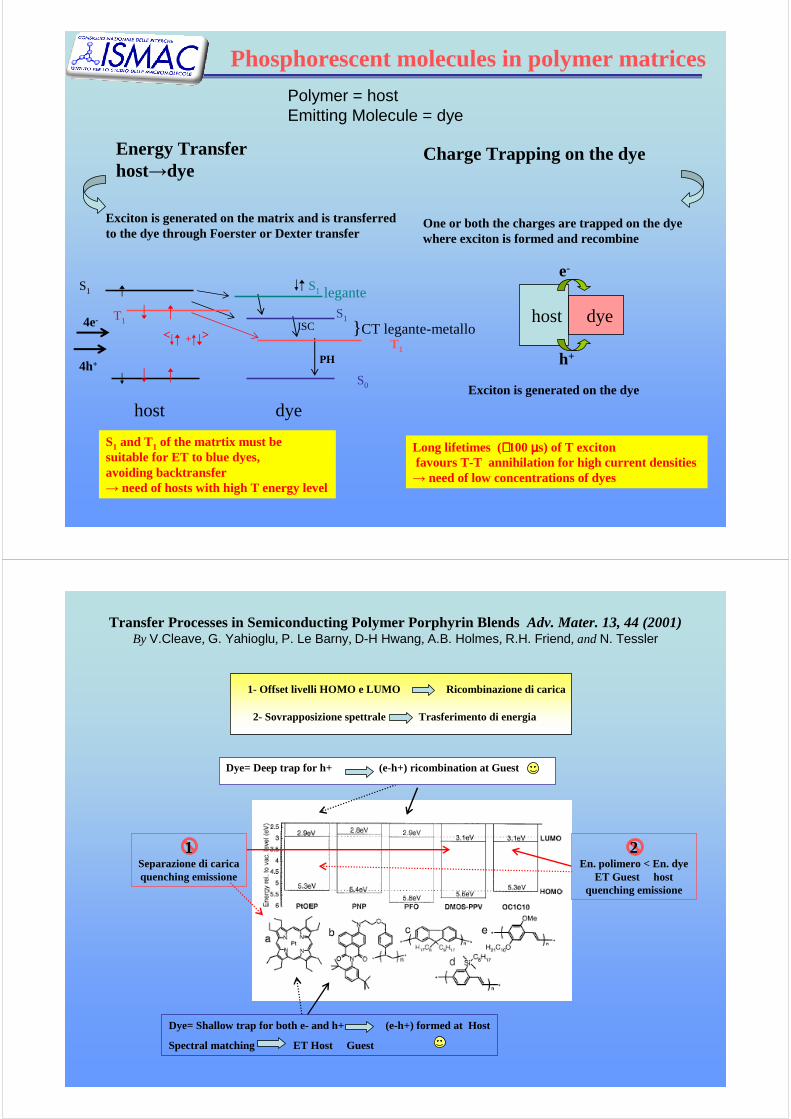
•Foerster transfer: Resonant (dipole-dipole) long range (up to 100 Å) ~1/R6
mostly Singlet excitons
•Dexter trasfer (electron exchange between D and A)short range (up to 10 Å) ~ e-R
Singlet and Triplet excitons
601)(
R
Rk
DDA τ
=Transfer rate
( ) ( )dEEFEn
R DAD
o ∫Γ≈ εη
4
2FoersterRadius
spectral overlap
R0≈≈≈≈10-100 Å
Energy Trasfer
Best FRET efficiencyD
AθA
θD φ
ΓΓΓΓ2 = 4
ΓΓΓΓ2 = 1
ΓΓΓΓ2 = 2/3
ΓΓΓΓ2 = 0
Phosphorescent molecules in polymer matrices
Energy Transferhost→dye
Exciton is generated on the matrix and is transferredto the dye through Foerster or Dexter transfer
Long lifetimes (∼∼∼∼100µµµµs) of T excitonfavours T-T annihilation for high current densities→ need of low concentrations of dyes
S1 and T1 of the matrtix must besuitable for ET to blue dyes, avoiding backtransfer→ need of hosts with high T energy level
PH
ISCS1
S0
T1
S1 legante
} CT legante-metallo
dye
S1
+< >
host
4e-
4h+
T1 host dye
h+
e-
One or both the charges are trapped on the dyewhere exciton is formed and recombine
Exciton is generated on the dye
Charge Trapping on the dye
Polymer = hostEmitting Molecule = dye
Transfer Processes in Semiconducting Polymer Porphyrin Blends Adv. Mater. 13, 44 (2001)By V.Cleave, G. Yahioglu, P. Le Barny, D-H Hwang, A.B. Holmes, R.H. Friend, and N. Tessler
1- Offset livelli HOMO e LUMO Ricombinazione di carica
2- Sovrapposizione spettrale Trasferimento di energia
Dye= Shallow trap for both e- and h+ (e-h+) formed at Host
Spectral matching ET Host� Guest
Dye= Deep trap for h+ (e-h+) ricombination at Guest
1Separazione di caricaquenching emissione
2En. polimero < En. dye
ET Guest � hostquenching emissione

WOLED
Multilayers WOLEDs ( deposition of low molecular weight molecules by thermalevaporation under vacuum)Single layerWOLED (solution processable materials)
Outlook:EL from nanostructured organic and hybrid materials ?
•White light: fundamental parameters (efficiency, CIE, CRI)
•White light with molecules, polymers and hybrid systems: -balance of emissions from Singlet and Triplet states-control of Energy Transfer
CIE (x;y) coordinatesColor is exactly identified
(0.33;0.33) white light
pure colors are on the borders
Color
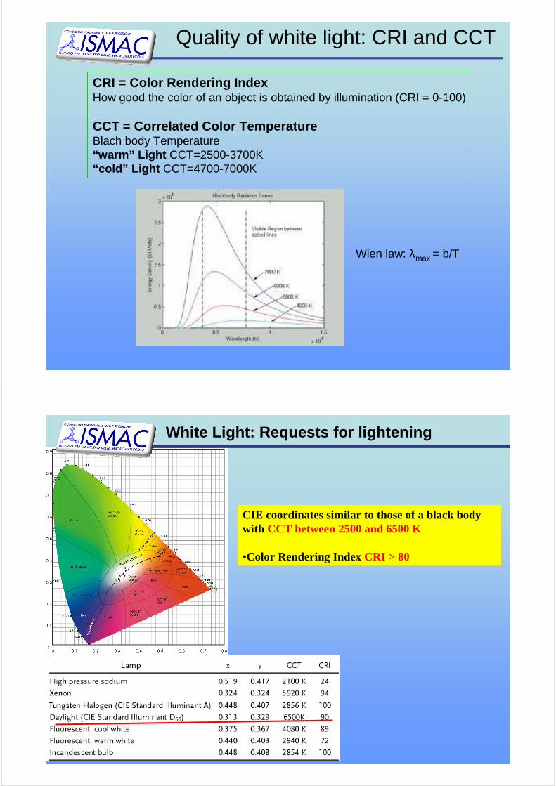
Quality of white light: CRI and CCT
CRI = Color Rendering IndexHow good the color of an object is obtained by illumination (CRI = 0-100)
CCT = Correlated Color TemperatureBlach body Temperature“warm” Light CCT=2500-3700K“cold” Light CCT=4700-7000K
Wien law: λmax = b/T
CIE coordinates similar to those of a black body with CCT between 2500 and 6500 K
•Color Rendering Index CRI > 80
White Light: Requests for lightening
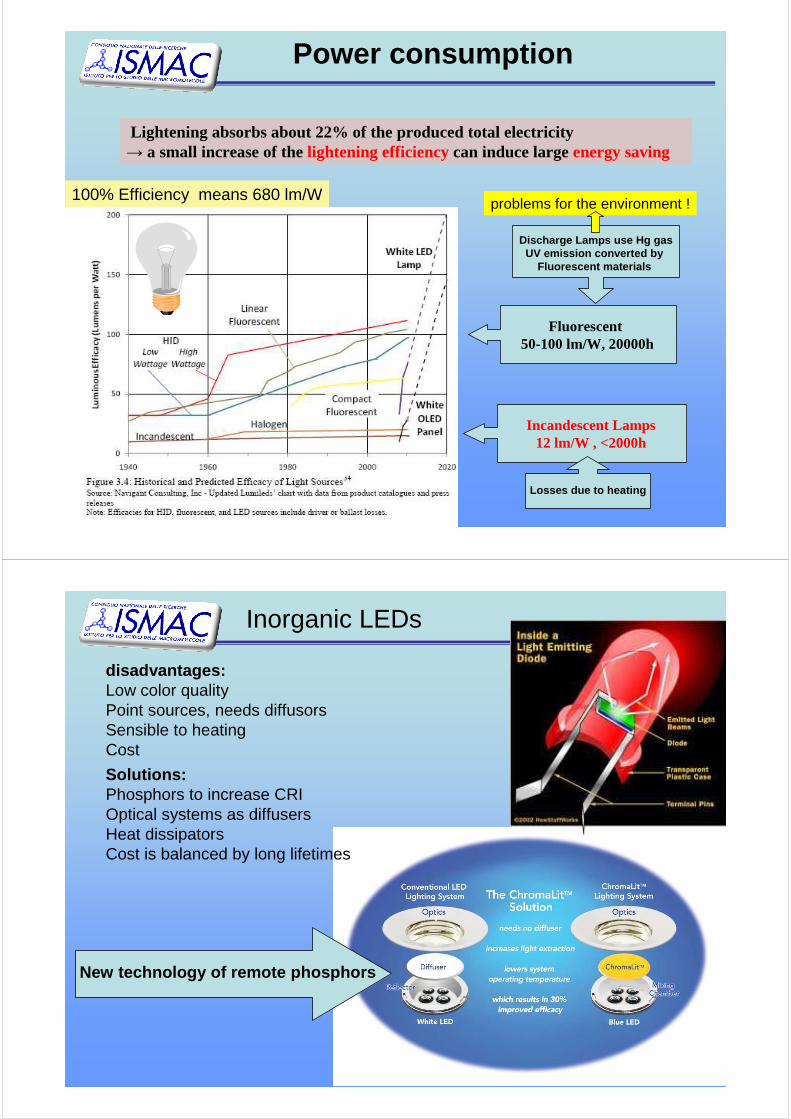
Fluorescent50-100 lm/W, 20000h
Power consumption
Lightening absorbs about 22% of the produced total electricity→ a small increase of the lightening efficiencycan induce largeenergy saving
Incandescent Lamps12 lm/W , <2000h
Losses due to heating
100% Efficiency means 680 lm/W
Discharge Lamps use Hg gasUV emission converted by
Fluorescent materials
problems for the environment !
Inorganic LEDs
disadvantages:Low color qualityPoint sources, needs diffusorsSensible to heatingCost
Solutions:Phosphors to increase CRIOptical systems as diffusersHeat dissipatorsCost is balanced by long lifetimes
New technology of remote phosphors
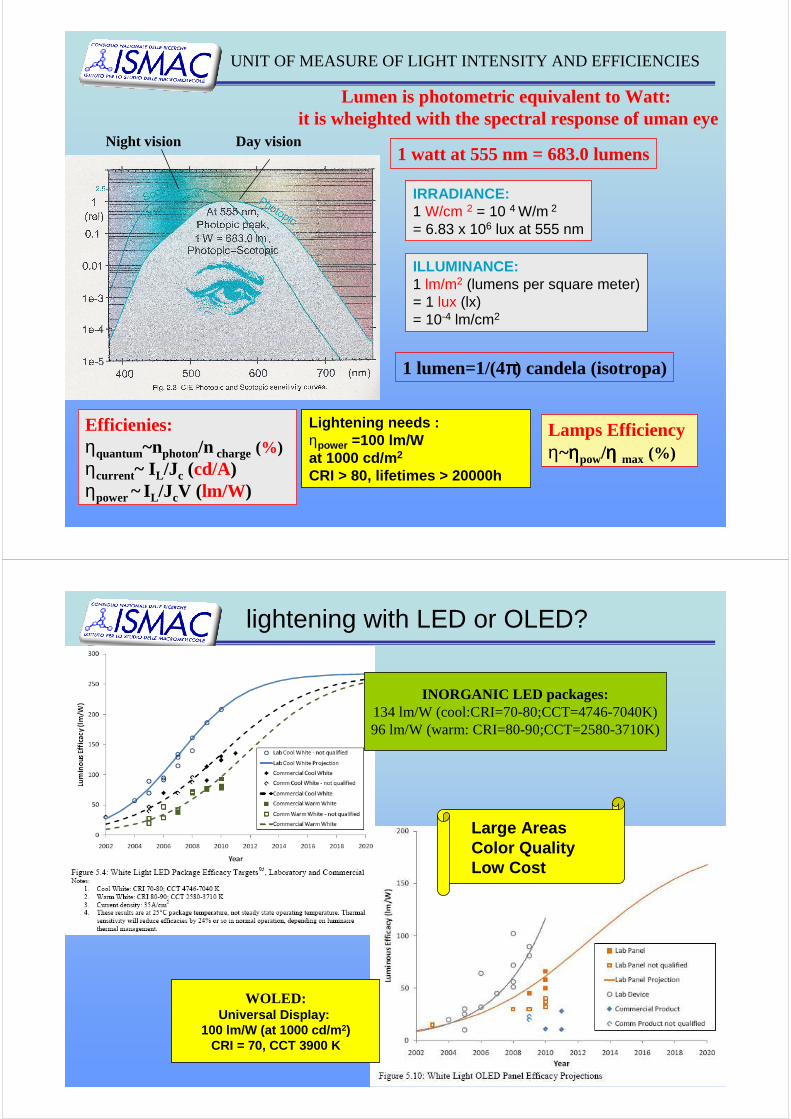
Lumen is photometric equivalent to Watt:it is wheighted with the spectral response of uman eye
1 watt at 555 nm = 683.0 lumensNight vision Day vision
ILLUMINANCE:1 lm/m2 (lumens per square meter)= 1 lux (lx)= 10-4 lm/cm2
IRRADIANCE:1 W/cm 2 = 10 4 W/m 2
= 6.83 x 10⁶ lux at 555 nm
Efficienies:ηquantum~nphoton/n charge (%)ηcurrent~ IL/Jc (cd/A)ηpower ~ IL/JcV (lm/W)
1 lumen=1/(4ππππ) candela (isotropa)
Lightening needs :ηpower =100 lm/W at 1000 cd/m 2
CRI > 80, lifetimes > 20000h
Lamps Efficiencyη~ηηηηpow/ηηηη max (%)
UNIT OF MEASURE OF LIGHT INTENSITY AND EFFICIENCIES
lightening with LED or OLED?
WOLED:Universal Display:
100 lm/W (at 1000 cd/m 2)CRI = 70, CCT 3900 K
INORGANIC LED packages:134 lm/W (cool:CRI=70-80;CCT=4746-7040K)96 lm/W (warm: CRI=80-90;CCT=2580-3710K)
Large AreasColor QualityLow Cost
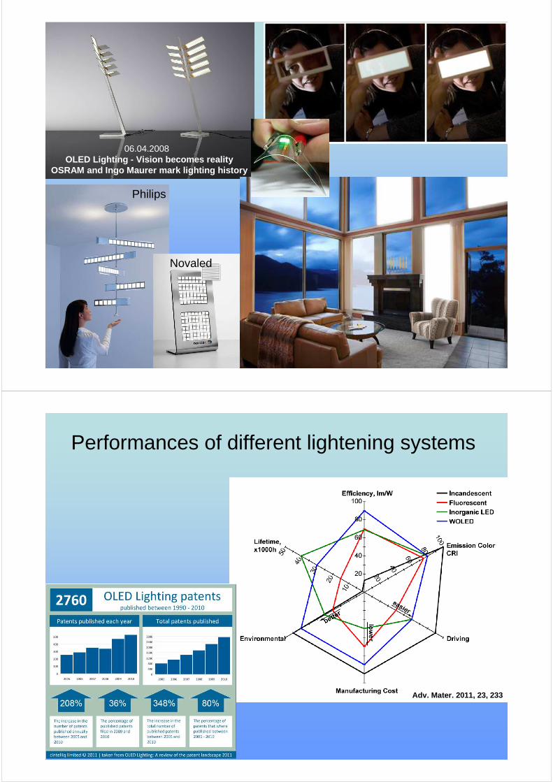
06.04.2008 OLED Lighting - Vision becomes reality
OSRAM and Ingo Maurer mark lighting history
Philips
Novaled
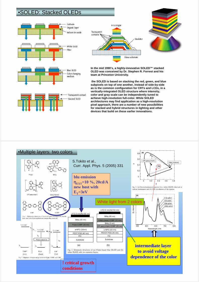
Performances of different lightening systems
Adv. Mater. 2011, 23, 233

Companies investing in WOLEDS
Strategies for WOLED
• Stacked devices (two or more) each of one emits a differentcolor (only molecules)
• Device with multiple layers (only molecules)
• LED with single layer emitting white light (molecules and/or polymers)– Mix of 2 or 3 materials– One material : emission from monomer + excimer– One material: copolymer
White light can be obtained as sum of two complementary colorsor three primary colors
Low cost deposition techniques (deposition from solution)
High cost deposition techniques (evaporation in vacuum)
•SOLED: Stacked OLEDs
In the mid 1990’s, a highly-innovative SOLED™ stackedOLED was conceived by Dr. Stephen R. Forrest and histeam at Princeton University.
the SOLED is based on stacking the red, green, and blu e subpixels on top of one another, instead of side-by-s ideas is the common configuration for CRTs and LCDs, in a vertically-integrated OLED structure where intensity, color and gray scale can be independently tuned toachieve high-resolution full-color. While SOLED architectures may find application as a high-resolutionpixel approach, there are a number of new possibiliti esfor stacked and hybrid structures in lighting and otherdevices that build on these earlier innovations.
S.Tokito et al.,Curr. Appl. Phys. 5 (2005) 331
blu emissionηηηηEXT=10 %, 20cd/Anew host withET=3eV
intermediate layerto avoid voltage
dependence of the color! critical growthconditions
White light from 2 colors
•Multiple layers: two colors

Management of singlet and triplet excitons for efficien twhite organic light-emitting devicesStephen R. Forrest et al. Nature, 440, 908 (2006)
ηηηηp = 37.6 lm/W, ηηηηext = 18.7 % At a practical surface luminance of 500 cd/m 2, ηηηηp = 23.8 lm/W, approximately 50% greaterof common incandescent lighting.
Different harvesting of singlet and triplets gives high CRI = 85 at all current densities studied
Triplet diffusion length L D = (460 ± 30) Å, (75 ± 5)% of the phosphoresce results from Tripletexciton diffusion from the adjacent EML interfaces
CRI = 85, CIE (0.40;0.40)reduced sensitivity of ηηηηextto current densityabsence of triplet–tripletannihilation suggests that the highest density of triplet excitonsis at the interfaces in the fluorescent doped regions
Low doping 5%
Layer undopedX>R Foester
•Multiple layers: three colors
Triplet-Harvesting ConceptK. Leo et al. Adv. Funct. Mater. 19, 1319 (2009);Nature 459,234 (2009); Adv. Mater. 19, 3672 (2007).
•Multiple layer: three colors
Fluorescent blue emitterwith hight T level
Phosphorescent orangeemitter
Phosphorescent green emitter
←e-
h+→
←
T
S T
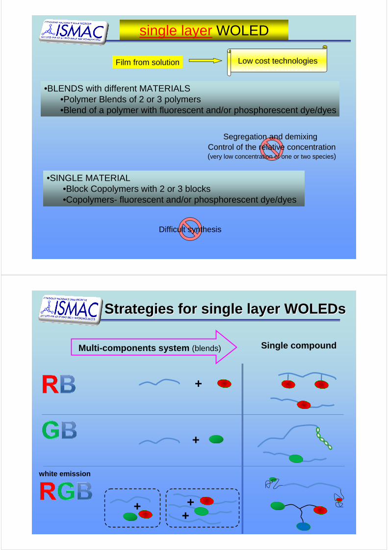
single layer WOLED
•BLENDS with different MATERIALS•Polymer Blends of 2 or 3 polymers•Blend of a polymer with fluorescent and/or phosphorescent dye/dyes
Segregation and demixingControl of the relative concentration(very low concentration of one or two species)
•SINGLE MATERIAL•Block Copolymers with 2 or 3 blocks•Copolymers- fluorescent and/or phosphorescent dye/dyes
Difficult synthesis
Film from solution Low cost technologies
Strategies for single layer Strategies for single layer WOLEDsWOLEDs
Multi-components system (blends) Single compound
+
+
++
+
white emission

0
1
300 400 500 600 700 800Wavelength (nm)
PL
ELelectroplexPVK:FSB
electroplexPVK:PBD
electromerPVK
ηELEXT = 0.52 %
ITO/PEDOT:PSS/blend/Ca/Al
CIE (0.22;0.23)
PVK : FSB
h-transp fluorescentdye
N
FF
F
FF
PBD :
e-transp
N
O
N
Broadening of the emission zone from blue towards white
Appl. Phys. Lett. 87, 171910 (2005)
Blend one polymer with two molecules
0
500
1000
1500
2000
400 450 500 550 600 650 700 750
PL of Tb(hfa)4P(ph)
4 in CH
2Cl
2
PL
PL
(a.u
.)
wavelength (nm)
5D4
7F6
5D4
5D4
5D4
5D4
7F5
7F4
7F3
7F2
0
5000
1 104
1,5 104
2 104
2,5 104
450 500 550 600 650 700 750
PL of Eu(tta)4N(et)
4 in CH
2Cl
2
PL
PL
(a.u
.)
wavelength (nm)
5D0
5D0
5D0
5D0
7F1
7F2
7F3
7F4
NCH
CH2
n
300 400 500 600 700
PL
inte
nsity
(a.
u.)
Wavelength (nm)
PVK
350 400 450 500 550 600
PL
inte
nsity
(a.
u.)
Wavelength (nm)
PBD
O
NNt-Bu
Blend one polymer with two Org-Ln
Phys. Chem. Chem. Phys., 2009, 11, 10152
9,5 V 18 V
low Vhigh V
x=0,33y=0,45
EL 14V
0
0,2
0,4
0,6
0,8
1
350 400 450 500 550 600 650 700 750
EL
inte
nsity
(a.
u.)
wavelength (nm)
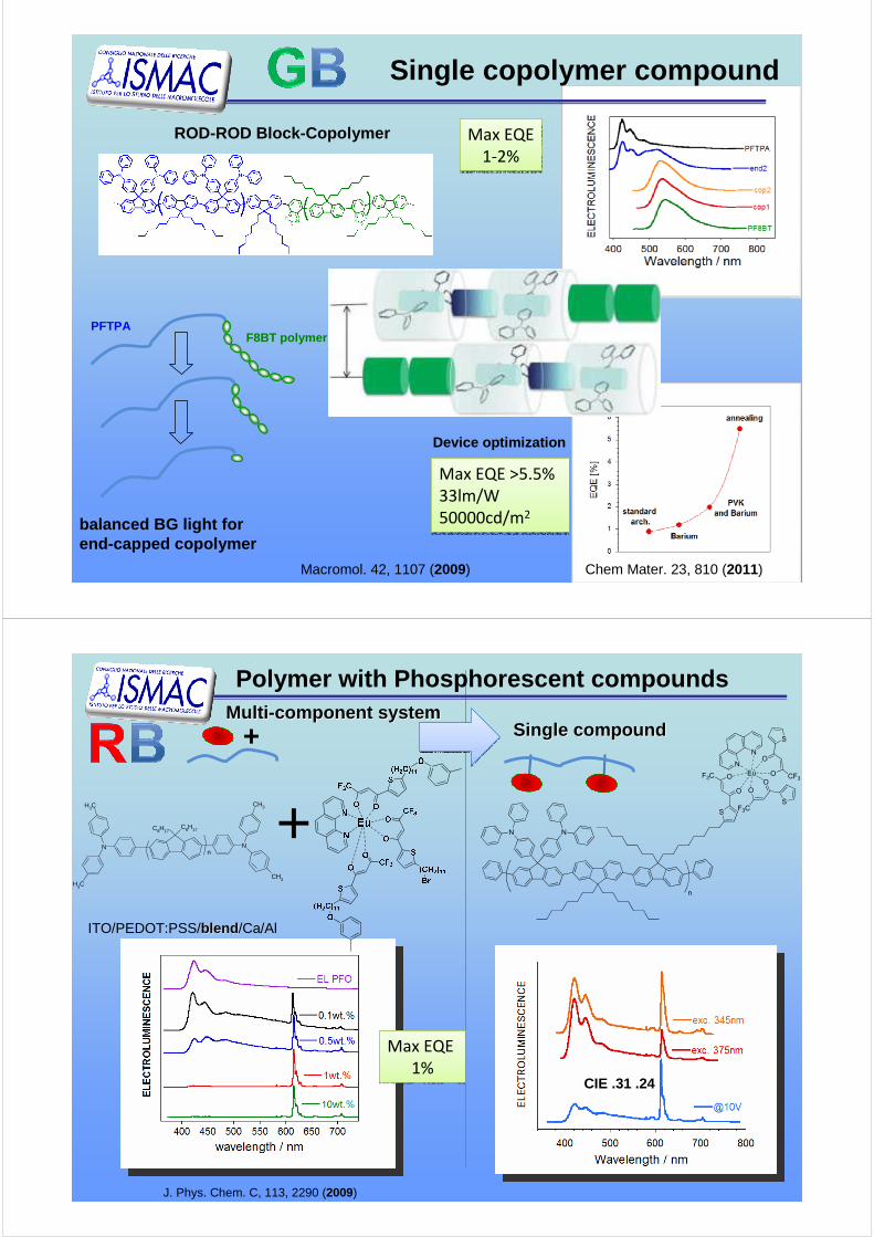
Single copolymer compound
PFTPA
balanced BG light forend-capped copolymer
F8BT polymer
ROD-ROD Block-Copolymer Max EQE
1-2%
Max EQE
1-2%
Macromol. 42, 1107 (2009)
Device optimization
Max EQE >5.5%
33lm/W
50000cd/m2
Max EQE >5.5%
33lm/W
50000cd/m2
Chem Mater. 23, 810 (2011)
NNn
C8H17C8H17
CH3
CH3
CH3
CH3
+
+MultiMulti --componentcomponent systemsystem
Single Single compoundcompound
CIE .31 .24
J. Phys. Chem. C, 113, 2290 (2009)
Max EQE
1%
Max EQE
1%
ITO/PEDOT:PSS/blendblend /Ca/Al
N N
S
O
n
OF3CEu
N
N
S
O
O
F3C
S
O
OCF3
Polymer with Phosphorescent compounds
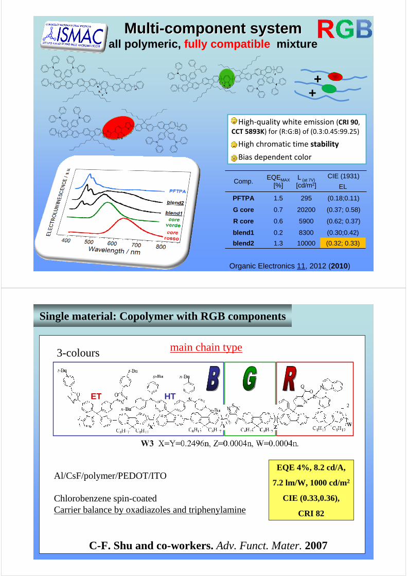
MultiMulti --componentcomponent systemsystemall polymeric, fully compatible mixture
++
Comp.EQEMAX
[%]L (at 7V)[cd/m2]
CIE (1931)
EL
PFTPA 1.5 295 (0.18;0.11)
G core 0.7 20200 (0.37; 0.58)
R core 0.6 5900 (0.62; 0.37)
blend1 0.2 8300 (0.30;0.42)
blend2 1.3 10000 (0.32; 0.33)
Organic Electronics 11, 2012 (2010)
• High-quality white emission (CRI 90,
CCT 5893K) for (R:G:B) of (0.3:0.45:99.25)
• High chromatic time stability
• Bias dependent color
N N
N
SN
NN
SS
n
n
Single material: Copolymer with RGB components
C-F. Shu and co-workers.Adv. Funct. Mater. 2007
Al/CsF/polymer/PEDOT/ITO
Chlorobenzene spin-coatedCarrier balance by oxadiazoles and triphenylamine
main chain type3-colours
EQE 4%, 8.2 cd/A,
7.2 lm/W, 1000 cd/m2
CIE (0.33,0.36),
CRI 82
ET HT

Chem.Phys.Chem. 11, 683 (2010)
excimerelectromer
systems containing pyrene units (excitonand excimers) as energy donors and a styrylpyridiniumderivative as energyacceptor
Towards single Towards single dendronicdendronic materialmaterial
Dendronicantennae
White lightHost PVK matrix for electroluminescence
(0.35; 0.40)
Stefano CicchiUniv. Firenze
Self-organized micro- nano- structuresfor OLEDs applications
Device reduced sizes improve integration capabiliy and increasesnumber of functions/volume
Organic/Organic or Organic/Inorganic nanostructures can improve OLED’s performances by:• separation of radiative recombination from charge transport, • ordered micro-pattern useful for pixeling
The auto-assembly ability of organics allows to easilyobtain ordered micro and nano-structures for a device
The auto-organization in hybrid nanostructures improvesthe stability of organic materials
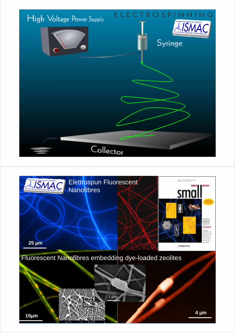
4 µµµµm
25 µµµµm
10µµµµm
Fluorescent Nanofibres embedding dye-loaded zeolites
Elettrospun FluorescentNanofibres
1 µm
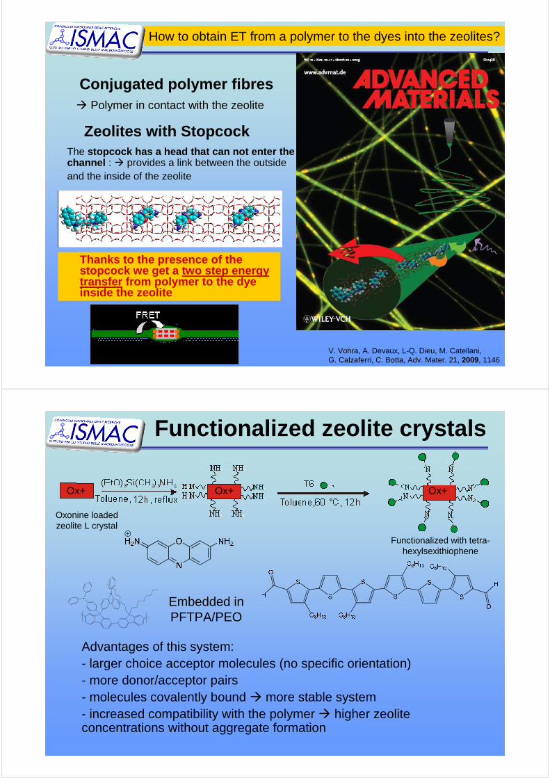
Zeolites with StopcockThe stopcock has a head that can not enter the channel : � provides a link between the outside and the inside of the zeolite
Conjugated polymer fibres� Polymer in contact with the zeolite
How to obtain ET from a polymer to the dyes into the zeolites?
Thanks to the presence of the stopcock we get a two step energytransfer from polymer to the dyeinside the zeolite
V. Vohra, A. Devaux, L-Q. Dieu, M. Catellani, G. Calzaferri, C. Botta, Adv. Mater. 21, 2009, 1146
Functionalized zeolite crystals
Embedded in PFTPA/PEO
Advantages of this system: - larger choice acceptor molecules (no specific orientation)- more donor/acceptor pairs - molecules covalently bound � more stable system- increased compatibility with the polymer � higher zeoliteconcentrations without aggregate formation
Oxonine loadedzeolite L crystal
Ox+ Ox+ Ox+
Functionalized with tetra-hexylsexithiophene
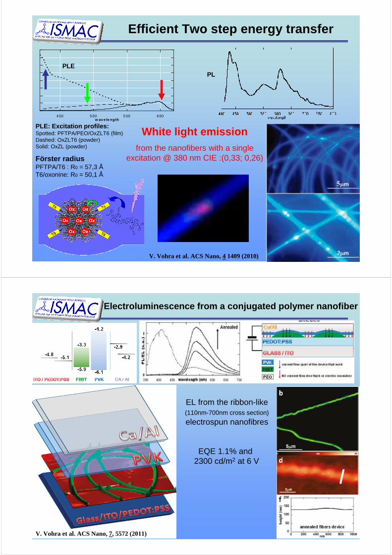
Efficient Two step energy transfer
Förster radiusPFTPA/T6 : R0 = 57,3 ÅT6/oxonine: R0 = 50,1 Å
4 50 5 00 5 50 6 00w av e le ngth
PLE: Excitation profiles:Spotted: PFTPA/PEO/OxZLT6 (film)Dashed: OxZLT6 (powder)Solid: OxZL (powder)
PLPLE
V. Vohra et al. ACS Nano, 41409 (2010)
White light emissionfrom the nanofibers with a single
excitation @ 380 nm CIE :(0,33; 0,26)
Electroluminescence from a conjugated polymer nanofiber
V. Vohra et al. ACS Nano, 7, 5572 (2011)
EQE 1.1% and 2300 cd/m2 at 6 V
EL from the ribbon-like(110nm-700nm cross section)
electrospun nanofibres

Acknowledgements
• Varun Vohra, Dr. Sami Yunus, Dr. Fabrice Spano, Dr. Marinella Catellani, Dr. Umberto Giovanella, Dr. Alberto Bolognesi, Dr. Williamo Porzio, Dr. Silvia Destri, Dr M Pasini, Dr. Guido Scavia(ISMac-CNR, Milano)
• Prof. Gion Calzaferri, Dr. André Devaux(University of Bern)
• Prof. Luisa De Cola, Fabio Cucinotta (Univ. of Muenster)
• S. Cicchi (UNIFI and INSTM), M. Melucci (ISOF), G. Farinola(UNIBA), D. Roberto (UNIMI), G. Zotti, B. Vercelli (IENI-CNR)
•the European Commission through the Human Potential Program (Marie-Curie RTN “Nanochannel” and 'Nanomatch' Contracts)•CARIPLO Foundation – SOLCO
WOLEDs: MIUR -FIRB RBNE03S7XZ SINERGY -FIRB-RBIP06JWBH NODIS -FIRB-RBIP0642YL LUCI -PRIN 2007PBWN44
CARIPLO Foundation –WOLED
Regione Lombardia - IndoLED