Embed Size (px)
Citation preview

Original BMW Accessories.Installation Instructions.
Universal BMW Bluetooth Hands-Free Kit RetrofitBMW 5 Series Saloon (E 60)These installation instructions are only valid for cars with SA 473 (front armrest)
Retrofit kit no.: 84 64 0 307 681 Universal BMW Bluetooth hands-free kit retrofit kit 61 12 0 442 293 Adapter cable for telephone control unit 61 12 6 962 814 Aerial cable
Installation timeThe installation time is approx. 5.5 to 6.0 hours. This may vary depending on the condition of the car and the equipment in it. The installation time will decrease by approx. 0.5 hours for cars with a ULF control unit already fitted.For cars without SA 606, SA 609 or SA 654, the installation time will increase by approx. 1.0 hour for the installation of the roof aerial.
The vehicle must be updated to the latest I-level status by flashing before installing the retrofit. Differing programming times may be necessary depending on the production age of the vehicle and on work previously performed on the vehicle.
The installation time given does not include time needed for programming/encoding.
The total costs for the programming time should be taken into account when calculating retrofitting costs (reimbursement through warranty is not permissible).
Important information These installation instructions are primarily designed for use within the BMW dealership organisation and by authorised BMW service companies.
In any event, the target group for these installation instructions is specialist personnel trained on BMW cars with the appropriate specialist knowledge.
All work must be completed using the latest BMW repair manuals, circuit diagrams, servicing manuals and work instructions, in a rational order, using the prescribed tools (special tools) and observing current health and safety regulations.
If you experience installation or function problems, limit troubleshooting to approx. 0.5 hours for mechanical or 1.0 hour for electrical work. In order to reduce costs and avoid any additional expense, send a query immediately to the Technical Parts Support via the Aftersales Assistance Portal (ASAP).Specify the following information:- Chassis number- Part number of the retrofit kit- A precise description of the problem- Work steps already carried out
Do not archive the hard copy of these installation instructions since daily updates are made by ASAP!
© BMW AG, Munich 01 29 0 392 759 9/2007 (Z/Z) 1

PictogramsDenotes instructions that draw your attention to special features.
Denotes the end of the instruction or other text.
Installation informationWhen routing fibre optic cables, make sure the bending radius is no less than 25 mm. Refer to the instructions for handling fibre optic cables acc. to TIS RA 61 00 ....
Ensure that the cables and/or lines are not kinked or damaged as you install them in the car. The costs thereby incurred will not be reimbursed by BMW AG.
Additional cables/lines that you install must be secured with cable ties.
If the specified PIN chambers are occupied, bridges, double crimps or twin-lead terminals must be used.
All pictures show LHD cars; proceed accordingly on RHD cars.
After the installation work the retrofit must be programmed / coded using SSS (software service station) via the CIP path.
In the following equipment variants, the ULF control unit is already fitted, connected to a large extent and doesn’t need replacing:
- Cars with SA 620 without SA 609
- Cars with SA 6FL
Ordering instructionsThe following parts are not included in the retrofit kit and must be ordered separately (see EPC for part number and details):
- Snap-in adapter
- ULF control unit K
- Centre armrest cover O
- Headlining trim S or T (cars without SA 620 only)
- Adapter cable (telephone control unit) V with socket casing W
- Aerial cable X
List of special equipmentThe following special equipment must be taken into consideration when installing the retrofit kit:
SA 403 Glass roofSA 493 Front armrestSA 606 Radio navigation systemSA 609 Professional navigation systemSA 620 Voice input systemSA 654 DAB tunerSA 6FF DVD system in rearSA 6FL USB/audio interface
Special tools required00 9 310, Installation wedges65 2 010 Cutter set for roof aerial (cars without SA 606, SA 609 or SA 654 only)
© BMW AG, Munich 01 29 0 392 759 9/2007 (Z/Z) 2

Table of contents
Section Page
1. Parts list . . . . . . . . . . . . . . . . . . . . . . . . . . . . . . . . . . . . . . . . . . . . . . . . . . . . . . . . . . . . . . . . . . . . . . . . . . . . . . . . . . . . . 4
2. Preparatory work . . . . . . . . . . . . . . . . . . . . . . . . . . . . . . . . . . . . . . . . . . . . . . . . . . . . . . . . . . . . . . . . . . . . . . . . . . . . . 6
3. Connection diagram . . . . . . . . . . . . . . . . . . . . . . . . . . . . . . . . . . . . . . . . . . . . . . . . . . . . . . . . . . . . . . . . . . . . . . . . . . 7
4. Extra connection diagram (cars with ULF control unit already fitted only) . . . . . . . . . . . . . . . . . . . . . . . . . . . . 10
5. Installation and cabling diagram . . . . . . . . . . . . . . . . . . . . . . . . . . . . . . . . . . . . . . . . . . . . . . . . . . . . . . . . . . . . . . . . 11
6. To install and connect the ULF control unit (cars without ULF control unit already fitted only) . . . . . . . . . 12
7. To connect the ULF control unit (cars with ULF control unit already fitted only) . . . . . . . . . . . . . . . . . . . . . . 13
8. To install the roof aerial (cars without SA 606, SA 609 or SA 654 only) . . . . . . . . . . . . . . . . . . . . . . . . . . . . . 15
9. To install and connect the cable kit . . . . . . . . . . . . . . . . . . . . . . . . . . . . . . . . . . . . . . . . . . . . . . . . . . . . . . . . . . . . . 16
10. To connect the fibre optic cable of the wiring harness (cars without ULF control unit already fitted only) . . . . . . . . . . . . . . . . . . . . . . . . . . . . . . . . . . . . . . . . . . . . . . . . . 19
11. To install and connect the Bluetooth aerial and eject box . . . . . . . . . . . . . . . . . . . . . . . . . . . . . . . . . . . . . . . . . . 21
12. To install and connect the hands-free microphone . . . . . . . . . . . . . . . . . . . . . . . . . . . . . . . . . . . . . . . . . . . . . . . 23
13. Concluding work and coding . . . . . . . . . . . . . . . . . . . . . . . . . . . . . . . . . . . . . . . . . . . . . . . . . . . . . . . . . . . . . . . . . . 25
14. Pairing the mobile phone . . . . . . . . . . . . . . . . . . . . . . . . . . . . . . . . . . . . . . . . . . . . . . . . . . . . . . . . . . . . . . . . . . . . . . 26
15. Circuit diagram (cars without ULF control unit already fitted only) . . . . . . . . . . . . . . . . . . . . . . . . . . . . . . . . . . 27
16. Circuit diagram (cars with ULF control unit already fitted only) . . . . . . . . . . . . . . . . . . . . . . . . . . . . . . . . . . . . . 29
17. Cable colours . . . . . . . . . . . . . . . . . . . . . . . . . . . . . . . . . . . . . . . . . . . . . . . . . . . . . . . . . . . . . . . . . . . . . . . . . . . . . . . . 31
© BMW AG, Munich 01 29 0 392 759 9/2007 (Z/Z) 3

1. Parts list
Legend
A Wiring harness
AA ABS/DSC wiring harness (not required)
B Roof aerial (cars without SA 606, SA 609 or SA 654 only)
C Hands-free microphone trim (cars without SA 620 only)
D Eject box
E Short circuit casing (cars without ULF control unit already fitted only)
F Self-tapping screw (cars without SA 606, SA 609 or SA 654 only)
G Cable tie
H Telephone mounting
I Bluetooth aerial
J ULF holder (cars without ULF control unit already fitted only)
A B C D E
F G H I J
AA
060 0404 Z
© BMW AG, Munich 01 29 0 392 759 9/2007 (Z/Z) 4
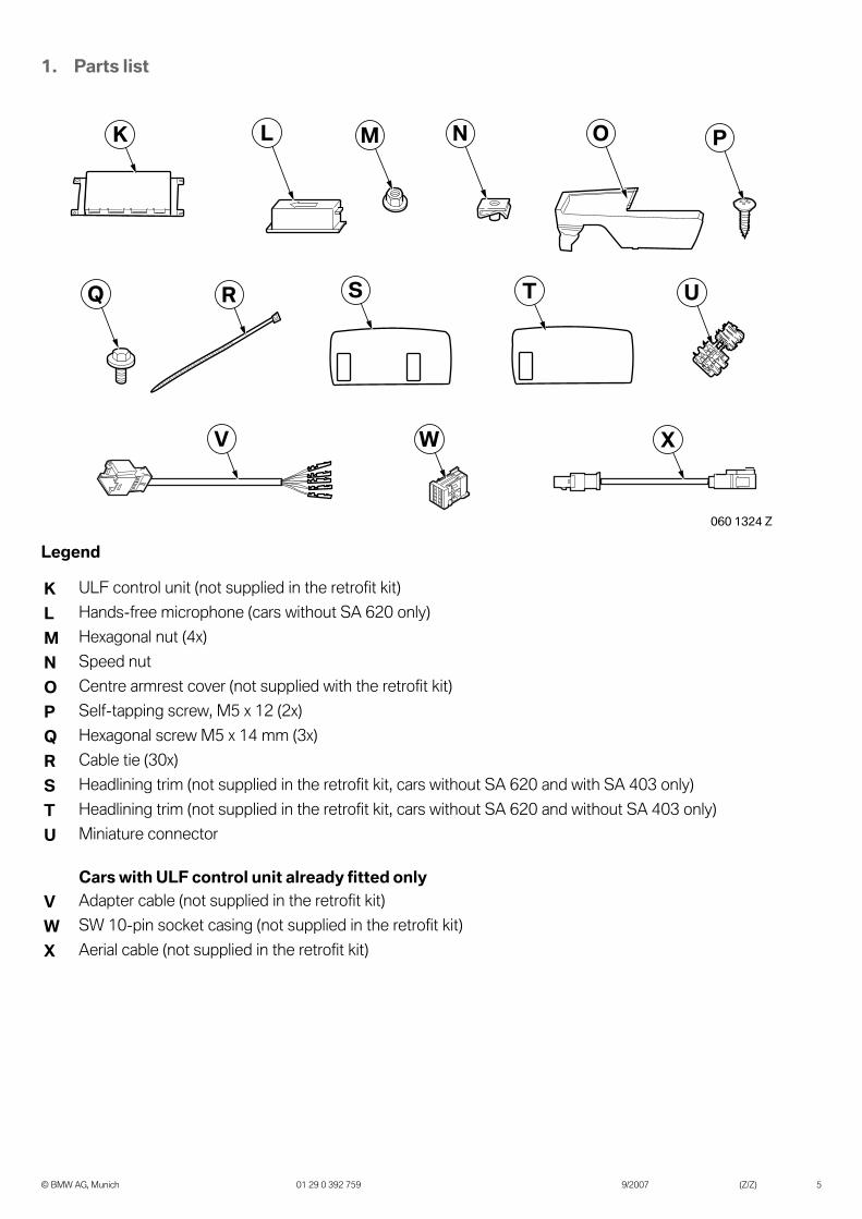
1. Parts list
Legend
K ULF control unit (not supplied in the retrofit kit)
L Hands-free microphone (cars without SA 620 only)
M Hexagonal nut (4x)
N Speed nut
O Centre armrest cover (not supplied with the retrofit kit)
P Self-tapping screw, M5 x 12 (2x)
Q Hexagonal screw M5 x 14 mm (3x)
R Cable tie (30x)
S Headlining trim (not supplied in the retrofit kit, cars without SA 620 and with SA 403 only)
T Headlining trim (not supplied in the retrofit kit, cars without SA 620 and without SA 403 only)
U Miniature connector
Cars with ULF control unit already fitted onlyV Adapter cable (not supplied in the retrofit kit)
W SW 10-pin socket casing (not supplied in the retrofit kit)
X Aerial cable (not supplied in the retrofit kit)
SQ R
LK M N O P
T U
WV X
060 1324 Z
© BMW AG, Munich 01 29 0 392 759 9/2007 (Z/Z) 5

2. Preparatory work
TIS no.Conduct a brief test ---
Disconnect negative pole of battery 12 00 ...
The following components must be removed first of allBoot side trim, left and right 51 47 ...
Boot floor trim 51 47 210
Rear closing panel cover 51 46 050
ULF control unit in spare wheel trough (cars with ULF control unit already fitted only)
84 21 542
Rear seat and backrest side section, left, pull down the backrest 52 24 010
Headlining trim for roof aerial ---
Roof pillar trim, rear left 51 43 251
Door sill strips left, front and rear 51 47 ...
Pedal trim 51 45 185
Trim at the bottom left of the door pillar 51 43 150
Lower the A pillar trim on the left 51 43 201
Front headlining trim 51 44 ...
Driver's seat 52 14 ...
Trim for oddments box 51 16 211
M-ASK or CCC (cars without ULF control unit already fitted only)
65 83 010
© BMW AG, Munich 01 29 0 392 759 9/2007 (Z/Z) 6

© BMW AG, Munich 01 29 0 392 759 9/2007 (Z/Z) 7
3. Connection diagram
Item Designation Signal Cable colour / Cross-section
Connection site in the car Abbreviation / Slot
A Wiring harness --- --- --- ---
A1 SW 3-pin socket casing --- --- For optional aerial booster X1765
A2 SW Fakra plug casing --- --- On branch A3 X13323
A3 Fakra socket casing, SW --- --- On branch A2 X13337
A4 SW Fakra plug casing --- --- Tie back, not required ---
A5 Fakra socket casing, WS
--- ---
Cars without ULF control unit already fitted onlyTo ULF control unit KCars with ULF control unit already fitted onlyTo aerial cable X, branch X1
X11575
---
A6 Fakra socket casing, SW --- --- Tie back, not required ---
A7 Fakra socket casing, VI --- --- Tie back, not required ---
A8 Fakra socket casing, BL --- --- Tie back, not required ---
A9 Fakra socket casing, VI --- --- Tie back, not required ---
A10 Fakra socket casing, BO/VI --- --- To roof aerial B X13363
A11 Fakra socket casing, BL --- --- Tie back, not required ---
A12 SW 3-pin socket casing Mic I --- To hands-free microphone L X13293
A13 6-pin WS socket casing --- --- Tie back, not required ---
A14 Joint connector contact DFAVL GE/RT0.35 mm2
Insulate and tie back---
A15 Joint connector contact DFAVR GE/WS0.35 mm2
Insulate and tie back---
A16 Joint connector contact 58G GR/RT0.35 mm2
Insulate and tie back---
A17 Socket contact TEL Crash SW/RT0.35 mm2
Insulate and tie back---
SA 644 SA 638
A29
A31A27
A26
A25 A23
A22
A28A32
A24 A20A19
A18
A16
A17
A33
A1
A2 A5 A10
A6
A7A12A13
A14 A15
A3 A9
A30
A
A4
A8
A11
060 0397 Z

3. Connection diagram
Item Designation Signal Cable colour / Cross-section
Connection site in the car Abbreviation / Slot
A18 Fibre optic cable connector MOST GN Cars without ULF control unit already fitted onlyTo disconnected fibre optic cable on M-ASK or CCC
Cars with ULF control unit already fitted onlyTie back, not required
X13815PIN 2
---
A19 Fibre optic cable MOST GN Cars without ULF control unit already fitted onlyTo the MOST of the fibre optic cable casing to M-ASK or CCCCars with ULF control unit already fitted onlyTie back, not required
X13815PIN 2
---
A20 12-pin socket casing, SW Tel NF+/- --- Tie back, not required ---
A22 Socket contact TEL Wakeup
GE0.35 mm2
Insulate and tie back---
A23 VI 3-pin socket casing --- --- Tie back, not required ---
A24 SW 18-pin socket casing --- --- To eject box D X4545
A25 SW Fakra plug casing --- --- To eject box D X13514
A26 Fakra socket casing, GN Ant BT --- To Bluetooth aerial I X11574
A27 Cable eyelet 31 BR0.35 mm2
Insulate and tie back---
SA 644 SA 638
A29
A31A27
A26
A25 A23
A22
A28A32
A24 A20A19
A18
A16
A17
A33
A1
A2 A5 A10
A6
A7A12A13
A14 A15
A3 A9
A30
A
A4
A8
A11
060 0397 Z
© BMW AG, Munich 01 29 0 392 759 9/2007 (Z/Z) 8

3. Connection diagram
Item Designation Signal Cable colour / Cross-section
Connection site in the car Abbreviation / Slot
A28 2-pin SW fibre optic cable casing MOST
---
Cars without ULF control unit already fitted onlyTo ULF control unit KCars with ULF control unit already fitted onlyTie back, not required
X10634
---
A29 54-pin WS socket casing
--- ---
Cars without ULF control unit already fitted onlyTo ULF control unit KCars with ULF control unit already fitted onlyConnect cable in socket casing W
X695
---
A30 SW 3-pin socket casing --- --- Tie back, not required ---
A31 Cable eyelet 31 BR To the earth post in the rear left wheel arch X13793
A32 Socket contact 15 GN/BR0.75 mm2
Insulate and tie back---
A33 Socket contact 30 RT/BR0.75 mm2
Cars built before 09/05 onlyOn fuse holder at the rear rightCars built after 09/05 onlyOn fuse holder at the rear right
X11015PIN 3X11012PIN 39
SA 644 SA 638
A29
A31A27
A26
A25 A23
A22
A28A32
A24 A20A19
A18
A16
A17
A33
A1
A2 A5 A10
A6
A7A12A13
A14 A15
A3 A9
A30
A
A4
A8
A11
060 0397 Z
© BMW AG, Munich 01 29 0 392 759 9/2007 (Z/Z) 9

© BMW AG, Munich 01 29 0 392 759 9/2007 (Z/Z) 10
4. Extra connection diagram (cars with ULF control unit already fitted only)
Item Designation Signal Cable colour / Cross-section
Connection site in the car Abbreviation / Slot
V Adapter cable --- --- --- ---
V1 SW 10-pin plug casing --- --- To socket casing W ---
V2 Socket contact Mic + SW0.35 mm2
To ULF control unit in spare wheel trough, BL 54-pin socket casing
X14133PIN 1
V3 Socket contact Mic - GE0.35 mm2
To ULF control unit in spare wheel trough, BL 54-pin socket casing
X14133PIN 19
V4 Socket contact Shield TR0.35 mm2
To ULF control unit in spare wheel trough, BL 54-pin socket casing
X14133PIN 21
V5 Socket contact Cradle On BR/WS0.35 mm2
To ULF control unit in spare wheel trough, BL 54-pin socket casing
X14133PIN 11
V6 Socket contact Cradle Key+
GN0.35 mm2
To ULF control unit in spare wheel trough, BL 54-pin socket casing
X14133PIN 32
W SW 10-pin socket casing--- ---
Connect disconnected cable of branch A29 ---
X Aerial cable --- --- --- ---
X1 Fakra plug casing, GN --- --- To branch A5 X11575
X2 Fakra socket casing, GN --- --- To ULF control unit in spare wheel trough X11575
W V
X
V5V6
X1 X2
V1
V2V3
V4
060 1325 Z

5. Installation and cabling diagram
Legend
A Wiring harness
B Roof aerial
D Eject box
I Bluetooth aerial
K ULF control unit (cars without ULF control unit already fitted only)
L Hands-free microphone
V Adapter cable (cars with ULF control unit already fitted only)
X Aerial cable (cars with ULF control unit already fitted only)
1 M-ASK or CCC (cars without ULF control unit already fitted only)
2 Fuse holder at the rear right
3 Earth post X13793 on the rear left wheel arch
4 ULF control unit already fitted
060 1326 Z
E65
DI1
3
2
KA
L B
VX4
© BMW AG, Munich 01 29 0 392 759 9/2007 (Z/Z) 11

© BMW AG, Munich 01 29 0 392 759 9/2007 (Z/Z) 12
6. To install and connect the ULF control unit (cars without ULF control unit already fitted only)
Place a speed nut N on the holder (1).
Secure the ULF holder J using hexagonal screws Q.
Connect the following branches to ULF control unit K:
- Branch A5, WS plug
- Branch A28, fibre optic cable casing
- Branch A29, white 54-pin plug
Tie back the following branches:
- Branch A6, SW plug
- Branch A7, VI plug
- Branch A8, VI plug
- Branch A30, SW 3-pin plug
Secure the ULF control unit K to the ULF holder J using hexagonal nuts M.
060 0071 Z
N1
060 0260 Z
J
K
A5
A28A29
A6-A8, A30
060 1292 Z
K M
M
J060 0348 Z

7. To connect the ULF control unit(cars with ULF control unit already fitted only)
Connect branch A5, WS plug, to aerial cable X.
Tie back the following branches:
- Branch A6, SW plug
- Branch A7, VI plug
- Branch A8, VI plug
- Branch A28, fibre optic cable casing
- Branch A30, SW 3-pin plug
Disconnect the following cables (1) from branch A29, white 54-pin, and connect socket casing W:
- BR/WS cable from PIN 19 to PIN 1
- WS cable from PIN 1 to PIN 2
- Screen cable from PIN 21 to PIN 3
- SW cable from PIN 32 to PIN 4
- BR/WS cable from PIN 11 to PIN 5
Disconnect, individually insulate and tie back all remaining cables from A29.
Connect socket casing W to adapter cable V.
Route adapter cable V and aerial cable X along the wiring harness as follows:
- to rear bulkhead
- into the control unit holder
- to the installation site of the ULF control unit (1)
A5
X
060 1327 Z
A6-A8, A28, A30
1
VA29
W
060 1328 Z
X
1 V
060 1329 Z
© BMW AG, Munich 01 29 0 392 759 9/2007 (Z/Z) 13
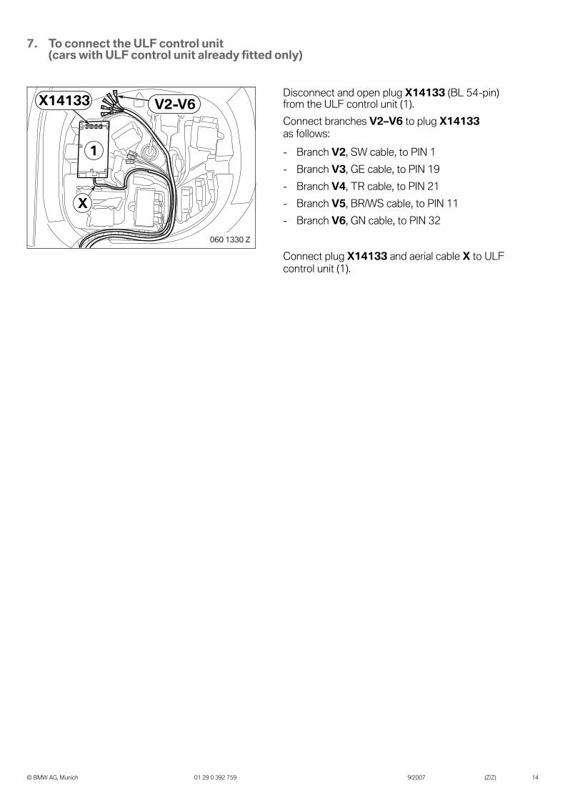
7. To connect the ULF control unit(cars with ULF control unit already fitted only)
Disconnect and open plug X14133 (BL 54-pin) from the ULF control unit (1).
Connect branches V2–V6 to plug X14133 as follows:
- Branch V2, SW cable, to PIN 1
- Branch V3, GE cable, to PIN 19
- Branch V4, TR cable, to PIN 21
- Branch V5, BR/WS cable, to PIN 11
- Branch V6, GN cable, to PIN 32
Connect plug X14133 and aerial cable X to ULF control unit (1).
1
X14133 V2-V6
X
060 1330 Z
© BMW AG, Munich 01 29 0 392 759 9/2007 (Z/Z) 14

8. To install the roof aerial (cars without SA 606, SA 609 or SA 654 only)
Mask the area around the roof aerial to prevent damaging the paintwork.
Carefully cut the empty casing (1) for the roof aerial off the rood with the special tool.
Clean the surfaces in the bonding areas on the empty casing (1) and roof.
Slide in the roof aerial B at the rear (1) and secure it at the front with a self-tapping screw F.
The bonding surfaces must be clean and free of grease. The temperature of the adhesive
must be at least 20 °C. The hardening time of the adhesive is at least 4 hours.
Apply a bead of adhesive (2) around 8 mm wide and 8 mm high to the empty casing (1).
Carefully place the empty casing (1) in its original position, press lightly and secure it with adhesive tape.
1
060 0310 Z
B
F1
��� ���� �
1
2060 0312 Z
© BMW AG, Munich 01 29 0 392 759 9/2007 (Z/Z) 15

9. To install and connect the cable kit
Connect branch A3 (aerial symbol) to branch A2 (SA 644).
Tie back branch A1 and branch A4 (SA 638), they are not required.
Connect branch A31 to earth post X13793, on the rear left wheel arch.
Route branches A32 and A33 along the closing panel to the right side of the boot and secure it using cable holders (1).
Route branches A32 and A33 to the fuse holder at the rear right and secure the wiring harness A to the vehicle wiring harness with cable ties R.
Insulate branch A32, GN/BR cable, and tie it back.
Cars built before 09/05 only
Disconnect and release plug X11015 from the fuse holder.
Connect branch A33, RT/BR cable, to PIN 3 of plug X11015.
Cars built after 09/05 only
Connect branch A33, RT/BR cable, to PIN 39 of plug X11012.
060 0332 Z
SA 64
4
A4
A3 A2
A1
SA 63
8
060 1295 Z
X13793
A31A32-A331
A32
X11015
A
A33
060 1289 Z
R
X11012
A33
A
060 1290 Z
© BMW AG, Munich 01 29 0 392 759 9/2007 (Z/Z) 16

9. To install and connect the cable kit
Route branch A10, BO/VI, and branch A11, BL, to the installation site of the roof aerial.
Insulate branch A27 and tie it back.
Route wiring harness A along the standard wiring harness to the door sill.
Route branches A10–A11 to the roof aerial (1).
Connect branch A10,VI, to connector X13363 on the roof aerial (1).
Tie back branch A11, BL.
Cars without ULF control unit already fitted only
Insulate and tie back the following branches to a suitable point:
- Branch A14, GE/RT cable
- Branch A15, GE/WS cable
- Branch A16, GR/RT cable
- Branch A17, SW/RT cable
- Branch A20, 12-pin SW socket casing
- Branch A22, GE cable
- Branch A23, 3-pin VI socket casing
Route wiring harness A along the standard wiring harness as follows:
- Branches A12–A13 to the left A pillar
- Branches A18–A19 to the centre console and then towards the M-ASK or CCC
- Branches A24–A26 to the centre console
060 1301 Z
A
A10-A11
A27
060 0386 Z
X13363
A10 A11
1
A
A24-A26
A12-A13
A18-A19
060 1296 Z
© BMW AG, Munich 01 29 0 392 759 9/2007 (Z/Z) 17

9. To install and connect the cable kit
Cars with ULF control unit already fitted only
Insulate and tie back the following branches to a suitable point:
- Branch A14, GE/RT cable
- Branch A15, GE/WS cable
- Branch A16, GR/RT cable
- Branch A17, SW/RT cable
- Branch A18, fibre optic cable connector
- Branch A19, fibre optic cable
- Branch A20, 12-pin SW socket casing
- Branch A22, GE cable
- Branch A23, 3-pin VI socket casing
Route wiring harness A along the standard wiring harness as follows:
- Branches A12–A13 to the left A pillar
- Branches A24–A26 to the centre console
All cars
Route branches A12–A13 to the left A pillar via the lowered headlining to the opening in the roof trim.
Secure wiring harness A to the left A pillar (1) using a cable tie G.
Ensure that wiring harness A is routed and secured behind the head airbag.
A
A24-A26
A12-A13
060 1297 Z
060 0256 Z
A12
A13
A
G1
060 0335 Z
© BMW AG, Munich 01 29 0 392 759 9/2007 (Z/Z) 18

10. To connect the fibre optic cable of the wiring harness (cars without ULF control unit already fitted only)
In cars with the ULF control unit already fitted, the fibre optic cables are already fitted in the car and connected.
Route branches A18–A19 to the M-ASK or CCC.
Unclip fibre optic cable casing X13815 fromplug X13812.
Disconnect the outgoing fibre optic cable from fibre optic cable casing X13815 PIN 2 and connect branch A19.
Clip fibre optic cable casing X13815 into plug X13812 and connect it to the M-ASK or CCC.
Release the fibre optic cable connector (1) of branch A18.
Connect the fibre optic cable (2) you previously disconnected.
X13812
X13815
060 1291 Z
A19
A181
2
X13815A19060 0248 Z
2
A18
1
060 1298 Z
© BMW AG, Munich 01 29 0 392 759 9/2007 (Z/Z) 19
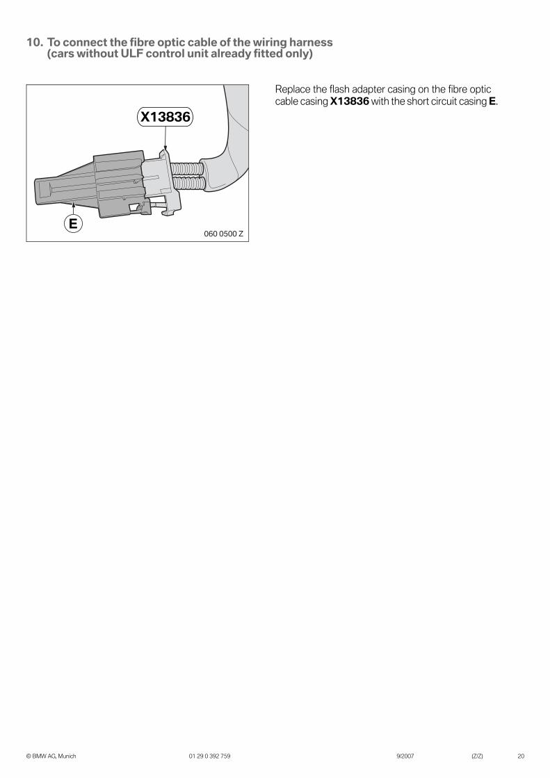
10. To connect the fibre optic cable of the wiring harness (cars without ULF control unit already fitted only)
Replace the flash adapter casing on the fibre optic cable casing X13836 with the short circuit casing E.
E
X13836
060 0500 Z
© BMW AG, Munich 01 29 0 392 759 9/2007 (Z/Z) 20

11. To install and connect the Bluetooth aerial and eject box
Cars built before 09/05 only
Place the Bluetooth aerial I on the air duct (1) in the centre armrest, mark the holes and drill them with a 2.5 mm drill bit.
All cars
Use self-tapping screws P to secure Bluetooth aerial I to the air duct (1).
Connect branch A26 to the Bluetooth aerial I.
Insert the eject box D into the telephone mounting H.
Route the cable (2) to the rear through the centre armrest oddments tray (1).
Place the eject box with telephone mounting H in the centre armrest oddments box (1).
060 0882 Z
1
I
060 0883 Z
1
IA26
P
��� ���� �
H
D
060 0340 Z
H
12
© BMW AG, Munich 01 29 0 392 759 9/2007 (Z/Z) 21
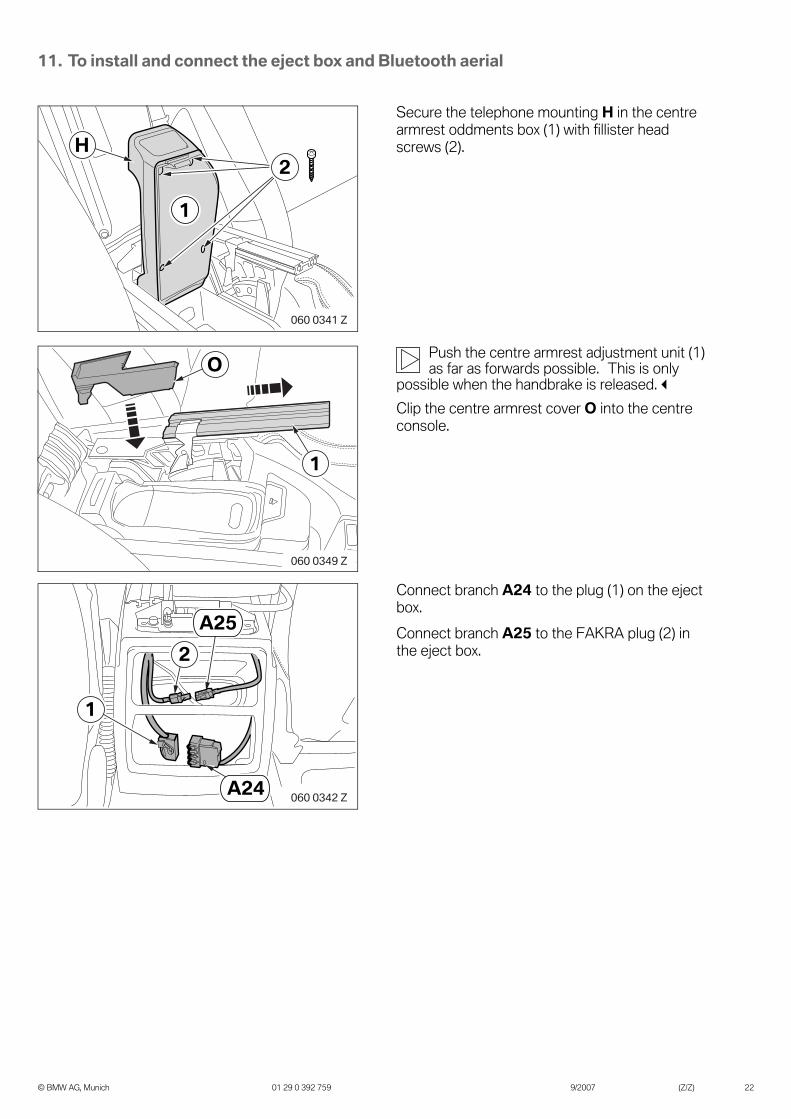
11. To install and connect the eject box and Bluetooth aerial
Secure the telephone mounting H in the centre armrest oddments box (1) with fillister head screws (2).
Push the centre armrest adjustment unit (1) as far as forwards possible. This is only
possible when the handbrake is released.
Clip the centre armrest cover O into the centre console.
Connect branch A24 to the plug (1) on the eject box.
Connect branch A25 to the FAKRA plug (2) in the eject box.
060 0341 Z
2H
1
O
1
060 0349 Z
060 0342 Z
1
2
A24
A25
© BMW AG, Munich 01 29 0 392 759 9/2007 (Z/Z) 22

12. To install and connect the hands-free microphone
Cars without SA 620 only
The arrow on the hands-free microphone L must point to the front of the car when
installed.
Clip the hands-free microphone L into the hands-free microphone trim C.
Cars without SA 620 and with SA 403 only
Unclip the sunroof button (1) from the standard trim.
Clip the sunroof button (1) and hands-free microphone trim C into the headlining trim S.
Connect the plug (2) to the sunroof button (1).
Connect branch A12 to the hands-free micro-phone L.
Tie back branch A13, it is not required.
Cars without SA 620 and without SA 403 only
Clip the hands-free microphone trim C into the headlining trim T.
C
L
060 0269 Z
060 0343 Z
1C
S
060 0344 Z
L
12
A12 A13
060 0345 Z
C
T
© BMW AG, Munich 01 29 0 392 759 9/2007 (Z/Z) 23
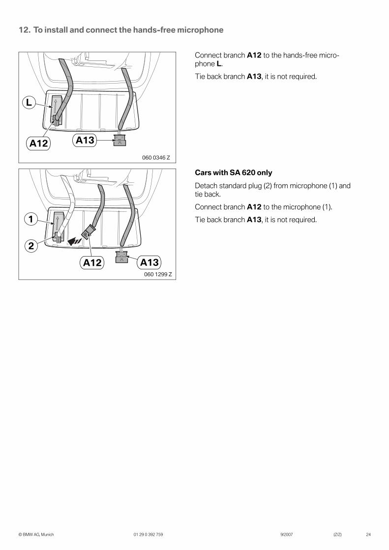
12. To install and connect the hands-free microphone
Connect branch A12 to the hands-free micro-phone L.
Tie back branch A13, it is not required.
Cars with SA 620 only
Detach standard plug (2) from microphone (1) and tie back.
Connect branch A12 to the microphone (1).
Tie back branch A13, it is not required.
060 0346 Z
A12
L
A13
060 1299 Z
A12
1
A13
2
© BMW AG, Munich 01 29 0 392 759 9/2007 (Z/Z) 24

13. Concluding work and coding
This retrofit system requires coding.
- Connect the battery
- Encode the retrofit with SSS (software service station) via the CIP path
- Conduct a brief test
- Register the mobile phone (see section 14)
- Conduct a function test
- Re-fit the car components as required
© BMW AG, Munich 01 29 0 392 759 9/2007 (Z/Z) 25

14. Pairing the mobile phone
Setting on the carThis car is not supplied with a Bluetooth code card. The Bluetooth code required for the registration process, an arbitrary number with up to 16 figures, can be freely selected.
- Switch on the ignition, the main menu will appear in the Control Display
- Open the information menu >i< in the Control Display
- Select menu point COMMUNICATION SETTINGS
- In the Bluetooth menu select SETTINGS
- Select and activate BLUETOOTH COMMUNICATION
Bluetooth is indicated as activated by a check in a square.
- Select menu point TELEPHONE.
- The follow appears: BLUETOOTH CAN BE CONNECTED IN THIS MENU
Preparations using the mobile phoneOther work must be completed on the mobile phone and the procedures differ from model to model, see the manual supplied with your mobile phone, for example in the following sections:
- Search for Bluetooth equipment
- Connect Bluetooth equipment
- Activate Bluetooth equipment
Concluding the pairing procedure- Select ADD DEVICE on the Control Display
- Enter a freely selectable Bluetooth code using the number pad on the Control Display and confirm your entry
- Enter the same Bluetooth code in the mobile phone using menu point BLUETOOTH PASSKEY
- The message HANDS-FREE ACCEPTED will appear on the mobile
- The registration process has been completed successfully
NotesIf the registration process was not completed successfully, switch off the ignition and repeat the entire process rapidly.
BMW recommends that phones only be used in Original BMW snap-in adapters. This is the only way to ensure a perfect connection via the external aerial. Otherwise poor reception may occur when using the telephone and interference when using the audio system.
Service informationIf the Bluetooth control module is replaced as part of service work, the mobile phone must be re-registered.
© BMW AG, Munich 01 29 0 392 759 9/2007 (Z/Z) 26

15. Circuit diagram (cars without ULF control unit already fitted only)
Branches not shown are not required and must be tied back.
11 X13
514
A25
*
X69
5A
29*
X11
575
A5*
X10
634
A28
*
X69
5A
29*
1
B40
0/L*
W18
/I*W
16/B
*
U40
0/K
*
X13
293�
A12
*1
2
39
21
119
211
31
30g
Cradle Key+
Cradle OnX
4545
A24
*X
1379
3A
31*
3211
17
11
21
135
X13
337/
A3*
0.35
BR
/WS
0.75
RT/
BR
0.5
BR
0.35
SW
VB
30g
X11
574
A26
*
A18
*
A19
*
X13
363�
A10
*
X12
28
VB
30g
X12
28
X11
012
10 A
F 80
0.35
WS
0.35
BR
/WS
MIC -
MIC +
A33
*
30gG
NG
N
X13
815
X13
812
0.75
RT/
BR
2
0.75
RT/
BR
X13
323/
A2*
3VB
30g
X12
28
X11
015
10 A
F 89
A46
A33
*
30g
0.75
RT/
BR
36
0.75
BR
060
1300
Z
© BMW AG, Munich 01 29 0 392 759 9/2007 (Z/Z) 27

15. Circuit diagram (cars without ULF control unit already fitted only)
Legend
All the designations marked with an asterisk (*) apply only to these installation instructions or this circuit diagram.
A46 Rear fuse holder
B* Roof aerial W16I* Bluetooth aerial W18K* ULF control unit U400L* Hands-free microphone B400
A2* SW Fakra plug casing X13322A3* SW Fakra socket casing X13337A5* WS Fakra socket casing X11575A10* BO/VI Fakra socket casing X13363A12* Socket casing, 3-pin SW X13293A18* Fibre optic cable connectorA19* Fibre optic cableA24* SW 18-pin socket casing X4545A25* SW Fakra plug casing X13514A26* GN Fakra socket casing X11574A28* Fibre optic cable casing, SW 2-pin X10634A29* Socket casing, WS 54-pin X695A31* Ring eyelet M6, terminal 31 pick-up X13793A33* Socket contact, terminal 30 pick-up
X1228 Terminal 30 connectorX11012 Socket casing, SW 41-pin (cars built after 09/05 only)X11015 Socket casing, GN 15-pin (cars built before 09/05 only)X13812 SW 16-pin socket casingX13815 Fibre optic cable casing, SW 2-pin
© BMW AG, Munich 01 29 0 392 759 9/2007 (Z/Z) 28

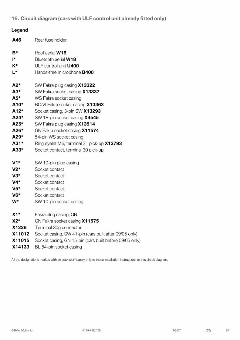
16. Circuit diagram (cars with ULF control unit already fitted only)
Branches not shown are not required and must be tied back.
11
X13
514
A25
*/
A29
*
A29
*
/W*
1
B40
0/L*
W18
/I*W
16/B
*
U40
0/K
*
X13
293�
A12
*1
2
39
1
X2*
1
13
2
3211
11
X13
337/
A3*
VB
30g
X11
574
A26
*X
1336
3�A
10*
X12
28
X11
012
10 A
F 80
0.35
WS
0.35
BR
/WS
MIC -
MIC +
0.35
SW
0.35
GE
0.35
TR
MIC -
MIC +
X14
133
X14
133
1921
1
A33
*
30g
0.75
RT/
BR
X13
323/
A2*
3VB
30g
X12
28
X11
015
10 A
F 89
A46
A33
*
30g
0.75
RT/
BR
13
2V
1*A
5*X
1*
30g
Cradle Key+
Cradle On
X45
45A
24*/1
5
0.35
BR
/WS
0.35
SW4
5
450.35
BR
/WS
0.35
GN
13V5*
V6*
V1* /W
*
V3*
V2*
V4*
1
31
X13
793
A31
*/
20.5
BR
VB
30g
X12
28
0.75
RT/
BR
X11
575
060
1331
Z
© BMW AG, Munich 01 29 0 392 759 9/2007 (Z/Z) 29
16. Circuit diagram (cars with ULF control unit already fitted only)
Legend
All the designations marked with an asterisk (*) apply only to these installation instructions or this circuit diagram.
A46 Rear fuse holder
B* Roof aerial W16I* Bluetooth aerial W18K* ULF control unit U400L* Hands-free microphone B400
A2* SW Fakra plug casing X13322A3* SW Fakra socket casing X13337A5* WS Fakra socket casingA10* BO/VI Fakra socket casing X13363A12* Socket casing, 3-pin SW X13293A24* SW 18-pin socket casing X4545A25* SW Fakra plug casing X13514A26* GN Fakra socket casing X11574A29* 54-pin WS socket casingA31* Ring eyelet M6, terminal 31 pick-up X13793A33* Socket contact, terminal 30 pick-up
V1* SW 10-pin plug casingV2* Socket contactV3* Socket contactV4* Socket contactV5* Socket contactV6* Socket contactW* SW 10-pin socket casing
X1* Fakra plug casing, GNX2* GN Fakra socket casing X11575X1228 Terminal 30g connectorX11012 Socket casing, SW 41-pin (cars built after 09/05 only)X11015 Socket casing, GN 15-pin (cars built before 09/05 only)X14133 BL 54-pin socket casing
© BMW AG, Munich 01 29 0 392 759 9/2007 (Z/Z) 30
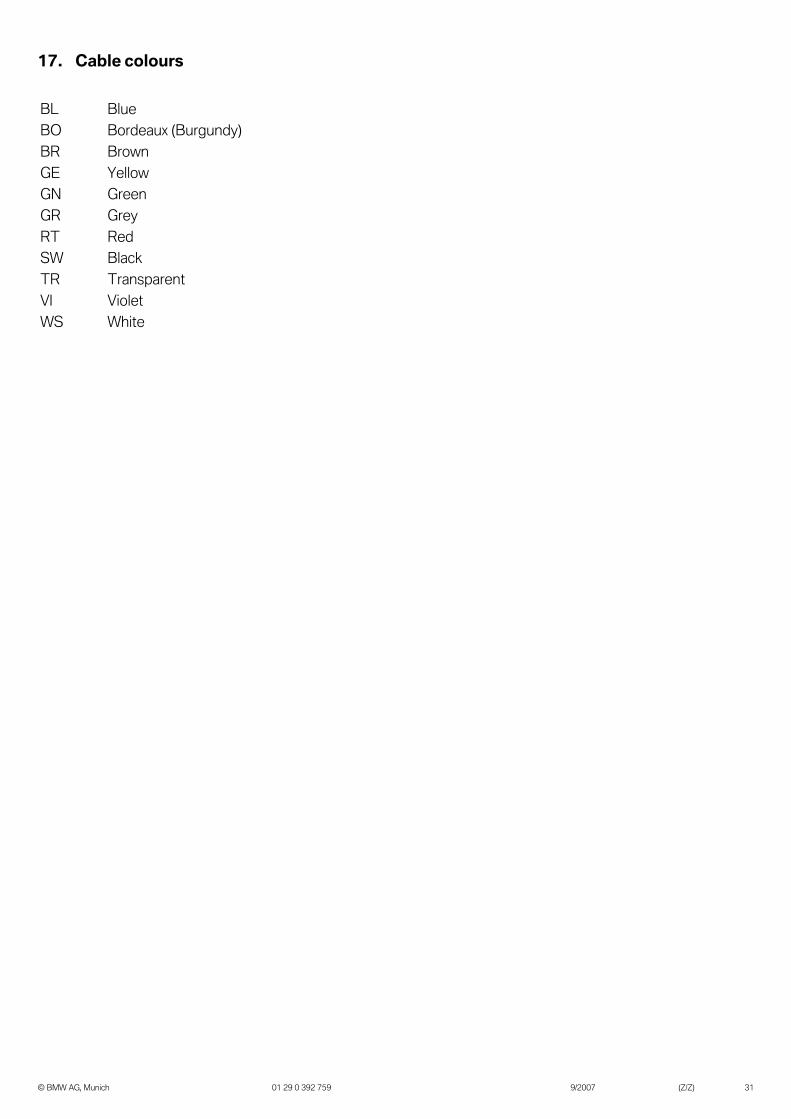
17. Cable colours
BL BlueBO Bordeaux (Burgundy)BR BrownGE YellowGN GreenGR GreyRT RedSW BlackTR TransparentVI VioletWS White
© BMW AG, Munich 01 29 0 392 759 9/2007 (Z/Z) 31


![Accessories Web[1] Bmw](https://img.pdfslide.net/doc/110x75/545f6819b1af9ff0588b4c2f/accessories-web1-bmw.jpg)