Embed Size (px)
Citation preview
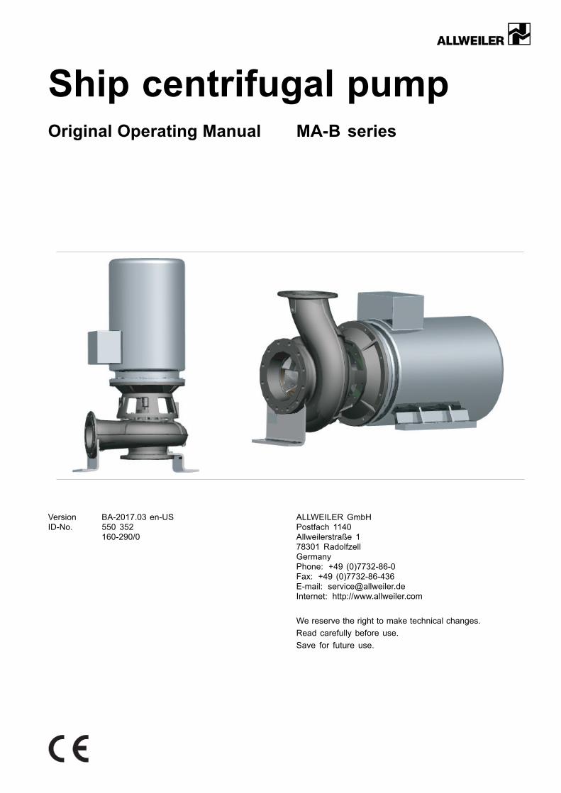
Ship centrifugal pumpOriginal Operating Manual MA-B series
Version BA-2017.03 en-USID-No. 550 352
160-290/0
ALLWEILER GmbHPostfach 1140Allweilerstraße 178301 RadolfzellGermanyPhone: +49 (0)7732-86-0Fax: +49 (0)7732-86-436E-mail: [email protected]: http://www.allweiler.com
We reserve the right to make technical changes.
Read carefully before use.
Save for future use.
Table of contents
Table of contents
1 About this document . . . . . . . . . . . . . . . . . . . . . . . . . . . . . . . 5
1.1 Target groups . . . . . . . . . . . . . . . . . . . . . . . . . . . . . . . . . 5
1.2 Other applicable documents . . . . . . . . . . . . . . . . 5
1.3 Warnings and symbols . . . . . . . . . . . . . . . . . . . . . . . 6
1.4 Technical terms . . . . . . . . . . . . . . . . . . . . . . . . . . . . . . . 6
2 Safety . . . . . . . . . . . . . . . . . . . . . . . . . . . . . . . . . . . . . . . . . . . . . . . . . 7
2.1 Intended use . . . . . . . . . . . . . . . . . . . . . . . . . . . . . . . . . . 7
2.2 General safety instructions . . . . . . . . . . . . . . . . . . 72.2.1 Product safety . . . . . . . . . . . . . . . . . . . . . . . . . . . . . . . . 72.2.2 Operator's obligations . . . . . . . . . . . . . . . . . . . . . . . . 82.2.3 Obligations of personnel . . . . . . . . . . . . . . . . . . . . . 8
2.3 Specific hazards . . . . . . . . . . . . . . . . . . . . . . . . . . . . . . 82.3.1 Hazardous pumped media . . . . . . . . . . . . . . . . . . 8
3 Layout and function . . . . . . . . . . . . . . . . . . . . . . . . . . . . . . . . 9
3.1 Labels . . . . . . . . . . . . . . . . . . . . . . . . . . . . . . . . . . . . . . . . . 93.1.1 Type plate . . . . . . . . . . . . . . . . . . . . . . . . . . . . . . . . . . . . . 93.1.2 Pump type code . . . . . . . . . . . . . . . . . . . . . . . . . . . . . . 9
3.2 Layout . . . . . . . . . . . . . . . . . . . . . . . . . . . . . . . . . . . . . . . . . 103.2.1 Vertical setup . . . . . . . . . . . . . . . . . . . . . . . . . . . . . . . . . 103.2.2 Horizontal setup . . . . . . . . . . . . . . . . . . . . . . . . . . . . . . 11
3.3 Shaft seals . . . . . . . . . . . . . . . . . . . . . . . . . . . . . . . . . . . . 123.3.1 Mechanical seals . . . . . . . . . . . . . . . . . . . . . . . . . . . . . 12
3.4 Auxiliary operating systems . . . . . . . . . . . . . . . . . 123.4.1 Automatic aspirator (if available) . . . . . . . . . . . . 12
4 Transport, storage and disposal . . . . . . . . . . . . . . . . . . 13
4.1 Transport . . . . . . . . . . . . . . . . . . . . . . . . . . . . . . . . . . . . . . 134.1.1 Unpacking and inspection on delivery . . . . . . 134.1.2 Lifting . . . . . . . . . . . . . . . . . . . . . . . . . . . . . . . . . . . . . . . . . . 13
4.2 Preservation . . . . . . . . . . . . . . . . . . . . . . . . . . . . . . . . . . 14
4.3 Storage . . . . . . . . . . . . . . . . . . . . . . . . . . . . . . . . . . . . . . . 14
4.4 Removing the preservative . . . . . . . . . . . . . . . . . . 14
4.5 Disposal . . . . . . . . . . . . . . . . . . . . . . . . . . . . . . . . . . . . . . . 15
5 Setup and connection . . . . . . . . . . . . . . . . . . . . . . . . . . . . . . 16
5.1 Preparing the setup . . . . . . . . . . . . . . . . . . . . . . . . . . 165.1.1 Checking the ambient conditions . . . . . . . . . . . 165.1.2 Preparing the installation site . . . . . . . . . . . . . . . 165.1.3 Removing the preservative . . . . . . . . . . . . . . . . . . 16
5.2 Fastening the pump . . . . . . . . . . . . . . . . . . . . . . . . . . 16
5.3 Planning the piping . . . . . . . . . . . . . . . . . . . . . . . . . . . 175.3.1 Specifying supports and flange
connections . . . . . . . . . . . . . . . . . . . . . . . . . . . . . . . . . . . 175.3.2 Specifying nominal diameters . . . . . . . . . . . . . . . 175.3.3 Specifying pipe lengths . . . . . . . . . . . . . . . . . . . . . . 175.3.4 Optimizing cross-section and direction
changes . . . . . . . . . . . . . . . . . . . . . . . . . . . . . . . . . . . . . . . 185.3.5 Discharging leaks . . . . . . . . . . . . . . . . . . . . . . . . . . . . 185.3.6 Providing safety and control devices
(recommended) . . . . . . . . . . . . . . . . . . . . . . . . . . . . . . 18
5.4 Connecting the pipes . . . . . . . . . . . . . . . . . . . . . . . . 185.4.1 Keeping the piping clean . . . . . . . . . . . . . . . . . . . . 185.4.2 Installing auxiliary pipes (if available) . . . . . . . 185.4.3 Installing the suction pipe . . . . . . . . . . . . . . . . . . . . 185.4.4 Installing the pressure pipe . . . . . . . . . . . . . . . . . . 185.4.5 Inspection for stress-free pipe
connections . . . . . . . . . . . . . . . . . . . . . . . . . . . . . . . . . . . 18
5.5 Installing the motor . . . . . . . . . . . . . . . . . . . . . . . . . . . 19
5.6 Electrical connection . . . . . . . . . . . . . . . . . . . . . . . . . 205.6.1 Connecting the motor . . . . . . . . . . . . . . . . . . . . . . . . 205.6.2 Checking the direction of rotation . . . . . . . . . . . 20
5.7 Fitting the guard sheets . . . . . . . . . . . . . . . . . . . . . . 20
6 Operation . . . . . . . . . . . . . . . . . . . . . . . . . . . . . . . . . . . . . . . . . . . . 21
6.1 Preparations for the initial start-up . . . . . . . . . . 216.1.1 Identifying the pump type . . . . . . . . . . . . . . . . . . . . 216.1.2 Removing the preservative . . . . . . . . . . . . . . . . . . 216.1.3 Preparing auxiliary systems (if
available) . . . . . . . . . . . . . . . . . . . . . . . . . . . . . . . . . . . . . 216.1.4 Filling and bleeding . . . . . . . . . . . . . . . . . . . . . . . . . . 216.1.5 Checking the direction of rotation . . . . . . . . . . . 21
6.2 Start-up . . . . . . . . . . . . . . . . . . . . . . . . . . . . . . . . . . . . . . . 226.2.1 Switching on . . . . . . . . . . . . . . . . . . . . . . . . . . . . . . . . . . 226.2.2 Switching off . . . . . . . . . . . . . . . . . . . . . . . . . . . . . . . . . . 22
6.3 Shutting down . . . . . . . . . . . . . . . . . . . . . . . . . . . . . . . . 23
6.4 Start-up following a shutdown period . . . . . . . 23
6.5 Operating the stand-by pump . . . . . . . . . . . . . . . 23
7 Maintenance . . . . . . . . . . . . . . . . . . . . . . . . . . . . . . . . . . . . . . . . . 24
7.1 Inspections . . . . . . . . . . . . . . . . . . . . . . . . . . . . . . . . . . . 24
7.2 Maintenance . . . . . . . . . . . . . . . . . . . . . . . . . . . . . . . . . . 247.2.1 Mechanical seals . . . . . . . . . . . . . . . . . . . . . . . . . . . . . 247.2.2 Cleaning the pump . . . . . . . . . . . . . . . . . . . . . . . . . . . 24
7.3 Dismounting . . . . . . . . . . . . . . . . . . . . . . . . . . . . . . . . . . 257.3.1 Returning the pump to the manufac-
turer . . . . . . . . . . . . . . . . . . . . . . . . . . . . . . . . . . . . . . . . . . . 257.3.2 Preparations for dismounting . . . . . . . . . . . . . . . . 257.3.3 Removal of the flanged motor . . . . . . . . . . . . . . . 26
7.4 Installing . . . . . . . . . . . . . . . . . . . . . . . . . . . . . . . . . . . . . . 267.4.1 Installation of the pump . . . . . . . . . . . . . . . . . . . . . . 267.4.2 Fitting the flanged motor or foot flanged
motor . . . . . . . . . . . . . . . . . . . . . . . . . . . . . . . . . . . . . . . . . . 27
7.5 Ordering spare parts . . . . . . . . . . . . . . . . . . . . . . . . . 28
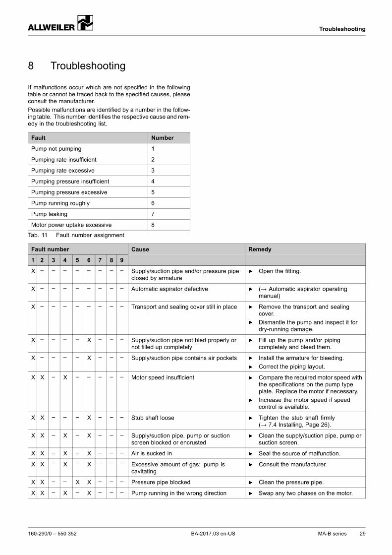
8 Troubleshooting . . . . . . . . . . . . . . . . . . . . . . . . . . . . . . . . . . . . 29
9 Appendix . . . . . . . . . . . . . . . . . . . . . . . . . . . . . . . . . . . . . . . . . . . . . 32
9.1 Sectional drawings . . . . . . . . . . . . . . . . . . . . . . . . . . . 329.1.1 Auxiliary connections . . . . . . . . . . . . . . . . . . . . . . . . 329.1.2 Part numbers and designations . . . . . . . . . . . . . 329.1.3 Sectional drawings . . . . . . . . . . . . . . . . . . . . . . . . . . . 33
9.2 Technical specifications . . . . . . . . . . . . . . . . . . . . . . 379.2.1 Stub shaft diameter at the shaft seal . . . . . . . 379.2.2 Ambient conditions . . . . . . . . . . . . . . . . . . . . . . . . . . . 379.2.3 Sound pressure level . . . . . . . . . . . . . . . . . . . . . . . . 379.2.4 Tightening torques . . . . . . . . . . . . . . . . . . . . . . . . . . . 38
2 MA-B series BA-2017.03 en-US 160-290/0 – 550 352
Table of contents
9.2.5 Cleaning agents . . . . . . . . . . . . . . . . . . . . . . . . . . . . . . 38
9.3 Spare parts for two years of continuousoperation in compliance with DIN24296 . . . . . . . . . . . . . . . . . . . . . . . . . . . . . . . . . . . . . . . . . 39
9.4 Declaration of harmlessness . . . . . . . . . . . . . . . . 40
9.5 Declaration of conformity according to ECMachine Directive . . . . . . . . . . . . . . . . . . . . . . . . . . . . 41
160-290/0 – 550 352 BA-2017.03 en-US MA-B series 3
Table of contents
List of figures
Fig. 1 Type plate (example) . . . . . . . . . . . . . . . . . . . . . . . . 9
Fig. 2 Pump type code (example) . . . . . . . . . . . . . . . . . . 9
Fig. 3 Vertical layout of MA-B . . . . . . . . . . . . . . . . . . . . . . 10
Fig. 4 Horizontal layout of MA-B . . . . . . . . . . . . . . . . . . . 11
Fig. 5 Automatic aspirator – example of verticalattachment . . . . . . . . . . . . . . . . . . . . . . . . . . . . . . . . . . . . 12
Fig. 6 Automatic aspirator – example of horizontalattachment . . . . . . . . . . . . . . . . . . . . . . . . . . . . . . . . . . . . 12
Fig. 7 Fastening the lifting gear to the pump unit ina vertical position . . . . . . . . . . . . . . . . . . . . . . . . . . . . . 13
Fig. 8 Fastening the lifting gear to the pump unit ina horizontal position . . . . . . . . . . . . . . . . . . . . . . . . . . 13
Fig. 9 Straight pipe lengths upstreamand downstream of the pump(recommended) . . . . . . . . . . . . . . . . . . . . . . . . . . . . . . 17
Fig. 10 Widening the stub shaft . . . . . . . . . . . . . . . . . . . . . . 19
Fig. 11 Motor assembly . . . . . . . . . . . . . . . . . . . . . . . . . . . . . . 19
Fig. 12 Widening the stub shaft . . . . . . . . . . . . . . . . . . . . . . 26
Fig. 13 Widening the stub shaft . . . . . . . . . . . . . . . . . . . . . . 27
Fig. 14 Motor assembly . . . . . . . . . . . . . . . . . . . . . . . . . . . . . . 27
Fig. 15 Sectional drawing . . . . . . . . . . . . . . . . . . . . . . . . . . . . 33
Fig. 16 Exploded drawing . . . . . . . . . . . . . . . . . . . . . . . . . . . . 34
Fig. 17 Sectional drawing . . . . . . . . . . . . . . . . . . . . . . . . . . . . 35
Fig. 18 Exploded drawing . . . . . . . . . . . . . . . . . . . . . . . . . . . . 36
List of tables
Tab. 1 Target groups and their duties . . . . . . . . . . . . . . 5
Tab. 2 Other applicable documents and theirpurpose . . . . . . . . . . . . . . . . . . . . . . . . . . . . . . . . . . . . . . . 5
Tab. 3 Warnings and consequences of disregardingthem .. . . . . . . . . . . . . . . . . . . . . . . . . . . . . . . . . . . . . . . . . . 6
Tab. 4 Symbols and their meaning . . . . . . . . . . . . . . . . . 6
Tab. 5 Technical terms and their meaning . . . . . . . . . 6
Tab. 6 Treatment for storage . . . . . . . . . . . . . . . . . . . . . . . . 14
Tab. 7 Measures to be taken if the pump is shutdown . . . . . . . . . . . . . . . . . . . . . . . . . . . . . . . . . . . . . . . . . . 23
Tab. 8 Measures will depend on the behavior of thepumped liquid . . . . . . . . . . . . . . . . . . . . . . . . . . . . . . . . 23
Tab. 9 Measures to be taken after prolongedshutdown periods . . . . . . . . . . . . . . . . . . . . . . . . . . . . 23
Tab. 10 Measures for return . . . . . . . . . . . . . . . . . . . . . . . . . . 25
Tab. 11 Fault number assignment . . . . . . . . . . . . . . . . . . . 29
Tab. 12 Troubleshooting list . . . . . . . . . . . . . . . . . . . . . . . . . . 31
Tab. 13 Abbreviations of the connectiondesignations . . . . . . . . . . . . . . . . . . . . . . . . . . . . . . . . . . 32
Tab. 14 Designations of components according topart numbers . . . . . . . . . . . . . . . . . . . . . . . . . . . . . . . . . 32
Tab. 15 Assignment of the pump and housing coversize to the stub shaft diameter . . . . . . . . . . . . . . 37
Tab. 16 Ambient conditions . . . . . . . . . . . . . . . . . . . . . . . . . . . 37
Tab. 17 Sound pressure level . . . . . . . . . . . . . . . . . . . . . . . . 37
Tab. 18 Tightening torques . . . . . . . . . . . . . . . . . . . . . . . . . . . 38
Tab. 19 Cleaning agents . . . . . . . . . . . . . . . . . . . . . . . . . . . . . . 38
Tab. 20 Spare parts for two years of continuousoperation . . . . . . . . . . . . . . . . . . . . . . . . . . . . . . . . . . . . . . 39
Tab. 21 Declaration of harmlessness . . . . . . . . . . . . . . . 40
Tab. 22 Declaration of conformity according to ECmachine directives . . . . . . . . . . . . . . . . . . . . . . . . . . . 41
4 MA-B series BA-2017.03 en-US 160-290/0 – 550 352
About this document
1 About this document
This manual
• Is part of the pump
• Applies to all pump series listed
• Describes safe and appropriate operation during all oper-ating phases
1.1 Target groups
Target group Duty
Operating company Keep this manual accessible at the equipment operating site;it may be needed for later use.
Make sure that personnel read and follow the instructions in thismanual and all other applicable documents, especially the safetyinstructions and warnings.
Observe any additional system-related rules and regulations.
Qualified personnel, fitter Read, observe and follow this manual and all other applicabledocuments, especially the safety instructions and warnings.
Tab. 1 Target groups and their duties
1.2 Other applicable documents
Document Purpose
Order data sheet Technical specifications, conditions of operation
Setup drawing Setup dimensions, connection dimensions etc.
Technical description Technical specifications, operating limits
Sectional drawing Sectional drawing, part numbers, component designations
Automatic aspirator operating manual Technical documentation
Supplier documentation Technical documentation for parts supplied by subcontractors
Spare parts list Ordering spare parts
Declaration of conformity Conformity with standardsContent of the declaration of conformity (→ 9.5 Declaration ofconformity according to EC Machine Directive, Page 41).
Tab. 2 Other applicable documents and their purpose
160-290/0 – 550 352 BA-2017.03 en-US MA-B series 5
About this document
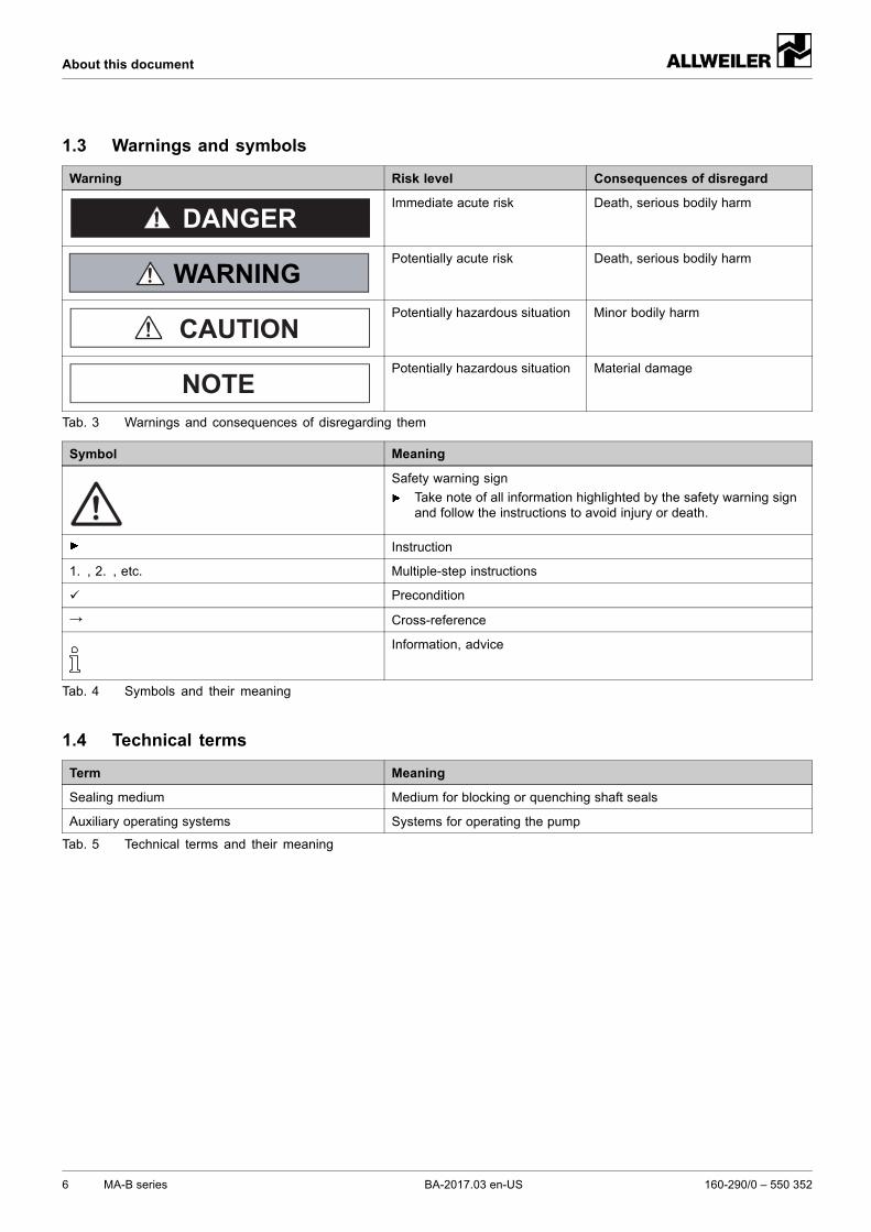
1.3 Warnings and symbols
Warning Risk level Consequences of disregard
DANGERImmediate acute risk Death, serious bodily harm
Potentially acute risk Death, serious bodily harm
CAUTIONPotentially hazardous situation Minor bodily harm
NOTEPotentially hazardous situation Material damage
Tab. 3 Warnings and consequences of disregarding them
Symbol Meaning
Safety warning sign
Take note of all information highlighted by the safety warning signand follow the instructions to avoid injury or death.
Instruction
1. , 2. , etc. Multiple-step instructions
Precondition
→ Cross-reference
Information, advice
Tab. 4 Symbols and their meaning
1.4 Technical terms
Term Meaning
Sealing medium Medium for blocking or quenching shaft seals
Auxiliary operating systems Systems for operating the pump
Tab. 5 Technical terms and their meaning
6 MA-B series BA-2017.03 en-US 160-290/0 – 550 352
Safety
2 Safety
The manufacturer accepts no liability for damages causedby disregarding any of the documentation.
2.1 Intended use
• Only use the pump for pumping fresh or seawater on ships.
• Adhere to the operating limits and size-dependent mini-mum flow rate.
• Avoid dry running:Damage such as destruction of the mechanical seal andplastic parts will occur within the first few seconds.– Make sure the pump is only operated with, and never
without, pumped liquid.
• Avoid cavitation:– Fully open the suction-side armature and do not use it
to adjust the flow rate.– Do not open the pressure-side armature beyond the
specified operating point.
• Avoid overheating:– Do not operate the pump while the pressure-side fitting
is closed.– Observe the minimum flow rate (→ order data sheet).
• Avoid damage to the motor:– Do not open the pressure-side armature beyond the
specified operating point.– Do not switch on the motor more than the maximum
permissible number of times per hour (→ manufac-turer's specifications).
• Consult the manufacturer about any other use of the pump.
• Pumps delivered without a motor must be assembled intoa pump unit according to the provisions of EC MachineDirective 2006/42/EC.
Prevention of obvious misuse (examples)
• Note the operating limits of the pump concerning temper-ature, pressure, flow rate and motor speed (→ order datasheet).
• The power consumed by the pump increases with a higherdensity of the pumped medium. To avoid overloading thepump or motor, comply with the specified density (→ orderdata sheet).Lower densities are permissible. Adapt the auxiliary sys-tems accordingly.
• When pumping liquids containing solids, you must firstconsult the manufacturer and the agreed limits must beadhered to (→ order data sheet).
• When using auxiliary systems, ensure there is a continuoussupply of the appropriate operating medium.
• Pumps used for pumping water must not be used for food-stuffs or drinking water. The use of the pump for foodstuffsor drinking water must be specified in the order data sheet.
• Only select an installation type specified in this operatingmanual. For example, the following are not allowed:– Overhead installation– Installation in the immediate vicinity of extreme heat or
cold sources– Installation too close to the wall
2.2 General safety instructions
Observe the following regulations before carrying out anywork.
2.2.1 Product safety
The pump has been constructed using state-of-the-art technol-ogy and the applicable technical safety rules. Nevertheless,operation of the pump can still present a risk for the life andhealth of the user or third parties, or the pump or other prop-erty can be damaged.
• Only operate the pump if it is in perfect technical conditionand only use it as intended, remaining aware of safety andrisks, and adhere to the instructions in this manual.
• Ensure this manual and all other applicable documentsremain complete, legible and accessible to personnel at alltimes.
• Refrain from any procedures and actions that wouldpresent a risk to personnel or third parties.
• In the event of any safety-relevant malfunctions, shut downthe pump immediately and have the malfunction correctedby the personnel responsible.
• In addition to the entire documentation for the product,comply with statutory or other safety and accident-preven-tion regulations and the applicable standards and guide-lines in the country where the system is operated.
160-290/0 – 550 352 BA-2017.03 en-US MA-B series 7
Safety
2.2.2 Operator's obligations
Safety-conscious operation
• Only operate the pump if it is in perfect technical conditionand only use it as intended, remaining aware of safety andrisks, and adhere to the instructions in this manual.
• Ensure that the following safety aspects are observed andmonitored:– Adherence to intended use– Statutory or other safety and accident-prevention reg-
ulations– Safety regulations governing the handling of haz-
ardous substances– Applicable standards and guidelines in the country
where the pump is operated
• Make protective equipment available.
Qualified personnel
• Make sure all personnel assigned to work on the pumphave read and understood this manual and all other appli-cable documents, especially the safety, maintenance andrepair information, before they start any work.
• Organize responsibilities, areas of competence and thesupervision of personnel.
• Ensure that all work is carried out by specialist techniciansonly:– Fitting, repair and maintenance work– Work on the electrical system
• Make sure that trainee personnel only work on the pumpunder the supervision of specialist technicians.
Safety equipment
• Provide the following safety equipment and verify its func-tionality:– For hot, cold and moving parts: on-site safety guards
for the pump– For possible electrostatic charges: provide the neces-
sary grounding
Warranty
• Obtain the manufacturer's approval prior to carrying outanymodifications, repairs or alterations during the warrantyperiod.
• Only use genuine parts or parts that have been approvedby the manufacturer.
2.2.3 Obligations of personnel
• All directions given on the pumpmust be followed (and keptlegible), e.g. the arrow indicating the sense of rotation andthe markings for fluid connections.
• Pump, coupling guard and components:– Do not step on them or use as a climbing aid– Do not use them to support boards, ramps or beams– Do not use them as a fixing point for winches or sup-
ports– Do not use them for storing paper or similar materials– Do not use hot pump or motor components as a heating
point– Do not de-ice using gas burners or similar tools
• Do not remove the safety guards for hot, cold or movingparts during operation.
• Use protective equipment if necessary.
• Only carry out work on the pump while it is not running.
• Disconnect the motor from its power supply and securewhen carrying out any installation or maintenance work.
• Reinstall the safety equipment on the pump as required byregulations after any work on the pump.
2.3 Specific hazards
2.3.1 Hazardous pumped media
• Observe the safety regulations for handling hazardoussubstances (e.g. hot, flammable, poisonous or potentiallyharmful) when handling hazardous pumped liquids.
• Use protective equipment when carrying out any work onthe pump.
8 MA-B series BA-2017.03 en-US 160-290/0 – 550 352
Layout and function
3 Layout and function
3.1 Labels
3.1.1 Type plate
11
10
13
12 4
5
6
1
2
3
9 8 7
Fig. 1 Type plate (example)
1 Pump number
2 Pump type code
3 Year of manufacture
4 Impeller diameter
5 Minimal efficiency index (MEI)
6 Eta efficiency (—.- = not specified)
7 Pump NPSH value
8 Density
9 Kinematic viscosity
10 Motor speed
11 Power consumption
12 Differential head
13 Flow rate
3.1.2 Pump type code
123456789
10
MA–B 80–315/41/310 U3.19D–V – W133–55/400
Fig. 2 Pump type code (example)
1 Series
2 Size (standard nominal diameter)
3 Nominal impeller diameter [mm]
4 Hydraulic number
5 Actual impeller diameter [mm]
6 Shaft seal
7 Setup type- V = vertical- H = horizontal
8 Material key
9 Diameter of motor shaft end [mm]
10 Outer diameter of motor flange [mm]
160-290/0 – 550 352 BA-2017.03 en-US MA-B series 9
Layout and function
3.2 Layout
3.2.1 Vertical setup
Fig. 3 Vertical layout of MA-B
1 Flanged motor
2 Intermediate ring
3 Stub shaft
4 Guard sheet
5 Motor bell housing
6 Mechanical seal
7 Housing cover
8 Volute casing
9 Impeller
10 Feet
10 MA-B series BA-2017.03 en-US 160-290/0 – 550 352
Layout and function
3.2.2 Horizontal setup
Fig. 4 Horizontal layout of MA-B
1 Foot flanged motor
2 Intermediate ring
3 Stub shaft
4 Guard sheet
5 Motor bell housing
6 Mechanical seal
7 Housing cover
8 Volute casing
9 Impeller
10 Foot
160-290/0 – 550 352 BA-2017.03 en-US MA-B series 11
Layout and function
3.3 Shaft seals
3.3.1 Mechanical seals
Mechanical seals have functional leaks.
• Single mechanical seal
3.4 Auxiliary operating systems
3.4.1 Automatic aspirator (if available)
Information on thematerial, functional description and elec-trical connection (→ automatic aspirator operating man-ual).
1
Fig. 5 Automatic aspirator – example of verticalattachment
1 Automatic aspirator
1
Fig. 6 Automatic aspirator – example of horizontalattachment
1 Automatic aspirator
The maintenance-free automatic aspirator:
• Used for automatic bleeding of pumps and suction pipes
• Operates according to the ejector principle with pressure-dependent control
• Suitable for clean, chemically neutral water
12 MA-B series BA-2017.03 en-US 160-290/0 – 550 352
Transport, storage and disposal
4 Transport, storage and disposal
4.1 Transport
For details of weight (→ documents for the particularorder).
4.1.1 Unpacking and inspection on delivery
1. Unpack the pump/pump unit upon delivery and inspect itfor transport damage.
2. Report any damage to the manufacturer immediately.
3. Dispose of packaging material according to local regula-tions.
4.1.2 Lifting
DANGER
Death or crushing of limbs caused by falling or overturningloads!
Use lifting gear appropriate for the total weight to be trans-ported.
Fasten the lifting gear as illustrated in the following.
Never fasten the lifting gear onto the motor eyebolt (unlessused as a safety device to prevent units with a high centerof gravity from tipping over).
Do not stand under suspended loads.
Set the load down on a level surface.Fig. 7 Fastening the lifting gear to the pump unit
in a vertical position
Fig. 8 Fastening the lifting gear to the pump unitin a horizontal position
Lift the pump/aggregate properly.
160-290/0 – 550 352 BA-2017.03 en-US MA-B series 13
Transport, storage and disposal
4.2 Preservation
Not necessary for non-rusting materials
Contact the manufacturer for recommendations regardingpreservatives.
NOTEMaterial damage due to inappropriate treatment for stor-age!
Treat the pump properly, inside and outside, for storage.
Preserving pump (observe the processing specifications ofthe manufacturers)
Duration[months]
Measures
Up to 6 All bare metal parts should be treated,inside and outside.
6 – 12 All bare metal parts should be treated,inside and outside.
Shrink-wrap the pump in plastic film.
12 – 24 All bare metal parts should be treated,inside and outside.
Shrink-wrap the pump in plastic film.
Use VCI anticorrosive.
Tab. 6 Treatment for storage
4.3 Storage
NOTEMaterial damage due to inappropriate storage!
Treat and store the pump properly.
1. Seal all openings with blank flanges, blind plugs or plasticcovers.
2. Make sure the storage room meets the following condi-tions:– Dry– Frost-free– Vibration-free
3. Turn the shaft once a month.
4. Make sure the shaft and bearing change their rotationalposition in the process.
4.4 Removing the preservative
Only necessary for pumps treated for storage.
WARNING
Risk of poisoning from preservatives and cleaning agentsin the foodstuffs and drinking water sector!
Only use cleaning agents which are compatible with thepumped liquid (→ 9.2.5 Cleaning agents, Page 38).
Completely remove all preservative.
NOTEHigh water pressure or spray water can damage bearings!
Do not clean bearing areas with a water or steam jet.
NOTEDamage to seals due to incorrect cleaning agent!
Ensure the cleaning agent does not corrode the seals.
1. Choose a suitable cleaning agent for the application.(→ 9.2.5 Cleaning agents, Page 38).
2. Dispose of cleaning agents in accordance with local regu-lations.
3. For storage times in excess of 6 months:– Replace the elastomer parts.– Check all elastomer parts (O-rings, shaft seals) for
proper elasticity and replace them if necessary.
14 MA-B series BA-2017.03 en-US 160-290/0 – 550 352
Transport, storage and disposal
4.5 Disposal
Plastic parts can be contaminated by poisonous or radioac-tive pumped liquids to such an extent that cleaning will beinsufficient.
WARNING
Risk of poisoning and environmental damage from thepumped liquid or oil!
Use protective equipment when carrying out any work onthe pump.
Prior to disposal of the pump:– Collect and dispose of any pumped liquid or oil which
is escaping in accordance with local regulations.– Neutralize residues of pumped medium in the pump.– Removing the preservative (→ 4.4 Removing the
preservative, Page 14).
Remove the plastic parts and dispose of them in accor-dance with local regulations.
Dispose of the pump in accordance with local regulations.
160-290/0 – 550 352 BA-2017.03 en-US MA-B series 15
Setup and connection
5 Setup and connection
NOTEMaterial damage due to distortion, or electrical currentflowing through the bearing!
Do not make any structural modifications to the pump unitor pump casing.
Do not carry out any welding work on the pump unit orpump casing.
NOTEMaterial damage caused by dirt!
Do not remove the transport seals until immediately priorto pump installation.
Do not remove any covers or transport and sealing coversuntil immediately prior to connecting the pipes to the pump.
NOTEMaterial damage due to unpermitted slant of the pump!
When at sea, ensure that the inclination of the pump is lessthan 30°.
5.1 Preparing the setup
5.1.1 Checking the ambient conditions
Make sure the required ambient conditions are fulfilled(→ 9.2.2 Ambient conditions, Page 37).
5.1.2 Preparing the installation site
Ensure the installation site meets the following conditions:– Pump is freely accessible from all sides– Sufficient space for the installation/removal of the pipes
and for maintenance and repair work, especially for theremoval and installation of the pump and the motor
– Pump unit not exposed to external vibrations (damageto bearings)
– Frost protection– Permitted inclination of the pump when at sea < 30°
5.1.3 Removing the preservative
If the pump is to be put into operation immediately afterinstallation and connection: Remove the preservativeprior to installation (→ 4.4 Removing the preservative,Page 14).
5.2 Fastening the pump
Keep transport seals safe.
1. Remove any transport seals.
2. Install the pump stress-free and fasten (→ setup drawing):
16 MA-B series BA-2017.03 en-US 160-290/0 – 550 352
Setup and connection
5.3 Planning the piping
5.3.1 Specifying supports and flange connections
NOTEMaterial damage due to excessive forces and torquesexerted by the piping on the pump!
Do not exceed the permissible limits.
1. Calculate the pipe forces taking every possible operatingcondition into account:– Cold/warm– Empty/full– Unpressurized/pressurized– Shift in position of flanges
2. Ensure the pipe supports have consistently low-frictionproperties and do not seize up due to corrosion.
5.3.2 Specifying nominal diameters
Keep the flow resistance in the pipes as low as possible.
1. Make sure the nominal suction pipe diameter is ≥ as pos-sible to the nominal suction flange diameter.– Recommended flow rate speed < 1 m/s
2. Make sure the nominal pressure pipe diameter is ≥ as pos-sible to the nominal outlet flange diameter.– Recommended flow rate speed < 3 m/s
5.3.3 Specifying pipe lengths
C
D
B
A
C
D
B
A
Fig. 9 Straight pipe lengths upstream and downstreamof the pump (recommended)
A > 5 x nominal suction pipe diameter
B Nominal suction pipe diameter
C Nominal pressure pipe diameter
D > 5 x nominal pressure pipe diameter
Maintain the recommended minimum values wheninstalling the pump.
Suction side: Shorter pipes are possible, but may impairthe hydraulic performance.
Pressure side: Shorter pipes are possible, but can result inincreased operating noise.
160-290/0 – 550 352 BA-2017.03 en-US MA-B series 17
Setup and connection
5.3.4 Optimizing cross-section and directionchanges
1. Avoid radii of curvature of less than 1.5 times the nominalpipe diameter.
2. Avoid abrupt changes in cross-sections along the piping.
5.3.5 Discharging leaks
WARNING
Risk of injury and poisoning due to hazardous pumpedliquids!
Collect any leaking pumped liquid safely, then dischargeand dispose of it in accordance with environmental regula-tions.
1. Provide equipment for collecting and discharging leakingliquids.
2. Ensure the free discharge of leaking liquids.
5.3.6 Providing safety and control devices(recommended)
Avoid impurities
1. Integrate a filter into the suction pipe.
2. To monitor impurities, install a differential pressure gaugewith a contact manometer.
Avoid reverse running
Install a non-return valve between the outlet flange and thestop valve to ensure the liquid does not flow back when thepump is switched off.
Avoid running empty
1. For suction operation: Install a foot valve in the suction pipeto prevent the pump and suction pipe from running emptyduring downtimes.
2. Use a suction strainer, depending on the solids content ofthe pumped fluid.
Make provisions for isolating and shutting off the pipes
For maintenance and repair work.
Provide shut-off devices in the suction and pressure pipes.
Allow the measurement of the operating conditions
1. Provide manometers for pressure measurements in suc-tion and pressure pipes.
2. Provide load monitors (overload and underload) on themotor side.
3. Provide for pump-side temperature measurements.
5.4 Connecting the pipes
5.4.1 Keeping the piping clean
NOTEMaterial damage due to impurities in the pump!
Make sure no impurities can enter the pump.
1. Clean all piping parts and armatures prior to assembly.
2. Ensure no flange seals protrude inwards.
3. Remove any blank flanges, plugs, protective foils and/orprotective paint from the flanges.
5.4.2 Installing auxiliary pipes (if available)
Observe the manufacturer's specifications for any auxiliaryoperating systems which are present.
1. Connect the auxiliary pipes to the auxiliary connections sothat they are stress-free and do not leak (→ setup drawing).
2. Avoid air pockets: Run the pipes with a continuous slopeup to the pump.
5.4.3 Installing the suction pipe
1. Remove the transport and sealing covers from the pump.
2. Avoid air pockets: Run the pipes with a continuous slopeup to the pump.
3. Ensure no seals protrude inwards.
4. For suction operation: Install a foot valve in the suction pipeto prevent the pump and suction pipe from running emptyduring downtimes.
5.4.4 Installing the pressure pipe
1. Remove the transport and sealing covers from the pump.
2. Install the pressure pipe.
3. Ensure no seals protrude inwards.
5.4.5 Inspection for stress-free pipe connections
Piping installed and cooled down
NOTEMaterial damage due to distorted pump casing
Ensure that all pipes are stress-free when connected to thepump.
1. Separate the pipe connecting flanges from the pump.
2. Check whether the pipes can be moved freely in all direc-tions within the expected range of expansion:– Nominal diameter < 150 mm: by hand– Nominal diameter > 150 mm: with a small lever
3. Make sure the flange surfaces are parallel.
4. Reconnect the pipe connecting flanges to the pump.
18 MA-B series BA-2017.03 en-US 160-290/0 – 550 352
Setup and connection
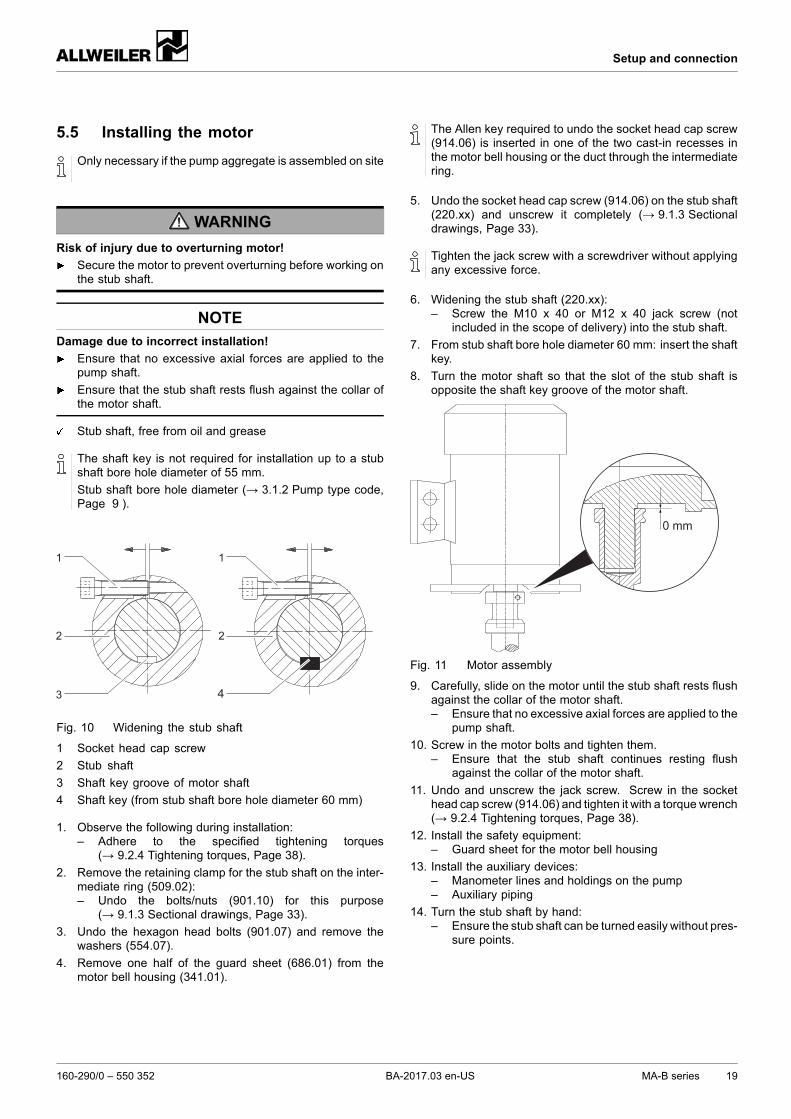
5.5 Installing the motor
Only necessary if the pump aggregate is assembled on site
WARNING
Risk of injury due to overturning motor!
Secure the motor to prevent overturning before working onthe stub shaft.
NOTEDamage due to incorrect installation!
Ensure that no excessive axial forces are applied to thepump shaft.
Ensure that the stub shaft rests flush against the collar ofthe motor shaft.
Stub shaft, free from oil and grease
The shaft key is not required for installation up to a stubshaft bore hole diameter of 55 mm.
Stub shaft bore hole diameter (→ 3.1.2 Pump type code,Page 9 ).
4
Fig. 10 Widening the stub shaft
1 Socket head cap screw
2 Stub shaft
3 Shaft key groove of motor shaft
4 Shaft key (from stub shaft bore hole diameter 60 mm)
1. Observe the following during installation:– Adhere to the specified tightening torques
(→ 9.2.4 Tightening torques, Page 38).
2. Remove the retaining clamp for the stub shaft on the inter-mediate ring (509.02):– Undo the bolts/nuts (901.10) for this purpose
(→ 9.1.3 Sectional drawings, Page 33).
3. Undo the hexagon head bolts (901.07) and remove thewashers (554.07).
4. Remove one half of the guard sheet (686.01) from themotor bell housing (341.01).
The Allen key required to undo the socket head cap screw(914.06) is inserted in one of the two cast-in recesses inthe motor bell housing or the duct through the intermediatering.
5. Undo the socket head cap screw (914.06) on the stub shaft(220.xx) and unscrew it completely (→ 9.1.3 Sectionaldrawings, Page 33).
Tighten the jack screw with a screwdriver without applyingany excessive force.
6. Widening the stub shaft (220.xx):– Screw the M10 x 40 or M12 x 40 jack screw (not
included in the scope of delivery) into the stub shaft.
7. From stub shaft bore hole diameter 60 mm: insert the shaftkey.
8. Turn the motor shaft so that the slot of the stub shaft isopposite the shaft key groove of the motor shaft.
0 mm
Fig. 11 Motor assembly
9. Carefully, slide on the motor until the stub shaft rests flushagainst the collar of the motor shaft.– Ensure that no excessive axial forces are applied to the
pump shaft.
10. Screw in the motor bolts and tighten them.– Ensure that the stub shaft continues resting flush
against the collar of the motor shaft.
11. Undo and unscrew the jack screw. Screw in the sockethead cap screw (914.06) and tighten it with a torque wrench(→ 9.2.4 Tightening torques, Page 38).
12. Install the safety equipment:– Guard sheet for the motor bell housing
13. Install the auxiliary devices:– Manometer lines and holdings on the pump– Auxiliary piping
14. Turn the stub shaft by hand:– Ensure the stub shaft can be turned easily without pres-
sure points.
160-290/0 – 550 352 BA-2017.03 en-US MA-B series 19
Setup and connection
5.6 Electrical connection
DANGER
Risk of electrocution!
Have all electrical work carried out by qualified electriciansonly.
5.6.1 Connecting the motor
Follow the instructions of the motor manufacturer.
1. Connect the motor according to the connection diagram.
2. Make sure no danger arises due to electric power.
3. Install an EMERGENCY STOP switch.
5.6.2 Checking the direction of rotation
This is only possible when the pump starts operation(→ 6.1 Preparations for the initial start-up, Page 21).
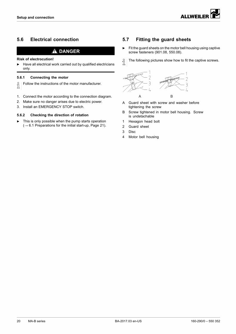
5.7 Fitting the guard sheets
Fit the guard sheets on themotor bell housing using captivescrew fasteners (901.08, 550.08).
The following pictures show how to fit the captive screws.
A B
A Guard sheet with screw and washer beforetightening the screw
B Screw tightened in motor bell housing. Screwis undetachable
1 Hexagon head bolt
2 Guard sheet
3 Disc
4 Motor bell housing
20 MA-B series BA-2017.03 en-US 160-290/0 – 550 352
Operation
6 Operation
6.1 Preparations for the initial start-up
6.1.1 Identifying the pump type
Identify the pump type (→ order data sheet).
The pump types vary e.g. with regard to the shaft seal,auxiliary systems.
6.1.2 Removing the preservative
Only necessary for pumps treated for storage.
(→ 4.4 Removing the preservative, Page 14).
6.1.3 Preparing auxiliary systems (if available)
The manufacturer does not accept any liability for damagecaused by installing or using a third-party or unapprovedauxiliary system.
6.1.4 Filling and bleeding
WARNING
Risk of injury and poisoning due to hazardous pumpedliquids!
Collect any leaking pumped liquid safely and dispose of itin accordance with environmental rules and requirements.
NOTEMaterial damage caused by dry running!
Make sure the pump is filled properly.
Without an automatic aspirator
Auxiliary systems ready for operation
1. Open the suction-side fitting.
2. Open the pressure-side fitting.
3. Fill the pump and the suction pipe with pumped medium.
4. Ensure that no pipe connections are leaking.
With an automatic aspirator
Auxiliary systems ready for operation
1. Open the suction-side fitting.
2. Close the pressure-side armature.
3. Suction operation (→ automatic aspirator operating man-ual).
4. Ensure that no pipe connections are leaking.
6.1.5 Checking the direction of rotation
Pump filled and bled
DANGER
Risk of death due to rotating parts!
Use protective equipment when carrying out any work onthe pump.
Keep an adequate distance to rotating parts.
NOTEMaterial damage caused by dry running!
Make sure the pump is filled properly.
1. Switch the motor on and immediately off again.
2. Check whether the motor's sense of rotation is the sameas that of the arrow on the pump.
3. If the direction of rotation is different: swap two phases.
160-290/0 – 550 352 BA-2017.03 en-US MA-B series 21
Operation
6.2 Start-up
6.2.1 Switching on
Pump aggregate set up and connected properly
All connections stress-free and sealed
Any available auxiliary systems are ready for operation
All safety equipment installed and tested for functionality
Pump prepared, filled and bled properly
DANGER
Risk of injury due to running pump!
Do not touch the running pump.
Ensure that the coupling guard is attached.
Do not carry out any work on the running pump.
Allow the pump to cool down completely before starting anywork.
Operate the pump only with the safety guarding installed.
DANGER
Risk of injury and poisoning due to pumped liquid spurtingout!
Use protective equipment when carrying out any work onthe pump.
NOTEMaterial damage caused by dry running!
Make sure the pump is filled properly.
NOTERisk of cavitation when throttling down the suction flowrate!
Fully open the suction-side armature and do not use it toadjust the flow rate.
Do not open the pressure-side armature beyond the oper-ating point.
NOTEMaterial damage caused by overheating!
Do not operate the pump for long periods with the pressure-side armature closed.
Observe the minimum flow rate (→ order data sheet).
1. Open the suction-side armature.
2. Close the pressure-side armature.
3. Switch on the motor and check it for smooth running.
4. Once the motor has reached its nominal speed, open thepressure-side armature slowly until the operating point isreached.
5. Make sure any temperature changes on pumps with hotpumped liquids are below 5 K/min.
6. After the first load under pressure and at operating temper-ature, check that the pump is not leaking.
6.2.2 Switching off
Pressure-side armature closed (recommended)
WARNING
Risk of injury due to hot pump parts!
Use protective equipment when carrying out any work onthe pump.
1. Switch off the motor.
2. Check all connecting bolts and tighten them if necessary.
22 MA-B series BA-2017.03 en-US 160-290/0 – 550 352
Operation
6.3 Shutting down
WARNING
Risk of injury and poisoning due to hazardous pumpedliquids!
Collect any leaking pumped liquid safely and dispose of itin accordance with environmental rules and requirements.
Take the following measures whenever the pump is shutdown:
Pump is Measure
...shut downfor a prolongedperiod
Perform measures accord-ing to the pumped liquid(→ Table 8 Measures willdepend on the behavior of thepumped liquid, Page 23).
...emptied Close the suction-side andpressure-side armatures.
...dismounted Isolate the motor from its powersupply and secure it againstunauthorized switch-on.
...put intostorage
Observe the storage instructions(→ 4.3 Storage, Page 14).
Tab. 7 Measures to be taken if the pump is shut down
Duration of shutdown (dependingon process)
Behaviorof pumpedmedium
Short Long
Solids sediment Flush thepump.
Flush thepump.
Solidifies/freezes,non-corrosive
Heat up orempty thepump andcontainers.
Empty thepump andcontainers.
Solidifies/freezes,corrosive
Heat up orempty thepump andcontainers.
Empty thepump andcontainers.
Treat thepump andcontainerswith preser-vative.
Remains liquid,non-corrosive
– –
Remains liquid,corrosive
– Empty thepump andcontainers.
Treat thepump andcontainerswith preser-vative.
Tab. 8 Measures will depend on the behaviorof the pumped liquid
6.4 Start-up following a shutdown period
1. If the pump is shut down for more than 2 years, take thefollowing measures before restoring it to service:
Shutdown period Measure
> 2 years Replace the elastomer seals(O-rings, shaft seal rings).
Tab. 9 Measures to be taken after prolongedshutdown periods
2. Carry out the same steps as for the initial start-up(→ 6.2 Start-up, Page 22).
6.5 Operating the stand-by pump
Stand-by pump filled and bled
Operate the stand-by pump at least once a week.
1. Completely open the suction-side armature.
2. Open the pressure-side armature far enough that thestand-by pump reaches its operating temperature and isheated uniformly. (→ 6.2.1 Switching on, Page 22).
160-290/0 – 550 352 BA-2017.03 en-US MA-B series 23
Maintenance
7 Maintenance
Trained customer service technicians are available forfitting and repair work. A pumped liquid certificate (DINsafety data sheet or safety certificate) must be presentedwhen requesting service.
7.1 Inspections
The inspection intervals depend on the operational strainon the pump.
DANGER
Risk of injury due to running pump!
Do not touch the running pump.
Do not carry out any work on the running pump.
WARNING
Risk of injury and poisoning due to hazardous pumpedliquids!
Use protective equipment when carrying out any work onthe pump.
1. Check at appropriate intervals:– Maintenance of minimum flow rate– Normal operating conditions unchanged– No impermissible vibrations
2. For trouble-free operation, always ensure the following:– No dry running– No leaks– No cavitation– Suction-side gate valves open– Unobstructed and clean filters– Sufficient pump inlet pressure– No unusual running noises or vibrations– No excessive leakage at the shaft seal– Proper functioning of auxiliary systems– Put the installed stand-by pump into operation at least
once a week
7.2 Maintenance
The connection between the stub shaft of the pump andthe motor shaft is rigid. Notes on bearing maintenance(→ operating manual provided by the motor manufacturer).
Mechanical seals are subject to natural wear, which islargely determined by the respective operating conditions.Therefore, general statements regarding their service lifecannot be made.
DANGER
Risk of injury due to running pump!
Do not touch the running pump.
Do not carry out any work on the running pump.
Disconnect the motor from its power supply and securewhen carrying out any installation or maintenance work.
DANGER
Risk of electrocution!
Have all electrical work carried out by qualified electriciansonly.
WARNING
Risk of injury and poisoning due to hazardous or hotpumped liquids!
Use protective equipment when carrying out any work onthe pump.
Allow the pump to cool down completely before commenc-ing any work.
Make sure the pump is depressurized.
Drain the pump, collect the pumped liquid safely and dis-pose of it in accordance with environmental regulations.
7.2.1 Mechanical seals
Mechanical seals have functional leaks (→ manufacturer'sspecifications).
In the event of a larger leak: Replace the mechanical sealand its auxiliary seals.
7.2.2 Cleaning the pump
NOTEHigh water pressure or spray water can damage bearings!
Do not clean bearing areas with a water or steam jet.
Clean large-scale grime from the pump.
24 MA-B series BA-2017.03 en-US 160-290/0 – 550 352
Maintenance
7.3 Dismounting
DANGER
Risk of injury due to running pump!
Do not touch the running pump.
Do not carry out any work on the running pump.
Disconnect the motor from its power supply and securewhen carrying out any installation or maintenance work.
DANGER
Risk of electrocution!
Have all electrical work carried out by qualified electriciansonly.
WARNING
Risk of injury and poisoning due to hazardous or hotpumped liquids!
Use protective equipment when carrying out any work onthe pump.
Allow the pump to cool down completely before commenc-ing any work.
Make sure the pump is depressurized.
Drain the pump, collect the pumped liquid safely and dis-pose of it in accordance with environmental regulations.
WARNING
Risk of injury due to heavy components!
Pay attention to the component weight. Lift and transportheavy components using suitable lifting gear.
Set down structural components safely and secure themagainst overturning or rolling away.
WARNING
Risk of injury during disassembly!
Secure the pressure-side gate valve against accidentalopening.
Depressurize the blocking pressure system, if available.
Wear protective gloves as wear or damage to componentscan make their edges very sharp.
Remove spring-loaded components (e.g. mechanical seal,tensioned bearing, valves etc.) carefully, as componentscan be ejected by the spring tension.
Observe the manufacturer's specifications (e.g. for themotor, coupling, mechanical seal, blocking pressure sys-tem, cardan shaft, gear boxes, belt drive etc.).
7.3.1 Returning the pump to the manufacturer
Pump depressurized
Pump completely empty
Electrical connections disconnected and motor securedagainst being switched on again
Pump cooled down
Auxiliary systems shut down, depressurized and emptied
Pressure gauge lines, pressure gauge and holdings dis-mounted
1. Fit any transport seals.
2. Enclose a truthful, and fully completed, safety certificatewhen returning pumps or components to the manufacturer.(→ 9.4 Declaration of harmlessness, Page 40).
Repair carried out Measure for return
...at the customer'spremises
Return the defectivecomponent to themanufacturer.
...at themanufacturer'spremises
Flush the pump anddecontaminate it if it wasused to pump hazardousmedia.
Return the complete pump(not disassembled) to themanufacturer.
...at themanufacturer'spremises forwarranty repairs
Only if the pumped mediais hazardous: flush anddecontaminate the pump.
Return the complete pump(not disassembled) to themanufacturer.
Tab. 10 Measures for return
7.3.2 Preparations for dismounting
Pump depressurized
Pump completely empty, flushed and decontaminated
Electrical connections disconnected and motor securedagainst being switched on again
Pump cooled down
Auxiliary systems shut down, depressurized and emptied
Pressure gauge lines, pressure gauge and holdings dis-mounted
Guard sheets removed
In production, the pumps are constructed to a standardprocess. Bearing and shaft seals can be replaced withoutremoving the motor, volute casing or piping.
When dismounting, observe the following:– Mark the correct installation location and position of all
components before dismantling them.– Dismantle components concentrically without canting.– Dismount the pump (→ sectional drawing).
160-290/0 – 550 352 BA-2017.03 en-US MA-B series 25
Maintenance
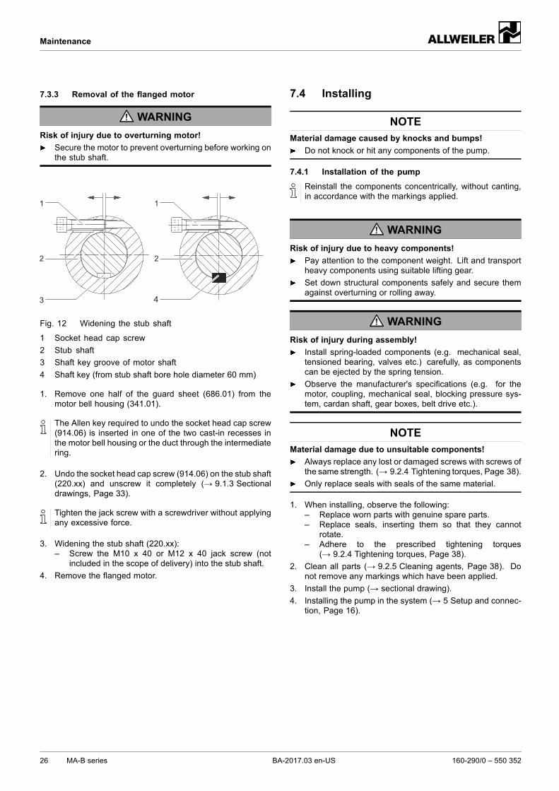
7.3.3 Removal of the flanged motor
WARNING
Risk of injury due to overturning motor!
Secure the motor to prevent overturning before working onthe stub shaft.
4
Fig. 12 Widening the stub shaft
1 Socket head cap screw
2 Stub shaft
3 Shaft key groove of motor shaft
4 Shaft key (from stub shaft bore hole diameter 60 mm)
1. Remove one half of the guard sheet (686.01) from themotor bell housing (341.01).
The Allen key required to undo the socket head cap screw(914.06) is inserted in one of the two cast-in recesses inthe motor bell housing or the duct through the intermediatering.
2. Undo the socket head cap screw (914.06) on the stub shaft(220.xx) and unscrew it completely (→ 9.1.3 Sectionaldrawings, Page 33).
Tighten the jack screw with a screwdriver without applyingany excessive force.
3. Widening the stub shaft (220.xx):– Screw the M10 x 40 or M12 x 40 jack screw (not
included in the scope of delivery) into the stub shaft.
4. Remove the flanged motor.
7.4 Installing
NOTEMaterial damage caused by knocks and bumps!
Do not knock or hit any components of the pump.
7.4.1 Installation of the pump
Reinstall the components concentrically, without canting,in accordance with the markings applied.
WARNING
Risk of injury due to heavy components!
Pay attention to the component weight. Lift and transportheavy components using suitable lifting gear.
Set down structural components safely and secure themagainst overturning or rolling away.
WARNING
Risk of injury during assembly!
Install spring-loaded components (e.g. mechanical seal,tensioned bearing, valves etc.) carefully, as componentscan be ejected by the spring tension.
Observe the manufacturer's specifications (e.g. for themotor, coupling, mechanical seal, blocking pressure sys-tem, cardan shaft, gear boxes, belt drive etc.).
NOTEMaterial damage due to unsuitable components!
Always replace any lost or damaged screws with screws ofthe same strength. (→ 9.2.4 Tightening torques, Page 38).
Only replace seals with seals of the same material.
1. When installing, observe the following:– Replace worn parts with genuine spare parts.– Replace seals, inserting them so that they cannot
rotate.– Adhere to the prescribed tightening torques
(→ 9.2.4 Tightening torques, Page 38).
2. Clean all parts (→ 9.2.5 Cleaning agents, Page 38). Donot remove any markings which have been applied.
3. Install the pump (→ sectional drawing).
4. Installing the pump in the system (→ 5 Setup and connec-tion, Page 16).
26 MA-B series BA-2017.03 en-US 160-290/0 – 550 352
Maintenance
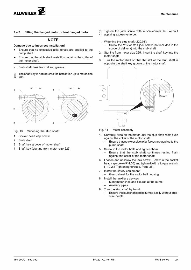
7.4.2 Fitting the flanged motor or foot flanged motor
NOTEDamage due to incorrect installation!
Ensure that no excessive axial forces are applied to thepump shaft.
Ensure that the stub shaft rests flush against the collar ofthe motor shaft.
Stub shaft, free from oil and grease
The shaft key is not required for installation up to motor size200.
4
Fig. 13 Widening the stub shaft
1 Socket head cap screw
2 Stub shaft
3 Shaft key groove of motor shaft
4 Shaft key (starting from motor size 225)
Tighten the jack screw with a screwdriver, but withoutapplying excessive force.
1. Widening the stub shaft (220.01):– Screw the M12 or M14 jack screw (not included in the
scope of delivery) into the stub shaft
2. Starting from motor size 225: Insert the shaft key into themotor shaft.
3. Turn the motor shaft so that the slot of the stub shaft isopposite the shaft key groove of the motor shaft.
0 mm
Fig. 14 Motor assembly
4. Carefully, slide on the motor until the stub shaft rests flushagainst the collar of the motor shaft.– Ensure that no excessive axial forces are applied to the
pump shaft.
5. Screw in the motor bolts and tighten them.– Ensure that the stub shaft continues resting flush
against the collar of the motor shaft.
6. Loosen and unscrew the jack screw. Screw in the sockethead cap screw (914.06) and tighten it with a torque wrench(→ 9.2.4 Tightening torques, Page 38).
7. Install the safety equipment:– Guard sheet for the motor bell housing
8. Install the auxiliary devices:– Manometer lines and fixtures at the pump– Auxiliary pipes
9. Turn the stub shaft by hand:– Ensure the stub shaft can be turned easily without pres-
sure points.
160-290/0 – 550 352 BA-2017.03 en-US MA-B series 27
Maintenance
7.5 Ordering spare parts
To facilitate replacement in the event of faults, we recom-mend keeping complete insert units or spare pumps avail-able on site.
The application guidelines described in DIN 24296 rec-ommend provisions for two years of continuous use(→ 9.3 Spare parts for two years of continuous operationin compliance with DIN 24296, Page 39).
Keep the following information ready to hand when order-ing spare parts (→ type plate):– Pump type– Pump number– Year of manufacture– Part number– Designation– Quantity
28 MA-B series BA-2017.03 en-US 160-290/0 – 550 352
Troubleshooting
8 Troubleshooting
If malfunctions occur which are not specified in the followingtable or cannot be traced back to the specified causes, pleaseconsult the manufacturer.
Possible malfunctions are identified by a number in the follow-ing table. This number identifies the respective cause and rem-edy in the troubleshooting list.
Fault Number
Pump not pumping 1
Pumping rate insufficient 2
Pumping rate excessive 3
Pumping pressure insufficient 4
Pumping pressure excessive 5
Pump running roughly 6
Pump leaking 7
Motor power uptake excessive 8
Tab. 11 Fault number assignment
Fault number
1 2 3 4 5 6 7 8 9
Cause Remedy
X – – – – – – – – Supply/suction pipe and/or pressure pipeclosed by armature
Open the fitting.
X – – – – – – – – Automatic aspirator defective (→ Automatic aspirator operatingmanual)
X – – – – – – – – Transport and sealing cover still in place Remove the transport and sealingcover.
Dismantle the pump and inspect it fordry-running damage.
X – – – – X – – – Supply/suction pipe not bled properly ornot filled up completely
Fill up the pump and/or pipingcompletely and bleed them.
X – – – – X – – – Supply/suction pipe contains air pockets Install the armature for bleeding.
Correct the piping layout.
X X – X – – – – – Motor speed insufficient Compare the required motor speed withthe specifications on the pump typeplate. Replace the motor if necessary.
Increase the motor speed if speedcontrol is available.
X X – – – X – – – Stub shaft loose Tighten the stub shaft firmly(→ 7.4 Installing, Page 26).
X X – X – X – – – Supply/suction pipe, pump or suctionscreen blocked or encrusted
Clean the supply/suction pipe, pump orsuction screen.
X X – X – X – – – Air is sucked in Seal the source of malfunction.
X X – X – X – – – Excessive amount of gas: pump iscavitating
Consult the manufacturer.
X X – – X X – – – Pressure pipe blocked Clean the pressure pipe.
X X – X – X – – – Pump running in the wrong direction Swap any two phases on the motor.
160-290/0 – 550 352 BA-2017.03 en-US MA-B series 29
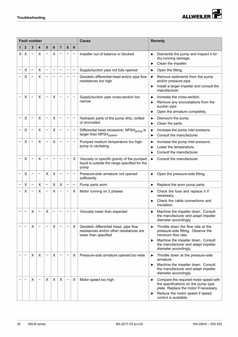
Troubleshooting
Fault number
1 2 3 4 5 6 7 8 9
Cause Remedy
X X – X – X – – – Impeller out of balance or blocked Dismantle the pump and inspect it fordry-running damage.
Clean the impeller.
– X – X – – – – – Supply/suction pipe not fully opened Open the fitting.
– X – X – – – – – Geodetic differential head and/or pipe flowresistances too high
Remove sediments from the pumpand/or pressure pipe.
Install a larger impeller and consult themanufacturer.
– X – X – X – – – Supply/suction pipe cross-section toonarrow
Increase the cross-section.
Remove any encrustations from thesuction pipe.
Open the armature completely.
– X – X – X – – – Hydraulic parts of the pump dirty, clottedor encrusted
Dismount the pump.
Clean the parts.
– X – X – X – – – Differential head excessive: NPSHpump islarger than NPSHsystem
Increase the pump inlet pressure.
Consult the manufacturer.
– X – X – X – – – Pumped medium temperature too high:pump is cavitating
Increase the pump inlet pressure.
Lower the temperature.
Consult the manufacturer.
– X – X – – – – X Viscosity or specific gravity of the pumpedliquid is outside the range specified for thepump
Consult the manufacturer.
– X – – X X – – – Pressure-side armature not openedsufficiently
Open the pressure-side fitting.
– X – X – X X – – Pump parts worn Replace the worn pump parts.
– X – X – X – – X Motor running on 2 phases Check the fuse and replace it ifnecessary.
Check the cable connections andinsulation.
– – X – X – – – – Viscosity lower than expected Machine the impeller down. Consultthe manufacturer and adapt impellerdiameter accordingly.
– – X – – X – – X Geodetic differential head, pipe flowresistances and/or other resistances arelower than specified
Throttle down the flow rate at thepressure-side fitting. Observe theminimum flow rate.
Machine the impeller down. Consultthe manufacturer and adapt impellerdiameter accordingly.
– – X X – X – – X Pressure-side armature opened too wide Throttle down at the pressure-sidearmature.
Machine the impeller down. Consultthe manufacturer and adapt impellerdiameter accordingly.
– – X – X X X – X Motor speed too high Compare the required motor speed withthe specifications on the pump typeplate. Replace the motor if necessary.
Reduce the motor speed if speedcontrol is available.
30 MA-B series BA-2017.03 en-US 160-290/0 – 550 352
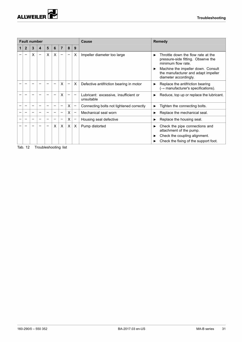
Troubleshooting
Fault number
1 2 3 4 5 6 7 8 9
Cause Remedy
– – X – X X – – X Impeller diameter too large Throttle down the flow rate at thepressure-side fitting. Observe theminimum flow rate.
Machine the impeller down. Consultthe manufacturer and adapt impellerdiameter accordingly.
– – – – – – X – X Defective antifriction bearing in motor Replace the antifriction bearing(→ manufacturer's specifications).
– – – – – – X – – Lubricant: excessive, insufficient orunsuitable
Reduce, top up or replace the lubricant.
– – – – – – – X – Connecting bolts not tightened correctly Tighten the connecting bolts.
– – – – – – – X – Mechanical seal worn Replace the mechanical seal.
– – – – – – – X – Housing seal defective Replace the housing seal.
– – – – – X X X X Pump distorted Check the pipe connections andattachment of the pump.
Check the coupling alignment.
Check the fixing of the support foot.
Tab. 12 Troubleshooting list
160-290/0 – 550 352 BA-2017.03 en-US MA-B series 31
Appendix
9 Appendix
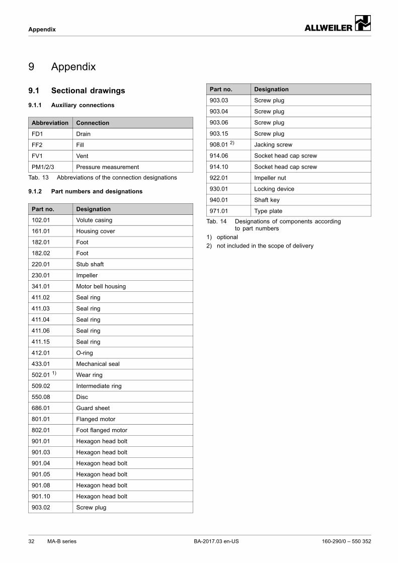
9.1 Sectional drawings
9.1.1 Auxiliary connections
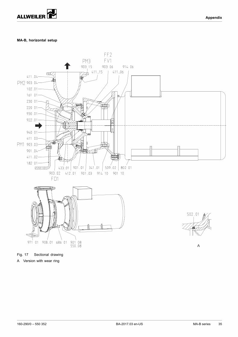
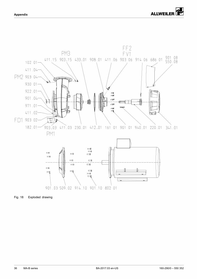
Abbreviation Connection
FD1 Drain
FF2 Fill
FV1 Vent
PM1/2/3 Pressure measurement
Tab. 13 Abbreviations of the connection designations
9.1.2 Part numbers and designations
Part no. Designation
102.01 Volute casing
161.01 Housing cover
182.01 Foot
182.02 Foot
220.01 Stub shaft
230.01 Impeller
341.01 Motor bell housing
411.02 Seal ring
411.03 Seal ring
411.04 Seal ring
411.06 Seal ring
411.15 Seal ring
412.01 O-ring
433.01 Mechanical seal
502.01 1) Wear ring
509.02 Intermediate ring
550.08 Disc
686.01 Guard sheet
801.01 Flanged motor
802.01 Foot flanged motor
901.01 Hexagon head bolt
901.03 Hexagon head bolt
901.04 Hexagon head bolt
901.05 Hexagon head bolt
901.08 Hexagon head bolt
901.10 Hexagon head bolt
903.02 Screw plug
Part no. Designation
903.03 Screw plug
903.04 Screw plug
903.06 Screw plug
903.15 Screw plug
908.01 2) Jacking screw
914.06 Socket head cap screw
914.10 Socket head cap screw
922.01 Impeller nut
930.01 Locking device
940.01 Shaft key
971.01 Type plate
Tab. 14 Designations of components accordingto part numbers
1) optional
2) not included in the scope of delivery
32 MA-B series BA-2017.03 en-US 160-290/0 – 550 352
Appendix
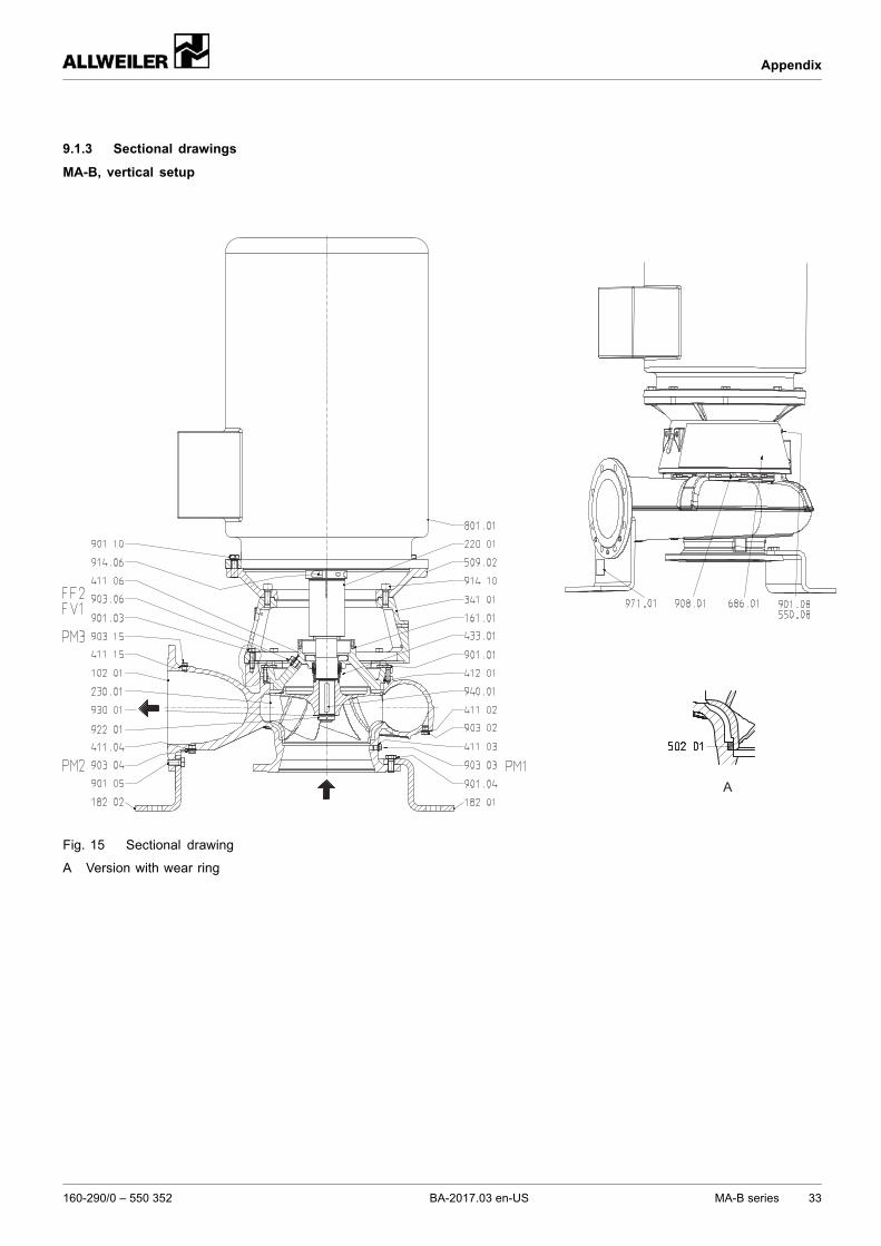
9.1.3 Sectional drawings
MA-B, vertical setup
A
Fig. 15 Sectional drawing
A Version with wear ring
160-290/0 – 550 352 BA-2017.03 en-US MA-B series 33
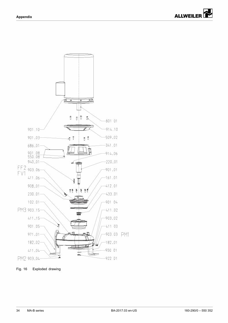
Appendix
Fig. 16 Exploded drawing
34 MA-B series BA-2017.03 en-US 160-290/0 – 550 352
Appendix
MA-B, horizontal setup
A
Fig. 17 Sectional drawing
A Version with wear ring
160-290/0 – 550 352 BA-2017.03 en-US MA-B series 35
Appendix
Fig. 18 Exploded drawing
36 MA-B series BA-2017.03 en-US 160-290/0 – 550 352
Appendix
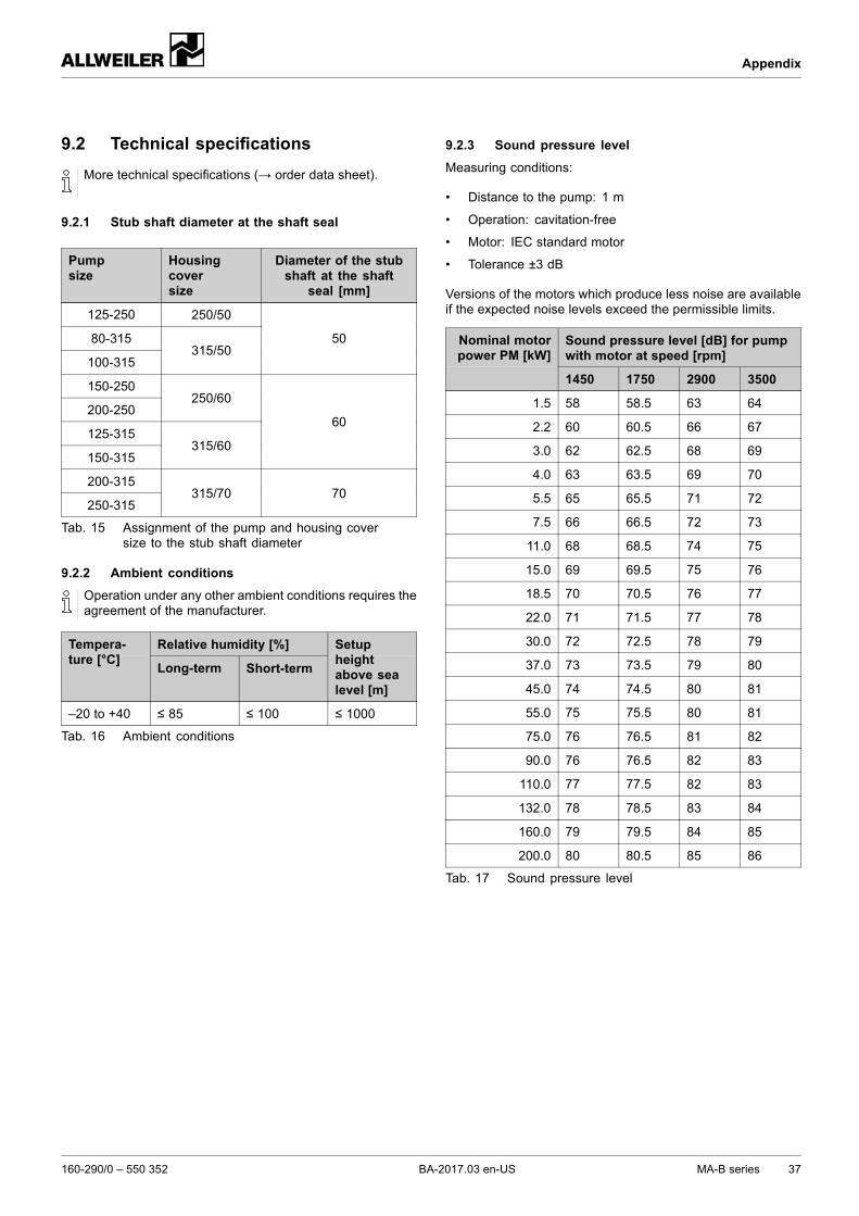
9.2 Technical specifications
More technical specifications (→ order data sheet).
9.2.1 Stub shaft diameter at the shaft seal
Pumpsize
Housingcoversize
Diameter of the stubshaft at the shaft
seal [mm]
125-250 250/50
80-315
100-315315/50
50
150-250
200-250250/60
125-315
150-315315/60
60
200-315
250-315315/70 70
Tab. 15 Assignment of the pump and housing coversize to the stub shaft diameter
9.2.2 Ambient conditions
Operation under any other ambient conditions requires theagreement of the manufacturer.
Relative humidity [%]Tempera-ture [°C]
Long-term Short-term
Setupheightabove sealevel [m]
–20 to +40 ≤ 85 ≤ 100 ≤ 1000
Tab. 16 Ambient conditions
9.2.3 Sound pressure level
Measuring conditions:
• Distance to the pump: 1 m
• Operation: cavitation-free
• Motor: IEC standard motor
• Tolerance ±3 dB
Versions of the motors which produce less noise are availableif the expected noise levels exceed the permissible limits.
Sound pressure level [dB] for pumpwith motor at speed [rpm]
Nominal motorpower PM [kW]
1450 1750 2900 3500
1.5 58 58.5 63 64
2.2 60 60.5 66 67
3.0 62 62.5 68 69
4.0 63 63.5 69 70
5.5 65 65.5 71 72
7.5 66 66.5 72 73
11.0 68 68.5 74 75
15.0 69 69.5 75 76
18.5 70 70.5 76 77
22.0 71 71.5 77 78
30.0 72 72.5 78 79
37.0 73 73.5 79 80
45.0 74 74.5 80 81
55.0 75 75.5 80 81
75.0 76 76.5 81 82
90.0 76 76.5 82 83
110.0 77 77.5 82 83
132.0 78 78.5 83 84
160.0 79 79.5 84 85
200.0 80 80.5 85 86
Tab. 17 Sound pressure level
160-290/0 – 550 352 BA-2017.03 en-US MA-B series 37
Appendix
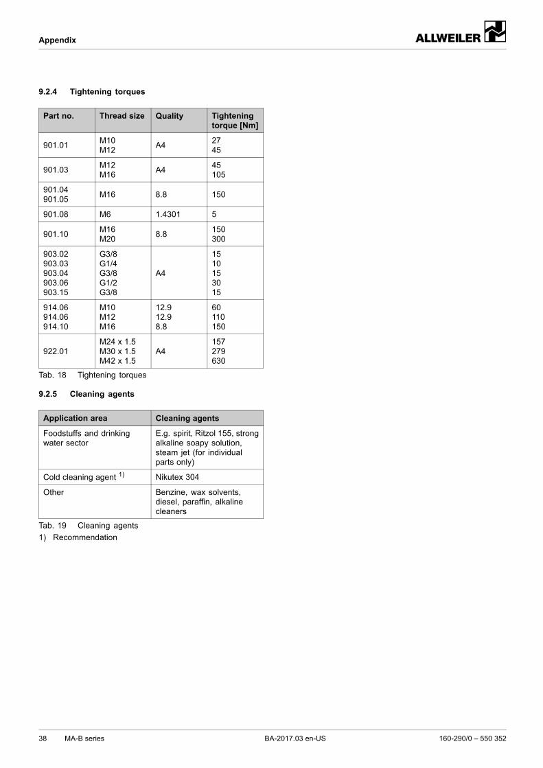
9.2.4 Tightening torques
Part no. Thread size Quality Tighteningtorque [Nm]
901.01M10M12
A42745
901.03M12M16
A445105
901.04901.05
M16 8.8 150
901.08 M6 1.4301 5
901.10M16M20
8.8150300
903.02903.03903.04903.06903.15
G3/8G1/4G3/8G1/2G3/8
A4
1510153015
914.06914.06914.10
M10M12M16
12.912.98.8
60110150
922.01M24 x 1.5M30 x 1.5M42 x 1.5
A4157279630
Tab. 18 Tightening torques
9.2.5 Cleaning agents
Application area Cleaning agents
Foodstuffs and drinkingwater sector
E.g. spirit, Ritzol 155, strongalkaline soapy solution,steam jet (for individualparts only)
Cold cleaning agent 1) Nikutex 304
Other Benzine, wax solvents,diesel, paraffin, alkalinecleaners
Tab. 19 Cleaning agents
1) Recommendation
38 MA-B series BA-2017.03 en-US 160-290/0 – 550 352
Appendix
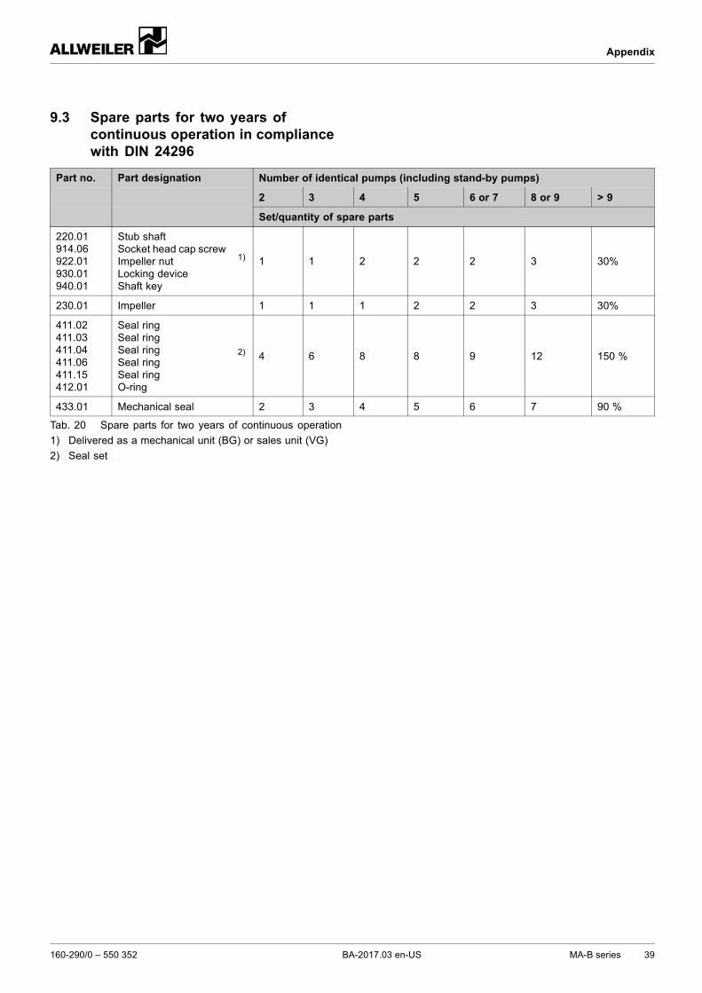
9.3 Spare parts for two years ofcontinuous operation in compliancewith DIN 24296
Number of identical pumps (including stand-by pumps)
2 3 4 5 6 or 7 8 or 9 > 9
Part no. Part designation
Set/quantity of spare parts
220.01914.06922.01930.01940.01
Stub shaftSocket head cap screwImpeller nutLocking deviceShaft key
1) 1 1 2 2 2 3 30%
230.01 Impeller 1 1 1 2 2 3 30%
411.02411.03411.04411.06411.15412.01
Seal ringSeal ringSeal ringSeal ringSeal ringO-ring
2) 4 6 8 8 9 12 150 %
433.01 Mechanical seal 2 3 4 5 6 7 90 %
Tab. 20 Spare parts for two years of continuous operation
1) Delivered as a mechanical unit (BG) or sales unit (VG)
2) Seal set
160-290/0 – 550 352 BA-2017.03 en-US MA-B series 39
Appendix
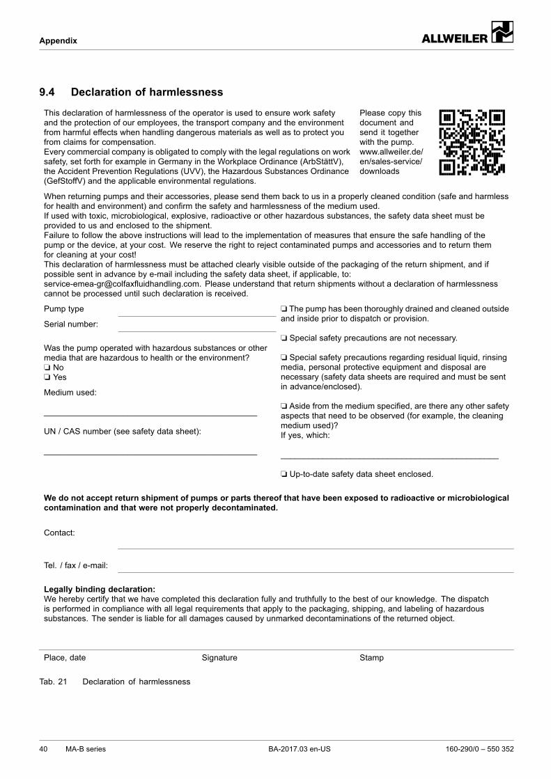
9.4 Declaration of harmlessness
This declaration of harmlessness of the operator is used to ensure work safetyand the protection of our employees, the transport company and the environmentfrom harmful effects when handling dangerous materials as well as to protect youfrom claims for compensation.Every commercial company is obligated to comply with the legal regulations on worksafety, set forth for example in Germany in the Workplace Ordinance (ArbStättV),the Accident Prevention Regulations (UVV), the Hazardous Substances Ordinance(GefStoffV) and the applicable environmental regulations.
Please copy thisdocument andsend it togetherwith the pump.www.allweiler.de/en/sales-service/downloads
When returning pumps and their accessories, please send them back to us in a properly cleaned condition (safe and harmlessfor health and environment) and confirm the safety and harmlessness of the medium used.If used with toxic, microbiological, explosive, radioactive or other hazardous substances, the safety data sheet must beprovided to us and enclosed to the shipment.Failure to follow the above instructions will lead to the implementation of measures that ensure the safe handling of thepump or the device, at your cost. We reserve the right to reject contaminated pumps and accessories and to return themfor cleaning at your cost!This declaration of harmlessness must be attached clearly visible outside of the packaging of the return shipment, and ifpossible sent in advance by e-mail including the safety data sheet, if applicable, to:[email protected]. Please understand that return shipments without a declaration of harmlessnesscannot be processed until such declaration is received.
Pump type
Serial number:
Was the pump operated with hazardous substances or othermedia that are hazardous to health or the environment?❏ No❏ Yes
Medium used:
______________________________________________
UN / CAS number (see safety data sheet):
______________________________________________
❏ The pump has been thoroughly drained and cleaned outsideand inside prior to dispatch or provision.
❏ Special safety precautions are not necessary.
❏ Special safety precautions regarding residual liquid, rinsingmedia, personal protective equipment and disposal arenecessary (safety data sheets are required and must be sentin advance/enclosed).
❏ Aside from the medium specified, are there any other safetyaspects that need to be observed (for example, the cleaningmedium used)?If yes, which:
_______________________________________________
❏ Up-to-date safety data sheet enclosed.
We do not accept return shipment of pumps or parts thereof that have been exposed to radioactive or microbiologicalcontamination and that were not properly decontaminated.
Contact:
Tel. / fax / e-mail:
Legally binding declaration:We hereby certify that we have completed this declaration fully and truthfully to the best of our knowledge. The dispatchis performed in compliance with all legal requirements that apply to the packaging, shipping, and labeling of hazardoussubstances. The sender is liable for all damages caused by unmarked decontaminations of the returned object.
Place, date Signature Stamp
Tab. 21 Declaration of harmlessness
40 MA-B series BA-2017.03 en-US 160-290/0 – 550 352
Appendix
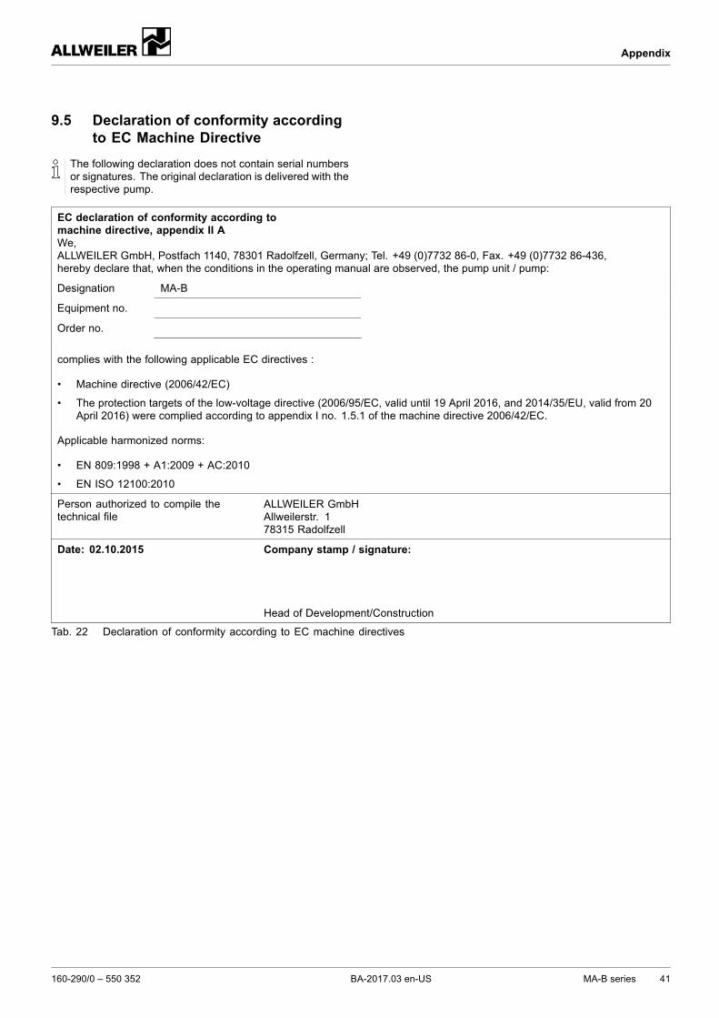
9.5 Declaration of conformity accordingto EC Machine Directive
The following declaration does not contain serial numbersor signatures. The original declaration is delivered with therespective pump.
EC declaration of conformity according tomachine directive, appendix II AWe,ALLWEILER GmbH, Postfach 1140, 78301 Radolfzell, Germany; Tel. +49 (0)7732 86-0, Fax. +49 (0)7732 86-436,hereby declare that, when the conditions in the operating manual are observed, the pump unit / pump:
Designation MA-B
Equipment no.
Order no.
complies with the following applicable EC directives :
• Machine directive (2006/42/EC)
• The protection targets of the low-voltage directive (2006/95/EC, valid until 19 April 2016, and 2014/35/EU, valid from 20April 2016) were complied according to appendix I no. 1.5.1 of the machine directive 2006/42/EC.
Applicable harmonized norms:
• EN 809:1998 + A1:2009 + AC:2010
• EN ISO 12100:2010
Person authorized to compile thetechnical file
ALLWEILER GmbHAllweilerstr. 178315 Radolfzell
Date: 02.10.2015 Company stamp / signature:
Head of Development/Construction
Tab. 22 Declaration of conformity according to EC machine directives
160-290/0 – 550 352 BA-2017.03 en-US MA-B series 41

Appendix
42 MA-B series BA-2017.03 en-US 160-290/0 – 550 352
Appendix
160-290/0 – 550 352 BA-2017.03 en-US MA-B series 43

Appendix
44 MA-B series BA-2017.03 en-US 160-290/0 – 550 352