Embed Size (px)
DESCRIPTION
http://www.energyfromthorium.com/pdf/ORNL-TM-0128.pdf
Citation preview
. . * -
LEGAL NOTICE
This report was preparod as on account of mm*nt sponsor*d work. N0ith.r the United States.
nor the Commission, nor any person acting on boholf of the Commission: A. Makos any warranty or npresontation, orpressed or impliod, wi th r o s p c t to tho accuracy,
complotonoss, or usefulnos. of the information contained in this (.port, or that tho us. of any information, apparatus! method, or process disclosod in this report mor not inking.
privately owned rights; M
6. Assumes any l iabil i t ies wi th respoct to tho us. of, M for damages rosulting from tho use of any informatioh, apparatus, method. or procoss disclosmd in this roport.
As usod in the above, "person acting on bohalf of tho Commission" includes any omployeo or contractor of the Commission, or employoe of such contractor, to tho oxtent that such omployee
or contractor of the Commission, or rmployeo of such eontractor prmporos, disseminates, or
provides access to, any information pur to h is omploym-nt or contract with the Commission,
or h is employment wi th such contractor.
ORNL-TM-128
C o n t r a c t No. W-7405-eng-26
R e a c t o r D i v i s i o n
DEvEL0F"T OF FREZZE V l W E FOR USE IN THE MSRF,
M. R i c h a r d s o n
DATE ISSUED
FEB 2 8 1962
- OAK RIDGE NATIONAL LABORATORY Oak R i d g e , Tennessee
operated by UNION CARBIDE CORF'OFW!ION
fo r t he U. S. ATOMIC ENERGY COMMISSION
i
ABSTRACT
- -
Three types of frozen-seal "valves" w e r e tes ted fo r possible use i n
the MSRE. The seal was melted by direct resistance heat, by induction
heat, and by clamp-on Calrod heat. The frozen sea l was made i n a pre-
formed res t r ic t ion section of a standard piece of pipe by a cooling-gas
je t stream directed a t the restriction. fac tor i ly through 100 test cycles. The Calrod-heated valve was selected
fo r MSRE use on the basis of simplicity of design and of operation. Two
of the valves are successfully undergoing further t e s t s on the MSRE
Engineering Tes t Loop.
All three valves performed satis-
- . 3
INTRODUCTION
A t the beginning of the Molten Sa l t Reactor Program a proven, reliable,
mechanical valve was not available; moreover, it was decided that a develop-
ment program for such a valve would not be undertaken a t tha t t i m e .
experience indicated some success with a freeze-plug type "valve," and a
short evaluation program was ini t ia ted.
tes t stands by using reactor-quality salt a t 1100 t o 120O0F, and a l l three
types proved satisfactory for holding pressures up t o 60 psig. Each valve
was frozen and melted 100 times. There were no e lec t r ica l or mechanical
failures.
incorporated i n the Engineering T e s t Loop i n Building 9201-3.
Past
Three types were tested i n valve
Additional experience was gained through operation of the valves
TEST EQUIPMENT
Two test stands were b u i l t which were identical except for the valve
bodies and auxiliary heating equipment for each valve.
one test system w i l l apply t o both.
A description of
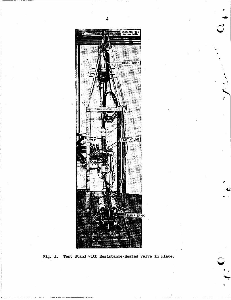
Figure 1 shows that the system (including the valve) was vert ical ly The sump tank was mounted.
made of 6-in. sched-40 Inconel pipe and had a volume of 2.2 gal. A 3/8-in.
sched-40 Inconel pipe connected the suxq tank t o the 1-1/2-in. INOR-8 valve body by means of a 3/8- t o 1-1/2-in. INOR-8 b e l l reducer. from the valve body t o the head t a n k was by similar means.
was made of 6-in. sched-40 INOR-8; the volume of t h i s tank was also
2.2 gal.
The t o t a l volume of the system was 5.6 gal.
The connection The head t ank
Salt-level indicators were of the contact probe type and signaled by
means of control-panel-mounted l ights.
The molten salt was
of gas pressure. Helium was
atmosphere blanket for the
station was provided f o r t h
phere through a CWS f i l t e r .
the lower t o the upper tank by means r t h i s purpose and t o provide an iner t -
suitable gas regulating and venting
e. The system was vented t o the atmos-
1
P Y
I
I
P
5
i i 3.
1 .
Variac-controlled beat was applied t o the tanks and piping by means
of Calrod and clamshell heaters. t o l2OO0F i n the system was 4.5 kw.
Average power required t o maintain 1100
Coolant used for the freeze cycle was plant air or fan-forced room "he freezing tem- air blown across the area of the valve t o be frozen.
perature of the salt was 800 t o 85OoF as measured by externally attached thermocouples located 1-1/2-in. above and 1-1/2-in. below the center of
the valve.
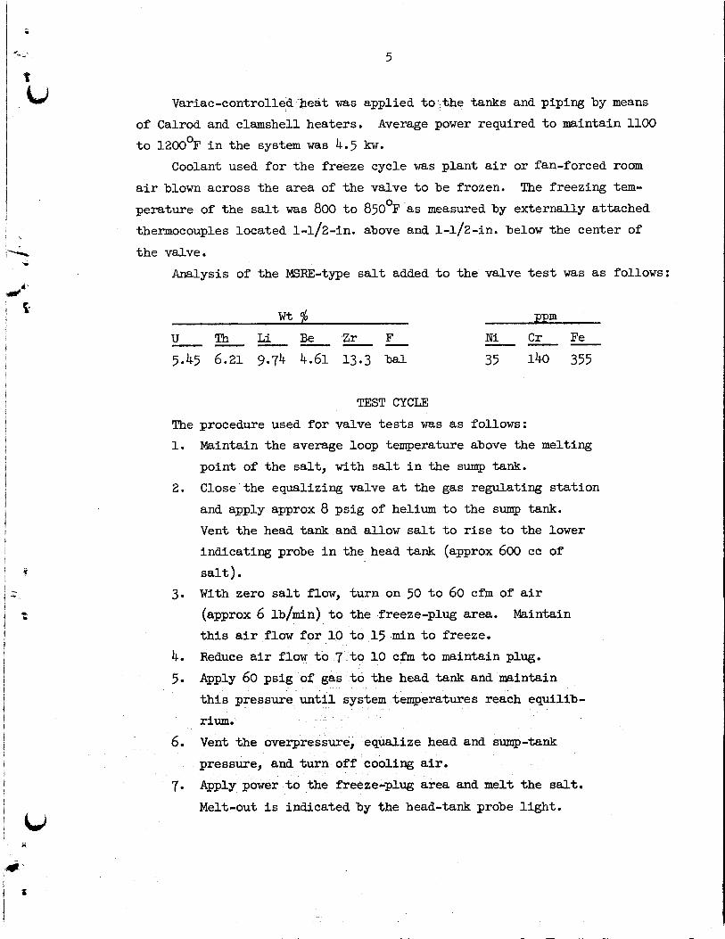
Analysis of the MSRE-type salt added t o the valve test was as follows:
w t $l ppm
N i C r Fe --- U Th L i Be Z r F ------ 5.45 6.21 9.74 4.61 13.3 ba l 35 140 355
TEST CYCLE
The procedure used for valve tests was as follows: 1. Maintain the average loop temperature above the melting
point of the salt, w i t h salt i n the sump tank.
Close'the equalizing valve a t the gas regulating s ta t ion
and apply approx 8 psig of helium t o the sump tank. Vent the head tank and allow salt t o r i s e t o the lower indicating probe i n the head tank (approx 600 cc of
salt) . With zero salt flow, turn on 50 t o 60 cf'm of air
(approx 6 lb/min) t o the freeze-plug area. t h i s air flow f o r 10 t o 15 min t o freeze.
Reduce a i r flow t o 7 t o 10 cfm t o maintain plug. Apply 60 psig of gas t o the head tank and maintain
t h i s pressure rium.
2.
3. Maintain
4. 5.
em temperatures reach equilib-
6. Vent the overpressure, equalize head and sump-tank pressure, and turn off cooling air. Apply power t o the freeze-plug area and melt the salt.
Melt-out i s indicated by the head-tank probe l ight . 7.
i
6
8. Turn off heat t o the plug area; allow salt t o run by gravity t o the sump.
9. Repeat cycle.
The s ize of the frozen area of salt was established by controlling the f l a w of coolant and by adjusting the heat applied t o the valve body on each side of the plug.
3 in. long including the t ransi t ion zone.
A posit ive seal appeared t o be a plug approx
DESCRIPTION OF TEST VALVES
Direct-Resistance Valve
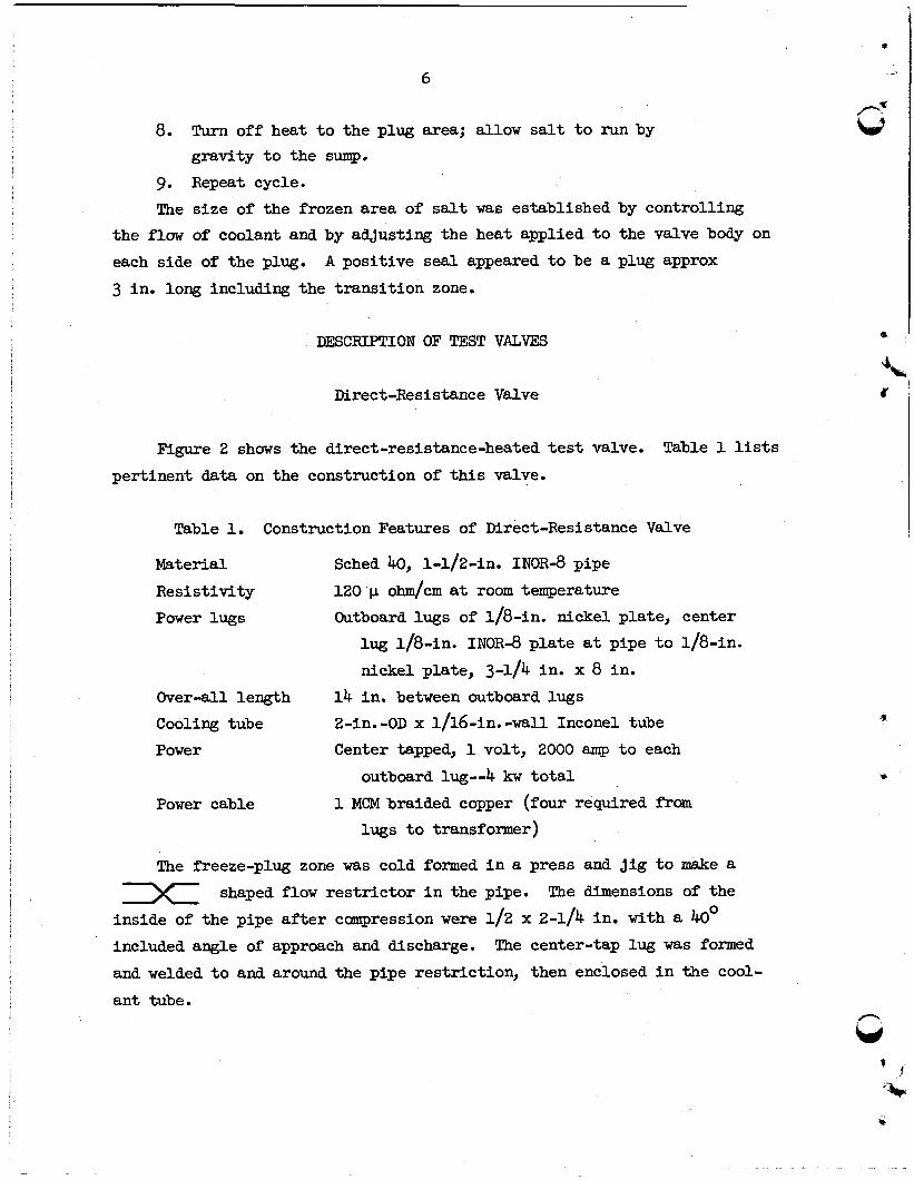
Figure 2 shows the direct-resistance-heated test valve. Table 1 l i s t s pertinent data on the construction of t h i s valve.
Table 1. Construction Features of Direct-Resistance Valve
Material Resistivity
Power lugs
Sched 40, 1-1/2-in. INOR-8 pipe
120 p ohm/cm a t room temperature Outboard lugs of 1/8-in. nickel plate, center
l ug 1/8-in. INOR-8 p l a t e at pipe t o 1/8-in.
nickel plate, 3-1/4 in. x 8 in. 14 in. between outboard lugs 2-in. =OD x 1/16-in. -wall Inconel tube
O v e r 4 1 length Cooling tube Power Center tapped, 1 volt, 2000 amp t o each
outboard lug--4 kw t o t a l
lugs t o transformer) Power cable 1 MCM braided copper (four required from
The freeze-plug zone was cold formed i n a press and jig t o make a The dimensions of the 1 shaped flow re s t r i c to r in the pipe.
inside of the pipe a f t e r compression were 1/2 x 2-1/4 in. with a 40' included angle of approach and discharge.
and welded t o and around the pipe restriction, then enclosed i n the cool-
an t tube.
The center-tap lug was formed
4
r,
7
Fig. 2. Resistance-Heated Valve.
8
Induction-Heated Valve
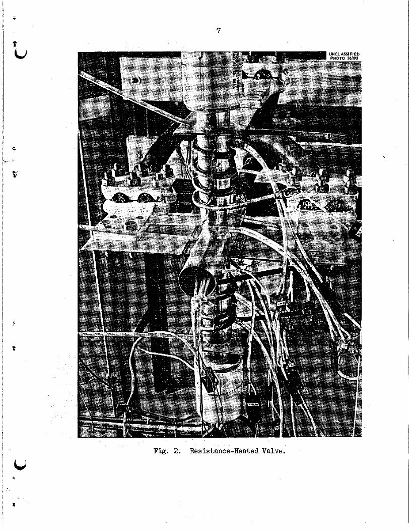
Figure 3 shows the induction-heated valve. Table 2 lists pertinent
data on construction of t h i s valve.
Table 2. Construction Features of Induction-Heated Valve
Material 1-1/2-in. sched-40 INOR-8 pipe
Over-all length 6 in. Power 12-kw, 450-kc spark-gap generator
Power connection 1/4-in. 0.035-in. -wall, copper tube, water
12-turn U-shaped co i l made of 1/4-in. cooled
square copper tubing, spaced 1/16 in.
apart The freeze-plug zone was cold formed t o make a flat, 2 in. long with
The flats were formed on opposite shaped flow res t r ic tor . Inside
Coil
a 20' angle of approach and discharge. sides of the pipe t o make a dimensions were 1/2 in. x 2-1/4 in. x 2 in. long. formed t o permit preferential heating toward the outer edges of the freeze
plug and t o f i t over the 2-in. pipe flat. No par t of the heating c o i l was
attached t o or touching the pipe. and was attached t o the generator by standard brass tubing f i t t i n g s and
1/4-in. copper tube.
required when the generator was i n operation.
The induction co i l was
The co i l occupied 6 in. of pipe length
Water cooling of the generator and heating c o i l was
The freeze plug was formed by directing controlled air flow i n a 1-in.
pipe between the heating co i l s t o each of the f l a t s .
spaced 6 in . from the valve.
employed:
f la t with a 2-in. hose- and high-pressure building a i r piped through a regulator and rotameter t o each of the valve flats with a 1-in. pipe.
The air nozzles were
Two methods of supplying cooling air were
low-pressure air from a centrifugal blower piped t o each valve
I * I
9
Fig. 3. Induction-Heated Valve with Coil in Position.
10
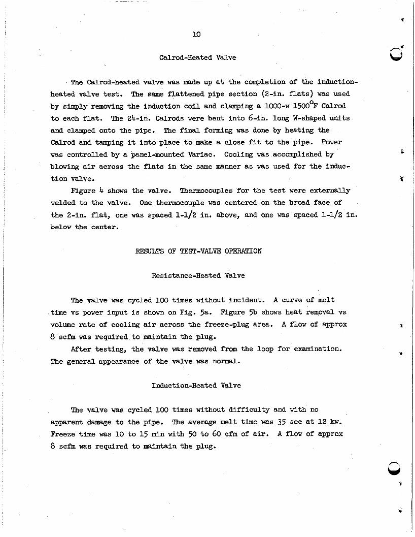
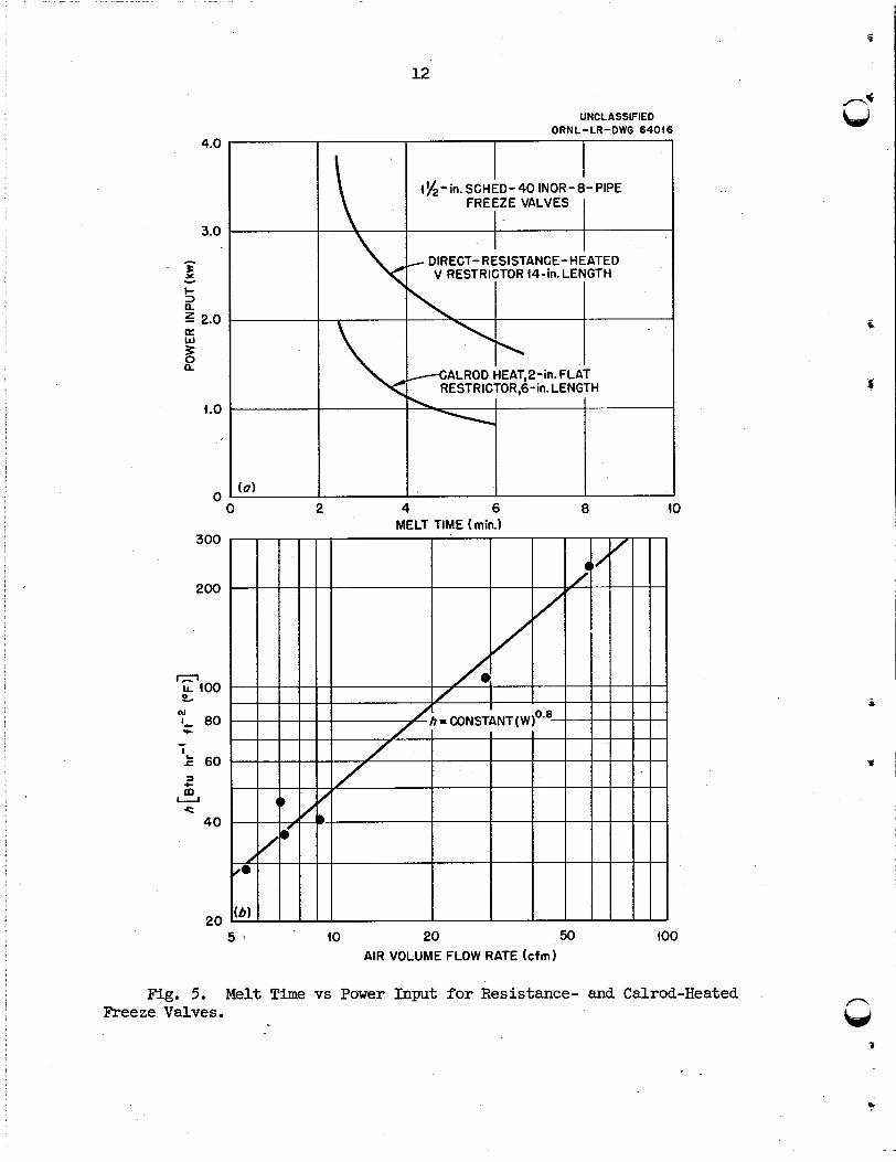
Calrod-Heated Valve
The Calrod-heated valve was made up at the completion of the induction- heated valve t e s t .
by simply removing the induction co i l and clamping a 1000-w 15OOoF Calrod
t o each f l a t . and clamped onto the pipe. Calrod and tampin@; it in to place t o make a close f i t t o the pipe.
The same flattened pipe section (2-in. flats) was used
The 24-in. Calrods were bent i n to 6-in. long W-shaped units The final forming was done by heating the
Power
was controlled by a panel-mounted Variac. blowing air across the flats i n the same manner as was used for the induc-
t i on valve.
Cooling was accomplished by
Figure 4 shows the valve. Thermocouples fo r the t e s t were externally
welded t o the valve.
the 2-in. flat, one was spaced 1-1/2 in. above, and one was spaced 1 4 2 in. b e l o w the center.
One thermocouple was centered on the broad face of
RESULTS OF TEST-VALVE OPERATION
Resistance-Heated Valve
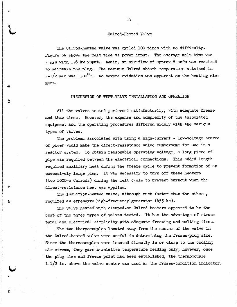
The valve was cycled 100 times without incident. A curve of melt
time vs power input i s shown on Fig. 523. volume ra t e of cooling air across the freeze-plug area.
8 scfm was required t o maintain the plug.
Figure 5b shows heat removal vs
A flow of approx
After testing, the valve was removed from the loop fo r examination.
The general appearance of the valve was normal.
Induction-Heated Valve
The valve was cycled 100 times without d i f f icu l ty and with no
apparent damage t o the pipe. Freeze time was 10 t o 15 min with 50 t o 60 cfm of air. 8 scfm was required t o maintain the plug.
The average melt time was 35 sec a t 1 2 kw. A flow of approx
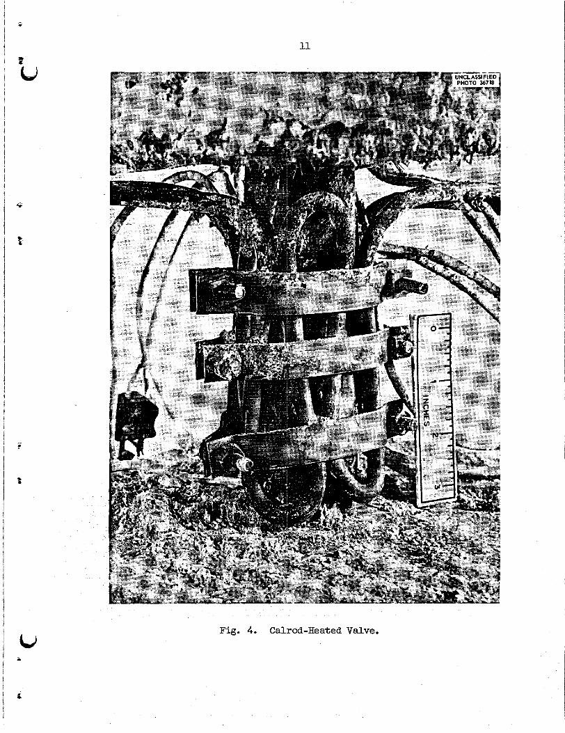
Fig. 4. Calrod-Heated Valve.
UNCLASSIFIED ORN L -LR-DWG 6401 6
I 4g-in. SCHED-40 INOR-8-PIPE
FREEZE VALVES
- DIRECT- RESISTANCE- HEATED V RESTRICTOR 4447. LENGTH
/GALROD HEAT,2-in. FLAT RESTRICTOR,G-in. LENGTH
0 0 2 4 6 8
MELT TIME (min.) 300
200
rn LL 400 %
I- 80
k 60
w
c - I
3
I c t
40
20 5 ' (0 20 50
AIR VOLUME FLOW RATE (cfm)
Fig. 5. Melt Time vs Power Input for Resistance- and Calrod-Heated Freeze Valves.
f
13
Calrod-Heated Valve
The Calrod-heated valve was cycled 100 times with no difficulty.
Figure 5a shows the melt time vs power input.
3 min with 1.6 k w input. t o maintain the plug.
3-1/2 min was 13OOOF.
ment.
The average m e l t time was
Again, an air flow of approx 8 scfm was required
The maximum Calrod sheath temperature attained i n
No severe oxidation was apparent on the heating ele-
DISCUSSION OF TEST-VALVE INSTALLATION AND OPERATION
A l l the valves tes ted performed satisfactorily, with adequate freeze and thaw times. equipment and the operating procedures differed widely with the various
types of valves.
However, the expense and complexity of the associated
The problems associated with using a high-current - low-voltage source of power would make the direct-resistance valve cumbersome fo r use i n a reactor system.
pipe was required between the e lec t r ica l connections.
required auxiliary heat during the freeze cycle t o prevent formation of an
excessively large plug.
(two 1000-w Calrods) during the melt cycle t o prevent burnout when the
direct-resistance heat was applied.
required an expensive high-frequency generator (455 kc).
To obtain reasonable operating voltage, a long piece of
This added length
It was necessary t o turn off these heaters
The induction-heated valve, although much faster than the others,
The valve heated with clamped-on Calrod heaters appeared t o be the
best of the three types of valves tested. It has the advantage of struc- tural and e lec t r ica l simplicity with adequate freezing and melting times.
The two thermocouples located away from the center of the valve i n the Calrod-heated valve were useful i n determining the frozen-plug size. Since the thermocouples were located direct ly i n or close t o the cooling
a i r stream, they gave a relative temperature reading only; however, once the plug s ize and freeze point had been established, the thermocouple 1-1/2 in. above the valve center was used as the frozen-condition indicator.
14
The use of a low-pressure centrifugal blower t o supply cooling a i r was abandoned due t o the control d i f f icu l t ies . The low available pressure
drop prohibited res t r ic t ion of the flow without a damper control mechanism
and required large air leads t o the valve. Proper sizing of a blower with
a variable-speed motor control and an air-volume meter would have permitted satisfactory operation. However, i n the absence of t h i s control the frozen
plug was too large t o permit reasonable m e l t times.
The use of high-pressure building air through standard controls per- mitted very close control of the valve operation as w e l l as the use of much smaller air tubes t o the valve flats. air tube during the test.
tubing was indicated. ducts has the advantages of simplifying the control problem t o a great
extent and reducing the o v e r 4 1 s ize of the valve assembly.
One-inch pipe was used fo r the However, the use of smaller (approx 1/2=in.)
A n air supply which permits the use of small air
DESCRIPTION OF VALVE I N S T M U T I O N I N E ~ I N E E R I N G TEST LOOP
The Calrod-heated valve was selected f o r use i n the MSRE on the basis
of the previously described work and was incorporated in to the hot-salt
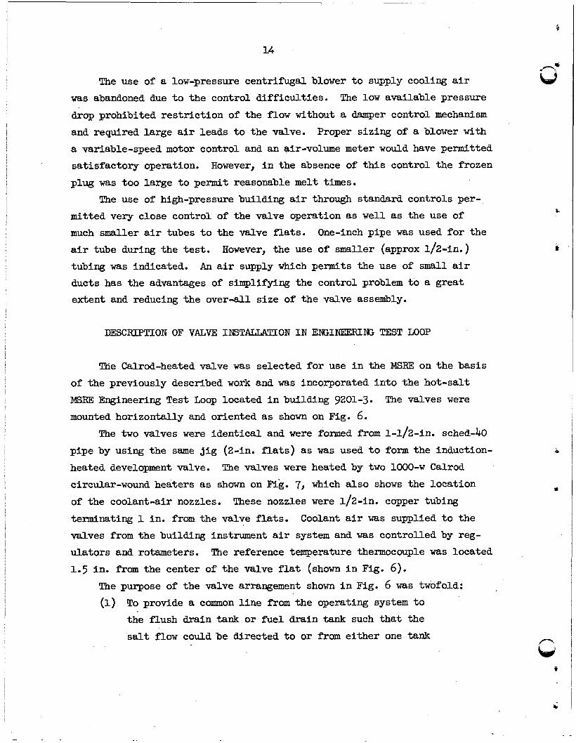
MSRE Engineering T e s t Loop located i n building 9201-3. The valves were mounted horizontally and oriented as shown on Fig. 6.
The two valves were identical and were formed from 1-1/2-in. sched-40
pipe by using the same j i g (2-in. flats) as was used t o form the induction-
heated development valve.
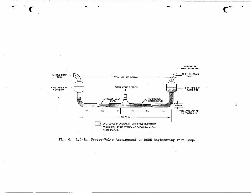
circular-wound heaters as shown on Fig. 7, which a l so shows the location
of the coolant-air nozzles.
terminating 1 in. from the valve flats. valves from the building instrument air system and was controlled by reg-
ulators and rotameters.
1.5 in. from the center of the valve f la t (shown i n Fig. 6).
The valves were heated by two 1OOO-w Calrod
These nozzles were 1/2-in. copper tubing
Coolant air was supplied t o the
The reference temperature thermocouple was located
The purpose of the valve arrangement shown i n Fig. 6 was twofold:
(1) To provide a common l ine from the operating system t o
the flush drain tank or fue l drain tank such tha t the
salt flow couldbe directed t o or Srom e i ther one tank
w r
UNCLASSIFIED ORNL-LR-DWQ 64017
Fig.
4-in. PIPE CAP 4-in. PIPE CAP SURGE POT SURGE POT
HORIZONTAL LEG
3ft in.
@ SALT LEVEL IN VALVES AFTER FORCED BLOWDOWN FROM CIRCULATING SYSTEM AS SHOWN BY X-RAY PHOTOGRAPHS.
6. 1.5-in. Freeze-Valve Arrangement on MSRE Engineering Test Loop,
16
m al rl N
N
a" rl 0 0
u
?3 k 4 a u 8
s f R s
d
Fr
G P
17
or the other. One valve or the other w i l l be frozen
a t a l l times depending upon the operation.
To ensure that sufficient salt would remain i n the
valve t o make a positive frozen seal under a l l con-
ditions.
(2)
The volume of the operating system i s such that, when salt i s moved
from either of the drain tanks t o the operating system, there will always
be salt i n the valves t o make a seal.
between the valves and the drain tanks make it impossible t o completely
empty the valves when draining the circulating system in to the tanks. surge-pot volumes are such that there i s sufficient residual salt i n the
valve body t o form a seal. The valve bodies would drain completely were
it not for these pots.
The surge pots shown i n Fig. 5a
The
--VALVE OPERATION AND FG3SULTS I N THl3 ENGINEERING TEST LOOP
The valve t o the flush tank i n the Engineering Test Loop was operated with coolant salt (LiF-BeF2, 66-34 mole $) through 40 cycles without diffi-
culty.
fa i l t o open the l ine, but indications are tha t the diff icul ty was a plug
i n the l i n e upstream from the valve.
adjacent valve, which had seen the same operation conditions, operated
After approx 1300 h r of operation the initial melt appeared t o
Once the drain l i n e was clear the
normally.
0.5 lb/min) a i r flow.
3.5 scfm (approx 0.3 lb/min).
salt flow i n the pipe i n a l l cases.
reference temperature was approx 3 in.
The average freeze t i m e was 7.5 min and required 6 t o 7 scfm (apsrox
Air flow required t o maintain the plug was approx
The freeze cycle was accomplished with zero
The frozen-plug length a t 70O0F
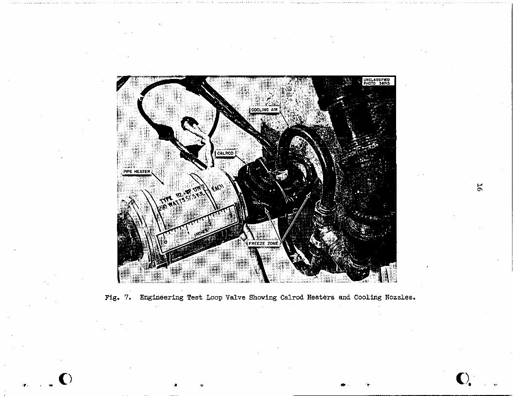
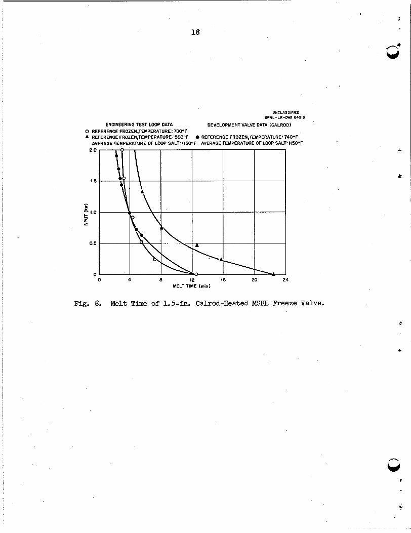
The melting time vs power input curves fo r ' t h i s valve are shown on
The difference i n melt times between the 500 and 70O0F steady- Fig. 8. state reference temperatures shows clearly the effect of the frozen-plug
size. An operational tes t was performed on the Engineering Test Loop t o check
the operation of the valves under a forced-drain condition. The valve t o 11J i
!
18
UNCLASSIFIED ORNL-LR-DWO 64016
ENGINEERING TEST LOOP DATA DEVELOPMENT VALVE DATA (GALROD) 0 REFERENCE FROZEN,TEMPERATURE: 7 W o F A REFERENCE FROZEN,TEMPERATURE: 5W°F 0 REFERENCE FROZEN,TEMPERATURE: 74OOF
AVERAGE TEMPERATURE OF LOOP SALT: 415OOF AVERAGE TEMPERATURE OF LOOP SALT:I45O0F 2.0 L -
c)
L 4.5 .
- s 5 4.0 s n z
0.5
0 0 4 8 42 46 20 2 4
MELT TIME (min)
Fig. 8. Melt Time of 1.5-in. Calrod-Heated MSflF, Freeze Valve.
.
19
i . )
i * i
I - > *
the fue l drain tank remained frozen while the flush-drain tank valve was
melted.
force the salt i n to the flush-drain tank through the valve. Gas flow was
permitted t o continue through the valve a t the completion of the draining operation a t a rate of 2.2 scfm helium.
the gas pressures were equalized between the drain tank and the pump, the
valve was frozen, and x-ray photographs were taken of the valve assembly.
The photographs indicated tha t suff ic ient s a l t remained i n the valves t o
form a seal (Fig. 6). was reapplied.
Five psig of helium was impressed on the circulating system t o
The gas flow was then shut off,
The valve proved t o be leak-tight when gas pressure
DISCUSSION OF VALVE OPERATION I N THE EWINEERIW TEST LOOP
Operation of the valves has been satisfactory, with the exception of the one blockage tha t i s believed t o have been due t o a plug i n the upstream l i n e and not due t o the valve design or operation.
The lower cooling-air requirement fo r these valves compared with the
e a r l i e r valves i s at t r ibuted t o the a i r nozzle being only 1 in. away from
the valve f lat and t o the be t t e r air flow t o the f lat tha t i s permitted by
the open-center winding of the Calrods. The surge pots appear t o be ade- quate t o prevent the valve from being blown empty during a forced dump.
The equalization of gas pressures during freezing i s an important opera-
t iona l procedure f o r two reasons: the valve i s d i f f i cu l t t o freeze with a q movement of salt due t o differences i n gas pressure, and reverse gas
flow j u s t before freezing could possibly leave a gas pocket i n the valve with salt on each side.
CONCLUSIONS AND RECOMMENDATIONS
The Calrod-heated valve i s recammended because of i t s s t ructural sim- p l i c i t y and the simplicity of the associated power and control equipment.
The Calrod un i t should b
than the W-shaped uni ts as were used f o r the develupment valve.
t o avoid short-radius bends and t o provide be t te r air flow.
l l e d i n a t i g h t co i l as shown i n Fig. 7 rather
This i s
A single uni t
20
i
horseshoed" around the f la t i n a manner similar t o the induction c o i l I?
shown on Fig. 3 would be desirable.
leads and make an easi ly removable unit.
This would reduce the nmiber of power
cooling air requirements w i l l depend-on c e l l temperature and cooling a high rate t o make the a i r temperature.
i n i t i a l freeze and a low rate t o hold the freeze.
Two volume rates are required:
The holding flow rate controls the plug s ize and must be selected and
kept steady t o prevent a meltout from heat leakage due t o insufficient
cooling.
cessive meltout time.
i n the f ie ld since it i s dependent on c e l l and cooling air temperatures.
Too much cooling w i l l result i n a large plug and consequent ex-
The holding flow ra t e should preferably be determined
Surge pots having a r a t i o of ver t ica l l eg volume t o the volume of the
horizontal valve and pipe section of 2, as shown i n Fig. 5a, should be in-
stalled t o prevent the valves from being blown empty. For a given system, operating procedures must be analyzed t o determine the location of these
pots. The use of high-pressure compressed air, rather khan low-pressure
blower-supplied air, fo r cooling i s recommended because of easier control,
smaller ducts, and smaller over-all s ize of the valve assembly.
Recommended freeze-valve controls are: 1. Manual control of power t o Calrods and manual air-flow
control. Interlock t o prevent heat and cooling air from being
applied a t the same time. 2.
3. Once the freeze temperature has been established, the
center thermocouple should be interlocked t o switch automatically from high- t o low-volume a i r flow.
A high-temperature (l5OO%) cutout or alarm located
on the Calrod sheath.
An interlock between a liquid-level probe and the
valve parer input t o prevent prolonged heating of
the C a l r o d .
salt i s flowing, f i r t h e r heat i s not needed.
4.
5.
Once the m e l t i s accomplished and the
21
6. For a meltout, a single control t o close off cooling air and apply power t o the valve a t a preset rate.
There must be no salt flow through the valve, o r a freeze cannot be
accanrplished.
A ACKNOWLEDGMENT
The author i s indebted t o many members of the Molten Salt Reactor
Program fo r their contributions t o this report. Special. acknowledgment i s due D. Scott, J. C. Moyers, and J. L. Crowley f o r t h e i r advice and sugges-
tions.
The direct-resistance valve was designed by J. L. Crowley; the Calrod
and induction-heated valve design was based on the field work done by the
many predecessors i n the molten-salt f ie ld .
The author wishes t o express h i s appreciation t o J. L. Crowley and
W. H. Duckworth f o r t he i r contribution in the testing of the valves.
BIBLIOGRAPHY
MSR Quart. Progr. Rept. July 31, 1961, ORNL-3014, p 25. MSR Quart. Progr. Rept. July 1, 1960, ORNL-3lZ2, p 27.
:-
I
4
f
23
ORNL-TM-128
1. G. M. Adamson 42. L. G. Alexander 3. S. E. B e a l l 4. M. Bender 5. C. E. B e t t i s 6. E. S. B e t t i s 7. D. S. B i l l i n g t o n 8. F. F. B l a n k e n s h i p 9. A. L. B o c h
10. E. G. B o h l m a n n 11. S. E. B o l t 12. C. J. B o r k o w s k i 13. C. A. Brandon 14. R. B. B r i g g s 15. F. R. B r u c e 16. 0. W. Burke 17. T. E. C o l e 18. J. A. C o n l i n 19. W. H. C o o k 20. G. A. C r i s t y 21. J. L. C r o w l e y 22. F. L. Culler 23. J. H. DeVan 24. F. A. Doss 25. D. A. Douglas 26. N. E. Dunwoody 27. E. P. Epler 28. W. K. Ergen 29. D. E. Ferguson 30. A. P. Fraas 31. J. H. Frye 32. C. H. G a b b a r d 33. R. B. G a l l a h e r 34. B. L. G r e e n s t r e e t 35. W. R. G r i m e s 36. A. G. G r i n d e l l 37. R. H. Guymon 38. P. H. H a r l e y 39. C. S. H a r r i l l 40. P. N. H a u b e n r e i c h 41. E. C. R i s e 42. H. W. H o f f m a n 43. P. P. H o l z 44. L. N. H o w e l l 45. J. P. Jarvis
Internal D i s t r i b u t i o n
46. W. H. Jordan 47. P. R. Kasten 48. R. J. K e d l 49. G. W. K e i l h o l t z 50. S. S. K i r s l i s 51. J. W. m e w s o n 52. J. A. Lane 53. W. J. Leonard 54. R. B. Lindauer 55. M. I. Lundin 56. R. N. Lyon 57. H. G. MacPherson 58. F. C. Maienschein 59. W. D. Manly 60. E. R. Mann 61. W. B. McDonald 62. H. F. McDuffie 63. C. K. M c G l o t h l a n 64. A. J. Miller 65. E. C. Miller 66. R. L. Moore 67. J. C. Moyers 68. C. W. N e s t o r 69. T. E. Northup 70. W. R. O s b o r n 71. L. F. Parsly 72. P. Patriarca 73. H. R. Payne 74. A. M. Perry 75. W. B. Pike 76. J. L. R e d f o r d 77. M. R i c h a r d s o n 78. R. C. R o b e r t s o n 79. T. K. R o c h e 80. M. W. R o s e n t h a l 81. H. W. Savage 82. A. W. Savolainen 83. D. Scott 84. M. J. Skinner 85. G. M. Slaughter 86. A. N. S m i t h 87. P. G. S m i t h 88. I. Spiewak 89. B. Squires 90. J. A. Swartout
91. A. 92. J. 93. R. 94. D. 95. w. 96. B. 97. B. 98. A. 99. J.
Toboada R. Tallackson E. Thoma B. Trauger C. Ulrich S. Weaver H. Webster M, Weinberg H. Westsik
24
100. 101. 102.
103-104. 105-106. 107-109. l l0- l l2 .
113.
L. V. Wilson C. E. Winters C. H. Wodtke Reactor Division Library Central Research Library Document Reference Library Laboratory Records Laboratory Records (LRD-RC)
External Distribution
114-128.
130-131. Reactor Division, OR0
Division of Technical Information Extension ( JrrIE) 129. Research and Development Division, OR0
? .