Embed Size (px)
DESCRIPTION
http://www.energyfromthorium.com/pdf/ORNL-TM-1859.pdf
Citation preview

OAK RID~GE NATIONAL LABORATORY
: operated by
UNION CARBIDE CORPORATION . .I tar tne
Y U.S.mAIOMIC ENERGY COMMISSION c*
ORNL- TM- 18%
COPY NO, - 23% ’
DATE - 6/30/67
MAINTENANCE DEVELOPMENTFOR MOLTEN-SALT BREEDER REACTORS
~mm Robert Blumberg
.ABSTRACT
The maintenance.system of the proposed molten-salt breeder reactors will be based upon the technology in.use and experience gained
L 7 from the Molten-Salt ReactorExperiment.- The unit replacement scheme, -j long-handled-tools, movable maintenance shields,and the means for i handling contaminated equipment will..be-similar..for manyoperations. I The techniques must be improved and extended.and-new techniques must d i be developed for maintaining--some of-the-larger more radioactive ! components.of the breeder reactors.. Remote welding-is needed for i major component replacement,- Methods-must be:.available for replacing I the core and for the repair.of heat exchangers. ,Finally, a,general t development.and design surveillance program-:.wiU..be,required.~ These ‘ Dromams are described and their..cost is estimated.
fhis document contains inf&motion of a preliminary nature and was prepared primarily for internal use at the Ook Ridge National Laboratory.’ It is sub eh’,’ to revision or correction ond therefore does not represent a final report. f information 1s not to bem~obstrocted, reprinted or otherwise given public dis- semination without the approval of the ORNL potent branch, Legal and infor- motion Control Department.

LEGAL NOTICE
This report was prepared as an account of Government sponsored work. Neither the United States,
nor tho Commission, nor any person acting on behalf of the Commission: A. Makes any warranty or npresentation, expressed w implied, with r e s p c t to the occuracy,
completeness, or usefulness of the information contained in this report, or that the us* of
any information, apparatus, method, or process disclosed in this report may not infringe privately owned rights; or
any information, opporatus, method. or process disclosed in this report. B. Assumes any l iabil i t ies wi th respect $0 the use of, or for damoges resulting from the use o f '
As used in the above, "person acting on behalf of the Commission" includes any employee or contractor of the Commission, or employee of such contractor. to the extent that such employee
or contractor of the Commission, or employee of such contmctor pnpans, disseminates, or
provides access to, any informotion pursuant to h is employment or contract wi th the Commission,
or his employment with such contractor.
INTRODUCTION
iii
TABLE OF CONTENTS Page
1
PHILOSOPHY OF MAINTENANCE
DESCRIPTION OF PRESENT TECHNOLOGY
MSRE MAINTENANCE EXPERIENCE AS R E W E D TO MOLTEN-SALT BREEDER REACTORS
DISCUSSION OF ANTICIPATED PROBLEMS
Piping Connections and Vessel Closures
Replacement and Repair of Components
Large Component Replacement
Core Replacement
Heat Exchanger Replacement
Repair of Components
Radioactive Component Examination
Improved Performance
INCREASED RADIATION LEVEL
GENERAL MAINTENANCE DEVELOPMENT AND DESIGN SURVEILLANCE
PROGRAM COSTS AND SCHEDULE
1
2
4
5
5
7
8
8
9
9
10
10
11
11
13


/
INTRODUCTION
One of the basic differences between a molten-salt reactor o r any circulating-fuel reactor and the more widely u t i l i zed , so l id or stationary fuel reactor, i s i n how each contains f iss ion products. important ramifications o f t h i s difference i s i n the area of maintenance. The circulat ing f'uel deposits some f i ss ion products i n the reactor system, drain tanks, offgas system, and the fue l processing system. natural ly a r i se . From our experience with Homogeneous Reactor Experiment-2 (HIIE-2 or HRT) and the Molten-Salt Reactor Experiment (MSIIE) , t he answer is an unquali- f ied yes. Another question is , "Are such systems much more expensive t o maintain than so l id me1 systems?" assessed because of the complexity of the economics, but when one accounts for the costs involved with replacing spent fuel elements, the answer i s no longer c lear ly i n favor of the so l id f'uel system. cheaper t o maintain a circulat ing fuel reactor.
breeder reactor (MSBR) is described i n 0 ~ ~ ~ 3 9 9 6 . ~ developing the breeder through a molten-salt breeder experiment ( MSBE) i s summarized i n ORNL-TM- 18%. of development of methods and equipment for maintaining t h e radioactive equipment of t he MSBE. scaleup o f t h e equipment should be necessary t o sa t i s f ac to r i ly maintain the la rger MSBR.
One of the
Questions Is it feasible t o maintain such radioactive systems?
This question cannot be adequately
It may well be
A reference conceptual design fo r a 1000-Mw(e) molten-salt thermal The program for
The following report describes a program
A major c r i te r ion fo r the program i s tha t only
PHILOSOPHY OF MAINTENANCE
The prime philosophy of maintenance of fa i led radioactive components i n molten-salt breeder reactors is simply stated as remove, replace and repair o r discard. We do not plan t o repair those components i n place. They w i l l be removed and replaced by a new o r repaired unit and then w i l l
the s i ze and cost of the uni the value of the repaired un appears t o be the best way o back i n t o operation.
I be repaired i n specially equipped f a c i l i t i e s o r discarded depending on i f f i c u l t y of making the repair , and
h i s philosophy was adopted because it ng repairs quickly t o get the plant
One of the mgst import philosophy i s t h e ' e f f o r t t o are infrequent -and discard not prohibit ively expensive. engineering development w i l l place emph'asis on establishing a predictable and prac t ica l l i f e fo r t he components permitting us t o es tabl ish a philosophy which includes discard of the f a i l ed component i f it is too radioactive fo r d i rec t o r semi-direct maintenance.
s which af fec ts t h i s maintenance components reliable so repairs
The program fo r
Emphasis a l so w i l l be on rapid replacement t o educe the down time f o r the system.
The reactor vessel , the heat exchangers fo r the f'uel and blanket systems, the drain tanks, and the pump rotary elements w i l l become so radioactive tha t they w i l l normally be discarded. It may be necessary

2
t o disassemble and examine a f a i l ed component t o determine the exact cause of fa i lure but t h i s would not require tha t t he component be re- assembled. Possibly the fa i led component w i l l be stored i n the same c e l l with the reactor t o a w a i t some decay before examination.
The offgas system and the chemical process plant w i l l contain many Where pract ical , of the f iss ion products and w i l l be very radioactive.
components of these systems w i l l be decontaminated and repaired w i t h a minimum of shielding, otherwise they w i l l be discarded and a new component w i l l be installed.
~
The coolant system ordinarily should not be very radioactive. There is some activation of the sodium but with the system drained the residual ac t iv i ty should be low enough t o permit direct maintenance. The pres- sures in t h i s system are maintained above the opposing pressures across the tube w a l l s i n the fue l and blanket heat exchangers so t ha t any leakage would be out of the coolant system. tamination of the coolant salt with f iss ion products. f iss ion products should get in to the coolant system, then some decontamina- t i on would be necessary before maintenance would be possible.
The steam and turbine generator system should never become radioactive
Thi.s arrangement should prevent con- If perchance
since it is separated fromthe prime sources of ac t iv i ty by the coolant system and from direct neutron activation by the shielding o f t h e c e l l w a l l s . Conventional methods of direct maintenance w i l l be used here.
In t h i s program w e s h a l l concentrate on developing the techniques for maintainingthe highly radioactive components such as t he core, pump, drain tanks, and heat exchangers.
DESCRIPTION OF PRESENT TECHNOLOGY
The present s ta tus o f t h e technology of maintenance of molten-salt reactors is largely embodied i n the maintenance scheme fo r the MSRE. Methods and equipment i n use at the MSRF: are based on extensive experience gained on the aqueous Homogeneous Reactor Experiment No. 2. Experience w i t h remote maintenance of the radiochemical plants at Hanford and Savannah River, repair of the Sodium Reactor Experiment, and remote dis- mantling of various reactor assemblies contributes in a general, and often important way, t o the development.
$0 achieve a pract ical level of maintainability, uniform methods are provided far gaining access t o , removing, and replacing a31 of the equip- ment i n the radioactive areas of the reactor. A t t he MSRF,, t h i s includes the reactor c e l l , the drain tank c e l l , the offgas system and the chemical process system. and replace it with an interchangeable spare. w a s placed i n design and construction phases on making components re l iab le so t ha t the need for replacement i s infrequent-and discarding fa i led com- ponents i s not prohibitively expensive. However, f a c i l i t i e s have been provided for some some decontamination and repair of equipment.
The general philosophy is t o remove a failed component A considerable emphasis

3
Reducedto fundamentals, t he MSRE i s a collection of component par t s which a re capable of being disconnected and reconnected remotely. Access t o these uni t s i s provided through removable shielding sections t h a t make up t h e roofs of t he various ce l l s . s t a l l e d over the component, the roof section i s removed, and long-handled too l s are used t o do the manipulations tha t are required.
t o o l access holes, l ight ing, and maneuverability. a re , for the,most par t , simple, strong, and single purpose. and lead glass windows i n the shield provide viewing i n the work area. A l l preparations fo r removal a re donehcompletely with the portable shield. After la rge components a re prepared f o r removal w i t h the same technique, they are removed from the ins ta l led position by means of a crane operated by personnel inside a shielded control room with closed-circuit te levis ion and l iqu id- f i l l ed windows for viewing. use of sui table transport shields. decontamination c e l l can be reached by the crane so that contaminated equipment can be disposed of conveniently.
A portable maintenance shield i s in-
T h i s port b le shield provides 12 in . of steel for shielding (attenuation factor 10 E -lO5),
The long-handled too ls Periscopes
Small components are removed by A hot-equipment storage c e l l and a
i
The a b i l i t y t o completely disconnect a par t icular component is basic The disconnects must be remotely operable by the long-
They must be re l iab le both f o r the service conditions and t o t h i s system. handled tools . f o r the high radiation and i n some cases must satisfy nuclear safety considerations of containment leak t ightness and leak detectabi l i ty . number of different disconnects a re used at the NSRE for the various applications. Almost a l l t h e piping i n such auxiliary systems as the offgas, lubricat ing o i l , air , and cooling water systems have standard r ing jo in t flanges, with minor modifications. Special designs were used for leak detector tubing, thermocouple, e l ec t r i ca l and instrument leads.
A
The disconnects for the 5-in. sched-40 piping are cal led freeze flanges. They are large diameter, unheated and uninsulated flanges. The clamping device, a U-shaped spring clamp, and the r ing gasket sea l are near the perimeter and operate at a much lmer temperature than the bore of the pipe. The oversize flanges take up much space, have large temperature gradients, and require large clamping forces. ment was required t o obtain t h e desired serviceabi l i ty and maintainability, but f ive pa i r s of flanges are now i n service at the MSRE and they work w e l l . While they have never been broken and remade remotely i n a radia- t i o n field, t h e long-handled too ls which were developed fo r th i s purpose were used f o r the assembly of the reactor and t h e i r operabili ty was established t o that extent.
Much deyelop-
I The drain and st the reactor i s connec d with 1-1/2-in. sched-40 piping. It is p l and brazing these l ines . and has been extensively tes ted i n mockups, but not yet i n a radioactive s i tuat ion.
in ta in t h i s system by remotely cut t ing t o accomplish th i s i s on hand3

1
4 - The maintenance philosophy.in use for most par t s of the WRE is t o
replace a fa i led , contaminated uni t with a spare component. Spares are Cj
w
bu i l t i n j i g s t o assure interchangeability. not too radioactive are par t ly decontaminated and repaired by direct contact with the help of l oca l shielding t o reduce the radiation level. To satisfy the requirements of t he MSRE, a constant. review was made o f t h e component and ins ta l la t ion design t o insure tha t it was maintain-
Pieces tha t are small and
2 I
I
I
able and, where.necessary, mockups were constructed t o a s s i s t ' i n guiding I the designers. I
! -
MSRE MAINTEEJAMCE EXPERIENCE AS RELATED TO MOLTEN-SALT BREEDER REACTORS I
The MSRE has been successfully operated and maintained during the past year and a half. replaced or repaired p d several d i f f i cu l t operations were completed which were unanticipated in our planning for maintenance. To evaluate our ex- perience i n the l i g h t of t he needs of the breeder, one may divide all of the equipment of the ERE i n to two classes. all the large salt-containing vessel and piping complexes. three major components in t he reactor c e l l , t he drain tanks and the interconnecting piping. maintenance jobs, they are a l s o low frequency jobs. maintained these large components. The second c lass includes all of the r e s t of the removable equipment; items such as control rods, heaters, valves, auxiliary l ines , offgas component, e tc . maintenance work w i l l be dane because of the higher failure rate . maintenance capabili ty has been clear ly demonstrated fo r the second class of equipment. knowledge of the magnitude of t he radiation and contamination leve ls , and a first hand knowledge of t he ab i l i t y of the system t o handle unanticipated problems, we make the following statements regarding WRE maintenance.
Several different items of equipment have been
The first class includes These are the
While these complexes have the most d i f f i cu l t We have not yet
This is where most of t he The
Based upon many hours of actual work experience, a detailed
- 1. We believe tha t the demonstration(of maintenance of the major fue l
components (i.e. , t ha t which we have not yet done) i s merely a matter of doing it when the occasion arises. It presumably w i l l be more d i f f i cu l t and w i l l require more t i m e but nevertheless i s w e l l within our capabili ty.
J
?
\i
t
2. The ERE maintenance system possesses several a t t rac t ive qua l i t i es , including r e l i a b i l i t y , simplicity, ruggedness and f lex ib i l i ty .
3. There are two weaknesses of the system which have been recognized, These are the levels of radiation around t o o l penetrations and the method of disposing of contaminated equipment. be improved quite readily through design and procedural changes.
These are weaknesses tha t can
4. The MSRE can continue t o supply information of value t o t he MSBR It is planned t o conduct experiments, perform maintenance tasks program.
and gather data, during the remainder of t he operating l i f e of t he MSRE. Projects of t h i s nature include demonstrating the replacement of a major component, mapping the gamma radiation levels i n a portion of the reactor c e l l and the offgas system, and continuing the plot t ing and analysis of i n -ce l l radiation levels . of the fue l and offgas systems t o a l eve l which would permit direct main- tenance w i l l be investigated.
The poss ib i l i t i es of decontaminating components

5 F
4 7
4
t
a j
5 . We believe t h a t the requirements of the MSBR can best be ful- f i l l e d with a system based generd ly on the one i n use at the MSRE. The equipment must be modified, a f course, t o meet increased require- ments i n performance and i n s i ze , weight and radiation capabi l i t ies . Finally, it must be modified t o re f lec t the specific design problems of the breeder.
DISCUSSION OF ANTICIPATED PROBLEMS
We propose t h a t t h e system for maintaining the radioactive components o f t h e MSBR be based on the technology and experience of the EasRE. The overhead access, movable maintenance shield, separable components and long handled too l s t o accomplish i n c e l l manipulations wil l be retained. We know t h a t some new techniques must be developed and exis t ing techniques must be improved. based upon a more detailed design of t he reactor than now exis ts . The MSBR w i l l be larger . be larger and heavier, so the maintenance equipment must have increased capabi l i t ies . weighs higher, so the shielding must be increased. module is higher by a factor of about 80 and the residual ac t iv i ty a f t e r the fue l salt i s drained would be correspondingly higher. would require some additional thickness in the portable maintenance shield, the important e f fec t w i l l be the at tent ion which m u s t be given t o the cracks around the too ls at penetrations. requirements d ic ta te a compact design for the fue l , blanket, and some auxiliary equipment and systems. f i c u l t . more emphasis on eff ic ient maintenance. of t he places where problems are anticipated, proposed sblutions t o the problems, and the development required. marily w i t h the large breeder reactors. problems but on a smaller scale and the research and development w i l l i n most instances be done on MSBE scale.
However, the de ta i l s of the maintenance system must be
The pumps, heat exchangers, and reactor vessel w i l l
For example, the reactor vessel for a 250 Mw(e) IBBR module Radiation levels w i l l be 71 tons compared t o 9 tons fo r the MSRE.
The power leve l i n an MSBR
While t h i s
Economic factors and some nuclear
This tends t o make maintenance more dif- Finally, economic considerations and program objectives place
The following is a discussion
This discussion i s concerned pr i - The MSBE w i l l have the same
Piping Connections and Vessel Closures
The unit replacement sch closures tha t are highly re l i maintained remotely. main f u e l and blanket rec i rcu l t he offgas system, . the fue l an par t s of the coolant and other radioactive areas. the fue l and the blanket heat exchangers. i n t h e MSRE and ins ta l led i n areas about 400°F, use can be made of e been proven at the ERE. new d i f f i cu l t i e s : (1) The 2b-in.-diam piping i s considerably la rger than has been used with remotely disconnectable jo in ts . (2 ) The 1150'F ambient
equires piping connections and vessel i n service and are capable of being
I n the MSBR these connections w i l l be needed i n the systems, the drain and storage systems, e t processing systems, and i n the ary systems tha t must be located i n
Vessel closures w i l l be needed on the reactor and on For l i nes no la rger than those
e re t h e ambient temperature i s below n t and techniques t h a t w i l l have
However, t he design of the MSBR imposes three

6
temperature proposed for the reactor c e l l i s considerably higher than has been used i n the past . needed for t he MSBR have been developed for remote operation and elevated temperatures.
(3 ) No vessel closures approaching the size
In the reference design of the MSBR, Six connections are required i n the reactor c e l l i n the large l i nes tha t jo in the reactor vessel t o the heat exchangers and the heat exchangers t o the coolant system. welding, we believe, i s the best way t o make sat isfactory jo in ts i n those l ines . Welding also appears t o be the best way of making re l iab le vessel closures and it i s possible t h a t t he design of a vessel closure sea l can be made fundamentally the same as t he piping connection. siderable development w i l l be required, the program seems t o be straight- forward and the goal reasonably attainable. flanges for those l i nes would a l so be d i f f i cu l t and probably would require considerably more long-term test ing. closures, remote welding can be used on the smaller l ines i n all the radioactive systems. en t i re nuclear industry.
Remote
While con-
Development of sat isfactory
Once developed fo r the la rger
The development w i l l be of considerable value t o the
Some development has already been done on remote welding. Atomics
They International Division of North American Aviation, Inc. , h e equipment for remote welding of small tubing for repairing heat exchangers. are deeply involved i n automatic welding development including the join- ing of 4O-ft-long pieces of k-in.-diam pipe for deep-well casings by welding from the i n ~ i d e . ~ point of completing many seal w e l d s and tes t welds on large and small pipes with remotely operated equipment. automatic equipment tha t w i l l make high quality welds on 30-in.-diam pipe. North American Aviation, Inc., has used the "skate welding'' method for fabricating missiles where the welding is controlled from a remote location. 6
\
The PAR Project advanced the technology t o the
The pipeline industry has
The welding development w i l l be a jo in t e f fo r t of t he Materials Development Program and the Maintenance Development Program. consist primarily of:
It w i l l
1. designing and qualifying the weld jo in t s ,
2. supporting the improvement o r modification of exis t ing automatic welding apparatus,
adding the j i g s and fixtures required t o align and hold the pipe o r vessel and the manipulative devices t o operate the torch, and
making tes t welds t o improve the techniques u n t i l good
3.
4. -
welds can be made consistently.
,--- The maintenance development w i l l a l so include the devices for cut t ing the seals and machining the ends t o the specified configuration. design using a sea l weld with a mechanical clamping device t o provide
w a l l members.
bJ A jo in t
t he strength i s a possible alternative t o the multi-pass welding of thick 9

.3 7
Development of techniques fo r inspecting and repairing welds i n radio- ? active areas must accompany the e f for t on remote welding.
via closed c i r cu i t te levis ion and dye penetrant and ultrasonic t e s t ing techniques appear t o be applicable, whereas radiography does not appear feasible. design tha t w i l l allow complete confidence i n the jo in t without t he detailed evidence of a t o t a l l y inspected weld. jo in t is one example of such a design.
Visual inspection ht
An intensive study of the jo in t configuration may reveal a
A leak detectable buffered
One arrangement fo r making welded connections would involve in s t a l l i ng at each jo in t a built- in t rack o r guide, upon which a wheeled o r geared carriage containing welding, cutt ing, and inspection heads would r ide. The t rack would provide accurate positioning i n the rad ia l and circum- fe ren t ia l directions. various heads upon the built- in t racks and would provide means for routing purge, power, coolant, and instrument leads. Remote te levis ion o r opt ical equipment could be used t o monitor t h e automatic control of the process.
The development e f for t w i l l consist of at least three stages of
Long-handled too ls would lower and i n s t a l l t he
tes t ing: basic parameters of control of the welding process sucb as voltage, current, purge and coolant ra tes ; (2) t e s t s of welding, cutt ing, inspection, and repair on ful l -s ize pipes and vessels using the preinstal led guides and remote controls; ( 3 ) fu l ly remote shakedown of reactor grade equipment and procedures. upon t h e success of the tests i n the two early stages. work w i l l be done on jo in ts of t he s izes required for the NSBE,making certain tha t the resu l t s can be applied t o the large jo in ts of an MSBR. t e s t s must be made on a l l jo in ts i n the various systems. cycles of these jo in t s w i l l be run t o establish compatibility of t he jo in t , i t s method of operation, and i t s service requirements.
(1) bench tests of automatic welding equipment t o es tabl ish the
The magnitude of the supporting design effor t would depend The development
Service Equivalent l i f e
While the remote welding is the f i r s t - l i ne approach, some study Will be made of two additional approaches. The f eas ib i l i t y of remotely dis- connectable mechanical j o in t s for the intended service w i l l be investi- gated. use i n the auxiliary systems i n the reactor (both salt and non-salt carrying) and as a backup t o remote welding. remote welding and remote brazing'are techniques ra ther than designs f o r specific applications. uses i n radioactive environments for incorporation i n the or iginal designs and f o r modifying or repairing exis t ing equipment.
Also'a braze s e a l with mechanical support w i l l be considered for
It i s well t o note that
As such, they have a wide var ie ty of potent ia l
Replacement and Repair of Components
In keeping with the long-range goals of the program, we m u s t develop the a b i l i t y tomain ta in the reactor quickly t o avoid down time penalties and e f f i c i en t ly t o lower the overall maintenance costs. plan of maintenance of radioactive systems c a l l s fo r replacement of a
carding the f a i l ed component. l e m s of t h i s plan.
The present
- f a i l ed component with another l i k e unit and then e i ther repairing or dis- The following is a discussion of the prob- W
B
\

I
i
8
Large Component Replacement
To replace any large uni t we do the following basic operations. Separate the uni t from i t s connecting l i nes by remote cutting. long-handled too ls , detach a l l minor connections and prepare for l i f t i n g . Remove the uni t t o a previously prepared area i n the ce l l or take it out of the c e l l t o some other storage area. The latter choice involves the transport of a very large, very radioactive component, shielding of maintenance and non-maintenance personnel, and control of contamination i n areas which are used daily. reconnected t o the piping by remote welding.
Using
A new uni t must then be ins ta l led and
Development of t he means for t h i s capabili ty w i l l begin as a design study. The sizes, weights, and expected radiation leve ls of the components w i l l be studied along with the various handling methods tha t are available. A t t he MSFiE, measurements w i l l be made of the effectiveness of flush salt operations, radiation levels w i l l be measured and experience w i l l be gained i n handling radioactive components. From t h i s experience, t oo l designs, shielding requirements, procedures, and requirements fo r equipment such as cranes, supports, in-cell jacks, and alignment devices w i l l be speci- fied. It is expectedthat t e s t s m u s t be run on equipment t o a l ign large vessels and equipment t o e f fec t t he necessary displacements. must ultimately be t r i e d and demonstrated in MSBE s ize equipment and f ina l ly on the components o f t h e Engineering Test Unit.
Questionable areas w i l l be mocked up and tested. For instance,
Tools and techniques
Core Replacement
In the MSBR of reference design the core i s an assembly of graphite F i r s t , each
, fue l tubes or c e l l s t ha t are joined t o Hastelloy-N plenums. graphite tube is joined by a threaded and brazed jo in t t o a Hastelloy-N tube. The resul t ing elements are assembled in to a reactor core by screwing, welding o r brazing the Hastelloy N tubes t o the plenum header. The core assembly is then ins ta l led i n the reactor vessel and connected t o the fue l entrance plenum by a gasketed or seal welded jo in t . the top head i s ins ta l led t o close the reactor vessel.
Finally, 6
Means m u s t be provided fo r replacing the core i f one o r more of the graphite elements breaks or develops large leaks. ment, shielding, removal of f iss ion product decay heat, e tc . influence the choice of a method for safely removing, transporting and disposing of t he core.
Problems of contain-
One method c a l l s fo r replacing the en t i r e core and reactor vessel assembly and for storing the used uni t i n a morgue within the reactor building. f iss ion products and would ease some of the problems of removing decay heat, transporting and s tor ing the core. vessel could be of all welded construction, thereby eliminating the need for large, remotely assembled vessel and plenum closures.
This scheme would use the vessel fo r containment of t he
With t h i s concept the reactor
I i .. ,
.. LJ

9
b A second proposal c a l l s for removing the core assembly from the reactor vessel, i n s t a l l i ng a new one and discarding the old. requires t h e large closures and may a l s o make solution of the other problems more d i f f i cu l t . An early study w i l l be made of t he problems and the economics of the two methods, a choice w i l l be made fo r use i n the reactor design, and equipment w i l l be developed fo r accomplishing the maintenance.
This method
Heat Exchanger Replacement
To repair a leak i n one tube of a heat exchanger one must do the following: \
1.
2.
3. seal the ends of the tube,
open the vessel t o gain access t o the tube sheets,
f ind the tube which i s leaking,
4. r e sea l the vessel.
The reference design heat exchanger i s not w e l l sui ted t o repair because of very poor accessibi l i ty t o the tube ends. t o be made i n t h e design of the heat exchanger t o make it more eas i ly repairable.
Many compromises would have
The first choice fo r a maintenance method fo r the radioactive heat exchanger i s the replacement of the en t i re heat exchanger bundle. Th i s requires the removal of the pump rotary element from the pump bowl, opening t h e jo in t i n the piping t o the core, opening the vessel closure i n the exchanger she l l and disconnecting several s m a l l service l ines . Then the heat exchanger would be removed t o an examination f a c i l i t y o r t o a storage area. changer m u s t be available and the necessary steps t o do so w i l l be developed.
The capabili ty of replacing the en t i re heat ex-
Components t h a t can be eas i ly decontaminated w i l l be repaired and sed as spare par t s . Components t h a t can be repaired by use of simple
too ls behind a small amount of shielding or are small enough t o be handled i n a small hot c e l l may a l so repaired fo r reuse.
Whether t o repair or disc the radioactive components from a large breeder plant has not been firmly established but d i sca rd , i s the first choice at t h i s time. Studies are required of the f a c i l i t i e s for making repairs and of the costs i n arr iving at a firm decision. Measurements w i l l be made of the effectiveness of flush s a l t operations and decontamina- t i on procedures i n reducing the ac t iv i ty of contaminated par t s from the MSRE. Making use of these data, some designs w i l l be made of hot c e l l s and the equipment for making the repairs.
The leve ls of neutron-induced radioactivity w i l l be calculated.
This involves the application of hot tu4 D

10
c e l l techniques t o tasks that are ordinarily done i n a heavy equipment shop. with the value of equipment that would be salvaged. studies w i l l be used i n specifying and developing equipment and f a c i l i t i e s for the MSBE. i s done f o r large breeder reactors.
Total costs of making the reps i r s w i l l be estimated and compared Results of these
Experience with that reactor w i l l strongly influence what
Although our maintenance proposals are based on.removal and replace-
Studies w i l l be made of core designs and heat exchanger ment of major equipment i n the plant, some at tent ion w i l l be given t o in-place repair . designs t o b e t t e r determine whether in-place repair of the graphite f u e l c e l l s and the heat exchanger tubes can be made practicable.
Radioactive Component Exambat ion
The experimental nature of the MSBE requires t h a t careful examination be made of any failed component t o determine the cause of failure so the cause can be corrected i n flrture components. required a t the reactor s i te and it must at least be equipped t o dis- mantle equipment so that parts can be sent t o other hot c e l l f a c i l i t i e s fo r detai led examination. some radioactive components could a l s o be demonstrated i n t h i s c e l l .
An examination c e l l wi l l be
, Depending on the types of fa i lures , repair of
Specifications wi l l be prepared f o r the f a c i l i t y and the equipment required. procedures wil l be prepared f o r operating t h e equipment.
Some development of very special equipment i s anticipated and
Improved Performance
I n a power reactor the importance of making repairs quickly must be taken in to account. maintenance of t he I S R E has been encouraging in spite of several negative elements. t o provide anything above the minimum leve l of maintainability. tight t i m e schedule and l o w budget did not allow much t e s t i n g and practice at the reactor, and the very crowded condition i n t he reactor ce l l is not conducive t o e f f i c i en t maintenance. where maintenance w a s anticipated such as control rods, space coolers, valves, heaters, and piping spool pieces has a l l gone smoothly. t o u t i l i z e exis t ing craft forces with- modest t ra in ing was encouraging.
Thejre i s no doubt, however, that the performance can be improved.
In th i s respect the record of t he radioactive
Because it was an experimental reac tor , ' there was l i t t l e e f fo r t The
The handling of components
The a b i l i t y
Among the items that w i l l be studied are the increased use of shielding t o cut down radiation leve ls , better mobility of the roof shield and the maintenance shield, and perhaps more than one maintenance shield. course, in the design of a l l the too l s , components and equipment, the speed o f t h e completion of the operation w i l l be considered.
O f
I
I - i
I
a . ,
i
I
I I
11
INCREASED RADIATION LEVEL
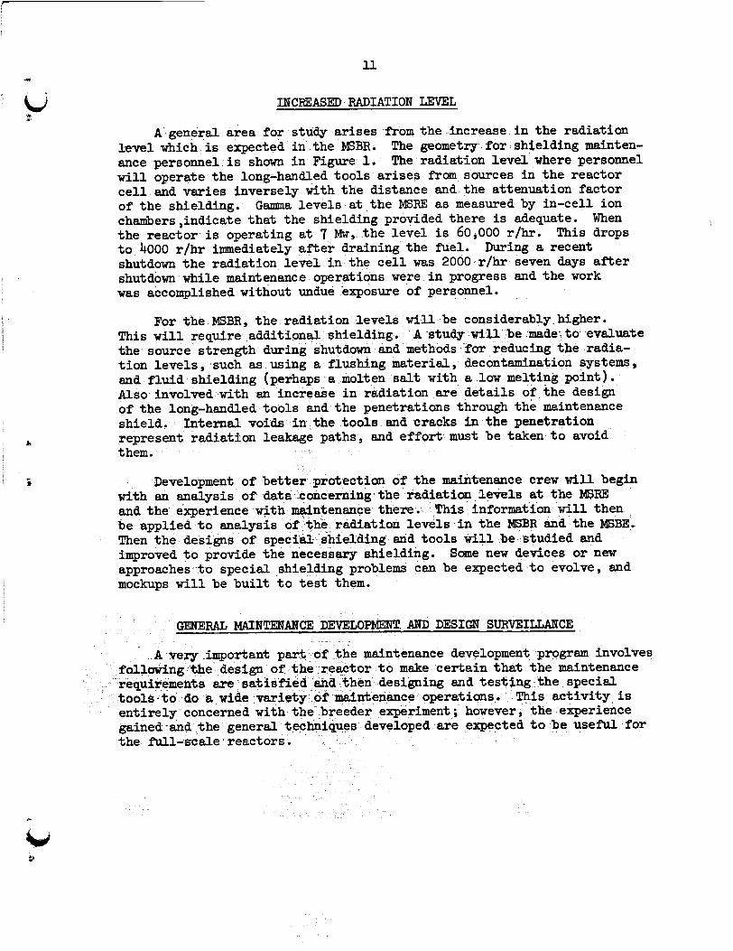
A general area for study arises f’romthe increase i n the radiation level which is expected i n the WBR. ance personnel i s shown i n Figure 1. w i l l operate the long-handled too ls a r i ses from sources i n t h e reactor c e l l and varies inversely with t h e distance and the attenuation factor of the shielding. Gamma levels at the MSRE as measured by in-cell ion chaaibers ,indicate tha t the shielding provided there is adequate. When the reactor is operating at 7 Mw, the level i s 60,000 r/hr. This drops t o 4000 r/hr immediately after draining the fuel. shutdown the radiation level i n the c e l l was 2000 r /hr seven days a f t e r shutdown while maintenance operations were i n progress and the work was accomplished without undue exposure of personnel.
The geometry f o r shielding mainten- The radiation l eve l where personnel
During a recent
For the MSBR, the radiation levels w i l l be considerably higher. This w i l l require additional shielding. the source strength during shutdown and methods for reducing the radia- t i on leve ls , such as using a flushing material, decontamination systems, and f lu id shielding (perhaps a molten salt w i t h a low melting point) . Also involved with an increldse i n radiation a re de t a i l s of the design of the long-handled tools and the penetrations through the maintenance shield. represent radiatfon leakage paths, and e f fo r t m u s t be taken t o avoid them.
A study w i l l be made t o evaluate
Internal voids i n the too ls and cracks i n t he penetration
Development of bet with an analysis of- dat and the experience w i t h enance there. This information w i l l then be applied t o analysis Then the designs of sp improved t o provide t h approaches t o special shielding problems can be expectedto evolve, and mockups w i l l be b u i l t t o t e s t them.
otection of the maintenance crew w i l l begin the radiation levels at the MSFE
radiation levels i n the MSBR and the MSBE, hielding and too ls w i l l be studied and s a r y shielding. Some new devices or new
GENERAL MAINTENANCE DEVELOPMENT. AND DESIGN SURVEILLANCE
important part o e design of t h
001s t o do a wide var ie ty
maintenance development program involves t o r t o make cer ta in that the maintenance
are sa t i s f i ed hen designing and tes ng the special ntenance operat ions This ac t iv i ty is
ent i re ly concerned w i t h the breeder experiment; however, the experience gained and the gener the -1-scale reactors.
loped are expected t o be useful for

12 L
u *
Fig. 1.
r
t
Shielding Configuration f o r Maintenance Operations.

13 m
L J This ac t iv i ty w i l l be carried out i n about the following sequence.
1. * I
Review preliminary flowsheets and equipment and plant designs t o make cer ta in that the maintenance requirements a re integrated in to the design of the plant. shielding arrangement with emphasis on special shielding fo r maintenance, the shielding penetrations, the component support s t ructures , the cranes and other equipment for handling radioactive components, and the view- ing devices.
Items of special importance include the
2. Prepare proposals for a l l maintenance operations. Compile l i s ts of problems, too ls and special disconnects.
3. Review f i n a l designs as they a re being made. Revise maintenance requirements as necessary.
4. Build required special t oo l s , j i g s and fixtures. T e s t them i n full-scale mockups and on the Engineering T e s t Unit.
5. Follow the construction of the MSBE and the ins ta l la t ion of the equipment t o be cer ta in tha t maintenance i s properly considered i f changes are made.
t 6, Prepare procedures fo r maintaining the equipment i n the MSBE.
i PROGRAM COSTS AND SCHEDULE
A preliminary estimate of the cost of the maintenance devebopment program f o r t h e MSBE i s shown i n Table 1. the schedule proposed i n ORNL-TM-1851 (Ref 2) for designing and building the plant. there is only one crucial development. welding the jo in ts i n the main fuel , blanket, and coolant l i nes and ves- s e l s o r some sui table a l ternat ive must be established before the design can be completed. The program is designed t o demonstrate a sat isfactory j o i n t by t h e end of FY 1970, although considerable t e s t ing and improve- ment of equipment and t ec
The ac t iv i t i e s are f i t t e d into
Although the maintenance considerations influence the design, The f eas ib i l i t y of remotely
e expected-'to follow the demonstration.
es tabl ish maintenance requirements I n t h e other areas w e and provide convincing evide schemes by the end of FY too l s and procedures w i l
the prac t ica l i ty of the maintenance ever, t he development o ished while the plant
.

Table 1. Estimate of Costs for Maintenance Development Program ( $ Thousands)
Remote Welding 120 230 250 180 150 100 70 70
Core Replacement and Repair
Maintenance of the Heat Exchangers and Other Component s
60
60
General Maintenance Develop- 60 ment and Design Surveillance -
300
160
100
160
100
100 100
60 60
120 120 60 60
610 630 400 370
50 30, 30
60 30 30
60 60 30 - - - 270 190 160

i
15
I .
8 .'$ REFERENCES
IP. R. Kasten, E. S. Bet t is and R. C . Robertson, Design Studies of lOOO-Mw( e) Molten-Salt Breeder Reactors , 0RN~-3996 (August 1966).
*R. B. Briggs, Summary of Objectives and a Program of Development of Molt en-Salt Breeder Reactors , ORNL-TM-1851 (June 1967) . 3E. C. R i s e , F. W. Cooke and R. G. Donnelly, "Remote Fabrication of Brazed Structural Jo in ts i n Radioactive Piping , I1 ASME 63-WA-53 (September 1964) . 4E. H . Seidler , "Welding ,I1 Advanced Fabrication Technolorn , Atomics International (Brochure).
5E. H. Seidler , Layout and Maintenance, WCAP-1104, Vol. I V , Part 1 (March 1959)
6R. R. Irving , "Welding Reacts t o New Demands ,I1 Iron Age 191(14) , pp. 83-90 (April 4 , 1963).

t

17
1 nt ern al Distribution
1.-50. MSRP Director's Office 99. H. A. Friedman 51. R. K. Adams 100. J. H. Frye, Jr. 52. G. M. Adamson 101. C. H. Gabbard 53. R. G. A f f e l 102. R. B. Gallaher 54. L. G. Alexander 103. H. E. Goeller 55. R. F. Apple 104. W. R. G r i m e s 56. C. F. Baes 105. A. G. Grindell 57. J. M. Baker 106. R. H. Guymon 58. S. J. B a l l 107. B. A. Hannaford 59. W. P. Berthold 108. P. H. Harley 60. H. F. Bauman 109. D. G. Harman 61. S. E. B e a l l 110. C. S. Harrill 62. M. Bender 111. P. N. Hadenreich 63. E. S. Bettis 112. F. A. Heddleson 64. F. F. Blankenship 113. P. G. Herndon 65. R. E. Blanco 114. J. R. Hightower 66. J. 0. Blomeke 115. H. W. Hoffman
67.-71. R. Blumberg 116. R. W. Horton 72. E. G. Bohlmann 117. T. L. Hudson 73. C. J. Borkowski 118. H. Inouye 74. G. E. Boyd 119. W. H. Jordan 75. J. Braunstein 120. P. R. Kasten 76. M. A. Bredig 121. R. J. Ked1 77. R. B. Briggs 122. M. T. Kelley 78. H. R. Bronstein 123. M. J. Kelly 79. G. D. Brunton 124. C. R. Kennedy 80. D. A. Canonico 125. TI W. Kerlin 81. S . Cantor 126. H. T. Kerr 82. W. L. Carter 127. S . S . Kirslis 83. G. I. Cathers 128. A. I. Krakoviak 84. J. M. Chandler 129. J. W. Krewson 85. E. L. Compere 130. C. E. Lamb 86. W. H. Cook 131. J. A. Lane 87. L. T. Corbin 132. R. B. Lindauer 88. J. Le Crowley 133. A. P. L i t m a n 89. F. L. Culler 134. M. I. Lundin 90. J. M. Dale 135. R. N. Lyon 91. D. G. D a v i 136. H. G. MacPh 92. S. J. Ditto 137. R. E. MacPherson 93. A. S. Dworkin 138. C. D. Martin 94. J. R. Engel 139. C. E. Mathews 95. E. P. Epler 140. C. L. Matthews 96. D. E. Ferguson 141. R. W. McClung 97. L. M. Ferr is 142. H. C. McCoy 98. A. P. Fraas 143. H. F. McDuffie
144. C.' K. McGlothlan

145. 146 . 147. 148. 149. 150. 151. 152. 153- 154. 155
157
159
156.
158.
160. 161. 162. 163.
165. 164.
C. J. McHargue L. E. McNeese A. S. Meyer R. L. Moore J. P. Nichols E. L. Nicholson L. C. Oakes P. Patriarca A. M. Perry H. B. Piper B. E. Prince J. L. Redford M. Richardson R. C. Robertson H. C. Roller H. C. Savage C. E. Schill ing Dunlap Scott H. E. Seagren W. F. Schaffer J. H.* Shaffer
18
171. 172.
174. 173
175
177 9
179
176.
178.
180. 181. 182. 183.
185. 186. 187. 188. 189. 190. 191 0
184.
0. L. Smith P. G. Smith W. F. Spencer I. Spiewak R. C. Steffy H. H. Stone J. R. Tallackson E. H. Taylor R. E. Thoma J. S. Watson C. F. Weaver B. H. Webster A. M. Weinberg J. R. Weir W. J. Werner K. W. West M. E. Whatley J. C. White L. V. Wilson G. Young H. C. Young
’r
Bd I
166. M. J. Skinner 192. -193. Central Research L i b r a r y 167. G. M. Slaughter 194.-195. Document Reference Section
169. F. J. Smith 206. Laboratory Records (LRD-RC) 168. A. 8. Smith 196.-205. Laboratory Records (LRD) ,r
170. G. P. Smith
E x t e r n a l Distribution
207.-208. 209. 210.
2ll.-225. 226.
227.-228. 229. 230.
231.-245. 246.
247.-248. Reactor Division, OR0
D. F. Cope, Atomic Energy Commission, RIlISite Office A. Giambusso, Atomic Energy Commission, Washington W. J. Larkin, Atomic Energy Commission, OR0 T. W. McIntosh, Atomic Energy Commission, Washington H. M. Roth, Atomic Energy Commission, OR0 M. Shaw, Atomic Energy Commission, Washington W. L. Smalley, Atomic Energy Commission, OR0 R. F. Sweek, Atoonic Energy Commission, Washington Division of Technical Information Extension (DTIE) Research and Development Division, OR0
!