Embed Size (px)
Citation preview
ORNL/LTR-2014/515
Preliminary Development of a Work Breakdown Structure for Small Modular Reactors
T. Jay Harrison Rebecca J. Moses George F. Flanagan October 2014
Approved for public release; distribution is unlimited.

This report was prepared as an account of work sponsored by an agency of the United States Government. Neither the United States Government nor any agency thereof, nor any of their employees, makes any warranty, express or implied, or assumes any legal liability or responsibility for the accuracy, completeness, or usefulness of any information, apparatus, product, or process disclosed, or represents that its use would not infringe privately owned rights. Reference herein to any specific commercial product, process, or service by trade name, trademark, manufacturer, or otherwise, does not necessarily constitute or imply its endorsement, recommendation, or favoring by the United States Government or any agency thereof. The views and opinions of authors expressed herein do not necessarily state or reflect those of the United States Government or any agency thereof.
ORNL/LTR-2014/515
Reactor and Nuclear Systems Division
PRELIMINARY DEVELOPMENT OF A WORK BREAKDOWN STRUCTURE FOR SMALL MODULAR REACTORS
T. Jay Harrison Rebecca J. Moses
George F. Flanagan
Date Published: October 2014
Prepared by OAK RIDGE NATIONAL LABORATORY
Oak Ridge, Tennessee 37831-6283 managed by
UT-BATTELLE, LLC for the
US DEPARTMENT OF ENERGY under contract DE-AC05-00OR22725

iii
CONTENTS
Page
ACRONYMS ................................................................................................................................................ v ABSTRACT ................................................................................................................................................ vii 1. INTRODUCTION ................................................................................................................................ 1 2. CONCEPTUAL WORK BREAKDOWN STRUCTURE FOR ELECTRIC POWER
PRODUCTION IN GIGAWATT-CLASS REACTORS ..................................................................... 3 2.1 GIGAWATT-CLASS REACTORS ........................................................................................... 3
2.1.1 Site Work ....................................................................................................................... 3 2.1.2 Reactor and Balance-of-Plant Work .............................................................................. 4 2.1.3 Power Production and Decommissioning ...................................................................... 5
3. WBS DIFFERENCES FOR SMRS ...................................................................................................... 7 3.1 PROBABLE COMMON FEATURES FOR ALL SMALL MODULAR REACTORS ............ 7
3.1.1 Site Preparation .............................................................................................................. 7 3.1.2 Ante-Reactor Module ..................................................................................................... 7 3.1.3 Reactor ........................................................................................................................... 7 3.1.4 Post-Reactor Module ..................................................................................................... 8 3.1.5 Multi-Unit Considerations ............................................................................................. 8
4. DESCRIPTION OF NEAR-TERM SMRs ........................................................................................... 9 4.1 BACKGROUND ........................................................................................................................ 9 4.2 CLASSES OF SMRs RELATIVE TO gigawatt-CLASS REACTORS ..................................... 9
4.2.1 SMRs Similar to Gigawatt-Class Reactors .................................................................... 9 4.2.2 SMRs with some Departure from Gigawatt-Class Reactors .......................................... 9 4.2.3 SMRs with Significant Departure from Gigawatt-Class Reactors ................................. 9
5. DIFFERENT CLASSES OF SMRs .................................................................................................... 11 5.1 SMRs SIMILAR TO GIGAWATT-CLASS REACTORS ....................................................... 11 5.2 SMRs WITH SOME DEPARTURE FROM GIGAWATT-CLASS REACTORS .................. 11 5.3 SMRs WITH SIGNIFICANT DEPARTURE FROM GIGAWATT-CLASS
REACTORS .............................................................................................................................. 11 6. WBS FOR POWER AND HEAT PRODUCTION AND HYBRID SYSTEMS ............................... 13
6.1 COMBINED HEAT AND POWER SYSTEMS AND THEIR POTENTIAL WBS CHANGES ................................................................................................................................ 13
6.2 HYBRID SYSTEMS ................................................................................................................ 13 7. WBS FOR REPURPOSED SITES (COAL REPLACEMENT) ........................................................ 15
7.1 SITE-RELATED WBS ELEMENTS ....................................................................................... 15 7.2 OTHER WBS ELEMENTS ...................................................................................................... 15
8. WBS FOR ADVANCED REACTORS .............................................................................................. 17 9. SUMMARY ........................................................................................................................................ 19 10. REFERENCES ................................................................................................................................... 21 11. BIBLIOGRAPHY ............................................................................................................................... 23 APPENDIX A. WBS TABLES FOR GIGAWATT-CLASS REACTORS AND SMRs ......................... A-1

v
ACRONYMS
B&W Babcock and Wilcox EPZ emergency planning zone IAEA International Atomic Energy Agency I&C instrumentation and controls ITAAC inspections, tests, analyses, and acceptance criteria LWR light water reactor NRC US Nuclear Regulatory Commission PM/CM Project management/construction management PWR pressurized water reactor SMR small modular reactor WBS work breakdown structure


vii
ABSTRACT
The construction of a typical nuclear power plant in the United States spans most of a decade and potentially changes in electricity market conditions. This long time from decision to deployment has several stages of design, construction, testing, regulatory work, and eventual operation. Understanding these stages allows planners to understand better how to deploy these capital-intensive assets successfully.
The most recent history in the United States’ nuclear power industry is heavily weighted towards the construction of gigawatt-class reactors. Current ongoing construction includes the two Westinghouse AP1000 reactors each at Summer (in South Carolina) and Vogtle (in Georgia) and the completion of another Westinghouse pressurized water reactor (PWR) rated at over 1100 MW(e) at Watts Bar (in Tennessee). Prior to these reactors, the last reactor to come online in the United States was Watts Bar Unit 1, which is a twin of the unit currently under construction.
However, the United States’ nuclear power industry has indicated interest in small modular reactors (SMRs), which would be a shift from the gigawatt-class reactor paradigm. There are several reasons for this interest, one of which is the potential benefit of simplifying and shortening the construction and deployment process; this could translate to savings in both time and money.
As mentioned, the recent domestic experience base for nuclear power plant construction does not include anything other than the gigawatt class. Thus, an examination of the work breakdown structure (WBS) of the large projects must serve as a starting point for SMR WBS analysis. However, the issue is complicated by the diversity of current SMR designs. The Babcock &Wilcox (B&W) and Westinghouse designs approximate scaled-down versions of the large reactors, but the NuScale design departs from that paradigm with its multiple, staged, planned-expansion approach. Other designs may represent greater divergence from the industry experience base. Therefore, the derivation and description of an SMR WBS must be generic enough to handle these different approaches.
To this end, this report provides a generic gigawatt-class reactor WBS that was culled and combined from multiple sources, then examines where it would differ for SMRs. The contrast and comparison of the SMR and gigawatt-class reactors can then help guide the development of deployment scenarios that could lead to SMR success in the nuclear power industry. The net result is that the WBS depends more on the complexity of the application and overall system than it does on the individual reactor design.
Taking the existing light water reactor (LWR) WBS as the starting point and moving towards PWR-based SMRs does not change the WBS as a whole, but it likely changes the duration of specific activities, especially for SMRs similar to the gigawatt-class LWRs. Changing the duration of specific activities, such as the length of time necessary to pour a basemat or build a containment building, may or may not affect the total length of the overall activity. This is because of the parallel nature of some of the tasks involved in the construction and startup: shortening an activity that may not have been the longest-lead item may not shorten the overall process.
The use of factory-fabricated modules will also have an impact on the overall time required for construction. If system and component fabrication can be relocated from the site to a controlled factory environment, this can change some serial activities to parallel activities.
For SMRs with planned multi-unit deployment, the WBS becomes an iterative process. The point at which the iteration occurs depends on the type of design. For example, a multi-unit site at which the units do not share a containment building would resemble the work being performed at Vogtle and Summer. In this example, the iteration point would be essentially immediately after the site preparation step. Conversely, a multi-unit site at which the units share a containment building, such as the concept for the NuScale plant, would have an iteration point after the completion of the shared containment building.
For applications beyond electricity production, the presence of additional power trains (or sources) requires flexibility in the WBS for the integration of the systems. If thermal energy from multiple sources

viii
is to be collected, stored, and/or distributed among multiple loads, this system is by necessity both a part of the nuclear reactor WBS at its interface points and apart from the nuclear reactor WBS at the other interface points. Similarly, if the electric power conversion and transmission system aggregates and distributes electricity from multiple sources to multiple loads, the control system for this dynamic load balance must be considered within the context of the nuclear reactor WBS.
Advanced reactors deployed without collocated fuel cycle facilities should have WBSs similar to those for LWRs, with the overall complexity being a function of the application. However, the type of advanced reactor may influence the total scope of the WBS. For example, an atmospheric pressure system may require a smaller containment building than a reactor operating at high pressure; this may shorten and/or simplify parts of the WBS. Conversely, a reactor using non-water coolant may require special coolant handling, treatment, and purification facilities, which would add to the overall WBS. Further deviation from the LWR WBS will likely be based on fuel cycle considerations. For example, any advanced fuel cycle facility located at the site will require its own set of activities within the WBS.
In summary, this preliminary WBS serves as an initial basis for the capital cost component of the economic analysis of SMRs. This preliminary WBS comes from the known WBS for existing, large nuclear power plants and develops the methodology for accounting for the anticipated differences between the current large plants and the projected SMR designs.

1
1. INTRODUCTION
This report compares and contrasts a high-level work breakdown structure (WBS) for a gigawatt-class reactor with a conceptual WBS for small modular reactors (SMRs). The differentiation examines the WBS for multiple proposed applications of nuclear reactors or SMRs. The most common use for nuclear reactors is to produce electric power starting with greenfield construction. This work is done as part of DOE-NE’s Advanced Small Modular Reactor program, and is part of a set of economics-centric letter reports. These are listed at the end of the Reference section.
However, there is significant interest in the use of nuclear power plants—especially SMR designs—in nontraditional roles, including nuclear-renewable hybrid systems, combined generation of process heat and power, and replacement for existing coal-fired power generation. This report focuses on the traditional application of generating electricity, but it also addresses the aforementioned additional applications of SMRs these potential expansions to the nuclear portfolio.

3
2. CONCEPTUAL WORK BREAKDOWN STRUCTURE FOR ELECTRIC POWER PRODUCTION IN GIGAWATT-CLASS REACTORS
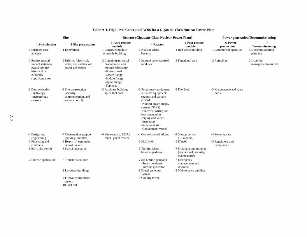
This section details a conceptual WBS for nuclear power plants built for dedicated electricity generation. There is no distinction between plants built in regulated versus unregulated market environments. A high-level conceptual WBS for the gigawatt-class nuclear power plant is shown in Table A-1 in Appendix A, and the corresponding WBS for the SMR nuclear power plant is shown in Table A-2.
By necessity these phases will have some overlap in some areas, but may be restricted from overlapping in others. For example, some work on reactor infrastructure would necessarily coincide with site preparation, and some ongoing site upkeep would continue well into operation, but operation cannot begin until the construction is complete. For simplicity, this analysis does not consider overlap.
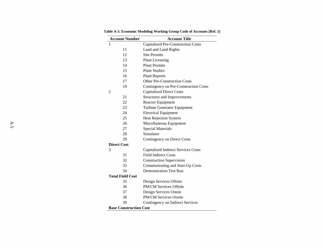
For reference, the Generation IV International Forum Economic Modeling Working Group Code of Accounts [Ref. 1] will be used to group costs for comparison. The Code of Accounts for construction appears in Appendix A as Table A-3.
2.1 GIGAWATT-CLASS REACTORS
The WBS for the gigawatt-class nuclear power plant is divided into seven discrete activities organized under three general phases. The three phases cover the site, reactor, and operation and decommissioning. These phases follow a logical chronological progression from the start of the reactor construction project through its shutdown and eventual return to a greenfield condition.
2.1.1 Site Work
Site work can be separated into two activities: site selection and site preparation. Historically, many US nuclear power projects did not proceed past this phase. For example, Phipps Bend went through site selection and some limited site preparation, but it did not proceed into full reactor or balance-of-plant construction.
Site work for a gigawatt-class nuclear power plant can range from a few years for active construction projects, to more than a decade for delayed projects. For example, the Summer nuclear power plant construction project started in 2008 with a site already identified and characterized at the existing Summer nuclear power plant. In 2012, the license for construction was issued, and in 2013, construction began. Similarly, the Vogtle nuclear power plant construction project started in 2006 with an existing site, received an early site permit license in 2009 and a construction license in 2012, and began construction in 2013.
2.1.1.1 Site selection
The first activity in site work is the selection of the site itself. Multiple criteria affect the selection of the site itself, including economic, environmental, and regulatory considerations.
The total cost of building on a site is a function of multiple cost objects. The site must either be purchased from its current owner or taken from existing property owned by the reactor plant developer. If the site is not near the customer base, and not near existing transmission capacity, new transmission capacity must be added, which represents an added expense. These expenses are in the code of accounts under Account 1.
4
From an environmental perspective, the site must provide an environmental impact statement in accordance with US Nuclear Regulatory Commission (NRC) requirements. The cost to comply with environmental requirements also affects the potential cost of construction at the site; this impacts the economic evaluation as well.
Other NRC requirements may also affect the economic analysis of the site selection beyond the capital or development cost. For example, the emergency planning zone (EPZ) for light water reactors (LWRs) is described in NUREG-0396. The logistics and planning costs for the EPZ may make a site economically unattractive.
Further, before work can begin, the operator must obtain a license from the NRC for the construction and operation. This in itself represents a large investment in both time and money.
2.1.1.2 Site preparation
After selecting the site, site preparation may begin. This includes site excavation, levelling, utility installation, and ancillary support structures. This may also include the construction of a railroad spur for fuel transportation. These costs also fall under Account 1, as well as some of Account 2.
The site preparation work is distinct from the reactor installation in that none of the work necessarily requires NRC approval to commence, although regulatory matters may influence the work, such as the location of the nuclear island. While much of the work may directly impact the construction of the reactor itself (such as excavation and utility installation), it is not by itself reactor or balance-of-plant installation.
2.1.2 Reactor and Balance-of-Plant Work
The majority of work is performed in the second phase. This phase may be subdivided into three activities, which can be performed in a combination of serial and parallel actions. This phase ends once operation begins.
During a typical gigawatt-class reactor construction project, the time required for the reactor construction phase is around 3-4 years. Both the Summer and Vogtle plants began construction in 2013 and plan to bring the first of the new reactors online in 2016–17.
2.1.2.1 Ante-reactor module
The ante-reactor work includes the erection of buildings, whether temporary or permanent, necessary for the construction of the nuclear reactor, fuel cycle buildings, and balance of plant. This also includes work on the containment vessel and security infrastructure, such as fences, towers, and perimeter alarms.
2.1.2.2 Reactor
The work on the reactor portion includes the nuclear island, most of the balance of plant, instrumentation and control (I&C) systems, and the control room. This also includes the diesel generator systems and cooling towers.
2.1.2.3 Post-reactor module
The post-reactor work completes any remaining construction and prepares the site for commercial operation. In this activity, any remaining regulatory issues are addressed, such as through inspections, tests, analyses, and acceptance criteria (ITAAC). Fuel is loaded and startup has begun.
5
2.1.3 Power Production and Decommissioning
This phase covers two activities: the relatively steady-state power production, and the decommissioning at the end of life. The overlap between these activities is limited to decommissioning preparation begun while the plant is still operating.
The duration of the operating period is typically on the order of decades, with 40 to 60 years now the standard planning assumption. The time required for decommissioning and returning to a greenfield state is variable, with a lack of recent experience in immediately returning reactor sites to greenfield. However, the NRC requires decommissioning to be completed within 60 years of the cessation of operations.
2.1.3.1 Power production
During the lifetime of power production, some continued construction is expected, whether renovating existing buildings, replacing components such as steam generators, or expanding the site to include new reactors. Other work will be in response to new or changing regulatory requirements, such as responses to 9/11 security requirements, Fukushima safety requirements, or license renewal.
2.1.3.2 Decommissioning
Once the reactor achieves final shutdown, the plant goes into decommissioning. Currently, the NRC allows three decommissioning strategies:
• DECON—immediate dismantling in which materials are removed or decontaminated to a level that permits release of the property.
• SAFSTO—maintenance and monitoring of the plant for some period of time before proceeding to DECON.
• ENTOMB—permanent encasement of contamination in a material such as concrete. To-date, no NRC licensee has requested this option.
Further, a licensee may elect some combination of DECON and SAFSTOR, in which some parts of the plant site undergo immediate dismantling and other parts undergo continued maintenance and monitoring before dismantling.

7
3. WBS DIFFERENCES FOR SMRS
3.1 PROBABLE COMMON FEATURES FOR ALL SMALL MODULAR REACTORS
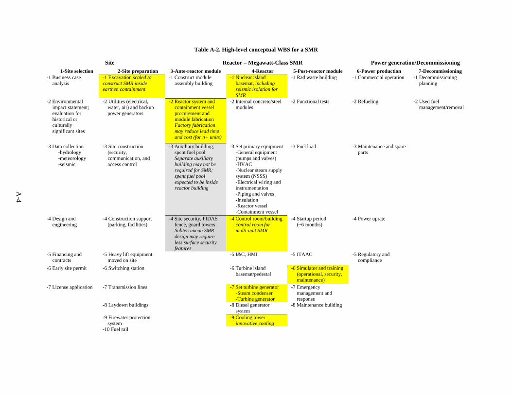
Table A-2 in Appendix A shows a probable common WBS for all SMRs. This table differs from Table A-1 in some key areas. These areas are discussed in the following sections.
3.1.1 Site Preparation
The primary difference in the WBS for SMRs relative to the gigawatt-class reactors is the use of underground or below-grade containment. Current containment buildings sit on concrete foundations, but they are typically at ground level. The current SMR designs (see Sect. 4) share a philosophy of below-grade construction.
3.1.2 Ante-Reactor Module
The ante-reactor module activity will likely differ for SMRs. The envisioned plan for SMRs is to use factory standardization and fabrication to expedite the construction of the reactors and other components. This will not remove the activity, but it would decrease the elapsed time required.
The introduction of factory fabrication of modules will also affect the elapsed time. This will allow what is currently a serial process requiring site preparation to reach an acceptable level of completion to change to a parallel process. The relocation of field work to a controlled factory environment may also accelerate the process itself by introducing greater quality control capabilities and reducing re-work.
Furthermore, the auxiliary building may be combined with the spent fuel pool in order to reduce the overall plant footprint. This also reflects the reduced fresh and spent fuel inventory associated with smaller cores. While the fuel inventory per energy output for small reactors may be similar to large reactors, the total mass per core will be reduced.
Finally, below-grade containment, or advanced inherently-safe designs, may change the security requirements, which may affect the construction, configuration, and total footprint of site security.
3.1.3 Reactor
The nuclear island for SMRs will likely be underground, and it will also likely include seismic isolation for the SMRs. An SMR paradigm also calls for modular construction and installation of components and systems. This is a significant departure from the stick-built methodology of the gigawatt-class reactor.
The control room for SMRs may also differ from the current paradigm. Some designs will align with the current operational methodology, both with respect to the number of reactors and the number of operators per reactor. Other designs will seek to test the regulatory requirements on the number of operators, and will also seek to expand the operational envelope with as many as 12 reactors controlled from a single room.
The design and construction of the balance of plant, including the steam condenser and turbine generator, will also be a function of the number of units and the method for integration. Shared steam lines or shared turbine generators will require different methods for construction from isolated systems.
Some SMR designs also provide an option for air cooling as the ultimate heat sink. This will also require a different construction methodology; it will also affect the siting studies.
8
3.1.4 Post-Reactor Module
The simulator and training activity must account for all the changes given in the site preparation, ante-reactor module, and reactor activities.
3.1.5 Multi-Unit Considerations
Another factor to consider for SMRs is the deployment of multiple units at a site. Currently, the addition of another unit at an existing site requires the construction of a new containment and a new nuclear island. For some designs, the planned deployment includes the addition of new units within existing containment. The WBS for those then becomes a shared iterative process, in which the site itself progresses through the WBS to a common starting point, and each reactor progresses by itself through the remainder of the WBS.
This is similar to the current process. For example, at Summer and Vogtle, the sites were selected, and the existing units had already progressed through to power production. The new units started with site preparation and continued from that point. For a shared containment, the site would be selected and prepared, and the containment would be built, but each reactor would go through completion and startup individually.
9
4. DESCRIPTION OF NEAR-TERM SMRs
4.1 BACKGROUND
Near-term SMRs will share many technological and operational characteristics with the LWRs already operating and those under construction since the three primary near-term SMR concepts are variations of existing pressurized water reactor (PWR) technologies. The four primary concepts are products of Westinghouse, Babcock and Wilcox (B&W), Holtec, and NuScale.
4.2 CLASSES OF SMRs RELATIVE TO GIGAWATT-CLASS REACTORS
The different designs can be separated into their own classes relative to the gigawatt-class reactor paradigm. The primary basis for this differentiation is the power output. Generally speaking, it is assumed that as the power output for each reactor approaches the power output of the existing or under-construction reactors, the sizing, and therefore the WBS for handling, of components and systems should converge. Likewise, as the output decreases and the component sizes diverge, the WBS should also diverge.
4.2.1 SMRs Similar to Gigawatt-Class Reactors
The Westinghouse SMR has a design output of 225 MW(e) [Ref.2]. There is no detail given on whether it is intended as a single-unit or multi-unit site; however, since the AP1000 plants are typically deployed as two-unit sites, it is reasonable to assume that the SMR would be as well. At 225 MW(e), this is smaller than the smallest currently operating US nuclear power plant (Fort Calhoun, 476 MW(e) [Refs. 3, 4]). However, a two-unit site would have approximately the same output. In most respects, this can be regarded as a smaller version of the current gigawatt-class reactor paradigm.
4.2.2 SMRs with some Departure from Gigawatt-Class Reactors
The B&W (now Generation mPower) design is the mPower. This is envisioned as a multi-unit (one or two units) plant, with each unit generating 155 MW(e) for an air-cooled condenser and 180 MW(e) for a water-cooled condenser [Ref. 5]. The explicit description of potential air cooling deviates from the current practice of water cooling, whether by reservoir or flowing water. The potential use of air cooling as an ultimate heat sink makes this design a more significant departure from the gigawatt-class reactor paradigm.
Holtec calls its design the Holtec Inherently-Safe Modular Underground Reactor. It is planned at 160 MW(e) output [Ref. 6]. This design also includes the option for air cooling, but no differentiation in output between air cooling and water cooling is given. This design differs from the Generation mPower, but from a WBS perspective, they share enough similarities to be considered in a single class.
4.2.3 SMRs with Significant Departure from Gigawatt-Class Reactors
The NuScale design uses up to 12 units rated at ~50 MW(e) each in a shared pool inside containment [Ref. 7]. The output of the units, the number of units at the site, and the shared pool inside containment make the NuScale design the greatest departure from the gigawatt-class reactor paradigm.


11
5. DIFFERENT CLASSES OF SMRs
5.1 SMRs SIMILAR TO GIGAWATT-CLASS REACTORS
The Westinghouse SMR has two factors that make it similar to the gigawatt-class reactor: its corporate relationship to the AP1000 and the relatively large output of the reactor. The WBS for the Westinghouse SMR should be closely related to that of the AP1000, with the main differences being in the total amounts of time required for the construction and installation of the systems, structures, and components.
5.2 SMRs WITH SOME DEPARTURE FROM GIGAWATT-CLASS REACTORS
The B&W and Holtec designs share the same potentially-compressed schedule that the Westinghouse design does. Further, they will also require new approaches to the control room if they are deployed with multiple units, especially if they depart from the single unit per operator requirement. Finally, if the air cooling option is pursued, they will require different balance-of-plant systems.
5.3 SMRs WITH SIGNIFICANT DEPARTURE FROM GIGAWATT-CLASS REACTORS
The NuScale design also falls in line with the previous designs. However, the NuScale by design will require a novel approach to the simulator and training methodology because of its intention to use a single operator for multiple reactors. The construction and commissioning of additional reactors in the shared pool and used fuel management for shut-down reactors while the other reactors operate also represent a significant departure from the current system.


13
6. WBS FOR POWER AND HEAT PRODUCTION AND HYBRID SYSTEMS
Another potential change in the WBS for SMRs would be in the introduction of combined power and heat production or in hybridized systems.
6.1 COMBINED HEAT AND POWER SYSTEMS AND THEIR POTENTIAL WBS CHANGES
A combined heat and power system is self-explanatory: it provides both heat and electric power. It could provide these to an industrial customer or to residential customers; regardless, the balance of plant would require equipment to accommodate a splitting of the power output.
The main change in the WBS would be in the reactor activity. The steam condenser and turbine generator would share the power load with some industrial heat load. Feedback effects from that industrial load must be accounted for with the control systems and I&C systems. The equipment for transporting the thermal power would also have to be installed alongside the power generation equipment.
6.2 HYBRID SYSTEMS
“Hybrid system” refers to an integrated power generation system that includes nuclear thermal and/or electrical power generation; potentially other dispatchable thermal and/or electrical power generation sources (such as natural gas or coal); renewable thermal and/or electrical power generation sources (such as wind and solar); and end users for both thermal and electrical power, including dedicated industrial uses. For example, a hybrid system might combine a nuclear reactor and a windmill as electrical generators with an industrial customer and a grid tie-in. When market conditions are favorable for selling the electricity on the grid, the power would be sold; otherwise, the power would be used by the industrial customer. An additional level of complexity would divert thermal power from the reactor instead of electrical power.
The specifics of the hybrid system are highly dependent on the type of hybrid system itself. In general, the hybrid system would impact the WBS based on where the integration point occurred. If the system is integrated between the turbine generator and the grid, then the integration would be essentially seamless from the WBS perspective. As the integration point moves towards the reactor, the overall system becomes coupled, introducing complexities to the WBS. The overall WBS of a hybrid system would thus be a function of the hybrid system.

15
7. WBS FOR REPURPOSED SITES (COAL REPLACEMENT)
Another application for SMRs is to repower existing coal sites. This changes the WBS as well.
7.1 SITE-RELATED WBS ELEMENTS
The selection of an existing site changes the process of site selection and site preparation. Much of the non-nuclear infrastructure, including switching station and transmission lines, would already exist. In effect, some of the work would already be done. However, the construction of a nuclear reactor at a coal-fired power plant site would likely require the demolition of some existing structures. Further, the existing structures might require upgrading to meet the requirements for safety and security.
7.2 OTHER WBS ELEMENTS
After preparing the site for nuclear construction, the remainder of the WBS would probably follow the WBS as planned for power generation, combined heat and power, or for hybrid systems. Potential complications might be the logistics of planning around existing structures.


17
8. WBS FOR ADVANCED REACTORS
The WBS for most non-LWRs could likely follow the WBS as described for each application. The primary difference would be based on fuel cycle considerations. For example, a fast reactor with on-site reprocessing and fabrication would require an additional set of activities dedicated to the construction of the fuel handling facilities. Likewise, a molten salt reactor would require a set of activities dedicated to the construction of the chemical processing facilities.

19
9. SUMMARY
The WBS for reactor construction depends heavily on the application and the complexity of the overall system. Taking the current LWR WBS as the baseline, the change from gigawatt-class to SMRs is generally a matter of changing the total elapsed time for each activity. Changing operational paradigms adds complexity in the technology, but not necessarily in how the power plant is built. Changes in the control room and operations perspectives, such as NuScale, will require more effort devoted to those activities in the WBS, but it will not necessarily change the order of operations.
Advanced systems, including hybrid systems or combined generation systems, complicate the WBS by adding activities to account for system integration. Moving towards advanced reactors does not necessarily require more activity in the WBS, but moving towards collocated advanced fuel cycle facilities will.


21
10. REFERENCES
1. Economic Modeling Working Group of the Gen IV International Forum, User’s Manual for
G4-ECONS Version 2.0, Nuclear Energy Agency, March 2008.
2. Westinghouse, “The Westinghouse Small Modular Reactor,” http://westinghousenuclear.com/New-Plants/Small-Modular-Reactor, accessed September 8, 2014.
3. Reassessment of NRC’s Dollar Per Person-Rem Conversion Factor Policy, NUREG-1530, Vol. 26, Appendix A, December 1995.
4. Wikipedia, “Fort Calhoun Nuclear Generating Station,” http://en.wikipedia.org/wiki/Fort_Calhoun_Nuclear_Generating_Station, accessed September 8, 2014.
5. Generation mPower, B&W, “Integral Small Modular Reactor,” http://www.generationmpower.com/pdf/sp201100.pdf, accessed September 8, 2014.
6. Holtec Technical Bulletin, SMR 160, http://www.smrllc.com/download/htb-015-hi-smur-rev3.pdf, accessed September 8, 2014.
7. NuScale Power, “Available for a Wide Range of Commercial Government Applications,” http://www.nuscalepower.com/commercialapplications.aspx, accessed September 8, 2014.
8. T. Jay Harrison, “Advanced Small Modular Reactor Economics Model Development”, ORNL/LTR-2014/516, October 2014
9. T. Jay Harrison, “Advanced SMR Economics Status Report”, ORNL/LTR-2014/560, October 2014
10. T. Jay Harrison, “Advanced SMR Economics Analysis”, ORNL/LTR-2014/578, October 2014


23
11. BIBLIOGRAPHY
1. International Atomic Energy Agency, Project Management in Nuclear Power Plant Construction: Guidelines and Experience, NP-T-2.7, Vienna, 2012.
2. International Atomic Energy Agency, Construction Technologies for Nuclear Power Plants, NP-T-2.5, Vienna, 2011.
3. US Nuclear Regulatory Commission, “Potential Policy, Licensing, and Key Technical Issues for Small Modular Nuclear Reactor Designs,” SECY-10-0034, March 28, 2010.
4. US Nuclear Regulatory Commission, “License Structure for Multi-Module Facilities Related to Small Modular Nuclear Power Reactors,” SECY-11-0079, June 12, 2011.
5. US Department of Commerce, “The Commercial Outlook for U.S. Small Modular Nuclear Reactors,” Washington, D.C., February 2011.
6. Admed Abdulla, Ines Lima Azevedo, and M. Granger Morgan, “Expert Assessments of the Cost of Light Water Small Modular Reactors,” PNAS 2013 110 (24) 9686-9691.
7. International Atomic Energy Agency, Status of Small and Medium Sized Reactor Designs, September 2011.
8. Dominion Virginia Power, Nuclear Power 2010 Program Dominion Virginia Power Cooperative Project, Construction and Operating License Demonstration Project Final Report, November 2010.
9. KAERI Nuclear Training Center, “Nuclear Power Project Management: Chapter 8. Implementation Phase for Nuclear Power Project Management.”
10. International Atomic Energy Agency, “Advanced Construction Methods for New Nuclear Power Plants.”
11. MPR, Application of Advanced Construction Technologies to New Nuclear Power Plants, MPR-2610, Rev. 2, September 2004.
12. US Department of Energy, Work Breakdown Structure Handbook, Washington, D.C., 2012.

APPENDIX A. WBS TABLES FOR GIGAWATT-CLASS REACTORS AND SMRs

A-3
Table A-1. High-level Conceptual WBS for a Gigawatt-Class Nuclear Power Plant
Site Reactor (Gigawatt-Class Nuclear Power Plant) Power generation/Decommissioning
1-Site selection 2-Site preparation 3-Ante-reactor module 4-Reactor 5-Post-reactor
module 6-Power
production 7-
Decommissioning -1 Business case
analysis -1 Excavation -1 Construct module
assembly building -1 Nuclear island
basemat -1 Rad waste building -1 Commercial operation -1 Decommissioning
planning
-2 Environmental impact statement; evaluation for historical or culturally significant sites
-2 Utilities (electrical, water, air) and backup power generators
-2 Containment vessel procurement and module fabrication
-Bottom head -Lower flange -Middle flange -Upper flange -Top head
-2 Internal concrete/steel modules
-2 Functional tests -2 Refueling -2 Used fuel management/removal
-3 Data collection -hydrology -meteorology -seismic
-3 Site construction (security, communication, and access control)
-3 Auxiliary building, spent fuel pool
-3 Set primary equipment -General equipment
(pumps and valves) -HVAC -Nuclear steam supply
system (NSSS) -Electrical wiring and
instrumentation -Piping and valves -Insulation -Reactor vessel -Containment vessel
-3 Fuel load -3 Maintenance and spare parts
-4 Design and engineering
-4 Construction support (parking, facilities)
-4 Site security, PIDAS fence, guard towers
-4 Control room/building
-4 Startup period (~6 months)
-4 Power uprate
-5 Financing and contracts
-5 Heavy lift equipment moved on site
-5 I&C, HMI -5 ITAAC -5 Regulatory and compliance
-6 Early site permit -6 Switching station
-6 Turbine island basemat/pedestal
-6 Simulator and training (operational, security, maintenance)
-7 License application -7 Transmission lines -7 Set turbine generator -Steam condenser -Turbine generator
-7 Emergency management and response
-8 Laydown buildings -8 Diesel generator system
-8 Maintenance building
-9 Firewater protection system
-9 Cooling tower
-10 Fuel rail
A-4
Table A-2. High-level conceptual WBS for a SMR
Site Reactor – Megawatt-Class SMR Power generation/Decommissioning 1-Site selection 2-Site preparation 3-Ante-reactor module 4-Reactor 5-Post-reactor module 6-Power production 7-Decommissioning
-1 Business case analysis
-1 Excavation scaled to construct SMR inside earthen containment
-1 Construct module assembly building
-1 Nuclear island basemat, including seismic isolation for SMR
-1 Rad waste building -1 Commercial operation -1 Decommissioning planning
-2 Environmental impact statement; evaluation for historical or culturally significant sites
-2 Utilities (electrical, water, air) and backup power generators
-2 Reactor system and containment vessel procurement and module fabrication Factory fabrication may reduce lead time and cost (for n+ units)
-2 Internal concrete/steel modules
-2 Functional tests -2 Refueling -2 Used fuel management/removal
-3 Data collection -hydrology -meteorology -seismic
-3 Site construction (security, communication, and access control
-3 Auxiliary building, spent fuel pool Separate auxiliary building may not be required for SMR; spent fuel pool expected to be inside reactor building
-3 Set primary equipment -General equipment
(pumps and valves) -HVAC -Nuclear steam supply
system (NSSS) -Electrical wiring and
instrumentation -Piping and valves -Insulation -Reactor vessel -Containment vessel
-3 Fuel load -3 Maintenance and spare parts
-4 Design and engineering
-4 Construction support (parking, facilities)
-4 Site security, PIDAS fence, guard towers Subterranean SMR design may require less surface security features
-4 Control room/building control room for multi-unit SMR
-4 Startup period (~6 months)
-4 Power uprate
-5 Financing and contracts
-5 Heavy lift equipment moved on site
-5 I&C, HMI -5 ITAAC -5 Regulatory and compliance
-6 Early site permit -6 Switching station
-6 Turbine island basemat/pedestal
-6 Simulator and training (operational, security, maintenance)
-7 License application -7 Transmission lines -7 Set turbine generator -Steam condenser -Turbine generator
-7 Emergency management and response
-8 Laydown buildings -8 Diesel generator system
-8 Maintenance building
-9 Firewater protection system
-9 Cooling tower innovative cooling
-10 Fuel rail
A-5
Table A-3. Economic Modeling Working Group Code of Accounts [Ref. 1]
Account Number Account Title 1 Capitalized Pre-Construction Costs
11 Land and Land Rights 12 Site Permits 13 Plant Licensing 14 Plant Permits 15 Plant Studies 16 Plant Reports 17 Other Pre-Construction Costs 19 Contingency on Pre-Construction Costs
2 Capitalized Direct Costs 21 Structures and Improvements 22 Reactor Equipment 23 Turbine Generator Equipment 24 Electrical Equipment 25 Heat Rejection System 26 Miscellaneous Equipment 27 Special Materials 28 Simulator 29 Contingency on Direct Costs
Direct Cost 3 Capitalized Indirect Services Costs
31 Field Indirect Costs 32 Construction Supervision 33 Commissioning and Start-Up Costs 34 Demonstration Test Run
Total Field Cost 35 Design Services Offsite 36 PM/CM Services Offsite 37 Design Services Onsite 38 PM/CM Services Onsite 39 Contingency on Indirect Services
Base Construction Cost