Embed Size (px)
Citation preview

Oscillating Flows in Inlets of Pulse Detonation Engines
Presenter: Lerma, Nelson
Graduate Assistant: Nori, Venkata
Mentor: Dr. Corin, Segal
Introduction
•Supersonic Inlet (Mach 3.5)
•Multiple detonation tubes with a common inlet
•Inlet-combustion chamber interactions
– Inlet response to downstream disturbances arising
from valve operation
Experimental Setup
• Supersonic Wind Tunnel
• 2-D Supersonic Inlet
• Schlieren
• Vacuum System
• Jet excitation System
• Data acquisition
– LabVIEW
– Pressure Scanner
– High speed transducers
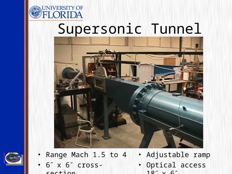
Supersonic Tunnel
• Range Mach 1.5 to 4
• 6x 6 cross-section
• Adjustable ramp
• Optical access 18x 6
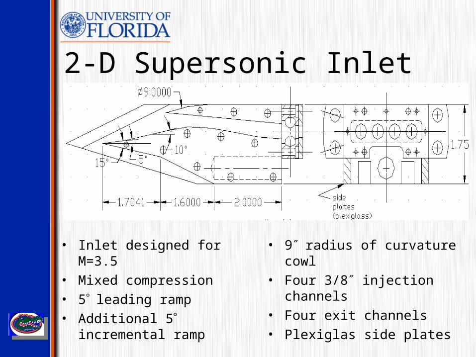
2-D Supersonic Inlet
• Inlet designed for M=3.5
• Mixed compression
• 5leading ramp
• Additional 5 incremental ramp
• 9radius of curvature cowl
• Four 3/8 injection channels
• Four exit channels
• Plexiglas side plates
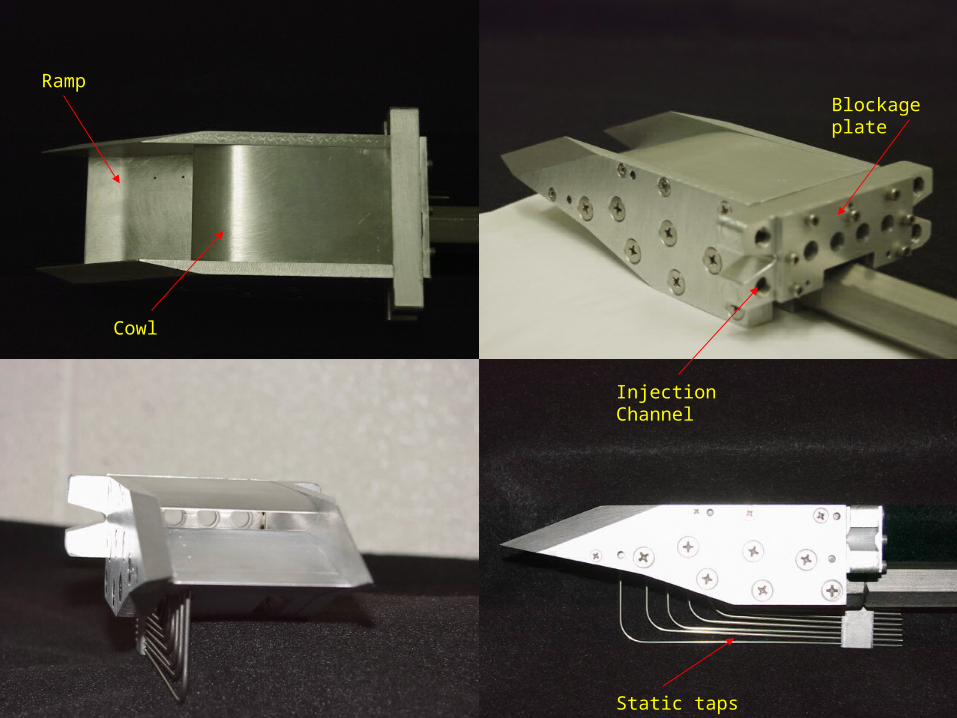
Cowl
Ramp
Static taps
Blockage plate
Injection Channel

Schlieren• Setup
– Mercury short arc lamp 100W/1 (3 electrodes)
– Collimating mirrors
– knife edge
– Power supply (C.C.)
• Flow visualization Tool
– Density gradients
• Shocks
• Oscillations
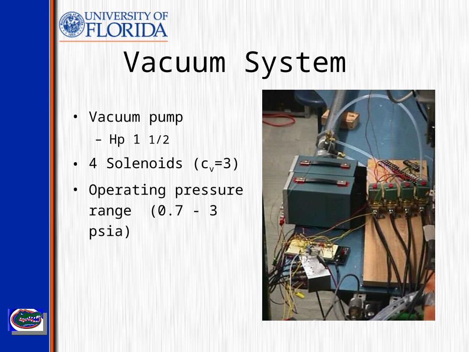
Vacuum System
• Vacuum pump
– Hp 1 1/2
• 4 Solenoids (cv=3)
• Operating pressure range
(0.7 - 3 psia)
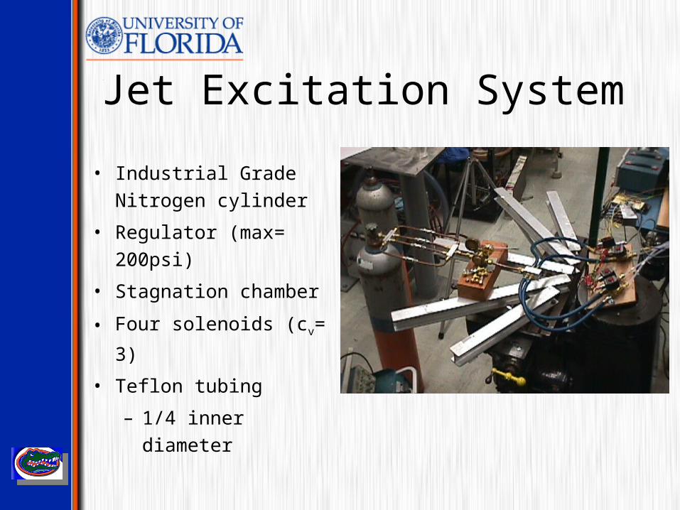
Jet Excitation System
• Industrial Grade Nitrogen
cylinder
• Regulator (max= 200psi)
• Stagnation chamber
• Four solenoids (cv= 3)
• Teflon tubing
– 1/4 inner diameter
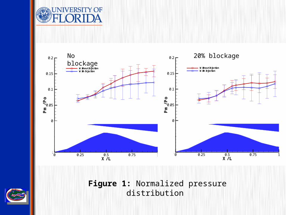
Figure 1: Normalized pressure distribution
X / L
Pm/Po
0 0.25 0.5 0.75 1-0.1
-0.05
0
0.05
0.1
0.15
0.2
Without InjectionWith Injection
X / L
Pm/Po
0 0.25 0.5 0.75 1-0.1
-0.05
0
0.05
0.1
0.15
0.2
Without InjectionWith Injection
No blockage 20% blockage
0
0.1
0.2
p/p 0
tap 1 0
0.1
0.2
p/p 0
tap 7
0
0.1
0.2p/
p 0
tap 2 0
0.1
0.2
p/p 0
tap 8
0
0.1
0.2
p/p 0
tap 3 0
0.1
0.2
p/p 0
tap 9
0
0.1
0.2
p/p 0
tap 4 0
0.1
0.2
p/p 0
tap 10
0
0.1
0.2
p/p 0
tap 522 22.2 22.4 22.6 22.8 23
0
0.1
0.2
p/p 0
tap 11
t (s)
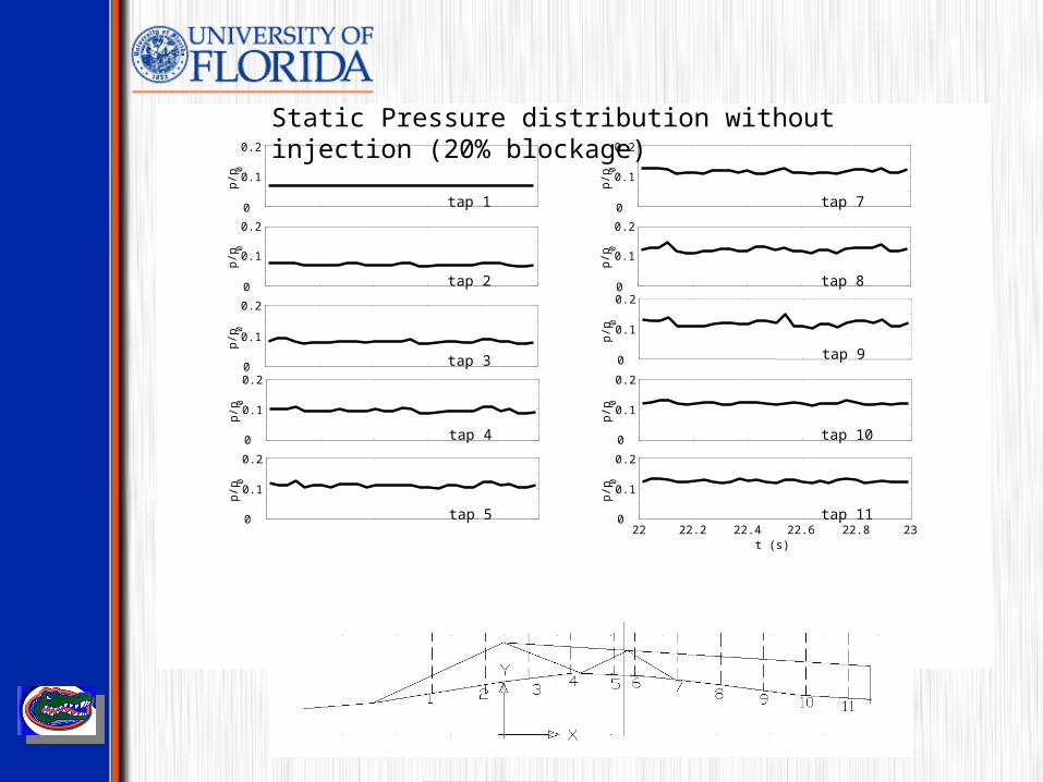
Static Pressure distribution without injection (20% blockage)
0
0.1
0.2
p/p 0
tap 1 0
0.1
0.2
p/p 0
tap 7
0
0.1
0.2p/
p 0
tap 2 0
0.1
0.2
p/p 0
tap 8
0
0.1
0.2
p/p 0
tap 30
0.1
0.2
p/p 0
tap 9
0
0.1
0.2
p/p 0
tap 4 0
0.1
0.2
p/p 0
tap 10
0
0.1
0.2
p/p 0
tap 519 19.2 19.4 19.6 19.8 20
0
0.1
0.2
p/p 0
tap 11
t (s)
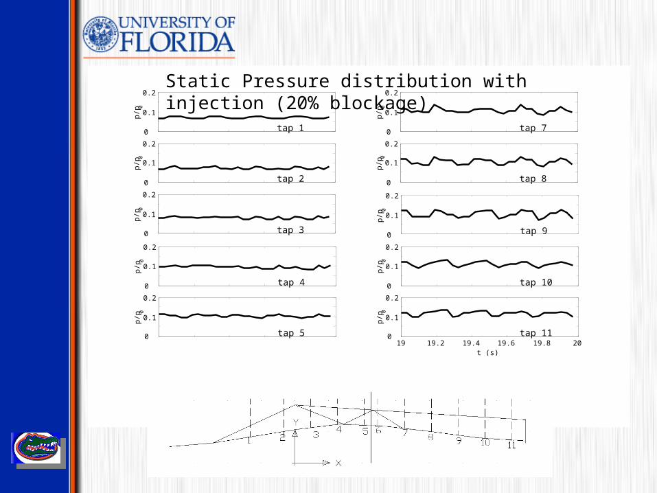
Static Pressure distribution with injection (20% blockage)
Effect of Excitation
• Pressure drop during air injection.
• Oscillations of equal frequency to the injection solenoids
were observed in the static taps.
• Lower frequencies produced larger oscillations in the flow.
• Greater exit area blockage lowered the pressure in the inlet.
• Injecting higher mass flow increased the oscillations.
• Coupling of solenoids also affected the flow oscillations.
Future Work
• Add additional static taps at the cowl surface to investigate if
any separation is occurring inside the inlet.
• Introduce a stagnation tap at the exit in order to have a better
understanding of the exit Mach number.
• If the inlet is supersonic as believed in the present, then further
modifications to the inlet must be made in order to create a
subsonic flow at the exit.
• Further modifications can also be made to the back body to
increase the pressure in the inlet.