Embed Size (px)
Citation preview

OFFICE OF STATEWIDE HEALTH PLANNING AND DEVELOPMENT FACILITIES DEVELOPMENT DIVISION
“Access to Safe, Quality Healthcare Environments that Meet California’s Diverse and Dynamic Needs”
STATE OF CALIFORNIA – HEALTH AND HUMAN SERVICES AGENCY OSH-FD-759 (REV 1/24/13) Page 1 of 3
APPLICATION FOR OSHPD SPECIAL SEISMIC CERTIFICATION PREAPPROVAL (OSP)
OFFICE USE ONLY
APPLICATION #: OSP – 0385 – 10
OSHPD Special Seismic Certification Preapproval (OSP)
Type: New Renewal
Manufacturer Information
Manufacturer: Johnson Controls, Inc.
Manufacturer’s Technical Representative: Timothy W. Irvin, Manager – Airside Commercial Application Support
Mailing Address: 631 S. Richland Avenue, Door 100 – MC 362A-D, York, PA 17403
Telephone: (414) 524-6211 Email: [email protected]
Product Information
Product Name: Blower Coils: ACB, ACR, AHI, AHM, AVI, AVM
Product Type: Mechanical equipment
Product Model Number: See Attachment (List all unique product identification numbers and/or part numbers)
General Description: Blower coil units containing coils, fans, motors, filters, dampers, electric heat and controls.
Seismic enhancements made to the test units required to address the anomalies observed during the tests shall be incorporated into the production units.
Mounting Description: Rigid base mount (ACB, ACR, AVI/AVM and AHI/AHM); ceiling suspended (AHI/AHM)
Applicant Information
Applicant Company Name: DYNAMIC CERTIFICATION LABORATORIES
Contact Person: JOSEPH L. LABRIE, S.E., MANAGING PARTNER
Mailing Address: 1315 GREG STREET, SUITE 109, SPARKS, NV 89431
Telephone: (775) 358-5085 Email: [email protected]
I hereby agree to reimburse the Office of Statewide Health Planning and Development review fees in accordance with the California Administrative Code, 2013.
Signature of Applicant: Date: 3/10/14 Title: MANAGING PARTNER Company Name: DYNAMIC CERTIFICATION LABORATORIES
03/12/2014 OSP-0385-10 Page 1 of 25

OFFICE OF STATEWIDE HEALTH PLANNING AND DEVELOPMENT FACILITIES DEVELOPMENT DIVISION
“Access to Safe, Quality Healthcare Environments that Meet California’s Diverse and Dynamic Needs”
California Licensed Structural Engineer Responsible for the Engineering and Test Report(s)
Company Name: DYNAMIC CERTIFICATION LABORATORIES
Name: DR. AHMAD ITANI, S.E. California License Number: SE-5220
Mailing Address: 1315 GREG STREET, SUITE 109, SPARKS, NV 89431
Telephone: (775) 358-5085 Email: [email protected]
Supports and Attachments Preapproval
Supports and attachments are preapproved under OPM- (Separate application for OSHPD Preapproval of Manufacturer’s Certification (OPM) of Supports and attachments is required)
Supports and attachments are not preapproved
Certification Method
Testing in accordance with: ICC-ES AC156
Other (Please Specify):
Testing Laboratory
Company Name: DYNAMIC CERTIFICATION LABORATORIES
Contact Name: AUSTIN BROWN, P.E., LABORATORY MANAGER
Mailing Address: 1315 GREG STREET, SUITE 109, SPARKS, NV 89431
Telephone: (775) 358-5085 Email: [email protected]
STATE OF CALIFORNIA – HEALTH AND HUMAN SERVICES AGENCY OSH-FD-759 (REV 1/24/13) Page 2 of 3
03/12/2014 OSP-0385-10 Page 2 of 25

OFFICE OF STATEWIDE HEALTH PLANNING AND DEVELOPMENT FACILITIES DEVELOPMENT DIVISION
“Access to Safe, Quality Healthcare Environments that Meet California’s Diverse and Dynamic Needs”
STATE OF CALIFORNIA – HEALTH AND HUMAN SERVICES AGENCY OSH-FD-759 (REV 1/24/13) Page 3 of 3
Seismic Parameters
Design in accordance with ASCE 7-10 Chapter 13: Yes No
Design Basis of Equipment or Components (Fp/Wp) = 1.44 (SDS 1.92); 1.45 (SDS 1.93); 1.50 (SDS 2.00)
SDS (Design spectral response acceleration at short period, g) = 1.92 (ACB, ACR); 1.93 (AVI, AHI); 2.00 (AHM)
ap (In-structure equipment or component amplification factor) = 2.5
Rp (Equipment or component response modification factor) = 6.0
Ω0 (System overstrength factor) = 2.5
Ip (Importance factor) = 1.5
z/h (Height factor ratio) = 1.0
Equipment or Component Natural Frequencies (Hz) = See attachments
Overall dimensions and weight (or range thereof) = See attachments
Equipment or Components @ grade designed in accordance with ASCE 7-10 Chapter 15: Yes No
Design Basis of Equipment or Components (V/W) =
SDS (Design spectral response acceleration at short period, g) =
SD1 (Design spectral response acceleration at 1 second period, g) =
R (Response modification coefficient ) =
Ω0 (System overstrength factor) =
Cd (Deflection amplification factor) =
Ip (Importance factor) = 1.5
Height to Center of Gravity above base =
Equipment or Component Natural Frequencies (Hz) =
Overall dimensions and weight (or range thereof) =
Tank(s) designed in accordance with ASME BPVC, 2010: Yes No
List of Attachments Supporting Special Seismic Certification
Test Report(s) Drawings Calculations Manufacturer’s Catalog
Other(s) (Please Specify):
OSHPD Approval (For Office Use Only) – Approval Expires on December 31, 2019
Signature: Date: 3/12/2014
Print Name: M. R. Karim Title: SHFR
Special Seismic Certification Valid Up to : SDS (g) = See Above z/h = 1.0
Condition of Approval (if applicable):
03/12/2014 OSP-0385-10 Page 3 of 25
Base Unit Length
Additional Length w/
Inlet Damper
WidthBase Unit
Height
Additional Height w/
Electric Heat
Additional Height w/
Return Plenum
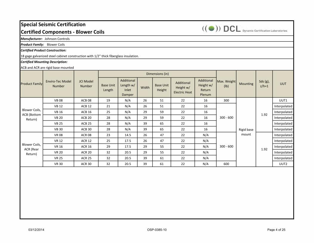
VB 08 ACB 08 19 N/A 26 51 22 16 300 UUT1
VB 12 ACB 12 21 N/A 26 51 22 16 Interpolated
VB 16 ACB 16 25 N/A 29 59 22 16 Interpolated
VB 20 ACB 20 28 N/A 29 59 22 16 Interpolated
VB 25 ACB 25 28 N/A 39 65 22 16 Interpolated
VB 30 ACB 30 28 N/A 39 65 22 16 Interpolated
VR 08 ACR 08 23 14.5 26 47 22 N/A Interpolated
VR 12 ACR 12 25 17.5 26 47 22 N/A Interpolated
VR 16 ACR 16 29 17.5 29 55 22 N/A Interpolated
VR 20 ACR 20 32 20.5 29 55 22 N/A Interpolated
VR 25 ACR 25 32 20.5 39 61 22 N/A Interpolated
VR 30 ACR 30 32 20.5 39 61 22 N/A 600 UUT2
Certified Mounting Description:
ACB and ACR are rigid base mounted
Product FamilyEnviro-Tec Model
NumberJCI Model Number
Max. Weight (lb)
MountingSds (g), z/h=1
18 gage galvanized steel cabinet construction with 1/2" thick fiberglass insulation.
Special Seismic Certification Certified Components - Blower Coils Manufacturer: Johnson Controls
Product Family: Blower Coils
Certified Product Construction:
Rigid base mount
300 - 600
300 - 600
UUT
Blower Coils, ACR (Rear
Return)1.92
Blower Coils, ACB (Bottom
Return)1.92
Dimensions (in)
03/12/2014 OSP-0385-10 Page 4 of 25

Length
Additional Length w/
Electric Heat Module
Width Height Max Length Width Height
V/VM 08 AVI/AVM 08 28 1/2 22 30 45 19 30 22 380 UUT3V/VM 12 AVI/AVM 12 28 1/2 22 36 45 19 36 22 InterpolatedV/VM 16 AVI/AVM 16 28 1/2 22 44 45 19 44 22 InterpolatedV/VM 20 AVI/AVM 20 34 1/2 22 50 51 22 50 22 InterpolatedV/VM 30 AVI/AVM 30 34 1/2 22 59 57 22 59 31 InterpolatedV/VM 40 AVI/AVM 40 34 1/2 22 68 60 24 68 31 950 UUT4H/HM 08 AHI/AHM 08 52 1/2 22 30 21 19 30 22 390 UUT31H/HM 12 AHI/AHM 12 52 1/2 22 36 21 19 36 22 InterpolatedH/HM 16 AHI/AHM 16 52 1/2 22 44 21 19 44 22 InterpolatedH/HM 20 AHI/AHM 20 52 1/2 22 50 21 22 50 22 InterpolatedH/HM 30 AHI/AHM 30 58 1/2 22 59 30 22 59 31 InterpolatedH/HM 40 AHI/AHM 40 58 1/2 22 68 30 24 68 31 970 UUT32H/HM 08 AHI/AHM 08 52 1/2 22 30 21 19 30 22 390 UUT27H/HM 12 AHI/AHM 12 52 1/2 22 36 21 19 36 22 InterpolatedH/HM 16 AHI/AHM 16 52 1/2 22 44 21 19 44 22 InterpolatedH/HM 20 AHI/AHM 20 52 1/2 22 50 21 22 50 22 InterpolatedH/HM 30 AHI/AHM 30 58 1/2 22 59 30 22 59 31 InterpolatedH/HM 40 AHI/AHM 40 58 1/2 22 68 30 24 68 31 970 UUT28
*M designates the presence of a mixing box
18 gage galvanized steel cabinet construction; 1" thick foil faced fiberglass insulation.
380 - 950
Special Seismic Certification Certified Components - Blower Coils Manufacturer: Johnson Controls
Product Family: Blower Coils
Certified Product Construction:
Certified Mounting Description:
AVI, AVM, AHI, AHM are rigid base mounted. AHI/AHM can also be ceiling suspended.
Product FamilyEnviro-Tec
Model NumberJCI Model Number
Cabinet Dimensions (in)Max.
Weight (lb)
MountingSds (g), z/h=1
UUT
2.00
Blower Coils, AHI / AHM*
Ceiling Suspended
1.93
Blower Coils, AVI / AVM*
Rigid base mount
1.93
Standard Mixing Box Dimensions (in)
390 - 970
390 - 970Blower Coils, AHI / AHM*
Rigid base mount
03/12/2014 OSP-0385-10 Page 5 of 25

Height Width8 JCI 16 30 2 6 1 12 UUT3
12 - 30 JCI 16 to 25 30 to 68 2 6 1 12 to 178 Interpolated40 JCI 25 68 2 6 1 178 UUT4
Coil Variables1. Fin Material: Aluminum2. Coil Casing: Galvanized Carbon Steel3. Fin Shape: Corrugated4. Tube diameter: 0.5"5. Tube thickness: 0.016", 0.025"6. Fins Per Inch: 12
Height Width8 JCI 16 30 2 6 1 12 UUT27
12 - 30 JCI 16 to 25 30 to 68 2 6 1 12 to 178 Interpolated40 JCI 25 68 2 6 1 178 UUT28
Coil Variables1. Fin Material: Aluminum2. Coil Casing: Galvanized Carbon Steel3. Fin Shape: Corrugated4. Tube diameter: 0.5"5. Tube thickness: 0.016", 0.025"6. Fins Per Inch: 12
1.93
Coils (H/AHI, HM/AHM) - Ceiling Suspended Units
Unit Size ManufacturerDimensions (in) Max Row Qty
(Heat)Max Row Qty
(Cool)Number of Coils,
StackedWeight (lb)
Sds (g), z/h=1
Unit
1.93
UnitUnit SizeDimensions (in) Max Row Qty
(Heat)Max Row Qty
(Cool)Number of Coils,
StackedWeight (lb)Manufacturer
Sds (g), z/h=1
Coils (V/AVI, VM/AVM) - Rigid Base-Mounted Units
Special Seismic Certification Certified SubcomponentsManufacturer: Johnson Controls, Inc.
Product Line: Blower Coils
Certified Subcomponent: Coils
03/12/2014 OSP-0385-10 Page 6 of 25

Height Width8 JCI 16 30 2 6 1 12 UUT31
12 - 30 JCI 16 to 25 30 to 68 2 6 1 12 to 178 Interpolated40 JCI 25 68 2 6 1 178 UUT32
Coil Variables1. Fin Material: Aluminum2. Coil Casing: Galvanized Carbon Steel3. Fin Shape: Corrugated4. Tube diameter: 0.5"5. Tube thickness: 0.016", 0.025"6. Fins Per Inch: 12
Height Width8 JCI 18.25 13.125 4 1 1 12 UUT 1
12 - 25 JCI 18.25 13.125 to 41.25 4 to 6 1 or 2 1 12 to 146 Interpolated30 JCI 18.25 41.25 6 2 1 146 UUT 2
Coil Variables1. Fin Material: Aluminum2. Coil Casing: Galvanized Carbon Steel3. Fin Shape: Corrugated4. Tube diameter: 0.5"5. Tube thickness: 0.016", 0.025"6. Fins Per Inch: 8 - 14
1.92
2.0
Special Seismic Certification Certified SubcomponentsManufacturer: Johnson Controls, Inc.
Coils (H/AHI, HM/AHM) - Rigid Base-Mounted Units
Unit Size ManufacturerDimensions (in) Max Row Qty
(Heat)Max Row Qty
(Cool)Number of Coils,
StackedWeight (lb)
Sds (g), z/h=1
Unit
Product Line: Blower CoilsCertified Subcomponent: Coils
Manufacturer
Coils (VB/ACB and VR/ACR) - Rigid Base-Mounted Units
Unit SizeDimensions (in)
Row Qty (Water) Row Qty (Steam)Number of Coils,
StackedWeight (lb) Unit
Sds (g), z/h=1
03/12/2014 OSP-0385-10 Page 7 of 25

Unit Size Manufacturer Shaft material Blade Material Fan Width (in) TypeNumber of
FansFan Wheel Diam. (in)
Weight (lb) Sds (g), z/h=1 Unit
8 8.25 1 9 27 UUT312 - 30 8.25 to 14.5 1 9 - 13 27 - 39 Interpolated
40 14.5 1 13 39 UUT4
Unit Size Manufacturer Shaft material Blade Material Fan Width (in) TypeNumber of
FansFan Wheel Diam. (in)
Weight (lb) Sds (g), z/h=1 Unit
8 8.25 1 9 27 UUT 2712 - 30 8.25 to 14.5 1 9 - 13 27 - 39 Interpolated
40 14.5 1 13 39 UUT 28
Unit Size Manufacturer Shaft material Blade Material Fan Width (in) TypeNumber of
FansFan Wheel Diam. (in)
Weight (lb) Sds (g), z/h=1 Unit
8 8.25 1 9 27 UUT 3112 - 30 8.25 to 14.5 1 9 - 13 27 - 39 Interpolated
40 14.5 1 13 39 UUT 32
Unit Size Manufacturer Shaft material Blade Material Fan Width (in) TypeNumber of
FansFan Wheel Diam. (in)
Weight (lb) Sds (g), z/h=1 Unit
8 8.25 1 9 10 UUT 112 - 25 8.25 to 13.25 1 9 10 - 17 Interpolated
30 13.25 1 9 17 UUT 2
Galvanized carbon steel
1.93
1.93
2.00
Galvanized carbon steel
Galvanized carbon steel
Galvanized carbon steel
Revcor
Fans (VB/ACB and VR/ACR) - Rigid Base-Mounted Units
DWDI, Forward Curve
DWDI, Forward Curve
Morrison Stainless steel
Stainless steel
Fans (H/AHI, HM/AHM) - Ceiling Suspended Units
Morrison Stainless steelDWDI, Forward
Curve
Fans (H/AHI, HM/AHM) - Rigid Base-Mounted Units
Morrison Stainless steelDWDI, Forward
Curve
1.92
Fans (V/AVI, VM/AVM) - Rigid Base-Mounted Units
Special Seismic Certification Certified SubcomponentsManufacturer: Johnson Controls, Inc.
Product Line: Blower Coils
Certified Subcomponent: Fans
03/12/2014 OSP-0385-10 Page 8 of 25

Unit Size Manufacturer Drive Tested VoltageCertified Voltage
HP Material Sds (g), z/h=1 Unit
8 Belt 208 1 Powder-coated carbon steel UUT3
12 - 30 Belt n/a 3/4 to 5 Powder-coated carbon steel Interpolated
40 Belt 460 5 Powder-coated carbon steel UUT4
Unit Size Manufacturer Drive Tested VoltageCertified Voltage
HP Material Sds (g), z/h=1 Unit
8 Belt 208 1 Powder-coated carbon steel UUT2712 - 30 Belt n/a 3/4 to 5 Powder-coated carbon steel Interpolated
40 Belt 460 5 Powder-coated carbon steel UUT28
Unit Size Manufacturer Drive Tested VoltageCertified Voltage
HP Material Sds (g), z/h=1 Unit
8 Belt 208 3/4 Powder-coated carbon steel UUT318 Belt 208 1 Powder-coated carbon steel Interpolated
12 - 30 Belt n/a 3/4 to 5 Powder-coated carbon steel Interpolated
40 Belt 460 5 Powder-coated carbon steel UUT32
Unit Size Manufacturer Drive Tested VoltageCertified Voltage
HP Material Sds (g), z/h=1 Unit
8 Belt 208 1 Powder-coated carbon steel UUT1
12 - 25 Belt n/a 1 to 1 1/2 Powder-coated carbon steel Interpolated
30 Belt 460 1 1/2 Powder-coated carbon steel UUT2
Special Seismic Certification Certified SubcomponentsManufacturer: Johnson Controls, Inc.
Product Line: Blower Coils
Certified Subcomponent: Motors
Weg 208 / 460
208 / 460
Fan Motors (V/AVI, VM/AVM) - Rigid Base-Mounted Units
Fan Motors (VB/ACB and VR/ACR) - Rigid Base-Mounted Units
Weg
Fan Motors (H/AHI, HM/AHM) - Ceiling Suspended Units
Weg 208 / 460
Fan Motors (H/AHI, HM/AHM) - Rigid Base-Mounted Units
Weg 208 / 460
1.93
1.93
2.0
1.92
03/12/2014 OSP-0385-10 Page 9 of 25

Unit Size Manufacturer Type Material Qty Height (in) Width (in)Filter Face
Area (sq. ft)Sds (g), z/h=1
Unit
8 AAF 2" Throwaway 1 16 20 2.2 UUT3
12 AAF 2" Throwaway 1 16 25 2.8 Interpolated16 AAF 2" Throwaway 2 16 20 4.4 Interpolated
2" Throwaway 1 16 202" Throwaway 1 16 252" Throwaway 2 16 252" Throwaway 1 20 25
40 AAF 2" Throwaway 3 20 25 10.4 UUT4
Unit Size Manufacturer Type Material Qty Height (in) Width (in)Filter Face
Area (sq. ft)Sds (g), z/h=1
Unit
8 AAF 2" Throwaway 1 16 20 2.2 UUT2712 AAF 2" Throwaway 1 16 25 2.8 Interpolated16 AAF 2" Throwaway 2 16 20 4.4 Interpolated
2" Throwaway 1 16 202" Throwaway 1 16 252" Throwaway 2 16 252" Throwaway 1 20 25
40 AAF 2" Throwaway 3 20 25 10.4 UUT28
Cotton-based fiber
Cotton-based fiber
1.93
1.9320 AAF 5.0 Interpolated
30 AAF 9.0 Interpolated
Special Seismic Certification Certified SubcomponentsManufacturer: Johnson Controls, Inc.
Product Line: Blower Coils
Certified Subcomponent: Filters
Filters (V/AVI, VM/AVM) - Rigid Base-Mounted Units
5.0
9.0
AAF
AAF
20
30
Interpolated
Interpolated
Filters (H/AHI, HM/AHM) - Ceiling Suspended Units
03/12/2014 OSP-0385-10 Page 10 of 25

Unit Size Manufacturer Type Material Qty Height (in) Width (in)Filter Face
Area (sq. ft)Sds (g), z/h=1
Unit
8 AAF 2" Throwaway 1 16 20 2.2 UUT3112 AAF 2" Throwaway 1 16 25 2.8 Interpolated16 AAF 2" Throwaway 2 16 20 4.4 Interpolated
2" Throwaway 1 16 202" Throwaway 1 16 252" Throwaway 2 16 252" Throwaway 1 20 25
40 AAF 2" Throwaway 3 20 25 10.4 UUT32
Unit Size Manufacturer Type Material Qty Height (in) Width (in)Filter Face
Area (sq. ft)Sds (g), z/h=1
Unit
8 AAF 2" Throwaway 1 16 20 2.2 UUT112 AAF 2" Throwaway 1 20 20 2.8 Interpolated16 AAF 2" Throwaway 1 24 24 4.0 Interpolated20 AAF 2" Throwaway 1 24 24 4.0 Interpolated
1 24 241 12 241 24 241 12 24
Cotton-based fiber
Cotton-based fiber
30 AAF 9.0 Interpolated
2.0
Special Seismic Certification Certified SubcomponentsManufacturer: Johnson Controls, Inc.
Product Line: Blower Coils
Certified Subcomponent: Filters
Filters (H/AHI, HM/AHM) - Rigid Base-Mounted Units
20 AAF 5.0 Interpolated
2" Throwaway
2" Throwaway
UUT2
Interpolated25
30 AAF
AAF 6.0
6.0
1.92
Filters (VB/ACB and VR/ACR) - Rigid Base-Mounted Units
03/12/2014 OSP-0385-10 Page 11 of 25

Unit Size Manufacturer Construction Qty Height (in) Width (in) Weight (lb) Sds (g), z/h=1 Unit
8 2 9 18 10 UUT312 2 9 24 Interpolated16 2 9 30 Interpolated20 2 12 36 Interpolated30 2 12 45 Interpolated40 2 15 48 15 UUT4
Unit Size Manufacturer Construction Qty Height (in) Width (in) Weight (lb) Sds (g), z/h=1 Unit
8 2 9 18 10 UUT2712 2 9 24 Interpolated16 2 9 30 Interpolated20 2 12 36 Interpolated30 2 12 45 Interpolated40 2 15 48 15 UUT28
Unit Size Manufacturer Construction Qty Height (in) Width (in) Weight (lb) Sds (g), z/h=1 Unit
8 2 9 18 10 UUT3112 2 9 24 Interpolated16 2 9 30 Interpolated20 2 12 36 Interpolated30 2 12 45 Interpolated40 2 15 48 15 UUT32
Dampers (V/AVI, VM/AVM) - Rigid Base-Mounted Units
JCI 14 gauge, galvanized steel 10 to 15
Dampers (H/AHI, HM/AHM) - Ceiling Suspended Units
JCI 14 gauge, galvanized steel 10 to 15
1.93
1.93
Special Seismic Certification Certified SubcomponentsManufacturer: Johnson Controls, Inc.
Product Line: Blower Coils
Certified Subcomponent: Dampers
Dampers (H/AHI, HM/AHM) - Rigid Base-Mounted Units
JCI 14 gauge, galvanized steel 2.010 to 15
03/12/2014 OSP-0385-10 Page 12 of 25

Model # Manufacturer Construction Qty Height (in) Width (in) Weight (lb) Sds (g), z/h=1 Unit
8 2 6 22 10 UUT112 2 9 22 Interpolated16 2 9 25 Interpolated20 2 12 25 Interpolated25 2 12 35 Interpolated30 2 12 35 15 UUT2
Dampers (VB/ACB and VR/ACR) - Rigid Base-Mounted Units
JCI 14 gauge, galvanized steel 10 to 15 1.92
Special Seismic Certification Certified SubcomponentsManufacturer: Johnson Controls, Inc.
Product Line: Blower Coils
Certified Subcomponent: Dampers
03/12/2014 OSP-0385-10 Page 13 of 25

Unit Size Manufacturer Construction Qty kW Output Voltage Sds (g), z/h=1 Test Unit
8 1 5 208 UUT312 - 30 1 5 - 26 208 - 460 Interpolated
40 1 26 460 UUT4
Unit Size Manufacturer Construction Qty kW Output Voltage Sds (g), z/h=1 Test Unit
8 1 5 208 UUT2712 - 30 1 5 - 26 208 - 460 Interpolated
40 1 26 460 UUT28
Unit Size Manufacturer Construction Qty kW Output Voltage Sds (g), z/h=1 Test Unit
8 1 5 208 UUT3112 - 30 1 5 - 26 208 - 460 Interpolated
40 1 26 460 UUT32
Unit Size Manufacturer Construction Qty kW Output Voltage Sds (g), z/h=1 Test Unit
8 1 5 208 UUT 112 - 25 1 5 - 18 208 - 460 Interpolated
30 1 18 460 UUT 2
Stainless steel frame, galvanized steel plates, internal wiring rated at 105°C
Stainless steel frame, galvanized steel plates, internal wiring rated at 105°C
Electric Heat (VB/ACB and VR/ACR) - Rigid Base-Mounted Units
JCI
Electric Heat (V/AVI, VM/AVM) - Rigid Base-Mounted Units
JCI
Electric Heat (H/AHI, HM/AHM) - Ceiling Suspended Units
JCIStainless steel frame, galvanized steel plates,
internal wiring rated at 105°C
Electric Heat (H/AHI, HM/AHM) - Rigid Base-Mounted Units
JCIStainless steel frame, galvanized steel plates,
internal wiring rated at 105°C
1.93
1.93
2
1.92
Special Seismic Certification Certified SubcomponentsManufacturer: Johnson Controls, Inc.
Product Line: Blower Coils
Certified Subcomponent: Electric Heat
03/12/2014 OSP-0385-10 Page 14 of 25

Model Manufacturer Description Material Sds (g), z/h=1 Unit
DFS-221-198 Cleveland Controls Airflow Switch Stainless steel housing 2.0 UUT31, UUT32
PE-01-0025 Square D Switch,3POS, CAM 480V 10A KS46B Plastic cover 2.0 UUT31, UUT32
PE-01-0026 Square D Switch, NONC CONTACT KA1 Plastic cover 2.0 UUT31, UUT32
OT40 ABB Disconnect switch, 3P 40A 600V Plastic cover 1.92 UUT1, UUT2, UUT31
OT80 ABB Disconnect switch, 3P 80A 600V Plastic cover 1.93 UUT4, UUT28, UUT32
PE-03-3091 Sprecher & Schuh Starter, 9A 3POLE 24V Plastic cover 1.93 UUT4, UUT28, UUT32
PE-05-1501 Hartland Contactor, 1P 50A 24VAC 9VA 1HP Silver cadmium oxide contacts 1.93 UUT4, UUT28, UUT32
PE-05-3351 Hartland Contactor, 3P 35A 24VAC 11VA 5HP Silver cadmium oxide contacts 1.93 UUT2, UUT4, UUT28, UUT32
PE-10-6107 Hartland Transformer (208/240)/24VAC 75VA 130deg C Class B insulation 1.93 UUT3, UUT31
PE-10-7107 Hartland Transformer 480/24VAC 75VA 130deg C Class B insulation 1.93 UUT4, UUT28, UUT32
PH-05-0012 Honeywell 2 1/2 Pitot tube Stainless steel 2.0 UUT31, UUT32
Certified Subcomponent: Controls
Controls
Special Seismic Certification Certified SubcomponentsManufacturer: Johnson Controls, Inc.
Product Line: Blower Coils
03/12/2014 OSP-0385-10 Page 15 of 25

Length Width Height Length Width Height Length Width Height
ACB 08 19 26 67* 18 7/8 26 22 N/A N/A N/A 300 1.93 UUT1
ACR 30 52.5* 39 61 25 5/8 39 22 N/A N/A N/A 600 1.92 UUT2
AVM 08 28 1/2 30 45 22 8 7/8 11 7/8 19 30 22 380 2.50 UUT3
AVM 40 34 1/2 68 60 22 15 5/8 16 5/8 24 68 31 950 1.93 UUT4
AHM 08 52 1/2 30 21 22 8 7/8 11 7/8 19 30 22 390 1.93 UUT27
AHM 40 58 1/2 68 30 22 15 5/8 16 5/8 24 68 31 970 1.93 UUT28
AHM 08 52 1/2 30 21 22 8 7/8 11 7/8 19 30 22 390 2.50 UUT31
AHM 40 58 1/2 68 30 22 15 5/8 16 5/8 24 68 31 970 2.00 UUT32*UUT1, height includes 16" for return plenum. UUT2, length includes 20.5" for inlet damper.
Rigid base mount
ACB, ACR, AVM and AHM are rigid base mounted; AHM are also ceiling suspended
Tested Mounting Description:
18 gage galvanized steel cabinet construction.
Rigid base mount
Ceiling Suspended
Dimensions (in)Model
Weight (lb)
MountingSds (g), z/h=1
Special Seismic Certification Tested Components - Blower Coils
Standard Mixing BoxElectric Heat ModuleMain Cabinet
Manufacturer: Johnson Controls
Tested Product Construction:
Product Family: Blower Coils
Unit
03/12/2014 OSP-0385-10 Page 16 of 25
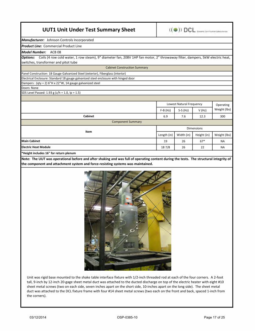
Manufacturer: Johnson Controls Incorporated
Product Line: Commercial Product Line
Model Number: ACB 08
F-B (Hz) S-S (Hz) V (Hz)
6.9 7.6 12.3 300
Length (in) Width (in) Height (in) Weight (lbs)
19 26 67* NA
18 7/8 26 22 NA
Lowest Natural Frequency Operating Weight (lbs)
UUT1 Unit Under Test Summary Sheet
Doors: None
Electrical Enclosure: Standard 18 gauge galvanized steel enclosure with hinged door
Cabinet Construction Summary
Panel Construction: 18 Gauge Galvanized Steel (exterior), Fiberglass (interior)
Dampers : (qty = 2) 6"H x 22"W, 14 gauge galvanized steel
Options: Coils (4 row cold water, 1 row steam), 9" diameter fan, 208V 1HP fan motor, 2" throwaway filter, dampers, 5kW electric heat, switches, transformer and pitot tube
SDS Level Passed: 1.93 g (z/h = 1.0, Ip = 1.5)
Component Summary
Dimensions
Main Cabinet
Cabinet
Note: The UUT was operational before and after shaking and was full of operating content during the tests. The structural integrity of the component and attachment system and force-resisting systems was maintained.
Item
Electric Heat Module
*Height includes 16" for return plenum
Unit was rigid base mounted to the shake table interface fixture with 1/2-inch threaded rod at each of the four corners. A 2-foot tall, 9-inch by 12-inch 20-gage sheet metal duct was attached to the ducted discharge on top of the electric heater with eight #10 sheet metal screws (two on each side, seven inches apart on the short side, 10-inches apart on the long side). The sheet metal duct was attached to the DCL fixture frame with four #14 sheet metal screws (two each on the front and back, spaced 1-inch from the corners).
03/12/2014 OSP-0385-10 Page 17 of 25

Manufacturer: Johnson Controls Incorporated
Product Line: Commercial Product Line
Model Number: ACR 30
F-B (Hz) S-S (Hz) V (Hz)
8.7 8.2 17.5 600
Length (in) Width (in) Height (in) Weight (lbs)
52 1/2* 39 61 NA
25 5/8 39 22 NA
Dimensions
Main Cabinet
Options: Coils (6 row cold water, 2 row steam), 9" diameter fan, 460V 1.5HP fan motor, 2" throwaway filters, dampers, 18kW electric heat, switches, transformer and pitot tube
Item
*Length includes 20.5" for inlet damper
UUT2 Unit Under Test Summary Sheet
Cabinet Construction Summary
Panel Construction: 18 Gauge Galvanized Steel (exterior), Fiberglass (interior)
Electrical Enclosure: Standard 18 gauge galvanized steel enclosure with hinged door
Dampers : (qty=2) 12"H x 35"W, 14 gauge galvanized steel
Doors: None
SDS Level Passed: 1.92 g (z/h = 1.0, Ip = 1.5)
Lowest Natural Frequency Operating Weight (lbs)
Component Summary
Electric Heat Module
Cabinet
Note: The UUT was operational before and after shaking and was full of operating content during the tests. The structural integrity of the component and attachment system and force-resisting systems was maintained.
Unit was rigid base mounted to the shake table interface fixture with 1/2-inch threaded rod at each of the four corners. A 2-foot tall, 16-inch by 17-inch 20-gage sheet metal duct was attached to the ducted discharge on top of the electric heater with eight #10 sheet metal screws (two on each side, seven inches apart on the short side, 10-inches apart on the long side). The sheet metal duct was attached to the DCL fixture frame with four #14 sheet metal screws (two each on the front and back, spaced 1-inch from the corners).
03/12/2014 OSP-0385-10 Page 18 of 25

Manufacturer: Johnson Controls Incorporated
Product Line: Commercial Product Line
Model Number: AVM 08
F-B (Hz) S-S (Hz) V (Hz)
10.9 11.9 16.5 380
Length (in) Width (in) Height (in) Weight (lbs)
28 1/2 30 45 NA
22 8 7/8 11 7/8 NA
19 30 22 NA
Main Cabinet
Electric Heat Module
Standard Mixing BoxNote: The UUT was operational before and after shaking and was full of operating content during the tests. The structural integrity of the component and attachment system and force-resisting systems was maintained.
DimensionsItem
UUT3 Unit Under Test Summary Sheet
Cabinet Construction Summary
Panel Construction: 18 Gauge Galvanized Steel (exterior), Fiberglass (interior)
Electrical Enclosure: Standard 18 gauge galvanized steel enclosure with hinged door
Dampers : (qty=2) 9"H x 18"W, 14 gauge galvanized steel
Options: Coils (2 row heating, 6 row cooling), 9" diameter fan, 208V 1HP fan motor, 2" throwaway filter, dampers, 5kW electric heat, switches, transformer and pitot tube
Component Summary
Doors: None
SDS Level Passed: 2.5 g (z/h = 1.0, Ip = 1.5)
Lowest Natural Frequency Operating Weight (lbs)
Cabinet
Unit was rigid base mounted to the shake table interface fixture with 1/2-inch threaded rod at each of the four corners.
03/12/2014 OSP-0385-10 Page 19 of 25

Manufacturer: Johnson Controls Incorporated
Product Line: Commercial Product Line
Model Number: AVM 40
F-B (Hz) S-S (Hz) V (Hz)
6.1 12.1 12 950
Length (in) Width (in) Height (in) Weight (lbs)
34 1/2 68 60 NA
22 15 5/8 16 5/8 NA
24 68 31 NA
UUT4 Unit Under Test Summary Sheet
Cabinet Construction Summary
Panel Construction: 18 Gauge Galvanized Steel (exterior), Fiberglass (interior)
Electrical Enclosure: Standard 18 gauge galvanized steel enclosure with hinged door
Dampers : (qty=2) 15"H x 48"W, 14 gauge galvanized steel
Options: Coils (2 row heating, 6 row cooling), 13" diameter fan, 460V 5HP fan motor, 2" throwaway filters, dampers, 26kW electric heat, switches, transformer and pitot tube
Doors: None
SDS Level Passed: 1.93 g (z/h = 1.0, Ip = 1.5)
Lowest Natural Frequency Operating Weight (lbs)
CabinetComponent Summary
Dimensions
Main Cabinet
Note: The UUT was operational before and after shaking and was full of operating content during the tests. The structural integrity of the component and attachment system and force-resisting systems was maintained.
Electric Heat Module
Standard Mixing Box
Item
Unit was rigid base mounted to the shake table interface fixture with 1/2-inch threaded rod at each of the four corners.
03/12/2014 OSP-0385-10 Page 20 of 25

Manufacturer: Johnson Controls IncorporatedProduct Line: Commercial Product LineModel Number: AHM 08
F-B (Hz) S-S (Hz) V (Hz)N/A N/A N/A 390
Length (in) Width (in) Height (in) Weight (lb)52 1/2 30 21 NA
22 8 7/8 11 7/8 NA19 30 22 NA
Main Cabinet
Standard Mixing Box
Item
Note: The UUT was operational before and after shaking and was full of operating content during the tests. The structural integrity of the component and attachment system and force-resisting systems was maintained.
Cabinet
Options: Coils (2 row heating coils, 6 row cooling coils), 9" diameter fan, 208V 1HP fan motor, 2" throwaway filter, dampers and 5kW electric heat
UUT27 Unit Under Test Summary Sheet
Cabinet Construction SummaryPanel Construction: 18 Gauge Galvanized Steel (exterior), Fiberglass (interior)Electrical Enclosure: Standard 18 gauge galvanized steel enclosure with hinged doorDampers : (qty=2) 9"H x 18"W, 14 gauge galvanized steelDoors: NoneSDS Level Passed: 1.93 g (z/h = 1.0, Ip = 1.5)
Lowest Natural Frequency Operating Weight (lb)
Component Summary
Electric Heat Module
Dimensions
Unit was ceiling suspended using strut screwed to the top and bottom of the unit (front and back) using #12 sheet metal screws, spaced approximatley 6-inches on center. On the top of each of the four corners, (4) 90 deg. 16 gage galvanized steel brackets were attached on the side and 4 flat 16 gage galvanized steel brackets on the top of each corner. Each flat bracket overlaps the 90 deg. bracket, and a 1/2" threaded rod is attached through each and up into the fixture frame. Each threaded rod is stiffened using a length of unistrut and B-line 1/2-inch clips, spaced no more than 22 inches on center. Lateral bracing accomplished using 14 gage 45 degree brackets provided by JCI, 3/16" cable with 4 saddle clamps per cable (2 saddle clamps at each connection).
03/12/2014 OSP-0385-10 Page 21 of 25

Manufacturer: Johnson Controls IncorporatedProduct Line: Commercial Product LineModel Number: AHM 40
F-B (Hz) S-S (Hz) V (Hz)N/A N/A N/A 970
Length (in) Width (in) Height (in) Weight (lb)58 1/2 68 30 NA
22 15 5/8 16 5/8 NA24 68 31 NA
Note: The UUT was operational before and after shaking and was full of operating content during the tests. The structural integrity of the component and attachment system and force-resisting systems was maintained.
UUT28 Unit Under Test Summary Sheet
Cabinet Construction SummaryPanel Construction: 18 Gauge Galvanized Steel (exterior), Fiberglass (interior)Electrical Enclosure: Standard 18 gauge galvanized steel enclosure with hinged doorDampers : (qty=2) 15"H x 48"W, 14 gauge galvanized steelDoors: NoneSDS Level Passed: 1.93 g (z/h = 1.0, Ip = 1.5)
Lowest Natural Frequency Operating Weight (lb)
Component Summary
Options: Coils (2 row heating, 6 row cooling), 13" diameter fan, 460V 5HP fan motor, 2" throwaway filters, dampers, 26kW electric heat, switches, transformer and pitot tube
Dimensions
Main CabinetElectric Heat ModuleStandard Mixing Box
Item
Cabinet
03/12/2014 OSP-0385-10 Page 22 of 25

Manufacturer: Johnson Controls Incorporated
Product Line: Commercial Product Line
Model Number: AHM 40
Seismic Design Kit:
Mounting Description:
Unit was ceiling suspended using solid 12 gage 1-5/8-inch strut screwed to the top of the unit with #14 sheet metal screws, spaced approximatley 3-inches on center. 5/8-inch Grade 2 threaded rod was attached through the manufacturer-provided gage steel channel on the bottom of the unit and the solid strut screwed to the top of the unit (see bottom-left photo). The approximate length of the threaded rod between the top of the unit and the DCL steel fixture frame was 10-1/2-inches (nut to nut) as shown in the bottom-right photo). The unit was braced using 45 degree 1/4-inch thick galvanized steel outside angle brackets for strut channel and 3/8-inch diameter general purpose cable (6 x 19 Class IWRC) with 4 saddle clips per cable (2 clips at each connection). Each bracket was attached to the DCL steel fixture frame using a 1/2-inch Grade 5 bolt. The brackets attached to the solid strut at the top of the unit were sandwiched between one 3-inch square 1/4-inch thick plate washer on the bottom and two 4-inch square 1/4-inch thick plate washers on the top as shown in the photo on the bottom-right.
The mixing box to coil section connection was reinforced using solid 12 gage 1-5/8-inch strut bolted to each section using three 1/4" hex cap bolts per section per length of strut. Two 14-inch lengths of strut were used per top side for a total of four lengths of strut.
UUT28 Unit Under Test Summary Sheet (Continued)
03/12/2014 OSP-0385-10 Page 23 of 25

Manufacturer: Johnson Controls Incorporated
Product Line: Commercial Product Line
Model Number: AHM 08
F-B (Hz) S-S (Hz) V (Hz)
26.3 28.0 27.8 390
Length (in) Width (in) Height (in) Weight (lbs)
52 1/2 30 21 NA
22 8 7/8 11 7/8 NA
19 30 22 NA
Component Summary
UUT31 Unit Under Test Summary Sheet
Cabinet Construction Summary
Panel Construction: 18 Gauge Galvanized Steel (exterior), Fiberglass (interior)
Electrical Enclosure: Standard 18 gauge galvanized steel enclosure with hinged door
Doors: None
SDS Level Passed: 2.5 g (z/h = 1.0, Ip = 1.5)
Lowest Natural Frequency Operating Weight (lbs)
Options: Coils (2 row heating, 6 row cooling), 9" diameter fan, 208V 3/4HP fan motor, 2" throwaway filter, dampers, 5kW electric heat, switches, transformer and pitot tube
Cabinet
Dampers : (qty=2) 9"H x 18"W, 14 gauge galvanized steel
Dimensions
Main Cabinet
Electric Heat Module
Standard Mixing Box
Item
Note: The UUT was operational before and after shaking and was full of operating content during the tests. The structural integrity of the component and attachment system and force-resisting systems was maintained.
Unit was rigid base mounted to the shake table interface fixture four 1/2-inch diameter Grade 5 bolts, one on each corner of the unit, using the manufacturer-provided mounting tabs.
03/12/2014 OSP-0385-10 Page 24 of 25

Manufacturer: Johnson Controls Incorporated
Product Line: Commercial Product Line
Model Number: AHM 40
F-B (Hz) S-S (Hz) V (Hz)
12.3 18.5 15.8 970
Length (in) Width (in) Height (in) Weight (lbs)
58 1/2 68 30 NA
22 15 5/8 16 5/8 NA
24 68 31 NA
Component Summary
UUT32 Unit Under Test Summary Sheet
Cabinet Construction Summary
Panel Construction: 18 Gauge Galvanized Steel (exterior), Fiberglass (interior)
Electrical Enclosure: Standard 18 gauge galvanized steel enclosure with hinged door
Doors: None
SDS Level Passed: 2.0 g (z/h = 1.0, Ip = 1.5)
Lowest Natural Frequency Operating Weight (lbs)
Options: Coils (2 row heating, 6 row cooling), 13" diameter fan, 460V 5HP fan motor, 2" throwaway filters, dampers, 26kW electric heat, switches, transformer and pitot tube
Cabinet
Dampers : (qty=2) 15"H x 48"W, 14 gauge galvanized steel
Main Cabinet
Electric Heat Module
Standard Mixing Box
Item
Note: The UUT was operational before and after shaking and was full of operating content during the tests. The structural integrity of the component and attachment system and force-resisting systems was maintained.
Dimensions
Unit was rigid base mounted to the shake table interface fixture four 1/2-inch diameter Grade 5 bolts, one on each corner of the unit, using the manufacturer-provided mounting tabs.
03/12/2014 OSP-0385-10 Page 25 of 25


![OSHPD Special Seismic Certification Preapproval(SOP)...Description Mfr/Model Input1Voltage Output1Rating1Range1 [Voltage/Current/ Power] UUT Operator1Interface1 (Main1Controller) Dynaview1CH530](https://img.pdfslide.net/doc/110x75/6011d84aa57bcb7fdb3502dc/oshpd-special-seismic-certification-preapprovalsop-description-mfrmodel-input1voltage.jpg)