Embed Size (px)
Citation preview

Svensk Kärnbränslehantering ABSwedish Nuclear Fueland Waste Management CoBox 250, SE-101 24 Stockholm Tel +46 8 459 84 00
P-07-221
Oskarshamn site investigation
Drilling of cored borehole KLX17A
Henrik Ask, H Ask Geokonsult AB
Mansueto Morosini, Svensk Kärnbränslehantering AB
Liselotte Tiberg, Studsvik Nuclear AB
December 2007
CM
Gru
ppen
AB
, Bro
mm
a, 2
008
P-07-221

Tänd ett lager:
P, R eller TR.
Oskarshamn site investigation
Drilling of cored borehole KLX17A
Henrik Ask, H Ask Geokonsult AB
Mansueto Morosini, Svensk Kärnbränslehantering AB
Liselotte Tiberg, Studsvik Nuclear AB
December 2007
ISSN 1651-4416
SKB P-07-221
Keywords: Core drilling, Bedrock, Measurement while drilling, Flushing water monitoring, Water sampling, Wireline measurements, Air-lift pumping, Telescope hole.
Data in SKB’s database can be changed for different reasons. Minor changes in SKB’s database will not necessarily result in a revised report. Data revisions may also be presented as supplements, available at www.skb.se.
A pdf version of this document can be downloaded from www.skb.se.

3
Abstract
Borehole KLX17A is located in the Laxemar subarea. Drilling was made between August and October 2006 as a part of the site investigation for a possible repository for spent nuclear fuel in Oskarshamn municipality, Sweden. KLX17A was the eighteenth deep cored borehole within the site investigation in Oskarshamn.
KLX17A was core drilled to a length of 701.08 metres with N-size (76 mm) equipment. The uppermost section, to the length of 65.42 metres, was constructed as a telescopic borehole with an inner nominal diameter of 200 mm.
No water inflow could be measured over the entire length of the telescopic section after percussion drilling of the pilot borehole (nominal diameter 165 mm).
Seven successful tests were completed with wireline equipment in KLX17A from eleven attempts at various intervals. The resulting transmissivities (TM) varied between 2.5×10⁻⁵ and 1.1×10⁻⁷ m2/s. The most transmissive section was between 392 and 431 metres.
Continuous monitoring of drilling parameters and flushing water parameters with the drilling monitoring system was conducted throughout the core drilling phase in KLX17A.
Two water samples for chemical analysis were collected during the core drilling of KLX17A.
The air-lift pumping test in the telescopic section performed when borehole KLX17A was core drilled to its full length gave a transmissivity (TM) of 3.3×10⁻⁵ m2/s.
A total of 60 core samples with length of 0.3 to 0.5 metres were collected in KLX17A for analysis of pore water chemistry in the rock matrix (“pore matrix sampling”). The vast majority of the samples, 55 of 60, were taken in a campaign between 112 and 134 metres drilled length. The sampling was done immediately after drilling and unloading of the core barrel.
Lithologically the core is dominated Ävrö granite with intercalations of diorite/gabbro and fine-grained diorite-gabbro. Minor amounts of fine grained granite were also noted in the borehole.
Rock alteration is mostly weak. A section with significant red staining and increased frequency of fractures was logged from 100 to 120 m.
The average fracture frequency over the core drilled section is 1.7 (fractures/metre) expressed as open fractures.

4
Sammanfattning
Borrhål KLX17A ligger inom delområde Laxemar. Borrningen utfördes mellan augusti och oktober 2006 som ett led i platsundersökningen för ett möjligt djupförvar för använt kärnbränsle i Oskarshamns kommun. KLX17A var det artonde djupa kärnborrhålet inom platsundersökningen i Oskarshamn.
KLX17A kärnborrades med borrstorlek N (76 mm) till 701,08 meters borrad längd. Den övre delen av hålet, från markytan till 65,42 meter, utfördes som en teleskopdel med ca 200 mm inre diameter.
Inget vatteninflöde kunde uppmätas över hela teleskopdelen vid hammarborrningen av pilotdelen (nominell diameter 165 mm).
Sju stycken lyckade pumptester slutfördes med wireline-baserad mätutrustning från elva försök på varierande nivåer. De uppmätta transmissiviteterna (TM) varierade mellan 2,5×10⁻⁵ och 1,1×10⁻⁷ m2/s. Den mest transmissiva sektionen var mellan 392 och 431 meter.
Kontinuerliga mätningar av borrningsparametrar och spolvattenparametrar via DMS (Drilling Monitoring System) gjordes under hela kärnborrningsfasen i KLX17A.
Två vattenprover för kemisk analysering togs i samband med borrning i KLX17A.
Mammutpumpningen i teleskopdelen som gjordes när kärnborrningen i KLX17A utförts till full längd gav en transmissivitet (TM) på 3,3×10⁻⁵ m2/s.
Provtagning för analys av porvatten inne i bergmassan gjordes på flera ställen i KLX17A.
Totalt togs 60 stycken kärnprov med en längd på mellan 0,3 och 0,5 meter i KLX17A för analys av porvattenkemi inne i bergmassan (”pormatrix provtagning”). Den överväldigande andelen av proverna, 55 av 60, togs i en kampanj mellan 112 och 134 m borrad längd. Det intensivt provtagna intervallet sammanfaller i stort med läget på deformationszon EW900. Provtagningen gjordes omedelbart efter borrning och upptag av borrkärnan.
Litologiskt domineras kärnan av Ävrögranit med inslag av finkornig diorit-gabbro och diorit/gabbro. Mindre mängder av finkornig granit har också noterats i borrhålet.
Bergartsomvandling är oftast svag. Ett parti med betydande rödfärgning och förhöjd sprick-frekvens har karterats från 100 till 120 m.
Den genomsnittliga sprickfrekvensen i det kärnborrade partiet är 1,7 (sprickor/meter) uttryckt som öppna sprickor.

5
Contents
1 Introduction 7
2 Objective and scope 9
3 Overview of the drilling method 113.1 The SKB telescope drilling method 11
3.1.1 The flushing water system 123.2 Measurements and sampling during drilling 13
3.2.1 Percussion drilling 133.2.2 Core drilling 13
4 Contractors and equipment 154.1 Contractors 154.2 Percussion drilling equipment 164.3 Core drilling equipment 16
4.3.1 Measurements with wireline probe 164.3.2 Drilling monitoring system 174.3.3 Deviation measurements 184.3.4 Equipment for reaming reference slots 18
5 Execution and results 195.1 Summary of KLX17A drilling 195.2 Drilling, measurements and results in the telescopic section 0–65.42 m 22
5.2.1 Preparations 225.2.2 Drilling and casing installation 225.2.3 Measurements and sampling during drilling of the telescopic
section 235.2.4 Hydrogeological measurements and results during percussion
drilling 245.3 Core drilling KLX17A 65.42–701.08 m 24
5.3.1 Preparations 245.3.2 Flushing and return water handling 255.3.3 Drilling and deviation measurements KLX17A 255.3.4 Borehole wall risk assessment, stabilisation and completion 28
5.4 Hydrogeological and hydrochemical measurements and results 65.42–701.08 m. 305.4.1 Hydrogeological results from wireline measurements 305.4.2 Hydrochemistry 325.4.3 Results from air-lift pumping with evaluation of drawdown
and/or recovery 365.4.4 Hydraulic responses in near-by boreholes. 36
5.5 Drilling monitoring results 445.5.1 Drill monitoring system – DMS 445.5.2 Measurements of flushing water and drill cuttings 47
5.6 Geology 485.7 Data handling 485.8 Environmental control 48
5.8.1 Consumption of oil and chemicals 515.9 Nonconformities 51
6 References 53

6
Appendix 1 Geology and MWD parameters KLX17A 55Appendix 2 Chemical results 59Appendix 3 Chemistry – analytical method and quality 61Appendix 4 Deviation measurements 63Appendix 5 Wireline pumping tests in KLX17A 65Appendix 6 Technical data from environmental monitoring wells
SSM000252 and SSM000253 73

7
1 Introduction
SKB, the Swedish Nuclear Fuel & Waste Management Company, performs site investigations in order to evaluate the feasibility of locating a deep repository for spent nuclear fuel /1, 2/. The investigations are performed in two Swedish municipalities: Östhammar and Oskarshamn. Borehole KLX17A is located in the western part of the Laxemar subarea of the investigation area in Oskarshamn.
Drilling and investigations in boreholes are fundamental activities in order to facilitate charac-terisation of rock and groundwater properties at depth. KLX17A was the eighteenth deep cored borehole within the Oskarshamn site investigation. The location of the core drilled borehole and the water source, HLX14 in the Laxemar subarea is shown in Figure 1-1.
The drilling of KLX17A and all related on-site operations were performed according to a specific Activity Plan (AP PS 400-06-073), which in turn refers to a number of Method Descriptions, see Table 1-1.
The Activity Plans and Method Descriptions are SKB internal documents.
Figure 1-1. Location of the cored borehole KLX17A and the water source, percussion borehole HLX14 in the Laxemar subarea.

8
Table 1‑1. Controlling documents for the performance of the activity.
Activity Plan Number VersionKärnborrning KLX17A AP PS 400-06-073 1.0*
Method Descriptions Number VersionMetodbeskrivning för kärnborrning SKB MD 620.003 2.0Metodbeskrivning för hammarborrning SKB MD 610.003 3.0Metodbeskrivning för hydrauliska enhålstrester SKB MD 321.003 1.0Metodbeskrivning för registrering och provtagning av spolvattenparametrar samt borrkax under kärnborrning
SKB MD 640.001 1.0
Metodbeskrivning för vattenprovtagning, pumptest och tryckmätning i samband med wireline-borrning
SKB MD 321.002 1.0
Instruktion för rengöring av borrhålsutrustning och viss markbaserad utrustning
SKB MD 600.004 1.0
Instruktion för användning av kemiska produkter och material vid borrning och undersökningar
SKB MD 600.006 1.0
Instruktion för borrplatsanläggning SKB MD 600.005 1.0Instruktion för spolvattenhantering SKB MD 620.007 1.0Instruktion för utsättning och ansättning av hammar och kärnborrhål
SKB MD 600.002 1.0
Instruktion för längdkalibrering vid undersökningar i kärnborrhål
SKB MD 620.010 2.0
Instruktion för hantering och provtagning av borrkärna SKB MD 143.007 1.0Metodbeskrivning för krökningsmätning av hammar- och kärnborrhål
SKB MD 224.001 1.0
Instruktion för miljökontroll av ytvatten, ytnära grundvatten och mark vid borrning och pumpning i berg
SKB MD 300.003 2.0
Metodbeskrivning för jordborrning SKB MD 630.003 1.0
* One amendment to the Activity Plan exists.

9
2 Objective and scope
This report will describe the methods employed and the results achieved during the drilling of borehole KLX17A. A number of related activities, such as wireline hydraulic tests, water sampling and monitoring of drilling parameters that were performed in conjunction with drilling will also be reported here.
The initial main reason, according to the first drilling decision for KLX17A, SKB id no 1056705, dated 2006-06-27, was to increase the knowledge of the modelled deformation zone EW900. A second decision to prolong the borehole was taken 2006-10-12, SKB id 1062012. The expressed purpose for prolonging the borehole was to verify and characterize possible rock volumes for a deep repository as well as to gain geological information and facilitate further investigation at depth in the northwest part of the Laxemar subarea.
The hole was constructed as a “telescope hole”, which means that the upper, normally, 100 metre section of the hole has a wider diameter than the deeper core drilled part of the hole.
A notification in accordance with the Environmental Code was sent to the Regional Authorities 2006-03-07, SKB id 1051468. Information of the final coordinates and details regarding the return water handling was sent to the Regional Authorities on 2006-06-20, SKB id 1056388.
11
3 Overview of the drilling method
3.1 The SKB telescope drilling methodIn brief, the telescope drilling method is based on the construction of a larger diameter hole (200 mm diameter) to a length of normally 100 metres followed by a N-size (76 mm diameter) cored section to full length. The larger diameter section can either be percussion drilled or reamed with a percussion bit after core drilling of a pilot hole.
The main purpose of the upper large diameter section is to improve the removal of water from the hole by air-lift pumping in order to minimize the intrusion of foreign substances (flushing water and cuttings) to the surrounding bedrock. It also enables the use of submersible pumps for tests and to facilitate the installation of multi-packer systems for ground water pressure recordings.
After drilling 0–100 m, equipment for air-lift pumping is installed in the borehole. The air-lift pumping will create a pressure drawdown and help remove water and cuttings while core drilling between 100 metres and full planned length, see Figure 3-1. The effect of drawdown is dependent on the depth and capacity of major groundwater conductors.
During the core drilling phase several measurements and sampling exercises are performed through the drilling monitoring system (DMS), wireline tests for hydraulic purposes and sampling for water chemistry.
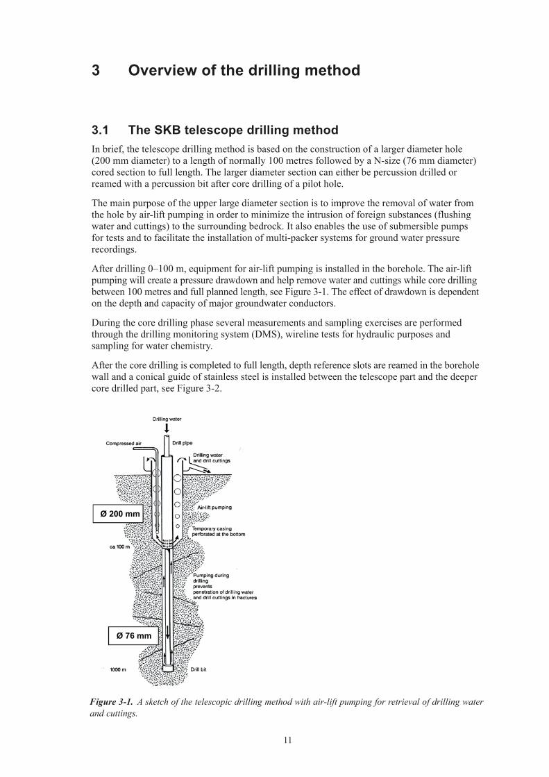
After the core drilling is completed to full length, depth reference slots are reamed in the borehole wall and a conical guide of stainless steel is installed between the telescope part and the deeper core drilled part, see Figure 3-2.
Figure 3-1. A sketch of the telescopic drilling method with air-lift pumping for retrieval of drilling water and cuttings.
Ø 76 mm
Ø 200 mm
12
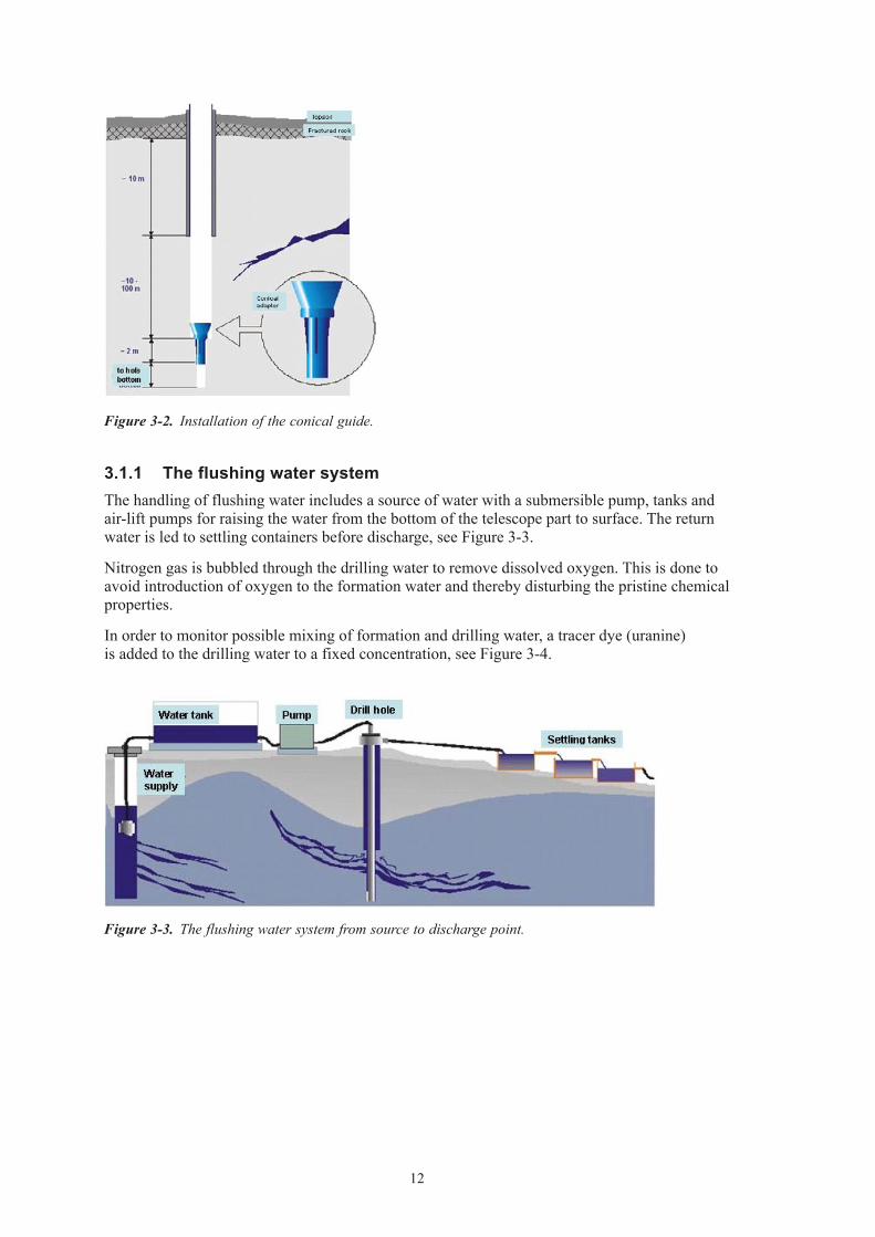
3.1.1 The flushing water systemThe handling of flushing water includes a source of water with a submersible pump, tanks and air-lift pumps for raising the water from the bottom of the telescope part to surface. The return water is led to settling containers before discharge, see Figure 3-3.
Nitrogen gas is bubbled through the drilling water to remove dissolved oxygen. This is done to avoid introduction of oxygen to the formation water and thereby disturbing the pristine chemical properties.
In order to monitor possible mixing of formation and drilling water, a tracer dye (uranine) is added to the drilling water to a fixed concentration, see Figure 3-4.
Figure 3-2. Installation of the conical guide.
Figure 3-3. The flushing water system from source to discharge point.

13
3.2 Measurements and sampling during drilling3.2.1 Percussion drillingDrill cuttings are collected for every metre during the percussion drilling. A preliminary geological logging of the cuttings is done on site. During the preliminary logging notes are made on the dominating lithology, size and shape of the cutting or any other noticeable geological feature. The magnetic susceptibility of the cuttings samples are measured with hand held equipment. Small cups of return water are taken systematically of the return water. The water colour and intensity are noted as indications on degree of rock oxidation and clay content. The return water flow (i.e. the amount of water driven up by compressed air) is measured when noticeable changes in flow occur. The drill penetration rate during percussion drilling is either logged automatically (most common) or manually.
3.2.2 Core drillingThe sampling and measurements during the core drilling phase of KLX17A consisted of:
• Wirelinemeasurements.
• Air-liftpumpingandrecoverytests.
• Watersamplingatthesurface.
• Thedrillingmonitoringsystem.
Wireline measurements and water sampling
The measurements and the sampling are made in the borehole with a wireline based equipment. Pumping tests are evaluated according to Moye /3/ and are normally performed for every 100 metres of drilled length. Sampling of water for chemical analysis is done in conjunction with the pumping tests where feasible. The wireline tests are done in accordance with SKB Method Description MB 321.002, SKB internal document.
NB Measurement of absolute pressure were not done in KLX17A following an internal decision, (Id 1044856, SKB internal document).
PumpFlushing waterto borehole
~ 100 m
Percussionborehole
Nitrogen stationTracer dye
Q-gaugeTank
Downhole pump
Figure 3-4. Schematic drawing of the preparation of flushing water. Uranine is added to the water as a tracer dye and nitrogen is bubbled through the water to remove dissolved oxygen.

14
Air-lift pumping with evaluation of drawdown
Air-lift pumping with evaluation of drawdown is done with 300 metres intervals, nominally at 400 and full drilled length. The actual levels are adapted to when changes of drill bit, or some other reason to raise the drill stem, occur. The test is normally based on the drawdown phase.
• Thetestcycleisstartedwithair-liftpumpinginthetelescopicsection.
• Drillingorotherrelatedactivitiessuchasrinsingofdrillcuttingscanoccurpriortoliftingthe stem. This means that an inflow of water through the drill stem can occur during the initial stages of the test cycle.
• Afterthestemhasbeenremovedtheair-liftpumpingcontinuesbetween30minutesandtwohours to achieve stable conditions.
• Theair-liftpumpingisstopped.
• Therecoveryofthewatertableinthetelescopicsectionismonitored.
Water sampling at the surface
Water samples of flushing and return water, i.e. the water entering and returning from the bore-hole at the surface, are taken at 10 to 20 metre intervals of drilled length for analysis of drilling water content (percentage of water with uranine tracer content) and electrical conductivity.
Drilling monitoring system (DMS)
Drilling is monitored on-line by continuous registration of drill rig and flushing water parameters in accordance with the Method Description for registration and sampling of flushing water parameters during drilling (SKB MD 640.001) and the Method Description for quality assurance of DMS-data (SKB MD 640.008). The Method Descriptions are SKB internal documents. The data is compiled into a database called Drilling Monitoring System (DMS).

15
4 Contractors and equipment
4.1 ContractorsThe main contractor for drilling was Drillcon Core AB, with subcontractor for core drilling Suomen Malmi OY (SMOY) and subcontractor for percussion drilling Sven Andersson AB.
An overview of the organisation for the drilling activity is given in Table 4-1.
Table 4‑1. Drill activity organisation.
Senior ScientistsHydrogeology Mansueto Morosini Hydrochemistry Isabel Hedqvist Geology Peter HultgrenGeophysics Leif Stenberg
Nils HåkanssonRobert SödermanPär VibergAnders HjelmChristian Mutschlechner
Site ManagerPeter Wikberg
Investigation LeaderKarl-Erik Almén
Activity LeaderLars-Eric Samuelsson
PlanningMalin Malmdal
Database operatorsMaria Eriksson
Anne-Marie Lindekrantz
Drilling Coordinators
Measurement systemsLars Andersson
Geology CoordinatorThomas Kisiel
Project Manager Drillcon
Mikael Berglund
Drill ManagerVille TeivalaInge Olsson
Percussion DrillingSven Andersson AB
Core DrillingSMOY
SKB organisation
Contractor organisation
16
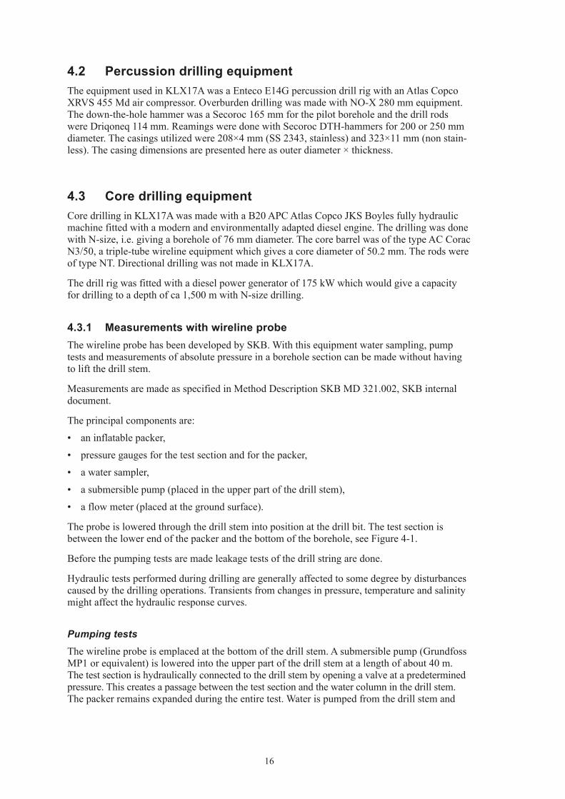
4.2 Percussion drilling equipmentThe equipment used in KLX17A was a Enteco E14G percussion drill rig with an Atlas Copco XRVS 455 Md air compressor. Overburden drilling was made with NO-X 280 mm equipment. The down-the-hole hammer was a Secoroc 165 mm for the pilot borehole and the drill rods were Driqoneq 114 mm. Reamings were done with Secoroc DTH-hammers for 200 or 250 mm diameter. The casings utilized were 208×4 mm (SS 2343, stainless) and 323×11 mm (non stain-less). The casing dimensions are presented here as outer diameter × thickness.
4.3 Core drilling equipmentCore drilling in KLX17A was made with a B20 APC Atlas Copco JKS Boyles fully hydraulic machine fitted with a modern and environmentally adapted diesel engine. The drilling was done with N-size, i.e. giving a borehole of 76 mm diameter. The core barrel was of the type AC Corac N3/50, a triple-tube wireline equipment which gives a core diameter of 50.2 mm. The rods were of type NT. Directional drilling was not made in KLX17A.
The drill rig was fitted with a diesel power generator of 175 kW which would give a capacity for drilling to a depth of ca 1,500 m with N-size drilling.
4.3.1 Measurements with wireline probeThe wireline probe has been developed by SKB. With this equipment water sampling, pump tests and measurements of absolute pressure in a borehole section can be made without having to lift the drill stem.
Measurements are made as specified in Method Description SKB MD 321.002, SKB internal document.
The principal components are:
• aninflatablepacker,
• pressuregaugesforthetestsectionandforthepacker,
• awatersampler,
• asubmersiblepump(placedintheupperpartofthedrillstem),
• aflowmeter(placedatthegroundsurface).
The probe is lowered through the drill stem into position at the drill bit. The test section is between the lower end of the packer and the bottom of the borehole, see Figure 4-1.
Before the pumping tests are made leakage tests of the drill string are done.
Hydraulic tests performed during drilling are generally affected to some degree by disturbances caused by the drilling operations. Transients from changes in pressure, temperature and salinity might affect the hydraulic response curves.
Pumping tests
The wireline probe is emplaced at the bottom of the drill stem. A submersible pump (Grundfoss MP1 or equivalent) is lowered into the upper part of the drill stem at a length of about 40 m. The test section is hydraulically connected to the drill stem by opening a valve at a predetermined pressure. This creates a passage between the test section and the water column in the drill stem. The packer remains expanded during the entire test. Water is pumped from the drill stem and

17
the pressure in the test section and packer are recorded in a data logger. The pumped surface flow rate is recorded in a data logger on the ground surface. The pressure gauge (or pressure transducer) is situated 1.10 m below the lower end of the packer. The test consists of a pressure drawdown phase and a recovery phase. Typically the pumping time is three hours with a recovery phase of the same duration. However, the duration is sometimes adapted to the hydraulic situation of the tested section. The tests are normally carried out in sections of about 100 m length.
Water sampling
The equipment for water sampling is the same as for the pumping tests. The water volume in the section is removed at least three times by pumping water out of the drill stem. The water in the test section is then replaced by formation water and a sample is collected. The wireline probe, with the sampling unit containing a maximum volume of 5 litres, is subsequently brought to the surface.
Pumping tests and water sampling are normally performed as an integrated activity. The aim is to characterize the hydrochemistry as well as the hydrology in the bedrock when the conditions are least affected by hydraulic short circuiting in the borehole.
Absolute pressure measurement
No measurements of absolute pressure were done in KLX17A.
4.3.2 Drilling monitoring systemDuring the core drilling phase continuous monitoring was made of several measurement-while-drilling (MWD) parameters and flushing water parameters. The data is compiled into the DMS database. The procedure for data handling and quality assurance is given in Method Description SKB MD 640.008 (SKB internal document).
Figure 4-1. The wireline probe and its emplacement in the hole.

18
The drill rig (MWD) parameters include:• Rotationalpressure(bar).• Bitforce(kN).• Flushwaterflowin(L/min).• Waterpressureatbit(kPa).• Rotation(rpm).• Penetrationrate(cm/min).
The flushing water parameters include:• Waterlevelinthetelescopepartoftheborehole(kPa).• Oxygenlevelofflushingwater(mg/L).• Flowofflushing(ingoing)andreturn(outgoing)water(L/min).• Electricalconductivityofflushingandreturnwater(mS/m).• Barometricpressure(kPa).
Data from on-line monitoring of flushing water parameters were stored on two different logging units (CR10 and CR23). A separate logging unit was used for the measurement-while-drilling (MWD) dataset. The data from the loggers was downloaded either continuously (CR10 and CR23) or by disk to the DMS database.
4.3.3 Deviation measurementsTwo types of deviation measurements were made:• Measurementstokeeptrackontheboreholeorientationweremadewiththemagnetometer/
accelerometer method Reflex EZ-AQ/EMS (or Easy-Shot) and Flexit, see also Table 5-2 and section 5.3.3.
• Finalmeasurements,alongtheentirelengthoftheboreholeafterthedrillingwascompleted,were made with two methods, Flexit and Maxibor. The Maxibor (Reflex MAXIBOR™ ) is a non-magnetic, optical method. The Flexit instrument (Flexit SmartTool) is based on magnetometer/accelerometer measurements.
4.3.4 Equipment for reaming reference slots In order to establish accurate and similar depth references for the various measurements that will be performed in the borehole, reference slots are reamed in the borehole wall.
The equipment has been developed by SKB and consists of a reaming tool that can be fitted to conventional drilling rods for 56 and 76 mm drilling equipment. The reaming tool is operated hydraulically from the surface, so that the cutters expand when the water pressure is increased.
Figure 4-2. The equipment for reaming of reference slots. To the left, the reaming tool with openings for the cutters is shown. The resulting reference slots are illustrated in the three pictures to the right.

19
5 Execution and results
The original data and results are stored in the SICADA database. Only the datasets in the database will be used for further interpretation and modelling. The data is traceable in SICADA by the Activity Plan number, AP PS 400-06-073.
5.1 Summary of KLX17A drillingA technical summary of the drilling of KLX17A is given in Table 5-1. A graphical presentation of the borehole after completion is given in Figure 5-1. A summary of drilling progress and borehole measurements is given in Table 5-2 and chronological summary is presented in Table 5-3.
Further descriptions of the percussion drilling of the telescopic section 0–65.42 metres and the measurements performed during this phase are given in section 5.2. The core drilling between 65.42–701.08 metres is further described in section 5.3. Results from hydrogeological and hydrogeochemical measurements during core drilling are presented in section 5.4. Drilling progress over time is further reported in section 5.5 “Drilling monitoring results”.
Table 5‑1. KLX17A Technical summary.
General Technical
Name of hole: KLX17A Percussion drill rig Enteco E14GLocation: Laxemar, Oskarshamn Municipality, Sweden
Percussion hole length 65.35 m (diam 196.8 mm)
65.42 m (diam 159.1 mm)Contractor for drilling Drillcon AB
Core drill rig B20 APC Atlas Copco
Subcontractor percussion drilling Sven Andersson AB
Core drill dimension N-size (76 mm)
Cored interval 65.42–701.08 mPercussion drill start date August 7, 2006
Diamond bits used 4
Average bit life 159 metresCompletion date August 15, 2006
Position KLX17A (RT90 RH70) at top of casing:
N 6366848.75 E 1546862.09 Z 27.63 (m.a.s.l.)Subcontractor core drilling Suomen Malmi OY (SMOY)
Azimuth (0–360)/ Dip (0–90)
11.21 / –61.34Core drill start date September 13, 2006
Position KLX17A (RT90 RH70) at 701.08 m length:
N 6367196.14 E 1546962.31 Z –572.47 (m.a.s.l.)Completion date October 23, 2006
Azimuth (0–360)/ Dip (0–90)
14.90 / –56.00

20
6366848.75 (m),1546862.09 (m), 27.63 (m), 2006-08-07 2006-10-23
RT90 2,5 gon V 0:-15 RHB 70
RT90 2,5 gon V 0:-15Northing:Easting:Elevation:
Drilling start date:Drilling stop date:
Drilling reference point
Drilling period
Ver 2007-04-16
Technical dataBorehole KLX17A Drilling reference point
Cement, gap injection
Concrete platform
Ground level
Ø=195 mm
Øo/ =104/100 mmØi
Ø=84 mmØ=77 mm M80x1.5 mm left hand thread
Øo/ =84/80 mmØi
300
mm
2970
mm
4740
mm
1770
mm
A
North
11.21o
-61.34o
Ø = 197.0 mm
Ø = 196.8 mm
Øo/=
323/310 mmØi
Øo/=
323/280 mmØi
Øo/= 208/200 mm
Øi
Ø = 75.8 mm
A
0.15 m
2.60 m2.50 m
Ø = 339 mm
65.42 m
62.02 m
701.08 m
Ø = 159.1 mm
Ø = 86.0 mm
65.35m66.76 m
11.95 m
Ø = 248 mm
Figure 5-1. Technical data from KLX17A.

21
Table 5‑2. Summary of core drilling progress and borehole measurements in KLX17A.
bh metres Drilled length, pumping tests and water sampling
Airlift pumping with evaluation of drawdown and/or recovery
Deviation measurement Miscellaneous
060807–060815 Percussion drilling of the telescopic section 0–65.45 m (pilot) Reaming Ø 196.8 mm 0–65.35 m Stainless casing 0–11.95 m.
060810 Easy-shot at 60 m Azimuth 8.8 Dip –61.1.
100
060816 Collar survey Azimuth 11.2 Dip –61.3.
060916 Easy-shot at 106 m Azimuth 12.3 Dip –61.0.
060916–060917 Pore water sampling campaign ( 55 samples) between drilled lengths 111 and 134 metres.
200
060920 Pumping test 67.00–187.52 m. 7 L/min at approximately 12 m drawdown. Water sample taken.
060920 Easy-shot at 186 m Azimuth 19.7 Dip –60.7.
060923 Maxibor at 237 m 300
060926 Pumping test 187.00–280.98 m. Water flow 1.9 L/min at approximately 17 m drawdown. No water sample.
060928 Easy-shot at 307 m Azimuth 23.2 Dip –59.6.
060924–061019 Pore water sampling (5 samples) with approx. 100 metre spacing between 238 and 634 m drilled length.
400
061002 Pumping test 280.50–393.91 m. Water flow 0 L/min at 18 m drawdown. No water sample.
061001 Easy-shot at 379 m Azimuth 17.8 Dip –59.2.
061004 Pumping test 392.40–430.60 m. Water flow 8 L/min at 8 m drawdown. Water sample taken.
060929–061006 Sampling of suspended material in return water (17 samples in total). Sampling was done at the emission point.
500
061007 Airlift puming 11.95–497.00 m. No drillstem in borehole.
061007 Easy-shot at 494 m Azimuth 15.0 Dip –58.2.
061007 Cleaning of the flushing water system with Freebact
061009 Pumping test 430.00–524.00 m. Water flow 0.1 L/min at approximately 17 m drawdown. No water sample.
600
061015 Easy-shot at 597 m Azimuth 16.6 Dip –56.7.
061016 Pumping test 521.62–632.08 m. Water flow 0.3 L/min at approximately 18 m drawdown. No water sample.
700
061023 Drilling stopped at 701.08 m. Pumping test 629.92–701.08 m. Water flow 0.2 L/min at approximately 18 m drawdown. No water sample.
061025 Airlift pumping 11.95–701.08 m. No drillstem in borehole.
061031 Final Maxibor at 696 m
061028 10:16–061029 09:23 Interference test with drill stem lowered to 420 m. Pressure logger at 419,23 m. Air-lift pumping in telescopic section and in drill stem. Pumped volume ca 35 cu m.
Table 5‑3. Chronological summary of main core drilling events in KLX17A.
22
5.2 Drilling, measurements and results in the telescopic section 0–65.42 m
Drilling, reaming and grouting (gap injection) were made from August 7 to 15, 2006.
5.2.1 PreparationsA cement pad for emplacement of drill rig, fuel container and compressor was built. A suitable area was cleared and levelled for establishing of a drill site. Cleaning of all DTH (down-the-hole) equipment was done with a high-capacity steam cleaner.
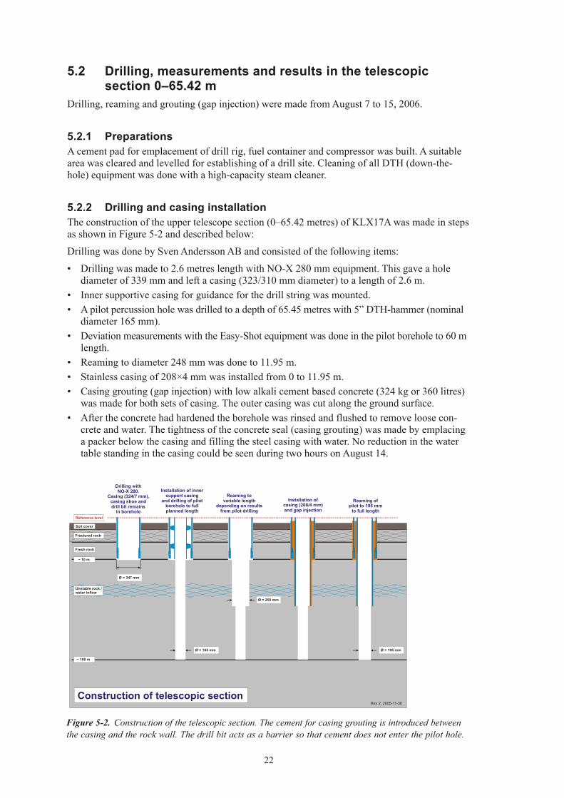
5.2.2 Drilling and casing installationThe construction of the upper telescope section (0–65.42 metres) of KLX17A was made in steps as shown in Figure 5-2 and described below:
Drilling was done by Sven Andersson AB and consisted of the following items:
• Drillingwasmadeto2.6metreslengthwithNO-X280mmequipment.Thisgaveaholediameter of 339 mm and left a casing (323/310 mm diameter) to a length of 2.6 m.
• Innersupportivecasingforguidanceforthedrillstringwasmounted.• Apilotpercussionholewasdrilledtoadepthof65.45metreswith5”DTH-hammer(nominal
diameter 165 mm).• DeviationmeasurementswiththeEasy-Shotequipmentwasdoneinthepilotboreholeto60m
length. • Reamingtodiameter248mmwasdoneto11.95m.• Stainlesscasingof208×4mmwasinstalledfrom0to11.95m.• Casinggrouting(gapinjection)withlowalkalicementbasedconcrete(324kgor360litres)
was made for both sets of casing. The outer casing was cut along the ground surface.• Aftertheconcretehadhardenedtheboreholewasrinsedandflushedtoremoveloosecon-
crete and water. The tightness of the concrete seal (casing grouting) was made by emplacing a packer below the casing and filling the steel casing with water. No reduction in the water table standing in the casing could be seen during two hours on August 14.
Figure 5-2. Construction of the telescopic section. The cement for casing grouting is introduced between the casing and the rock wall. The drill bit acts as a barrier so that cement does not enter the pilot hole.
~ 100 m
~ 10 m
Construction of telescopic section
Soil cover
Fractured rock
Reference level
Unstable rock /water inflow
Ø = 347 mm
Installation ofcasing (208/4 mm)and gap injection
Reaming tovariable length
depending on resultsfrom pilot drilling
Drilling withNO-X 280.
Casing (324/7 mm),casing shoe anddrill bit remains
in borehole
Installation of innersupport casing
and drilling of pilot borehole to fullplanned length
Reaming ofpilot to 195 mm
to full length
Fresh rock
Ø = 250 mm
Ø = 165 mm Ø = 195 mm
Rev 2, 2005-11-30

23
5.2.3 Measurements and sampling during drilling of the telescopic sectionSampling and measurements done during drilling of the telescopic section included:
• Thepercussiondrillingprogresswasmonitoredbyacontractedgeologist.Drillcuttingssamples were collected every metre and a preliminary geological logging including measure-ment of magnetic susceptibility was made.
• Penetrationrate(expressedassecondsper20cm)wasrecordedautomaticallyandobservationof changes in water flow was noted.
The preliminary geological results with penetration rate and magnetic susceptibility as measured on the cuttings are presented in Figure 5-3.
Figure 5-3. Preliminary geological results based on logging of drill cuttings and penetration rate from percussion drilling of KLX17A.

24
The depth to bedrock from top of casing (TOC) was 1.5 m. The depth of overburden (ground surface to rock) was 0.15 metres i.e. the drilling reference level (TOC) was located 15 cm above the concrete slab. No natural soils were encountered, the overburden consisted of concrete and gravel fill.
The results from the preliminary geological logging, measurements of magnetic susceptibility in the drill cuttings and water flow during drilling are given in Figure 5-3.
No water samples were collected in the telescopic section in KLX17A as no inflow of water could be noted during the drilling of the telescopic section.
5.2.4 Hydrogeological measurements and results during percussion drillingNo pumping test was performed in the percussion drilled part of KLX17A.
5.3 Core drilling KLX17A 65.42–701.08 mCore drilling in KLX17A was conducted between September 13 and October 23, 2006.
The main work in KLX17A after drilling the telescopic section consisted of the following steps:
• preparationsforcoredrilling,
• flushingandreturnwaterhandling,
• coredrillinganddeviationmeasurements,
• boreholecompletionincludingriskassessmentoftheboreholewallstability.
Measurements and results from wireline tests and drilling monitoring are given in sections 5.4 and 5.5.
5.3.1 PreparationsThe preparations for core drilling started on September 7, 2006 and consisted of mounting the drill rig, installation of air-lift pumping equipment and supportive casing for alignment of the core drill rods, see Figure 5-4.
The installation of supportive casing was done in steps:
• Anoutercasingwithadiameterof98/89mm,fittedwithfinstoalignwiththediameterofthe percussion drilled borehole was installed to 65.26 m.
• Equipmentforair-liftpumpingwasinstalledandadischargeheaderwasfittedtocollectthereturn water.
• Drillingwasmadebetween65.42and65.85mwithT-86equipment.Aninnersupportivecasing with diameter 84/77 mm was installed to the borehole bottom.
The supportive casings have a perforated section below 60 metres length so that water from the borehole can be lead to the air-lift pumping system outside the supportive casings. A pressure meter for monitoring of the water level was emplaced at a length of 60 metres.

25
5.3.2 Flushing and return water handlingThe flushing water source was percussion borehole HLX14, see also sections 5.4.2 and 5.5. The location of the water source, borehole HLX14 is shown in Figure 1-1.
Treatment of the flushing water before introduction into the boreholes consisted of stripping (removal) of oxygen with nitrogen gas and addition of the fluorescent tracer uranine. The water is also treated with ultraviolet light in order to reduce the microbial content. The flushing and return water handling and the emplacement of related monitoring equipment in KLX17A is shown in Figure 5-5.
The targeted content for uranine in the flushing water was 0.20 mg/L and the actual average uranine content was 0.218 mg/L, see also Figure 5-9 and section 5.4.2.
The return water from drilling was led to a series of sedimentation containers in order to collect cuttings before infiltration to the ground, see also section 5.8.
5.3.3 Drilling and deviation measurements KLX17ACore drilling with T-86 equipment giving an 86 mm diameter hole was done from 65.42 to 65.85 m in KLX17A. The part from 65.85 to 66.76 m was first drilled with N-size and subse-quently reamed to T-86 as part of the borehole completion, see section 5.3.4.
Core drilling with N-size (76 mm) triple-tube, wireline equipment was conducted from 65.85 m to the final length of 701.08 m in KLX17A.
The core diameters and intervals for drilling dimensions are given in Table 5-4. Directional drilling, i.e. intentional change of direction or dip of the borehole was not made in KLX17A.
Figure 5-4. In the telescopic part of the drill hole a temporary installation is made with casing tubes for support and alignment and equipment for air-lift pumping. In the uppermost part the return water discharge header is mounted. The water discharge is led to the settling containers.

26
Measurements of borehole deviation are made for two purposes:
• Monitoringofdrillingprogress.
• Measurementsatfulldrilledlengthforfinalcalculationofboreholedeviation.
The core drilling progress was followed by deviation measurements six times with the EZ-shot method along the core drilled section of the borehole and once with the Maxibor method at 237 metres drilled length. The results from these measurements are not stored in the Sicada database but are given in a summary fashion in Table 5-2.
Measurements were done with the Maxibor method for the final evaluation of the borehole deviation in KLX17A. The Maxibor measurement was done as part of the drilling activity. Measurements with the Maxibor instrument were performed both up and down the hole between 0 and 696 metres.
Flow meter
UV- lamp
Uranine
tracer
Water tank
Oxygen meter
El cond meter Flushing water
Flushing water well HLX14
HLX14
Borehole KLX17A
Degasser
El cond meter Return water
Return water
Flow meter
Sedimentation
Infiltration
Nitrogen gas
Flow
meter
El cond meter
Infiltration
Pump MP1 for pumping test.
Table 5‑4. Core diameters, borehole diameters and drilling dimensions during core drilling in KLX17A.
Core diameter (mm)
Borehole diameter (mm)
Interval (m drilled length)
Drilling dimension Comment
72.0 86 65.42–65.85 T-8650.2 86 65.85–66.76 N and T-86 Reamed to 86 mm diameter50.2 76 66.76–701.08 N
Figure 5-5. The flushing and return water handling and the emplacement of related monitoring equipment in KLX17A.

27
The final deviation file in KLX17A is calculated based on the measurements given in Table 5-5 together with the surveyed bearing and inclination of the top-of-casing. The calculations are made according to routines specified in the SICADA database and general expert judgement. Further comment on the method for calculation of final borehole deviation is given in /4/.
Horizontal and vertical plots of the results of the calculated deviation covering the entire length of borehole KLX17A are given in Appendix 4.
Two sections with core losses were noted in KLX17A during the Boremap (geological) mapping: 108.70–109.50 and 111.23–111.44 m, see also Figure 5-10 in section 5.4.2. The core losses were labelled as “crushed zone”.
A total of four drill bits were used for KLX17A, see Figure 5-6.
Further results from drill monitoring i.e. drill penetration rate and various measurements will be presented in section 5.5 “Drilling monitoring results” and in Appendix 1.
Table 5‑5. Measurements used for borehole deviation calculation in KLX17A.
Deviation meas‑urement method
Used for calcula‑tion of bearing/ inclination
Interval From (m)
Interval To (m)
Measuring direction
Date Sicada database activity ID
Maxibor BEARING 3 696 down/in 2006-10-31 13134858Maxibor INCLINATION 3 696 down/in 2006-10-31 13134858Maxibor BEARING 3 696 up/out 2006-10-31 13134857Maxibor INCLINATION 3 696 up/out 2006-10-31 13134857
Number of drill bits used in KLX17A
0
100
200
300
400
500
600
700
800
0 1 2 3 4 5
drill
ed le
ngth
(m)
Figure 5-6. Drill bit changes during core drilling in KLX17A.

28
5.3.4 Borehole wall risk assessment, stabilisation and completionBorehole wall risk assessment and stabilisation
A borehole wall assessment was prepared on November 30, 2006, SKB id no 1064639, SKB internal document.
The main drilling events that have influence on the risk assessment are summarized as follows:
• Diamonddrillingcompletedat701.08monOctober23.
• Flushingandbrushingwithhighwaterpressureontheboreholewallwasdonealongintervals as given in Table 5-6. The selection of the intervals to rinse was based on study of the drill core. The flush and brush tool is shown in Figure 5-7.
• Thesteeldummywasloweredwithoutanyproblemsalongtheentirelengthoftheborehole.The probe is designed so that it will run smoothly along the borehole if the curvature does not exceed 0.1 degree/metre.
• Downholeoperationsconsistingofdeviationmeasurements,millingofreferencegroovesand flushing of the borehole with nitrogen gas were made without stability problems.
• BIPSloggingforfinalriskassessmentwasdonetoalongthefulldrilledlength.
The overall assessment was that the probability for rock fallout was low to medium in the borehole.
Table 5‑6. Borehole sections that were mechanically rinsed by water flushing and rotating steel brush.
From (bh length m) To (bh length m)
70 73100 118200 201202.5 203.5207 208214.5 215.5217 218221 222249.5 250.5290 291316 317393.5 394.5423.5 424477.5 478.50

29
Borehole completion
Reaming of depth reference slots was done at the drilled lengths shown in Table 5-7. The depth reference slots are used for depth calibration of down-hole equipment for subsequent investiga-tions in the hole. The presence of the depth reference slots have been confirmed by caliper log measurements.
The air lift pumping equipment and the inner supportive casing in the telescopic section were removed.
The borehole was reamed from 65.42 to 66.76 with T-86 equipment. A steel conical guide was installed in KLX17A between 62.02 m and 66.76 m. The conical guide tapers from an inner diameter of 195 mm to 77 mm.
The length of the holes was rinsed by flushing (lifting) with nitrogen gas at times given in Table 5-8.
The boreholes were secured by mounting of lockable steel caps fastened to the concrete pad. All equipment was removed, the site cleaned and inspected by representatives from SKB and the contractor to ensure that the site had been satisfactorily restored.
Table 5‑7. Depth reference slots (m) in KLX17A.
75.00 400.00100.00 450.00150.00 500.00200.00 550.00250.00 600.00300.00 650.00350.00 680.00
Figure 5-7. The water flushing and rotating steel brush tool. The tool is lowered into the drill stem and can be seen in place just below the drill bit. During operating the drill string is moved up and down to remove loose rock fragments from the borehole wall.

30
Table 5‑8. Nitrogen gas lifting in KLX17A. (time is in Swedish Normal Time i.e. GMT+1).
Date Time Interval (m) Volume removed (m3)
061105 08.06–08.24 11.95–701.08 0.4061105 08.33–08.50 11.95–701.08 0.4061105 09.09–09.29 11.95–701.08 0.3061105 10.01–10.18 11.95–701.08 0.4061105 10.45–11.03 11.95–701.08 0.4
5.4 Hydrogeological and hydrochemical measurements and results 65.42–701.08 m.
The performed measurements, as already outlined in Tables 5-2 and 5-3, can be summarized as follows
Measurements and sampling with wireline equipment:
• Sevencompletelysuccessfultestswereconductedoutofelevenattemptsatvariousintervals,see section 5.4.1.
• Twowatersamplesweretaken,seesection5.4.2.
Two air-lift pumping tests with evaluation of drawdown and/or recovery phase were made, for results see section 5.4.3.
Hydraulic responses in near-by boreholes from drilling in KLX17A are commented in section 5.4.4.
5.4.1 Hydrogeological results from wireline measurementsResults from the wire line tests in KLX17A are presented in Table 5-9 and Figure 5-8.
The pumping tests were evaluated with steady-state assumption in accordance with Moye /3/. The flow rate at the end of the drawdown phase was used for calculating the transmissivity (TM) and the specific capacity (Q/s), where Q is the flow rate and s is the drawdown.
A total of eleven tests were performed in KLX17A. Four failed and seven achieved sufficiently stable conditions for calculating pseudo steady-state transmissivity and hydraulic conductivity. The reason behind the failed tests is mainly leakage between the casing and the tested section caused by a malfunctioning wire line probe or leakage between the pipe string and the borehole.
In order to diminish the potential leakage, the check valve was sealed prior to tests in KLX17A. This could explain the instantaneous pressure increase at pump stop, as can be seen on most pressure graphs.
The plots from the pumping tests are given in Appendix 5.
The start and stop times (local time) for the interval used for evaluation of the pumping tests are given in Table 5-10.

31
Table 5‑9. Pumping tests with wireline probe in KLX17A.
Tested section [m] Q/s [m2/s] TM [m2/s] Comments
67.00–187.52 1.4 ∙10–5 1.6 ∙10–5 Pseudo steady state conditions prevail during the pumping, with a stable flow rate and a almost constant section pressure. The electric conductivity decreased during the whole flowing phase.
187.00–280.98 1.8 ∙10–6 2.3 ∙10–6 Bad test: Two or three pumping breaks during the first hour of the flowing phase and 30 minutes before pump stop an additional pump failure occurred. The section pressure increased during the pumping.
280.50–393.91 1.0 ∙10–7 1.3 ∙10–7 Bad test: The pumping was interrupted after 26 minutes. The flow was too low for the pump. Two pumping breaks occurred. Flow and pressure are far from stable. The flow rates are most uncertain, Qp is set to = 0.1 L/min (assumed lower measurement limit). The calculated values of K and T are also uncertain.
392.40–430.60 2.2 ∙10–5 2.5 ∙10–5 A small leakage (0.033 L/min) from the pipe string was observed before the test.
The electric conductivity starts to increase c. 2 hours after pump start. The section pressure and the flow rate were at a constant level during the second half of the test. A water-bearing fracture at depth 427 m was observed during drilling.
430.00–524.00 9.5 ∙10–8 1.2 ∙10–7 Pseudo steady state conditions prevail during the pumping, with a small stable flow rate and an almost constant section pressure. The pressure does not recover after pump stop.
521.62–623.08 1.8 ∙10–7 2.3 ∙10–7 During the pumping both the section pressure and the flow rate were stable at a constant level. But after the pump stop the section pressure declined!
629.92–701.08 8.5 ∙10–8 1.1 ∙10–7 Pseudo steady state conditions prevail during the pumping, with a small stable flow rate and a almost constant section pressure.
Table 5‑10. Evaluated test periods.
Tested section Start (YYYY‑MM‑DD HH:MM) Stop (YYYY‑MM‑DD HH:MM)
67.00–187.52 2006-09-20 16:37 2006-09-21 03:07187.00–280.98 2006-09-26 18:05 2006-09-26 20:37280.50–393.91 2006-10-02 17:37 2006-10-02 18:09392.40–430.60 2006-10-04 18:21 2006-10-05 03:06430.00–524.00 2006-10-09 16:52 2006-10-09 20:04521.62–623.08 2006-10-16 17:36 2006-10-16 20:34629.92–701.08 2006-10-23 17:18 2006-10-23 20:41

32
5.4.2 HydrochemistryTwo water samples were collected in connection with core drilling in KLX17A. Time and length for the samples are given in Table 5-11.
Sampling and analysis were performed according to the SKB classes specified in Table 5-11. The samples were collected at the drill site as soon as possible after the sampling occasion and prepared and conserved at the Äspö laboratory. The samples were stored in refrigerator until the drilling of the borehole was completed.
The drill water content in both samples, 11355 and 11376, were considered low enough to analyse the samples for isotopes. The drilling water content is a measure of the amount of uranine tracer in the return water. A low percentage of drilling water implies that the amount of pristine formation water is high in the sample i.e. low amount of the uranine-spiked flushing water, see Table 5-12.
Archive bottles have been collected for the samples above and are stored in a freezer at the Äspö laboratory.
Selected analytical results from KLX17A are given in Table 5-12. A complete record of analytical results is given in Appendix 2.
Table 5‑11. Sample dates and length during core drilling in KLX17A.
Sample number Borehole Date Test section, length (m) SKB chemistry class
11355 KLX17A 2006-09-17 67.00–187.52 3 (and all option isotopes)11376 KLX17A 2006-10-05 392.40–430.60 3 (and all option isotopes)
KLX17A
0
100
200
300
400
500
600
700
1.00E-08 1.00E-07 1.00E-06 1.00E-05 1.00E-04 1.00E-03
Leng
th [m
]Transmissivity, TM [m2/s]
Figure 5-8. Transmissivity from wireline pumping tests in KLX17A versus borehole length.
33
Table 5‑12 Analytical results from water chemistry sampling.
Borehole Sample no
Date From m
To m
Drill water %
pH Conductivity mS/m
Cl mg/l
KLX17A 11355 2006-09-17 67.00 187.52 20.90 8.64 57.5 43.7KLX17A 11376 2006-10-05 392.40 430.60 9.32 7.30 282.0 809.0
The percussion drilled borehole HLX14 was used as water source during the drilling of KLX17A. No water samples were collected from HLX14 in connection with the drilling of KLX17A. However, water samples have been collected from HLX14 at earlier occasions and results from those analyses are reported in /5/.
Monitoring of uranine tracer content
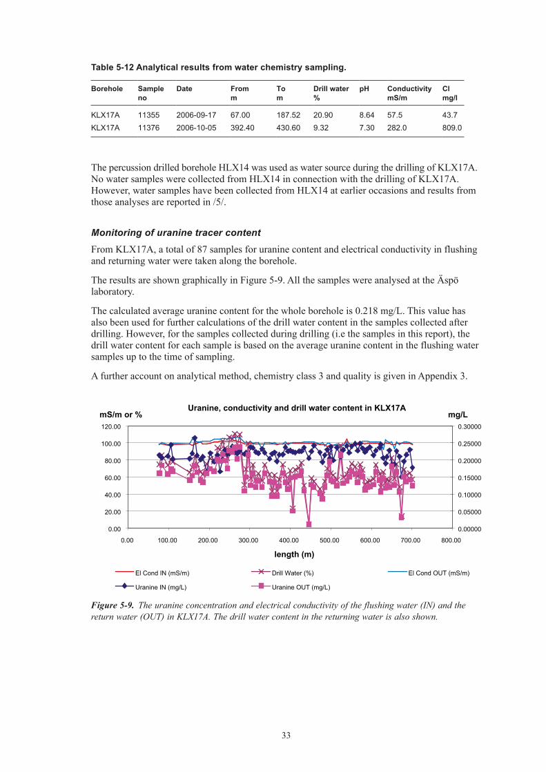
From KLX17A, a total of 87 samples for uranine content and electrical conductivity in flushing and returning water were taken along the borehole.
The results are shown graphically in Figure 5-9. All the samples were analysed at the Äspö laboratory.
The calculated average uranine content for the whole borehole is 0.218 mg/L. This value has also been used for further calculations of the drill water content in the samples collected after drilling. However, for the samples collected during drilling (i.e the samples in this report), the drill water content for each sample is based on the average uranine content in the flushing water samples up to the time of sampling.
A further account on analytical method, chemistry class 3 and quality is given in Appendix 3.
Uranine, conductivity and drill water content in KLX17A
0.00
20.00
40.00
60.00
80.00
100.00
120.00
0.00 100.00 200.00 300.00 400.00 500.00 600.00 700.00 800.00
length (m)
mS/m or %
0.00000
0.05000
0.10000
0.15000
0.20000
0.25000
0.30000
El Cond IN (mS/m) Drill Water (%) El Cond OUT (mS/m)
Uranine IN (mg/L) Uranine OUT (mg/L)
mg/L
Figure 5-9. The uranine concentration and electrical conductivity of the flushing water (IN) and the return water (OUT) in KLX17A. The drill water content in the returning water is also shown.
34
Sampling of microbes
A total of 16 samples were taken in order to determine the microorganism content within the flushing water system. The samples were all collected after cleaning the flushing water system. Half of the samples were collected on September 21, 2006 and the rest were collected on October 11. The samples were taken from four different locations within the flushing water system. A significant reduction of the bacterial content could be noted in the second round of samples i.e. after the flushing water preparation system had been cleaned on October 7. The results are reported in full in Pedersen, 2006 /6/.
Pore matrix sampling
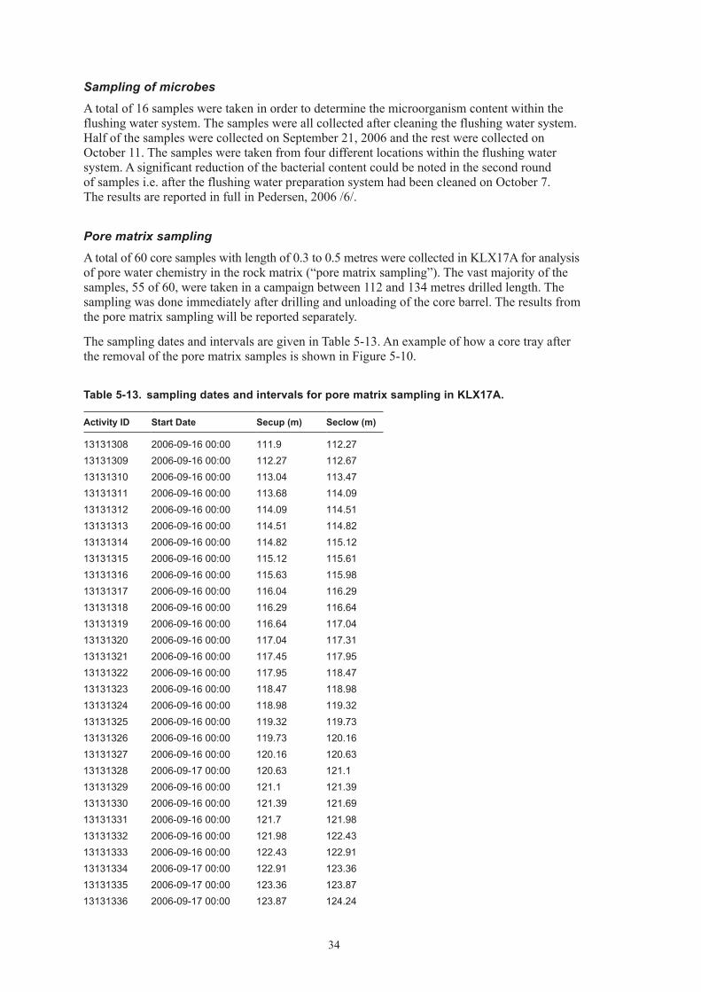
A total of 60 core samples with length of 0.3 to 0.5 metres were collected in KLX17A for analysis of pore water chemistry in the rock matrix (“pore matrix sampling”). The vast majority of the samples, 55 of 60, were taken in a campaign between 112 and 134 metres drilled length. The sampling was done immediately after drilling and unloading of the core barrel. The results from the pore matrix sampling will be reported separately.
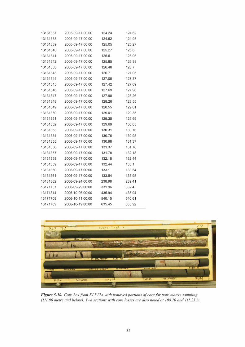
The sampling dates and intervals are given in Table 5-13. An example of how a core tray after the removal of the pore matrix samples is shown in Figure 5-10.
Table 5‑13. sampling dates and intervals for pore matrix sampling in KLX17A.
Activity ID Start Date Secup (m) Seclow (m)
13131308 2006-09-16 00:00 111.9 112.2713131309 2006-09-16 00:00 112.27 112.6713131310 2006-09-16 00:00 113.04 113.4713131311 2006-09-16 00:00 113.68 114.0913131312 2006-09-16 00:00 114.09 114.5113131313 2006-09-16 00:00 114.51 114.8213131314 2006-09-16 00:00 114.82 115.1213131315 2006-09-16 00:00 115.12 115.6113131316 2006-09-16 00:00 115.63 115.9813131317 2006-09-16 00:00 116.04 116.2913131318 2006-09-16 00:00 116.29 116.6413131319 2006-09-16 00:00 116.64 117.0413131320 2006-09-16 00:00 117.04 117.3113131321 2006-09-16 00:00 117.45 117.9513131322 2006-09-16 00:00 117.95 118.4713131323 2006-09-16 00:00 118.47 118.9813131324 2006-09-16 00:00 118.98 119.3213131325 2006-09-16 00:00 119.32 119.7313131326 2006-09-16 00:00 119.73 120.1613131327 2006-09-16 00:00 120.16 120.6313131328 2006-09-17 00:00 120.63 121.113131329 2006-09-16 00:00 121.1 121.3913131330 2006-09-16 00:00 121.39 121.6913131331 2006-09-16 00:00 121.7 121.9813131332 2006-09-16 00:00 121.98 122.4313131333 2006-09-16 00:00 122.43 122.9113131334 2006-09-17 00:00 122.91 123.3613131335 2006-09-17 00:00 123.36 123.8713131336 2006-09-17 00:00 123.87 124.24
35
13131337 2006-09-17 00:00 124.24 124.6213131338 2006-09-17 00:00 124.62 124.9813131339 2006-09-17 00:00 125.05 125.2713131340 2006-09-17 00:00 125.27 125.613131341 2006-09-17 00:00 125.6 125.9513131342 2006-09-17 00:00 125.95 126.3813131363 2006-09-17 00:00 126.48 126.713131343 2006-09-17 00:00 126.7 127.0513131344 2006-09-17 00:00 127.05 127.3713131345 2006-09-17 00:00 127.42 127.6913131346 2006-09-17 00:00 127.69 127.9813131347 2006-09-17 00:00 127.98 128.2613131348 2006-09-17 00:00 128.26 128.5513131349 2006-09-17 00:00 128.55 129.0113131350 2006-09-17 00:00 129.01 129.3513131351 2006-09-17 00:00 129.35 129.6913131352 2006-09-17 00:00 129.69 130.0513131353 2006-09-17 00:00 130.31 130.7613131354 2006-09-17 00:00 130.76 130.9813131355 2006-09-17 00:00 130.98 131.3713131356 2006-09-17 00:00 131.37 131.7813131357 2006-09-17 00:00 131.78 132.1813131358 2006-09-17 00:00 132.18 132.4413131359 2006-09-17 00:00 132.44 133.113131360 2006-09-17 00:00 133.1 133.5413131361 2006-09-17 00:00 133.54 133.9813131362 2006-09-24 00:00 238.98 239.4113171707 2006-09-29 00:00 331.96 332.413171814 2006-10-06 00:00 435.94 435.9413171708 2006-10-11 00:00 540.15 540.6113171709 2006-10-19 00:00 635.45 635.92
Figure 5-10. Core box from KLX17A with removed portions of core for pore matrix sampling (111.90 metre and below). Two sections with core losses are also noted at 108.70 and 111.23 m.
36
5.4.3 Results from air‑lift pumping with evaluation of drawdown and/or recovery
One airlift pumping test was conducted during drilling, and one additional test was conducted after the borehole was drilled to full depth. The execution of the tests varies in detail as drilling or other related activities such as cleaning and flushing of drill cuttings may occur prior to lifting the stem.
The steady state transmissivity, TM, as well as the specific capacity, Q / s, was calculated according to Moye /3/. The results are shown in Table 5-14 and stored in the SICADA database as “recovery tests” (code HY050). The tested section is here defined as the section between the lower end of the grouted casing and the borehole bottom.
The plots from the drawdown and recovery tests are given in Figures 5-11 and 5-12.
5.4.4 Hydraulic responses in near‑by boreholes.Hydraulic responses from drilling activities in a borehole are created by the drawdown from air-lift pumping during core drilling and from flushing or rinsing the borehole with nitrogen gas (i.e. lifting the water with nitrogen gas). Percussion drilling of the telescopic section also constitutes an air-lift pumping from a hydrogeological point of view. All times in plots in this section (section 5.4.4) are given in Swedish Normal Time (GMT+1).
Summary conclusions are listed below. The locations of the observation boreholes, flushing water supply well and KLX17A are shown in Figure 5-23.
• NocorrelationbetweengroundwaterlevelsintheobservationboreholesKLX04,KLX06,HLX34, HLX35, HLX36, HLX37, HLX38 or HLX41 and the drilling activities in borehole KLX17A could be found.
• Hydraulicresponsesfromaninterferencetest(i.e.pumpinginKLX17A)onOctober28–29could be seen in HLX39, HLX40 and the upper most section in KLX13A.
• AhydraulicresponsefromnitrogenliftinginKLX17Acouldbeseenintheuppermostsection in KLX13A.
• Thereisahydraulicconnectionbetweentheflushingwaterwell(HLX14)and– the lower section in borehole HLX35, – the upper sections in KLX04.
No data was available for KLX08 during the drilling in KLX17A.
Table 5‑14. Results from airlift pumping in KLX17A.
Tested section [m] Flow rate [L/min]
Drawdown [m]
Q/s [m2/s]
TM [m2/s]
Comments
11.95–497.00 28 14 3.3∙10–5 5.210–5 Disturbed conditions prevailed prior to the test. The stabilized head from the recovery was used to estimate the drawdown when evaluating the test.
11.95–701.08 22 18.1 2.0∙10–5 3.3∙10–5 Cleaning and some flushing were carried out in the borehole during the air-lift pumping.

37
Evaluated period
Water flow (out) L/min Water column (m) Water flow (in) L/min
Figure 5-11. Airlift pumping in KLX17A 11.95–497.00 m. The green line represents the height of the water column in the borehole, the flow out of the borehole is shown as the blue dotted line and the inflow rate as the red line. Times are given in local time (GMT+2).
Figure 5-12. Airlift pumping in KLX17A 11.95–701.08 m. The green line represents the height of the water column in the borehole, the flow out of the borehole is shown as the blue dotted line and the inflow rate as the red line. Times are given in local time i.e. with daylight saving time (GMT+2).
Water column (m) Water flow (out) L/min Water flow (in) L/min
Evaluated period

38
Hydraulic responses in near-by boreholes from percussion of the telescopic section in KLX17A
No hydraulic responses from percussion drilling in KLX17A could be seen in the observation boreholes KLX04, KLX06, HLX34, HLX35, HLX36, HLX37, HLX39, HLX40 or HLX41. No data was available from KLX08, KLX11A, KLX13A, KLX20A or HLX38.
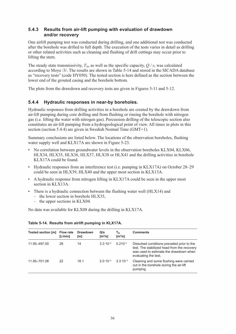
A plot showing the water table in the water supply well HX14 and observation boreholes HLX34, HLX35, HLX36 and HLX37 during percussion drilling of the telescopic section in KLX17A is given in Figure 5-13. No response from percussion drilling in KLX17A could be seen in the observation boreholes HLX34, HLX35, HLX36 and HLX37. The water table in HLX37 was however heavily affected by the pumping in HLX28 and air-lifting in KLX19A /7/.
A plot giving the water table in the supply well HLX14 and observation boreholes HLX39, HLX40 and HLX41 during percussion drilling of the telescopic section in KLX17A is shown in Figure 5-14. No response from percussion drilling in KLX17A could be seen in the three observation boreholes, which is quite surprising given the closeness of the three percussion boreholes HLX39, HLX40 and HLX41 to borehole KLX17A. It should be noted, however, that there was no measurable amounts of water encountered during drilling of the telescopic section of KLX17A.
Hydraulic responses in near-by boreholes from air-lift pumping during core drilling in KLX17A and the interference test at the end of the core drilling phase
A clear correlation is visible in Figures 5-15 between the pumping in the water supply well HLX14 and the water table in the lower section of HLX35. There is also a clear recovery in the water levels in the upper sections of KLX04 when pumping was stopped in the water supply well HLX14, see Figure 5-16.
No response from strict drilling activities in KLX17A can be seen in any of the observation boreholes (HLX34, HLX35, HLX36, HLX37, HLX38, HLX39, HLX40, HLX41, KLX04, KLX06, KLX11A, KLX13A),see Figures 5-15, 5-16, 5-17, 5-18 and 5-19. No plot is given for borehole KLX20A, but no response was encountered in this borehole from core drilling or related pumping activities in KLX17A.
No data was available from KLX08 during the core drilling phase in KLX17A.
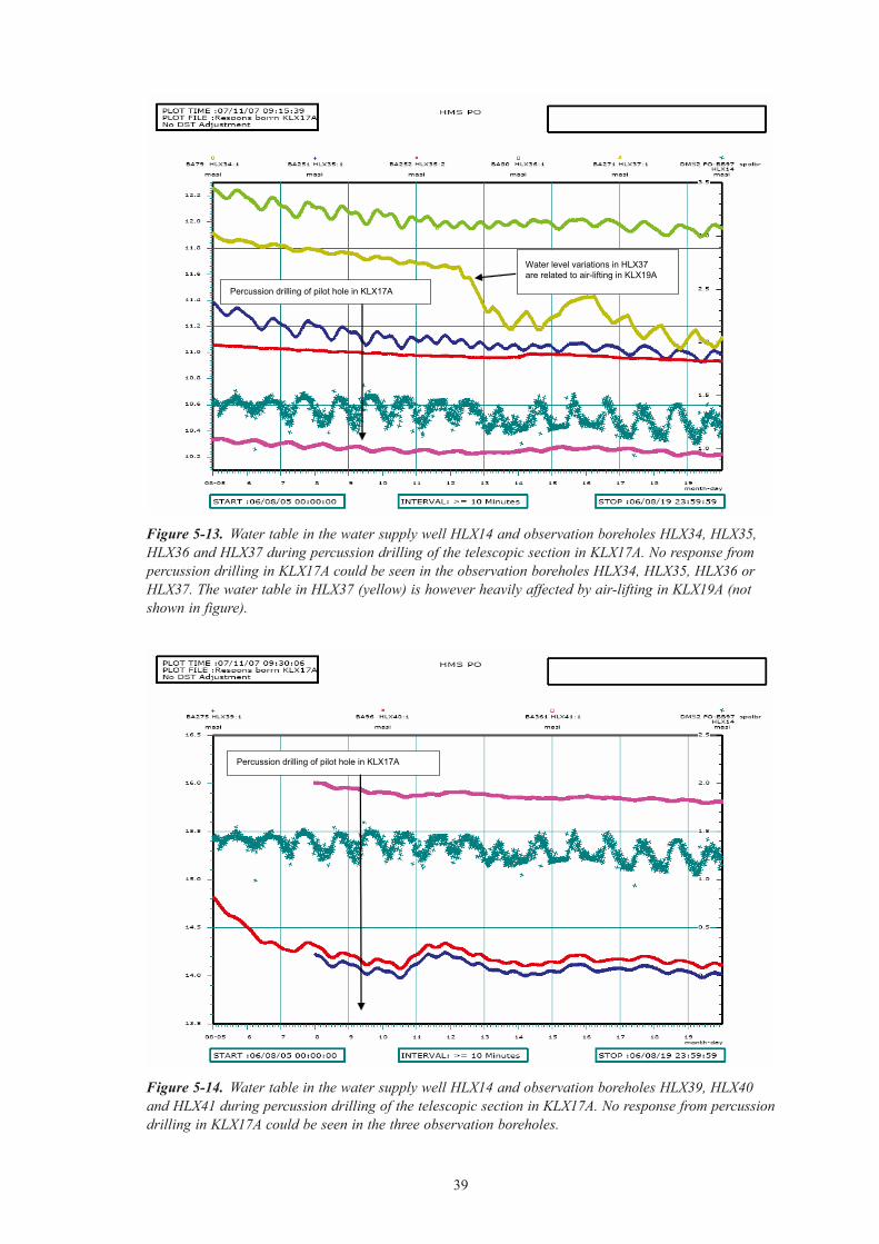
Hydraulic responses from an interference test (i.e. pumping in KLX17A) on October 28–29 could be seen in HLX39, HLX40 and the upper most section in KLX13A, see Figure 5-18 and 5-19 respectively.
Hydraulic responses in near-by boreholes from nitrogen gas flushing in KLX17A
Lifting with nitrogen gas covering the entire length of the borehole was done five times on November 5.
A weak hydraulic response from nitrogen lifting in KLX17A could be seen in the upper parts of KLX13A, see Figure 5-20.
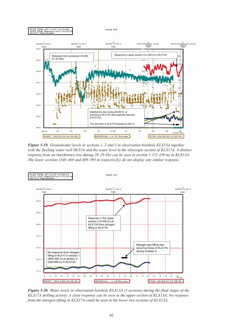
No hydraulic responses related to the nitrogen lifting in KLX17A could be seen in observation boreholes KLX20A, HLX38, HLX39, HLX40 or HLX41, see Figures 5-21 and 5-22.
No plots are presented here from observation boreholes KLX04, KLX06, HLX34, HLX35, HLX36, HLX37, but no hydraulic responses could be seen in these boreholes.
Data from the water table in the flushing water well HLX14 or the telescopic section of KLX17A were not available as the DMS system was closed after the borehole was completed. No data from KLX08 and KLX11A were available.
The location of the observation boreholes, water supply well and KLX17A is given in Figure 5-23.
39
Figure 5-13. Water table in the water supply well HLX14 and observation boreholes HLX34, HLX35, HLX36 and HLX37 during percussion drilling of the telescopic section in KLX17A. No response from percussion drilling in KLX17A could be seen in the observation boreholes HLX34, HLX35, HLX36 or HLX37. The water table in HLX37 (yellow) is however heavily affected by air-lifting in KLX19A (not shown in figure).
Figure 5-14. Water table in the water supply well HLX14 and observation boreholes HLX39, HLX40 and HLX41 during percussion drilling of the telescopic section in KLX17A. No response from percussion drilling in KLX17A could be seen in the three observation boreholes.
Percussion drilling of pilot hole in KLX17A
Water level variations in HLX37 are related to air-lifting in KLX19A
Percussion drilling of pilot hole in KLX17A

40
Figure 5-15. Groundwater levels in observation boreholes HLX34, HLX35, HLX36 and HLX37 together with water level in the flushing water well HLX14 and the water level in the telescopic section of KLX17A. No response can be seen from air-lifting in KLX17A in any of the observation boreholes in the figure. It should be noted that a distinct recovery in the lower section of HLX35 (blue, 65–151 m) occurred when the pumping in HLX14 was discontinued. The upper section of HLX35 (red) is not affected by the same event. HLX37 is affected by events that are completely unrelated to the drilling in KLX17A (cessation of pumping in HLX28 and pumping tests in KLX11F).
Figure 5-16. Groundwater levels in observation borehole KLX04. No responses can be seen in observation borehole KLX04 from the drilling activities in KLX17A. A clear response can however be seen in KLX04, especially in the upper sections, from pumping in KLX08 and also when pumping was stopped in HLX14.
Pumping stopped in HLX28
Nitrogen lifting in KLX19A
Pumping test in KLX11F
Pumping stopped in HLX14Drawdown from pumping in KLX0821–24 Sept.
lkjlkjl
lkkjkjkjkj
Drawdown in HLX14 from pumping in KLX08 21-24 Sept.
KLX08
lkjlkjl
lkkjkjkjkj
Drawdown in HLX14 from pumping in KLX08 21-24 Sept.
KLX08
lkjlkjl
lkkjkjkjkj
Drawdown in HLX14 from pumping in KLX08 21-24 Sept.
Precipitation
Stop pumping in HLX14
Drawdown in KLX04 from pumping in KLX08 21-24 Sept. This pumping also affects HLX14

41
Figure 5-17. Groundwater levels in sections 1–4 (the deeper sections) in observation borehole KLX11A together with water level in the flushing water well HLX14 and the water level in the telescopic section of KLX17A. No response from the drilling in KLX17A can be seen in KLX11A. There are however clear responses in KLX11A from pumping and injection in boreholes KLX11B, KLX11D and KLX11F. The response from tests in KLX11E and KLX11C is more obscure.
Figure 5-18. Groundwater levels in observation borehole HLX38, HLX39, HLX40 and HLX41 together with the flushing water well HLX14 and the water level in the telescopic section of KLX17A. A weak response from an interference test during 28–29 Oct can be seen in HLX39 and HLX40. No response from the interference test or from any other drilling related activity in KLX17A can be seen in observation boreholes HLX38 and HLX41. A response from nitrogen lifting in borehole KLX14A was however noted in HLX38.
Injection tests in KLX11D, KLX11F and KLX11B respectively
Start of pumping tests (ie drawdown phase) in KLX11B KLX11E KLX11D KLX11C KLX11F
lkjlkjl
lkkjkjkjkj
Drawdown in HLX14 from pumping in KLX08 21-24 Sept.
KLX08
lkjlkjl
lkkjkjkjkj
Drawdown in HLX14 from pumping in KLX08 21-24 Sept.
KLX08
Nitrogen lifting in KLX14A Interference test during 28–29/10 ie pumping in KLX17A with expected reponse in KLX13A.
The drill stem in KLX17A lowered to 420 m
Possible weak response in HLX39 and HLX40 from interference testDrawdown from pumping in KLX08
21–24 Sept.
42
Figure 5-19. Groundwater levels in sections 1, 2 and 3 in observation borehole KLX13A together with the flushing water well HLX14 and the water level in the telescopic section of KLX17A. A distinct response from an interference test during 28–29 Oct can be seen in section 1 (12–339 m) in KLX13A. The lower sections (340–468 and 469–595 m respectively) do not display any similar response.
Figure 5-20. Water levels in observation borehole KLX13A (3 sections) during the final stages of the KLX17A drilling activity. A clear response can be seen in the upper section of KLX13A. No response from the nitrogen lifting in KLX17A could be seen in the lower two sections of KLX13A.
The drill stem in KLX17A lowered to 420 m
lkjlkjl
lkkjkjkjkj
Drawdown in HLX14 from pumping in KLX08 21-24 Sept.
KLX08
lkjlkjl
lkkjkjkjkj
Drawdown in HLX14 from pumping in KLX08 21-24 Sept.
KLX08
lkjlkjl
lkkjkjkjkj
Response in upper section (12–339 m) in KLX13A
Interference test during 28-29/10 ie pumping in KLX17A with expected reponse in KLX13A.
Drawdown from pumping in KLX0821–24 Sept.
Reponse in the upper section (12-339 m) of KLX13A from nitrogen lifting in KLX17A
Nitrogen gas lifting was done five times in KLX17A during October 6No response from nitrogen
lifting in KLX17 in section 1 (469–595 m) or section 2 (340-468 m) in KLX13A
43
Figure 5-21. Water level in observation borehole HLX38, HLX39, HLX40 and HLX41 during nitrogen gas lifting in KLX17A. No hydraulic response can be seen in any of the observation boreholes from the nitrogen lifting in KLX17A. A distinct response occurs in HLX40 and a more subtle response occurs in HLX41 from a pump test in HLX39.
Figure 5-22. Water level in observation borehole KLX20A (logger in open borehole) during nitrogen gas lifting in KLX17A. No hydraulic response from the nitrogen lifting in KLX17A can be seen in KLX20A. The water level in KLX20A is heavily affected by a pumping test in KLX11A which lasted from 061103 to 061110.
Nitrogen gas lifting was done five times in KLX17A during October 6
Pumping test in HLX39
Pumping test in KLX11A starts.
Nitrogen gas lifting was done five times in KLX17A during October 6

44
5.5 Drilling monitoring resultsThis section presents the results from drill monitoring i.e. continuous data series of water parameters or technical drilling parameters. The two main drilling steps, the telescope section 0–65.42 metres and the core drilling section 65.42–701.08 metres are described in sections 5.2 and 5.3 respectively.
5.5.1 Drill monitoring system – DMSThe DMS database contains substantial amounts of drilling monitoring data. A selection of results primarily from the monitoring of the flushing water parameters are presented in Figures 5-24 through 5-26 below.
Selected parameters from the drill rig (MWD parameters) are presented in Appendix 1. The MWD parameters require some explanation:
• Drillabilityratio–thisparameterisdefinedaspenetrationratedividedbyfeedforce.
• Flushingwaterratio–thisisdefinedasflushingwaterflowdividedbyflushingwaterpressure.
• Waterpressure(ofthewaterenteringthedrillstem).
Figure 5-23. Map showing the location of cored boreholes KLX04, KLX08, KLX11A, KLX13A, KLX17A and KLX20A and the percussion boreholes HLX27, HLX28, HLX32, HLX36 and HLX37.
45
• Flushingwaterflow(flowofingoingwater).
• Penetrationrate(rateofdrillbitpenetrationasmeasuredonthesurfaceonthedrillstem).
• Hydraulicindication–thisparameterisdefinedaspenetrationratedividedbyflushingwaterflow.
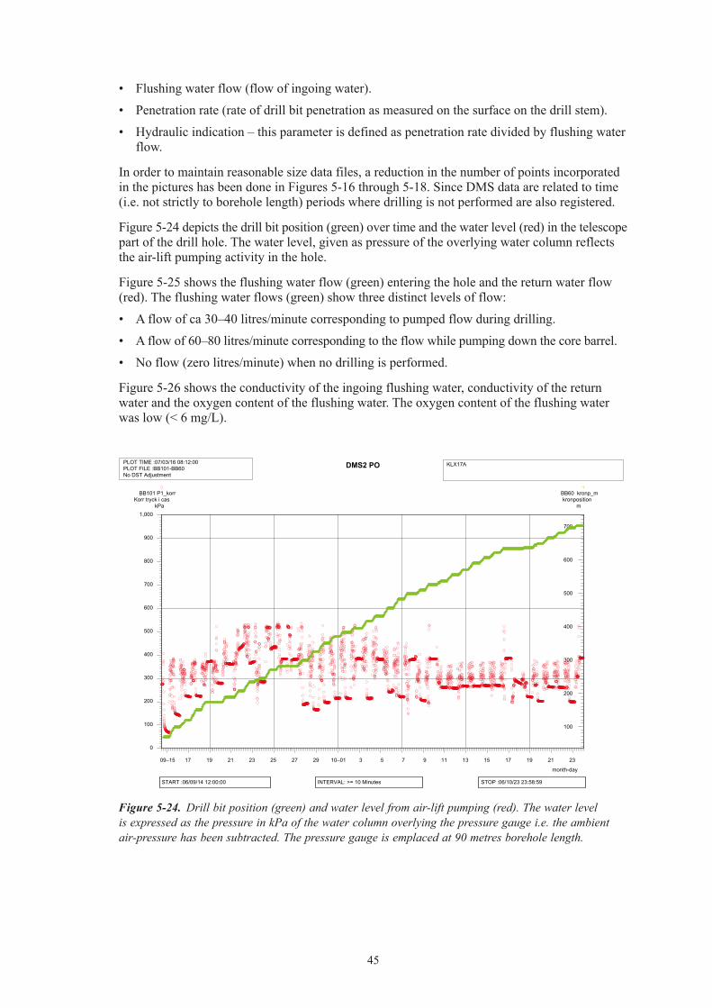
In order to maintain reasonable size data files, a reduction in the number of points incorporated in the pictures has been done in Figures 5-16 through 5-18. Since DMS data are related to time (i.e. not strictly to borehole length) periods where drilling is not performed are also registered.
Figure 5-24 depicts the drill bit position (green) over time and the water level (red) in the telescope part of the drill hole. The water level, given as pressure of the overlying water column reflects the air-lift pumping activity in the hole.
Figure 5-25 shows the flushing water flow (green) entering the hole and the return water flow (red). The flushing water flows (green) show three distinct levels of flow:
• Aflowofca30–40litres/minutecorrespondingtopumpedflowduringdrilling.
• Aflowof60–80litres/minutecorrespondingtotheflowwhilepumpingdownthecorebarrel.
• Noflow(zerolitres/minute)whennodrillingisperformed.
Figure 5-26 shows the conductivity of the ingoing flushing water, conductivity of the return water and the oxygen content of the flushing water. The oxygen content of the flushing water was low (< 6 mg/L).
DMS2 POPLOT TIME :07/03/16 08:12:00PLOT FILE :BB101-BB60No DST Adjustment
KLX17A
month-day
09–15 17 19 21 23 25 27 29 10–01 3 5 7 9 11 13 15 17 19 21 23
START :06/09/14 12:00:00 INTERVAL: >= 10 Minutes STOP :06/10/23 23:58:59
0
100
200
300
400
500
600
700
800
900
1,000
BB101 P1_korrKorr tryck i cas
kPa
100
200
300
400
500
600
700
BB60 kronp_mkronposition
m
Figure 5-24. Drill bit position (green) and water level from air-lift pumping (red). The water level is expressed as the pressure in kPa of the water column overlying the pressure gauge i.e. the ambient air-pressure has been subtracted. The pressure gauge is emplaced at 90 metres borehole length.

46
DMS2 POPLOT TIME :07/03/16 09:00:01PLOT FILE :MB8-MB46No DST Adjustment
KLX17A
month-day09–15 17 19 21 23 25 27 29 10–01 3 5 7 9 11 13 15 17 19 21 23
START :06/09/14 12:00:00 INTERVAL: >= 10 Minutes STOP :06/10/23 23:58:59
0
20
40
60
80
100
120
140
MB8 Q_OutQ_Out Flvde retu
l/mi
MB46 Q_inSpolvattenflvde
l/m
DMS2 POPLOT TIME :07/03/16 08:55:54PLOT FILE :MB7-MB-9-MB10No DST Adjustment
KLX17A
month-day09–15 17 19 21 23 25 27 29 10–01 3 5 7 9 11 13 15 17 19 21 23
START :06/09/14 12:00:00 INTERVAL: >= 10 Minutes STOP :06/10/23 23:58:59
0
2
4
6
8
10
12
14
MB7 O2_InO2_In Syrgashalt
mg/l
50
100
150
200
250
300
350
400
450
500
MB9 ElC_OutKonduktivitet Ut
mS/m
MB10 ElC_InKonduktivitet In
mS/m
Figure 5-25. Flushing water flow (green) and return water flow (red) in litres per minute.
Figure 5-26. Conductivity of flushing water (yellow) and return water (green). The oxygen content in mg/L of the flushing water (red) is also shown. The oxygen content of the flushing water is low (< 6 mg/L). The conductivity of the return water (green) is also low, typically less than 100 mS/m.

47
5.5.2 Measurements of flushing water and drill cuttingsA calculation of accumulated amounts of water flowing in and out of the borehole based on water flow measurements from the DMS system (continuous readings) is given in Figure 5-27.
The amount of flushing water consumed during drilling was 630 m3, giving an average consumption of 1 m3 per metre core drilled. The amount of effluent return water from drilling in KLX17A was measured by the DMS system to 1,100 m3, giving an average of ca 1.7 m3 per metre core drilled.
Drill cutting balance
The weight of cuttings in the settling containers amounted to 900 kg. The content of suspended material in the return water was 1,200 mg/L, see section 5.8 “Environmental control, monitoring of effluent water”. The amount of material in suspension carried with the return water would amount to 1,320 kg (based on 1,100 m3 of return water). The theoretical amount that should be produced from drilling with 76 mm triple tubing, with core barrel N3/50, over a length of 630 metres is 4,250 kg assuming a density of 2.7 kg/dm3. This means that 52% of the material liberated by drilling is accountable as removed from the borehole or the formation.
The recovered drill cuttings were collected in steel containers. After completion of drilling, the containers were removed from the site and emptied at an approved site.
Uranine tracer balance
The amount of introduced and recovered uranine is presented in Table 5-15. The results show that all (actually more than 100%) of the introduced amount of uranine was retrieved during drilling of KLX17A.
DMS2 POPLOT TIME :07/03/16 08:15:20PLOT FILE :Acc.volym SpolvattenbalansNo DST Adjustment
KLX17A
month-day09–15 17 19 21 23 25 27 29 10–01 3 5 7 9 11 13 15 17 19 21 23
START :06/09/14 12:00:00 INTERVAL: >= 10 Minutes STOP :06/10/23 23:58:59
0
100
200
300
400
500
600
700
800
900
1,000
1,100
BB206 V_outm3
BB208 V_inm3
Figure 5-27. The flushing water balance in KLX17A as recorded by the DMS system. The accumulated volume of the ingoing flushing water is shown in green and the outgoing return water is shown in red.

48
Table 5‑15. Balance calculation of uranine tracer in KLX17A.
Average uranine content IN (mg/L) 0.218Flushing water volume IN (m3) 630Amount uranine introduced (g) 137Average uranine content OUT (mg/L) 0.146Return water volume OUT (m3) 1,100Amount uranine recovered (g) 161
5.6 GeologyA preliminary geological mapping of the core is done as drilling progresses as part of the drilling activity. This mapping phase includes a first pass mapping of major geological features as well as RQD-logging and photodocumentation of the core.
A more detailed mapping with the Boremap method is made after measurements have been made in the borehole that can provide orientation of geological features. Boremap mapping and the related measurements are not part of the drilling activity. The results from the Boremap logging are included in this report as it represents a more complete geological record than the preliminary geological mapping.
The geological results based on the Boremap logging are shown in Appendix 1. It should be stressed that the geological description given in this report is a brief summary only. A more complete account is given in /8/.
Lithologically the core is dominated Ävrö granite with intercalations of diorite/gabbro and fine-grained diorite-gabbro. Minor amounts of fine grained granite were also noted in the borehole.
Rock alteration is mostly weak. A section with significant red staining, indicated as oxidized in Appendix, was logged from 100 to 120 m. This section also coincides with an elevated frequency of fractures as can be seen in Appendix 1.
Two sections with core losses were noted in KLX17A during the Boremap mapping: 108.70–109.50 and 111.23–111.44 m, see also Figure 5-10 in section 5.4.2. The core losses were labelled as “crushed zone”.
The average fracture frequency over the core drilled section is 1.7 (fractures/metre) expressed as open fractures. NB The fracture frequency given in Appendix 1 shows the total fracture frequency (i.e. open fractures, sealed fractures, sealed network and fractures in crushed sections).
5.7 Data handlingData collected by the drilling contractor and the SKB drill coordinators were reported in daily logs and other protocols and delivered to the Activity Leader. The information was entered to SICADA (SKB database) by database operators.
5.8 Environmental controlThe SKB routine for environmental control (SDP-301, SKB internal document) was followed throughout the activity. A checklist was filled in and signed by the Activity Leader and filed in the SKB archive.
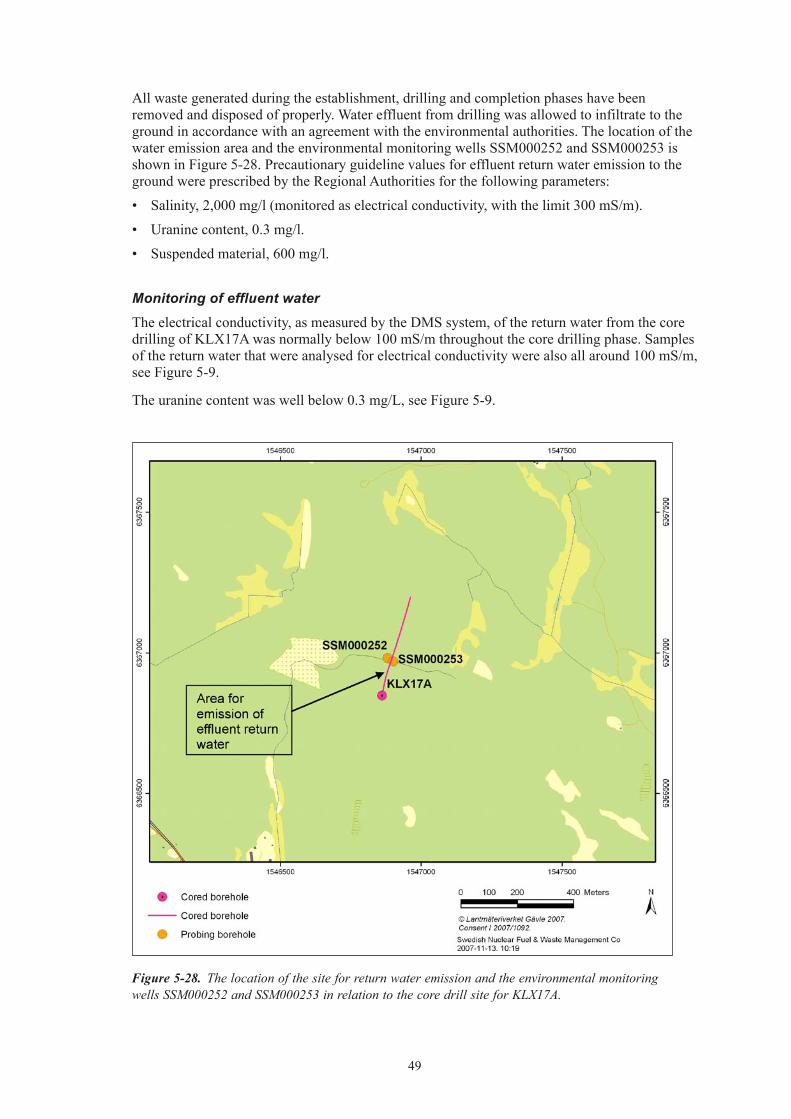
49
All waste generated during the establishment, drilling and completion phases have been removed and disposed of properly. Water effluent from drilling was allowed to infiltrate to the ground in accordance with an agreement with the environmental authorities. The location of the water emission area and the environmental monitoring wells SSM000252 and SSM000253 is shown in Figure 5-28. Precautionary guideline values for effluent return water emission to the ground were prescribed by the Regional Authorities for the following parameters:
• Salinity,2,000mg/l(monitoredaselectricalconductivity,withthelimit300mS/m).
• Uraninecontent,0.3mg/l.
• Suspendedmaterial,600mg/l.
Monitoring of effluent water
The electrical conductivity, as measured by the DMS system, of the return water from the core drilling of KLX17A was normally below 100 mS/m throughout the core drilling phase. Samples of the return water that were analysed for electrical conductivity were also all around 100 mS/m, see Figure 5-9.
The uranine content was well below 0.3 mg/L, see Figure 5-9.
Figure 5-28. The location of the site for return water emission and the environmental monitoring wells SSM000252 and SSM000253 in relation to the core drill site for KLX17A.

50
The concentration of suspended material in the return water from drilling was analysed in the borehole KLX17A. On average, the amount of suspended material from the sampling campaign in KLX17A was 1,200 mg/L. The results are given in Table 5-16. The analysed amounts were thereby considerably greater than the stipulated guidelines for emission, 600 mg/L. The analytical results were received at the time when drilling was completed in KLX17A. Changes in the handling of the return water were initiated in the last planned borehole, KLX15A as a direct result of the sampling in KLX17A (SKB id 1091530, internal document).
Environmental monitoring wells and reference sampling
Two environmental monitoring wells, SSM000252 and SSM000253, were drilled as part of the core drilling activity for KLX17A. The technical specifications are given in Appendix 6.
Reference samples of the surface soil and ground water, before drill start and establishment of the drill site were taken as given in Table 5-17.
Table 5‑16 Analysis of suspended material in return water from drilling of KLX17A.
Date and time Drilled length (m)
Sample number
Suspended material in return water (mg/l)
2006-09-29 10:30 336.42 11444 1,7002006-09-29 16:44 348.70 11445 1,8002006-09-30 08:16 354.88 11446 9302006-09-30 14:05 366.61 11447 1,5002006-10-01 07:40 372.70 11448 6002006-10-01 11:01 381.77 11449 1,6002006-10-02 08:38 387.83 11450 6502006-10-02 11:34 393.91 11451 1,3002006-10-03 10:18 399.96 11452 5302006-10-03 13:37 406.06 11453 1,5002006-10-03 15:59 412.17 11454 2,0002006-10-04 08:52 421.37 11455 1,1002006-10-04 11:05 427.49 11456 1,9002006-10-05 08:58 433.64 11457 2102006-10-05 14:03 445.87 11458 1,2002006-10-05 16:02 451.98 11459 1,6002006-10-06 07:25 457.98 11460 240
Table 5‑17. Reference samples for environmental monitoring.
Date Sample No Comment
2006-04-18 SKB PO 9011 Undisturbed soil sample2006-07-17 11223 Reference water sample in
SSM0002522006-07-17 11224 Reference water sample in
SSM000253
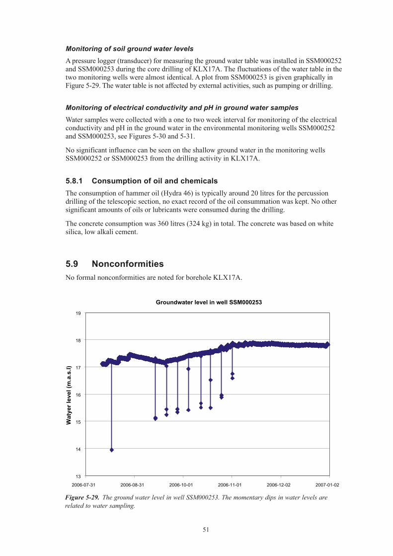
51
Monitoring of soil ground water levels
A pressure logger (transducer) for measuring the ground water table was installed in SSM000252 and SSM000253 during the core drilling of KLX17A. The fluctuations of the water table in the two monitoring wells were almost identical. A plot from SSM000253 is given graphically in Figure 5-29. The water table is not affected by external activities, such as pumping or drilling.
Monitoring of electrical conductivity and pH in ground water samples
Water samples were collected with a one to two week interval for monitoring of the electrical conductivity and pH in the ground water in the environmental monitoring wells SSM000252 and SSM000253, see Figures 5-30 and 5-31.
No significant influence can be seen on the shallow ground water in the monitoring wells SSM000252 or SSM000253 from the drilling activity in KLX17A.
5.8.1 Consumption of oil and chemicalsThe consumption of hammer oil (Hydra 46) is typically around 20 litres for the percussion drilling of the telescopic section, no exact record of the oil consummation was kept. No other significant amounts of oils or lubricants were consumed during the drilling.
The concrete consumption was 360 litres (324 kg) in total. The concrete was based on white silica, low alkali cement.
5.9 NonconformitiesNo formal nonconformities are noted for borehole KLX17A.
Figure 5-29. The ground water level in well SSM000253. The momentary dips in water levels are related to water sampling.
Groundwater level in well SSM000253
13
14
15
16
17
18
19
2006-07-31 2006-08-31 2006-10-01 2006-11-01 2006-12-02 2007-01-02
Wat
yer l
evel
(m.a
.s.l)
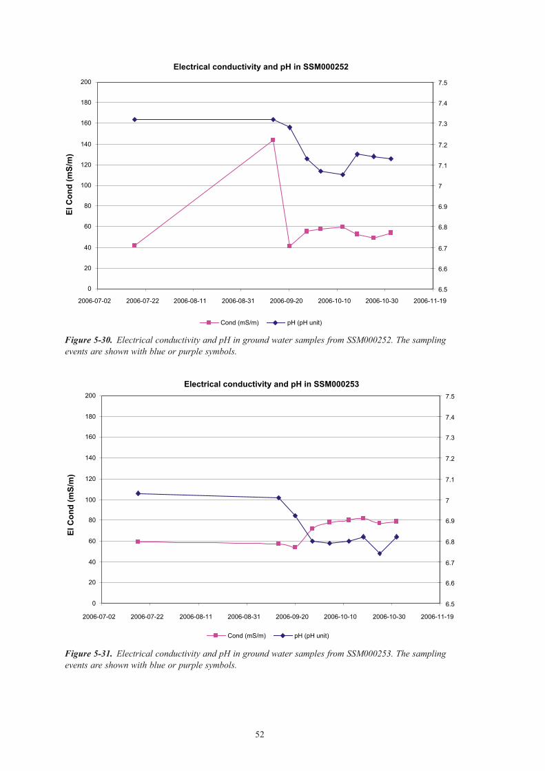
52
Figure 5-30. Electrical conductivity and pH in ground water samples from SSM000252. The sampling events are shown with blue or purple symbols.
Figure 5-31. Electrical conductivity and pH in ground water samples from SSM000253. The sampling events are shown with blue or purple symbols.
Electrical conductivity and pH in SSM000252
0
20
40
60
80
100
120
140
160
180
200
2006-07-02 2006-07-22 2006-08-11 2006-08-31 2006-09-20 2006-10-10 2006-10-30 2006-11-19
El C
ond
(mS/
m)
6.5
6.6
6.7
6.8
6.9
7
7.1
7.2
7.3
7.4
7.5
Cond (mS/m) pH (pH unit)
Electrical conductivity and pH in SSM000253
0
20
40
60
80
100
120
140
160
180
200
2006-07-02 2006-07-22 2006-08-11 2006-08-31 2006-09-20 2006-10-10 2006-10-30 2006-11-19
El C
ond
(mS/
m)
6.5
6.6
6.7
6.8
6.9
7
7.1
7.2
7.3
7.4
7.5
Cond (mS/m) pH (pH unit)

53
6 References
/1/ SKB, 2001.Platsundersökningar,Undersökningsmetoderochgenerelltgenomförande-program. SKB R-01-10, Svensk Kärnbränslehantering AB.
/2/ SKB, 2005. Platsundersökning Oskarshamn, Program för fortsatta undersökningar i mark, vatten och miljö inom delområde Laxemar. SKB R-05-37, Svensk Kärnbränslehantering AB.
/3/ Moye D G, 1967. Diamond drilling for foundation exploration, Civil Eng. Trans. Inst. Eng, Australia.
/4/ Stenberg L, Håkanson N, 2007. Revision of borehole deviation measurements in Oskarshamn. SKB P-07-55. Svensk Kärnbränslehantering AB.
/5/ Ask H, Morosini M, Samuelsson L-E, Ekström L, Håkanson N, 2005. Drilling of cored borehole KLX03. SKB P-05-167, Svensk Kärnbränslehantering AB.
/6/ Pedersen K, 2006. Double control of microorganism content in flushing water used for drilling of KLX17A. SKB P-06-309, Svensk Kärnbränslehantering AB.
/7/ Ask H, Morosini M, Samuelsson L-E and Tiberg L, 2007. Core drilling of KLX19A. SKB P-07-202, Svensk Kärnbränslehantering AB.
/8/ Mattsson K-J, Dahlin P, 2007. Boremap mapping of telescopic drilled borehole KLX17A. SKB P-07-158, Svensk Kärnbränslehantering AB.

55
Fine-grained graniteÄvrö graniteDiorite / GabbroFine-grained diorite-gabbro
OxidizedChloritisizedEpidotisizedSilicificationSaussuritization
FaintWeakMediumStrong
ROCK ALTERATION INTENSITY
Coordinate System RT90-RHB70
Length [m] 701.080
Title GEOLOGY & MWD PARAMETERS KLX17A
Elevation [m.a.s.l.] 27.63Diameter [mm] 76
Inclination [°] -61.33
Borehole KLX17A Site LAXEMAR
Northing [m] 6366848.75
Appendix 1
Easting [m] 1546862.09
Date of mapping 2006-12-06 11:49:00
ROCKTYPE LAXEMAR
Bearing [°] 11.21
Plot Date 2008-02-05 22:03:18Drilling Stop Date 2006-10-23 09:30:00Drilling Start Date 2006-08-07 07:00:00
Length
1m:1000m
LENGTH
RockType Vein Rock
Alteration Intensity CrushRock
Total FractureFreq (Fr/m)
0 40
GEOLOGY
DrillabilityRatio
-2 100
Penetration rate
0 60cm/m
FlushingWater flow
0 70l/m
WaterPressure
0 6000kPa
HydraulicIndication
0 4
FlushingWater Ratio
0 0.4
MWD PARAMETERS
80
100
120
140
160
180
200
Page 1
Appendix 1
Geology and MWD parameters KLX17A

56
220
240
260
280
300
320
340
360
380
400
420
440
460
480
Page 2

57
500
520
540
560
580
600
620
640
660
680
700
Page 3

59
Appendix 2
Chemical resultsBorehole KLX17A KLX17A
Date of measurement 2006-09-17 2006-10-05Upper section limit (m) 67.00 392.40Lower section limit (m) 187.52 430.60Sample_no 11355 11376Groundwater Chemistry Class 3 3pH 8.64 7.30Conductivity mS/m 57.5 282.0Drill water % 20.90 9.32Density g/ml 0.9973 0.9980Charge balance % –1.94 –2.41Na mg/l 105.0 419.0K mg/l 2.79 3.43Ca mg/l 14.2 87.6Mg mg/l 3.5 10.8HCO3 mg/l Alkalinity 251 68Cl mg/l 43.7 809.0SO4 mg/l 13.10 31.90SO4_S mg/l Total Sulphur 4.56 11.10Br mg/l <0.2 3.050F mg/l 4.42 2.50Si mg/l 10.80 7.89Fe mg/l Total Iron 5.050 7.880Mn mg/l 0.0816 0.2390Li mg/l 0.013 0.054Sr mg/l 0.236 2.250TOC mg/l x xPMC % Modern Carbon 50.30 29.10C-13 dev PDB –16.50 –16.30AGE_BP Groundwater age 5,460 9,865AGE_BP_CORR 40 135D dev SMOW –80.0 –120.8Tr TU –0.80 –0.80O-18 dev SMOW –10.90 –16.10B-10 B-10/B-11 0.2366 0.2349S-34 dev SMOW 27.8 31.2Cl-37 dev SMOC 0.24 –0.10Sr-87 Sr-87/Sr86 0.715482 0.715189
x = not analysed

61
Appendix 3
Chemistry – analytical method and qualitySKB Chemistry class 3
Analysis Sample bottle Preparation SKB label Laboratory
pH, conduktivity, alkalinity 250 ml green Äspö/fieldAnions (F–, Br–, Cl–, SO4
2–) 250 ml Filtered in connection with analyse
green Äspö/field
Uranine 100 ml brown glass green Äspö/fieldMain components (except Fe, Mn)
Analytica’s 100 ml acid washed
1 ml HNO3 suprapur, filtering membrane filter
red Analytica
Archive samples 2 ea 250 ml Filtering Pallfilter green
Option
Deuterium, O-18 100 ml square green IFETritium 500 ml dried Flooded at least once green WaterlooSr-87 100 ml square green IFECl-37 500 ml green WaterlooB-10 Same as for main
components1 ml HNO3 suprapur, filtering membrane filter
red Analytica
C-13, PMC 2 st 100 ml brown glass green Waterloo/Ångström S-34 1,000 ml green IFE
Quality of the analyses
The charge balance errors (see Appendix 2) give an indication of the quality and uncertainty of the analyses of the major components. The relative charge balance errors are calculated for the set of data from borehole KLX17A. The errors do not exceed ± 5% in any of the samples.
The following routines for quality control and data management are generally applied for hydrogeochemical analysis data, independent of sampling method or sampling object.
• Severalcomponentsaredeterminedbymorethanonemethodand/orlaboratory.Controlanalyses by an independent laboratory are normally performed as a standard procedure on every five or ten collected samples. No control analyses were performed on the water samples from KLX17A.
• AllanalyticalresultswerestoredintheSICADAdatabase.Thechemistrypartofthedata-base contains two types of tables, raw data tables and primary data tables (final data tables).
• Dataonbasicwateranalysesareinsertedintorawdatatablesforfurtherevaluation.Theevaluation results in a final reduced data set for each sample. These data sets are compiled in a primary data table named “water composition”. The evaluation is based on:• Comparisonoftheresultsfromdifferentlaboratoriesand/ormethods.Theanalysesare
repeated if a large disparity is noted (generally more than 10%).• Calculationofchargebalanceerrors.Relativeerrorswithin±5%areconsideredaccept-
able. For surface waters errors of ± 10%.
• Rel.Error(%)=100×(∑ cations(equivalents) – ∑ anions(equivalents)
(∑ cations(equivalents) + ∑ anions(equivalents)
• Generalexpertjudgementofplausibilitybasedonearlierresultsandexperiences.
All results from “biochemical” components and special analyses of trace metals and isotopes are inserted directly into primary data tables. In those cases where the analyses are repeated or performed by more than one laboratory, a “best choice” notation will indicate those results which are considered most reliable.

63
Appendix 4
Deviation measurements

64

65
Appendix 5
Wireline pumping tests in KLX17ADescription of the parameters in the enclosed plots
Channel Parameter Unit Description
MB30 Water flow Litre/minute Flow of water pumped up from the borehole during the test.
MB31 Electrical conductivity mS/m Electrical conductivity in the pumped out water
BB101 Pressure kPa Pressure of the water column in the telescopic section subtracted with the ambient air pressure.
BB102 Pressure kPa Pressure of the water column in the test section i.e. at depth in the borehole, subtracted with the ambient air pressure.
BB103 Pressure – section kPa Pressure of the water column in the test section i.e. at depth in the borehole, subtracted with the ambient air pressure.
MB61 Pressure – packer kPa Inflation pressure in packerMB62 Pressure – section kPa Pressure of the water column in
the test section i.e. at depth in the borehole. Not corrected for ambient air pressure
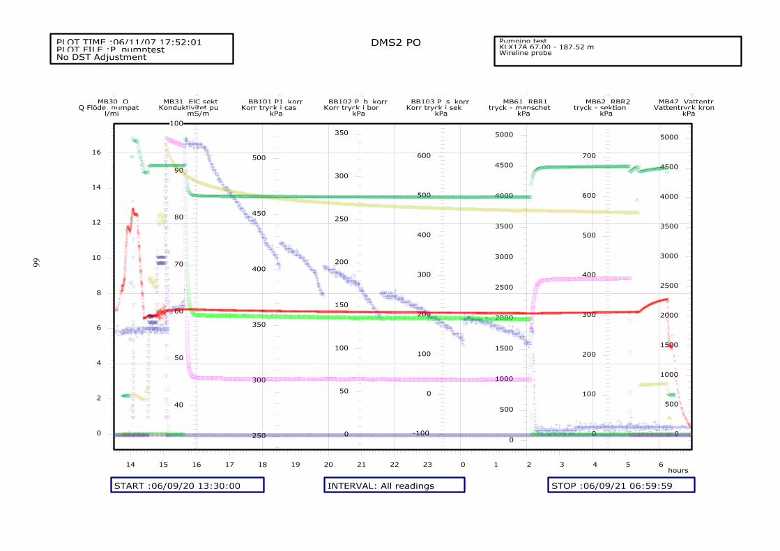
66
DMS2 POPLOT TIME :06/11/07 17:52:01PLOT FILE :P_pumptestNo DST Adjustment
Pumping test KLX17A 67.00 - 187.52 mWireline probe
hours14 15 16 17 18 19 20 21 22 23 0 1 2 3 4 5 6
START :06/09/20 13:30:00 INTERVAL: All readings STOP :06/09/21 06:59:59
0
2
4
6
8
10
12
14
16
MB30 QQ Flöde, pumpat
l/mi
40
50
60
70
80
90
100
MB31 ElC sektKonduktivitet pu
mS/m
250
300
350
400
450
500
BB101 P1_korrKorr tryck i cas
kPa
0
50
100
150
200
250
300
350
BB102 P_b_korrKorr tryck i bor
kPa
-100
0
100
200
300
400
500
600
BB103 P_s_korrKorr tryck i sek
kPa
0
500
1000
1500
2000
2500
3000
3500
4000
4500
5000
MB61 RBR1tryck - manschet
kPa
0
100
200
300
400
500
600
700
MB62 RBR2tryck - sektion
kPa
0
500
1000
1500
2000
2500
3000
3500
4000
4500
5000
MB47 VattentrVattentryck kron
kPa

67
DMS2 POPLOT TIME :06/10/27 10:36:35PLOT FILE :P_pumptestNo DST Adjustment
Pumping test KLX17A 187.00 - 280.98 mWireline probe
hours15 16 17 18 19 20 21 22 23 0 1 2 3 4 5 6 7 8
START :06/09/26 14:30:00 INTERVAL: All readings STOP :06/09/27 08:59:59
0
2
4
6
8
10
12
14
16
MB30 QQ Flöde, pumpat
l/mi
60
65
70
75
80
85
90
95
100
MB31 ElC sektKonduktivitet pu
mS/m
200
250
300
350
400
450
500
550
BB101 P1_korrKorr tryck i cas
kPa
0
50
100
150
200
250
300
350
BB102 P_b_korrKorr tryck i bor
kPa
0
200
400
600
800
1000
1200
1400
1600
1800
2000
BB103 P_s_korrKorr tryck i sek
kPa
0
500
1000
1500
2000
2500
3000
3500
4000
4500
5000
5500
6000
MB61 RBR1tryck - manschet
kPa
0
200
400
600
800
1000
1200
1400
1600
1800
2000
MB62 RBR2tryck - sektion
kPa
0
1000
2000
3000
4000
5000
6000
7000
8000
MB47 VattentrVattentryck kron
kPa

68
DMS2 POPLOT TIME :06/10/27 12:40:25PLOT FILE :P_pumptestNo DST Adjustment
Pumping test KLX17A 280.50 - 393,.91 mWireline probe
hours14 15 16 17 18 19 20 21 22 23 0 1 2 3 4 5 6
START :06/10/02 14:00:00 INTERVAL: All readings STOP :06/10/03 06:59:59
0
2
4
6
8
10
12
14
16
18
MB30 QQ Flöde, pumpat
l/mi
60
65
70
75
80
85
90
95
100
MB31 ElC sektKonduktivitet pu
mS/m
250
300
350
400
450
500
550
BB101 P1_korrKorr tryck i cas
kPa
0
50
100
150
200
250
300
350
BB102 P_b_korrKorr tryck i bor
kPa
0
500
1000
1500
2000
2500
BB103 P_s_korrKorr tryck i sek
kPa
0
1000
2000
3000
4000
5000
6000
7000
MB61 RBR1tryck - manschet
kPa
0
500
1000
1500
2000
2500
MB62 RBR2tryck - sektion
kPa
0
1000
2000
3000
4000
5000
6000
7000
8000
MB47 VattentrVattentryck kron
kPa

69
DMS2 POPLOT TIME :06/10/31 08:36:44PLOT FILE :P_pumptestNo DST Adjustment
Pumping test KLX17A 392,4 - 430,60 mWireline probe
hours14 15 16 17 18 19 20 21 22 23 0 1 2 3 4 5 6 7
START :06/10/04 13:45:00 INTERVAL: All readings STOP :06/10/05 07:59:59
0
2
4
6
8
10
12
14
16
18
MB30 QQ Flöde, pumpat
l/mi
60
80
100
120
140
160
180
200
220
240
260
MB31 ElC sektKonduktivitet pu
mS/m
200
250
300
350
400
450
500
BB101 P1_korrKorr tryck i cas
kPa
0
50
100
150
200
250
300
350
BB102 P_b_korrKorr tryck i bor
kPa
0
500
1000
1500
2000
2500
3000
3500
BB103 P_s_korrKorr tryck i sek
kPa
0
500
1000
1500
2000
2500
3000
3500
MB61 RBR1tryck - manschet
kPa
0
500
1000
1500
2000
2500
3000
3500
MB62 RBR2tryck - sektion
kPa
0
1000
2000
3000
4000
5000
6000
7000
8000
MB47 VattentrVattentryck kron
kPa

70
DMS2 POPLOT TIME :06/10/31 11:25:04PLOT FILE :P_pumptestNo DST Adjustment
Pumping test KLX17A 430,00- 524,00 mWireline probe
hours13 14 15 16 17 18 19 20 21 22 23 0 1 2 3 4 5 6 7
START :06/10/09 13:00:00 INTERVAL: All readings STOP :06/10/10 07:29:59
0
2
4
6
8
10
12
14
16
MB30 QQ Flöde, pumpat
l/mi
60
80
100
120
140
160
180
200
220
MB31 ElC sektKonduktivitet pu
mS/m
200
250
300
350
400
450
500
BB101 P1_korrKorr tryck i cas
kPa
0
50
100
150
200
250
300
350
BB102 P_b_korrKorr tryck i bor
kPa
0
500
1000
1500
2000
2500
3000
3500
4000
4500
BB103 P_s_korrKorr tryck i sek
kPa
0
1000
2000
3000
4000
5000
6000
7000
8000
MB61 RBR1tryck - manschet
kPa
0
500
1000
1500
2000
2500
3000
3500
4000
4500
MB62 RBR2tryck - sektion
kPa
0
1000
2000
3000
4000
5000
6000
7000
8000
MB47 VattentrVattentryck kron
kPa

71
DMS2 POPLOT TIME :06/10/31 15:02:33PLOT FILE :P_pumptestNo DST Adjustment
Pumping test KLX17A 521,62- 632,08 mWireline probe
hours14 15 16 17 18 19 20 21 22 23 0 1 2 3 4 5 6 7
START :06/10/16 14:00:00 INTERVAL: All readings STOP :06/10/17 07:59:59
0
2
4
6
8
10
12
14
16
MB30 QQ Flöde, pumpat
l/mi
60
65
70
75
80
85
90
95
MB31 ElC sektKonduktivitet pu
mS/m
200
250
300
350
400
450
500
BB101 P1_korrKorr tryck i cas
kPa
0
50
100
150
200
250
300
350
BB102 P_b_korrKorr tryck i bor
kPa
0
500
1000
1500
2000
2500
3000
3500
4000
4500
5000
5500
BB103 P_s_korrKorr tryck i sek
kPa
0
1000
2000
3000
4000
5000
6000
7000
8000
9000
MB61 RBR1tryck - manschet
kPa
0
500
1000
1500
2000
2500
3000
3500
4000
4500
5000
5500
6000
MB62 RBR2tryck - sektion
kPa
0
1000
2000
3000
4000
5000
6000
MB47 VattentrVattentryck kron
kPa

72
DMS2 POPLOT TIME :06/10/31 18:03:35PLOT FILE :P_pumptestNo DST Adjustment
Pumping test KLX17A 629,62- 701,08 mWireline probe
hours15 16 17 18 19 20 21 22 23 0 1 2 3 4 5 6
START :06/10/23 14:30:00 INTERVAL: All readings STOP :06/10/24 06:29:59
0
2
4
6
8
10
12
14
16
MB30 QQ Flöde, pumpat
l/mi
60
65
70
75
80
85
90
95
MB31 ElC sektKonduktivitet pu
mS/m
200
250
300
350
400
450
500
BB101 P1_korrKorr tryck i cas
kPa
0
50
100
150
200
250
300
350
BB102 P_b_korrKorr tryck i bor
kPa
0
1000
2000
3000
4000
5000
6000
BB103 P_s_korrKorr tryck i sek
kPa
0
1000
2000
3000
4000
5000
6000
7000
8000
9000
10000
MB61 RBR1tryck - manschet
kPa
0
1000
2000
3000
4000
5000
6000
7000
MB62 RBR2tryck - sektion
kPa
0
500
1000
1500
2000
2500
3000
3500
4000
4500
5000
5500
MB47 VattentrVattentryck kron
kPa

73
Appendix 6
Technical data from environmental monitoring wells SSM000252 and SSM000253

74