Embed Size (px)
Citation preview

Parker Hannifin CorporationPneumatic DivisionRichland, Michiganwww.parker.com/pneumatics
B216
Catalog PDN1000-3US
Parker Pneumatic
B
Rodless Cylinders Actuator Products
OSP-P Series
P1X Series
P1Z Series
GDL Series
OSP-P Series
Actuator Products – Rodless CylindersOSP-P Series
Weight (mass) kg
Cylinder series(Basic cylinder)
Weight (Mass) kg
At 0 mm stroke per 100 mm stroke
OSP-P10 0.087 0.052
OSP-P16 0.22 0.1
OSP-P25 0.65 0.197
OSP-P32 1.44 0.354
OSP-P40 1.95 0.415
OSP-P50 3.53 0.566
OSP-P63 6.41 0.925
OSP-P80 12.46 1.262
Size Comparison
P10 P16 P25 P32 P40 P50 P63 P80
Features
Characteristics Description
Type Rodless cylinder
Series OSP-P
Stroke length 5.5m (216 inches)
SystemDouble-acting, with cushions and
magnetic piston
Mounting See drawings
Air connection Threaded
Weight (mass) See table below
Installation In any position
Lubrication
Prelubricated at the factory
(additional oil mist lubrication not
required)
Option: special slow speed grease
Operating information
Operating pressure: 117 PSIG (8 bar)
Temperature range: -10°F to 80°F (14°C to 176°C)
Filtration requirements: Filtered, nonlubricated
compressed air
Material specifications
Cylinder profile Anodized aluminum
Carrier (piston) Anodized aluminum
End caps Aluminum, lacquered / plastic (P10)
Sealing bands Corrosion resistant steel
Seals NBR (Option: Fluorocarbon)
ScrewsGalvanized steel
Option: stainless steel
Dust covers, wipers Composite
Standard Features:• Double-acting with adjustable cushions
• With magnetic piston for position sensing
• Standard stroke lengths to 6000mm. Long stroke versions
available upon request
• End cap can be rotated 4 x 90° to position ports as desired
Optional Features:• Clean room cylinders
• Stainless steel screws
• Slow speed lubrication
• Fluorocarbon seals
• Single end porting
• Integrated valves
• Integrated bearing options

Parker Hannifin CorporationPneumatic DivisionRichland, Michiganwww.parker.com/pneumatics
B217
Catalog PDN1000-3US
Parker Pneumatic
B
Rodl
ess
Cylin
ders
Ac
tuat
or P
rodu
cts
OSP-
P Se
ries
P1X
Serie
sP1
Z Se
ries
GDL
Serie
s
A new generation of linear drives which can be simply and neatly integrated into any machine layout.
ORIGA SYSTEM PLUS – innovation from a proven design
A new modular linear drive system
With this second generation linear drive the OSP-P series
offers design engineers complete flexibility.
The well known ORIGA cylinder has been further developed
into a combined linear actuator, guidance and control package.
It forms the basis for the the OSP-P linear drive system.
All additional functions are designed into modular system
components which replace the previous series of cylinders.
Mounting rails on 3 sides
Mounting rails on 3 sides of the cylinder enable modular
components such as linear guides, brakes, valves, magnetic
switches etc. to be fitted to the cylinder itself. This solves
many installation problems, especially where space is limited.
The modular system concept forms an ideal basis for additional
customer-specific functions.
Stainless steel
screws optional.
End cap can be rotated to any one
of the four positions (before or after
delivery) so that the air connection
can be in any desired position.
Combined clamping
for inner and
outer sealing band
with dust cover.
Corrosion resistant steel
outer sealing band and
robust wiper system
on the carrier for use in
aggressive environments.
Proven corrosion resistant steel inner sealing band for optimum sealing and extremely low friction.
Magnetic piston as standard
- for contactless position
sensing on three sides of the
cylinder.
Optimized cylinder profile
for maximum stiffness and
minimum weight. Integral
air passages enable both air
connections to be positioned
at one end, if desired.
Low friction piston seals
for optimized running
characteristics
Adjustable end cushions
at both ends are standard.
New low profile
piston / carrier design.
Integral dovetail rails on three sides
provide many adaptation possibilities
(linear guides, magnetic switches, etc.).
Modular system components
are simply clamped on.
Dovetail cover
provided standard
Actuator Products – Rodless CylindersOSP-P Series

Parker Hannifin CorporationPneumatic DivisionRichland, Michiganwww.parker.com/pneumatics
B218
Catalog PDN1000-3US
Parker Pneumatic
B
Rodless Cylinders Actuator Products
OSP-P Series
P1X Series
P1Z Series
GDL Series
Plain Bearing Guide SLIDELINE
• Available on 16 to 80mm bore
Roller Guide POWERSLIDE
• Available on 16 to 50mm bore
Features:
• Adjustable composite slide elements
– optional integral brake
• Integrated sealing system with wiper elements to remove dirt
and lubricate the slideways
• Any length of stroke up to 5500 mm
WiperOiled felt wiper
Aluminium guide carriage
Aluminium guide rail
Slide adjustment elements
Pressure plate and adjustment screws
Grease nipple
Features:
• Anodized aluminum guide carriage with vee rollers
• Hardened steel guide rail
• Multiple guide sizes can be used on the same drive
• Max. Speed v = 3 m/s
• Integrated wiper and grease nipple
• Any length of stroke up to 3500 mm
Aluminum clamping rail
Hardened steel rail
Roller
Cover with wiper and grease nipple
Aluminum guide carriage
Actuator Products – Rodless CylindersOSP-P Series – Bearing Options

Parker Hannifin CorporationPneumatic DivisionRichland, Michiganwww.parker.com/pneumatics
B219
Catalog PDN1000-3US
Parker Pneumatic
B
Rodl
ess
Cylin
ders
Ac
tuat
or P
rodu
cts
OSP-
P Se
ries
P1X
Serie
sP1
Z Se
ries
GDL
Serie
s
Bore
10
16
25
32
40
50
63
80
Piston style
0 Standard
1 Tandem
Porting configurations†
0 Standard
1 End Face (position #5) ‡
2 Single End Ports
Seals
0 Buna-N
1 Flurocarbon
Lubrication
0 Standard
Fasteners
0 Chrome plated
1 Stainless steel
Stroke
x x x x x
Port orientation†
0 Position #2 (both ends)
1 Position #3 (both ends)
2 Position #4 (both ends)
Cushions
0 Standard
Version
0 Standard
Piston mounting
0 Standard*
1Clevis mount
Guides / Brakes
0 None
2 Slideline
3 Slideline with active brake
4 Slideline with multi brake
A Active brake (basic OSP)
E Powerslide (PSXX/25) (16, 25mm bore only)
G Powerslide (PSXX/45) (25, 32, 40mm bore only)
H Powerslide (PSXX/60) (40, 50mm bore only)
I Powerslide (PSXX/76) (50mm bore only)
M Inversion (NR30) (16 - 80mm bore only)
Additional carriages**
0 None
2 Slide / Proline
3Slide / Proline with AB
Dovetail cover
0 Standard
X No Cover
1-4 5-6 7 8 9 10 11 12-16 17 18 19 20 21 22 23 24 25
Ordering information / part numbering system for OSP-P rodless basic pneumatic series
Mounting
0 None
1 A1 type
4 B1 type
9 C1 type
Switches
0None, order switches separately
OSPP 25 0 1 0 0 0 01100 0 0 0 0 0 0 1 0 0
* For Joint Clamp connecting plate, order separately
** When selecting additional carriages, the tandem
piston option must also be selected
† Single end ports can not be rotated in the field
‡ Only available on 50mm bore
Actuator Products – Rodless CylindersOSP-P Series – Model Code
Sensors
For sensors see page B339.

Parker Hannifin CorporationPneumatic DivisionRichland, Michiganwww.parker.com/pneumatics
B220
Catalog PDN1000-3US
Parker Pneumatic
B
Rodless Cylinders Actuator Products
OSP-P Series
P1X Series
P1Z Series
GDL Series
Actuator Products – Rodless CylindersOSP-P Series – Sizing
Cylinder series(mm Ø)
Theoretical output force at 6 bar N (lb)
Actual output force FA
at 6 bar N (lb)
Max. momentsMax. loadF N (lb)
Cushionlength(mm)
Mx Nm (in lb)
MyNm (in lb)
MzNm (in lb)
OSP-P10 47 (10.6) 32 (7.2) 0.2 (1.8) 1 (8.9) 0.3 (2.7) 20 (4.5) 2.5 * (.09)
OSP-P16 120 (26.9) 78 (17.5) 0.45 (3.9) 4 (35.4) 0.5 (4.4) 120 (26.9) 11 (.43)
OSP-P25 295 (66.3) 250 (56.2) 1.5 (13.3) 15 (132.8) 3 (26.6) 300 (67.4) 17 (.67)
OSP-P32 483 (108.6) 420 (94.4) 3 (26.6) 30 (265.5) 5 (44.3) 450 (101.2) 20 (.79)
OSP-P40 754 (169.5) 640 (143.9) 6 (53.1) 60 (531) 8 (70.8) 750 (168.6) 27 (1.06)
OSP-P50 1178 (264.8) 1000 (224.8) 10 (88.5) 115 (1017.8) 15 (132.8) 1200 (269.8) 30 (1.18)
OSP-P63 1870 (420.4) 1550 (348.5) 12 (106.2) 200 (1771) 24 (212.4) 1650 (370.9) 32 (1.26)
OSP-P80 3016 (678) 2600 (584.5) 24 (212.4) 360 (3186) 48 (424.8) 2400 (539.5) 39 (1.54)
When sizing an OSP cylinder, consideration must be given to:
• Loads, forces and moments
• Performance of the pneumatic end cushions. The main
factors are the mass to be cushioned and the piston speed
(unless external cushioning is used, e. g. hydraulic shock
absorbers)
To determine the maximum values for light, shock-free
operation, which must not be exceeded even in dynamic
operation.
Load and moment data are based on speeds v ≤ 0.5 m/s.
When working out the action force required, it is essential to
take into account the friction forces generated by the specific
application or load.
Determine the moving mass and follow the chart below to
determine the maximum cylinder velocity.
Alternatively, take your desired velocity and moving mass to
determine the required cylinder diameter.
If these maximum permissible values are exceeded, additional
shock absorbers must be used.
For sizing a basic cylinder, use the adjacent chart. To size a
cylinder with guide bearing, use the charts on the following
page.
The peak piston velocity can be determined by assuming it
is 50% greater than the average velocity. The peak velocity
should be used in sizing the cylinder cushions.
M = F ·l
Bending moments are calculated from the center of the linear
actuator
* A rubber element (non-adjustable) is used for end cushioning.
To deform the rubber element enough to reach the absolute end position would require a Dp of 4 bar!
* For cylinders with linear guides or brakes, please be sure to take the mass of
the carriage or the brake housing into account.
0.10.1
0.20.30.40.5
1
2345
m/s
0.2 0.3 0.5 1 2 3 5 10 100 1000 kg
Max
. per
mis
sib
le p
isto
n sp
eed
at
sta
rt o
f cu
shio
ning
Mass to be cushioned *
Fz
Mz
My
MxI
I
Cushioning diagram
The sum total of each of these types of moments, divided by
each of the maximum values, determines a Load-Moment
Factor (LMF) should be equal to or less than 1.0. On horizontal
mountings, the total load (L) should also be divided by the
maximum load allowable and factored into the equation.
Loads, forces and moments
Horizontal Mountings:
Vertical Mountings:

Parker Hannifin CorporationPneumatic DivisionRichland, Michiganwww.parker.com/pneumatics
B221
Catalog PDN1000-3US
Parker Pneumatic
B
Rodl
ess
Cylin
ders
Ac
tuat
or P
rodu
cts
OSP-
P Se
ries
P1X
Serie
sP1
Z Se
ries
GDL
Serie
s
Actuator Products – Rodless CylindersOSP-P Series – Sizing
Stroke up to 5500 mm (longer strokes on request)
Stroke up to 3500 mm
The table shows the maximum permissible values for smooth
operation, which should not be exceeded even under dynamic
conditions.
The load and moment figures apply to speeds v < 0.2 m/s.
Series
Forlineardrive
Max. moments (Nm) Max. loads (N) Mass of linear drive with guide (kg)
Mx My Mz Fy, FzWith 0mm stroke
Increase per 100mm stroke
Mass * of guidecarriage (kg)
SL16 OSP-P16 6 11 11 325 0.57 0.22 0.23
SL25 OSP-P25 14 34 34 675 1.55 0.39 0.61
SL32 OSP-P32 29 60 60 925 2.98 0.65 0.95
SL40 OSP-P40 50 110 110 1500 4.05 0.78 1.22
SL50 OSP-P50 77 180 180 2000 6.72 0.97 2.06
SL63 OSP-P63 120 260 260 2500 11.66 1.47 3.32
SL80 OSP-P80 120 260 260 2500 15.71 1.81 3.32
Technical data
* Add the mass of the guide carriage to the mass to be cushioned.
* Add the mass of the guide carriage to the mass to be cushioned.
* Please note: In the cushioning diagram, add the mass of the guide
carriage to the mass to be cushioned.
SLIDELINE loads, forces and moments
POWERSLIDE loads, forces and moments
Technical data
The table shows the maximum permissible values for smooth
operation, which should not be exceeded even under dynamic
conditions.
For further information and technical data see linear drives
OSP-P.
Series
For linear drive
Max. moments (Nm) Max. load (N) Mass of linear drive with guide (kg)
Mass * of guide carriage (kg)Mx My Mz Fy, Fz
With 0 mm stroke
Increase per 100mm stroke
PS 16/25 OSP-P16 14 45 45 1400 0.93 0.24 0.7
PS 25/25 OSP-P25 14 63 63 1400 1.5 0.4 0.7
PS 25/35 OSP-P25 20 70 70 1400 1.7 0.4 0.8
PS 25/44 OSP-P25 65 175 175 3000 2.6 0.5 1.5
PS 32/35 OSP-P32 20 70 70 1400 2.6 0.6 0.8
PS 32/44 OSP-P32 65 175 175 3000 3.4 0.7 1.5
PS 40/44 OSP-P40 65 175 175 3000 4.6 1.1 1.5
PS 40/60 OSP-P40 90 250 250 3000 6 1.3 2.2
PS 50/60 OSP-P50 90 250 250 3000 7.6 1.4 2.3
PS 50/76 OSP-P50 140 350 350 4000 11.5 1.8 4.9
Example: PS 25/35
width of guide rail (35 mm)
size of drive OSP-P25

Parker Hannifin CorporationPneumatic DivisionRichland, Michiganwww.parker.com/pneumatics
B222
Catalog PDN1000-3US
Parker Pneumatic
B
Rodless Cylinders Actuator Products
OSP-P Series
P1X Series
P1Z Series
GDL Series
Actuator Products – Rodless CylindersOSP-P Series – Sizing
To avoid excessive bending and oscillation of the cylinder,
intermediate supports may be required. The diagrams below
show the maximum permissible support spacing based upon
load.
Bending up to 0.5 mm is permissible between supports. The
intermediate supports are clamped to the dovetail profile and
support the cylinder tube axially.
D 10
D 16
D 25
D 32
N
100
200
300
400
500
1.0 1.5 2.5 m2.0
Load
F
Basic cylinder 10 to 32mm bore
intermediate supports
SLIDELINE 16 to 32mm bore
intermediate supports
0.2
200400600800
100012001400160018002000220024002600
0.4 0.6 0.8 1.2 1.4 1.6 1.81 2 2.2 2.4 2.6 3.2 3.4 3.6 m2.8 3
N
D 40
D 50
D 63
D 0
Load
FBasic cylinder 40 to 80mm bore
intermediate supports
SLIDELINE 40 to 80mm bore
intermediate supports
Intermediate supports
For cylinders with guide bearings, distinguish between loading
scenario 1 and loading scenario 2.
See accessories section for intermediate support dimensions
and part numbers
Distance between supports k
Distance between supports k
Load
F
Load
F
Distance between supports k
Distance between supports k
SL 16 Loading 1SL 16 Loading 2SL 25 Loading 2SL 25 Loading 1SL 32 Loading 2SL 32 Loading 1
SL40 Loading 2 SL40 Loading 1 SL50 Loading 2 SL50 Loading 1 SL63 Loading 2 SL63 Loading 1 SL80 Loading 2 SL80 Loading 1
Loading 1 Loading 2

Parker Hannifin CorporationPneumatic DivisionRichland, Michiganwww.parker.com/pneumatics
B223
Catalog PDN1000-3US
Parker Pneumatic
B
Rodl
ess
Cylin
ders
Ac
tuat
or P
rodu
cts
OSP-
P Se
ries
P1X
Serie
sP1
Z Se
ries
GDL
Serie
s
Actuator Products – Rodless CylindersOSP-P Series – Sizing
0. 0. 0. 1.0
1.1
1.2
2.5
2.2
2.6
2.3
2.0
2.1
2.2.4
2.1.3
1.4
1.5
1.6
1. 1. 1.
0
500
1000
1500
2000
2500
3500
4000
3000
Distance between supports k
Load
F
PS 50/60 Loading 1PS 50/60 Loading 2
PS 50/76 Loading 1PS 50/76 Loading 2
0.5
0.6
0. 0. 0. 1.0
1.1
1.2
2.2
2.3
2.0
2.1
2.4
2.5
1.3
1.4
1.5
1.6
1. 1. 1.
0
500
1000
1500
2000
2500
3000
Load
F
PS 40/44 Loading 1PS 40/44 Loading 2PS 40/60 Loading 1PS 40/60 Loading 2
Distance between supports k
0.5
0.6
0. 0. 0. 1.0
1.1
1.2
2.2
2.3
2.0
2.1
2.4
2.5
1.3
1.4
1.5
1.6
1. 1. 1.
0
500
1000
1500
2000
2500
3000
Load
F
PS 32/35 Loading 1PS 32/35 Loading 2PS 32/44 Loading 1PS 32/44 Loading 2
Distance between supports k
0.3
0.4
0.5
0.6
0. 0. 0. 1.0
1.1
1.2
2.0
2.1
2.2
1.3
1.4
1.5
1.6
1. 1. 1.
0
500
1000
1500
2000
2500
3000
Load
F
PS 16/25 Loading 1PS 16/25 Loading 2PS 25/25 Loading 1PS 25/25 Loading 2PS 25/35 Loading 1PS 25/35 Loading 2PS 25/44 Loading 1PS 25/44 Loading 2
Distance between supports k
POWERSLIDE 16/25, 25/25, 25/35,
25/44mm bore intermediate supports
POWERSLIDE 40/44, 40/60mm bore
intermediate supports
POWERSLIDE 2/35, 32/44mm bore
intermediate supports
POWERSLIDE 50/60, 50/76mm bore
intermediate supports
Parker Hannifin CorporationPneumatic DivisionRichland, Michiganwww.parker.com/pneumatics
B224
Catalog PDN1000-3US
Parker Pneumatic
B
Rodless Cylinders Actuator Products
OSP-P Series
P1X Series
P1Z Series
GDL Series
Actuator Products – Rodless CylindersOSP-P Series – Dimensions
Basic cylinder dimensions – 10mm bore
Basic cylinder dimensions – 16 to 80mm bore
Stroke
Stroke + 2 x A
Dimensions (mm)
Series A B C D E G H I J K L M N P R S W X Y Zmin CF EM EN FB FH ZZ
OSP-P10 44.5 12 19 M5 12 M3 5 6 60 8.5 22 22.5 17.5 10.5 3.4 16 22.5 31 M3 64 32 9.5 2 17 17 6
Dimensions (mm)
Series A B C D E G H I J K M O S V X Y Z BW BX BY CF EN FB FH ZZOSP-P16 65 14 30 M5 18 M3 9 5.5 69 15 23 33.2 22 16.5 36 M4 81 10.8 1.8 28.4 38 3 30 27.2 7
OSP-P25 100 22 41 G1/8 27 M5 15 9 117 21.5 31 47 33 25 65 M5 128 17.5 2.2 40 52.5 3.6 40 39.5 8
OSP-P32 125 25.5 52 G1/4 36 M6 15 11.5 152 28.5 38 59 36 27 90 M6 170 20.5 2.5 44 66.5 5.5 52 51.7 1
OSP-P40 150 28 69 G1/4 54 M6 15 12 152 34 44 72 36 27 90 M6 212 21 3 54 78.5 7.5 62 63 10
OSP-P50 175 33 87 G1/4 70 M6 15 14.5 200 43 49 86 36 27 110 M6 251 27 – 59 92.5 11 76 77 10
OSP-P63 215 38 106 G3/8 78 M8 21 14.5 256 54 63 107 50 34 140 M8 313 30 – 64 117 12 96 96 16
OSP-P80 260 47 132 G1/2 96 M10 25 22 348 67 80 133 52 36 190 M10 384 37.5 – 73 147 16.5 122 122 20
Stroke
Stroke + 2 x A
Air connection D
Cushion adjustment screw

Parker Hannifin CorporationPneumatic DivisionRichland, Michiganwww.parker.com/pneumatics
B225
Catalog PDN1000-3US
Parker Pneumatic
B
Rodl
ess
Cylin
ders
Ac
tuat
or P
rodu
cts
OSP-
P Se
ries
P1X
Serie
sP1
Z Se
ries
GDL
Serie
s
Actuator Products – Rodless CylindersOSP-P Series – Dimensions
SLIDELINE Dimensions
POWERSLIDE Dimensions
Dimensions (mm)
Series A B J M Z AA BB DB DD CF EC ED EE EG EJ EK EL EW FF FT FS GG JJ ZZ
SL 16 65 14 69 31 M4 106 88 – 30 55 36 8 40 30 – – – 22 48 55 14 36 70 8
SL 25 100 22 117 40.5 M6 162 142 M5 60 72.5 47 12 53 39 22 6 6 30 64 73.5 20 50 120 12
SL 32 125 25.5 152 49 M6 205 185 M5 80 91 67 14 62 48 32 6 6 33 84 88 21 64 160 12
SL 40 150 28 152 55 M6 240 220 M5 100 102 77 14 64 50 58 6 6 34 94 98.5 21.5 78 200 12
SL 50 175 33 200 62 M6 284 264 M5 120 117 94 14 75 56 81 6 6 39 110 118.5 26 90 240 16
SL 63 215 38 256 79 M8 312 292 – 130 152 116 18 86 66 – – – 46 152 139 29 120 260 14
SL 80 260 47 348 96 M8 312 292 – 130 169 116 18 99 79 – – – 46 152 165 29 120 260 14
For further mounting accessories
and options see accessories
section.
Stroke + 2 x AStroke
Air connection for brake (Option)
Air connection for brake (Option)
Type SL25 to SL80 Type SL16
Dimensions (mm)
Series A B Z AA BB CC CF EE EF EG FF FS FT GG JJ
PS 16/25 65 14 4xM6 120 65 47 80 49 12 35 80 21 64 64 100
PS 25/25 100 22 6xM6 145 90 47 79.5 53 11 39 80 20 73.5 64 125
PS 25/35 100 22 6xM6 156 100 57 89.5 52.5 12.5 37.5 95 21.5 73 80 140
PS 25/44 100 22 6xM8 190 118 73 100 58 15 39 116 26 78.5 96 164
PS 32/35 125 25.5 6xM6 156 100 57 95.5 58.5 12.5 43.5 95 21.5 84.5 80 140
PS 32/44 125 25.5 6xM8 190 118 73 107 64 15 45 116 26 90 96 164
PS 40/44 150 28 6xM8 190 118 73 112.5 75 15 56 116 26 109.5 96 164
PS 40/60 150 28 6xM8 240 167 89 122.5 74 17 54 135 28.5 108.5 115 216
PS 50/60 175 33 6xM8 240 167 89 130.5 81 17 61 135 28.5 123.5 115 216
PS 50/76 175 33 6xM10 280 178 119 155.5 93 20 64 185 39 135.5 160 250
2

Parker Hannifin CorporationPneumatic DivisionRichland, Michiganwww.parker.com/pneumatics
B226
Catalog PDN1000-3US
Parker Pneumatic
B
Rodless Cylinders Actuator Products
OSP-P Series
P1X Series
P1Z Series
GDL Series
2
2
Piston Options
Tandem pistons can be ordered to provide a larger mounting
footprint. This option reduces the travel of the piston. When
specifying the stroke of the cylinder, include the desired travel
+ Z dimension.
Please note Zmin dimension.
10mm bore
16 to 80mm bore
When determining port orientation, the piston carriage is
always at position 1. When a bearing system is order, the
piston carriage is at position 1 and the bearing carriage is at
position 2.
End caps can be field rotated to move port locations, excluding
single ended port configurations
Note: Single end ports and port position 5 not available on 10
to 40mm bore.
1
2
3
4
5
Port orientation
1
2
3
4
2
1
5
Dimensions (mm)
Series A Zmin
OSP-P10 44.5 64
Dimensions (mm)
Series A Z min
OSP-P16 65 81
OSP-P25 100 128
OSP-P32 125 170
OSP-P40 150 212
OSP-P50 175 251
OSP-P63 215 313
OSP-P80 260 384
Actuator Products – Rodless CylindersOSP-P Series – Options
Basic cylinder end cap positioningCylinder with guide end cap positioning
1
2
3
4
5

Parker Hannifin CorporationPneumatic DivisionRichland, Michiganwww.parker.com/pneumatics
B227
Catalog PDN1000-3US
Parker Pneumatic
B
Rodl
ess
Cylin
ders
Ac
tuat
or P
rodu
cts
OSP-
P Se
ries
P1X
Serie
sP1
Z Se
ries
GDL
Serie
s
Actuator Products – Rodless CylindersOSP-P Series – Accessories
Joint Clamp Connection ø 25-50 mm
The joint clamp connection combines two OSP-P cylinders of
the same size into a compact unit with high performance.
Features
Increased load and torque capacity
Higher driving forces
Included with Joint Clamp:
2 clamping profiles with screws
1 mounting plate
Included with Multiplex:
2 clamping profiles with screws
Clevis Mounting, ø 16-80 mm
When external guides are used, parallelism deviations can lead
to mechanical strain on the piston. This can be avoided by the
use of a clevis mounting.
In the drive direction, the mounting has very little play.
Freedom of movement is provided as follows:
• Tilting in direction of movement
• Vertical compensation
• Tilting sideways
• Horizontal compensation
Inversion Mounting, ø 16-80 mm
In dirty environments, or where there are special space
restrictions, inversion of the cylinder is recom mended.
The inversion bracket transfers the driving force to the opposite
side of the cylinder. The size and position of the mounting
holes are the same as on the standard cylinder.
Please note: Other components of the OSP system such as mid-section supports, magnetic switches and the external air passage for the 16mm bore, can still be mounted on the free side of
the cylinder.
When combining single end porting with inversion mountings,
RS magnetic switches can only be mounted directly opposite
to the external air-supply profile.
Series Order number
OSP-P16 20446
OSP-P25 20037
OSP-P32 20161
OSP-P40 20039
OSP-P50 20166
OSP-P63 20459
OSP-P80 20490
Series
Order number
Standard Stainless
OSP-P16 20462 20463
OSP-P25 20005 20092
OSP-P32 20096 20094
OSP-P40 20024 20093
OSP-P50 20097 20095
OSP-P63 20466 20467
OSP-P80 20477 20478
Series Order number
Joint clamp Multiplex
OSP-P25 20153-sssss 20035-sssss
OSP-P32 20290-sssss 20167-sssss
OSP-P40 20156-sssss 20036-sssss
OSP-P50 20292-sssss 20168-sssss
Note: sssss = stroke of cylinder
Dimensions (mm)
Series J Q T ø R HH KK LL MM NN* OO PP SS ST TT UU
OSP-P16 69 10 M4 4.5 3 34 26.6 10 1 8.5 26 28 20 10 11
OSP-P25 117 16 M5 5.5 3.5 52 39 19 2 9 38 40 30 16 21
OSP-P32 152 25 M6 6.6 6 68 50 28 2 13 62 60 46 40 30
OSP-P40 152 25 M6 – 6 74 56 28 2 13 62 60 46 – 30
OSP-P50 200 25 M6 – 6 79 61 28 2 13 62 60 46 – 30
OSP-P63 256 37 M8 – 8 100 76 34 3 17 80 80 65 – 37
OSP-P80 348 38 M10 – 8 122 96 42 3 16 88 90 70 – 42
* Dimension NN gives the possible plus and minus play in horizontal and vertical movement, which
also makes tilting sideways possible.
Series OSP-P16 to 32

Parker Hannifin CorporationPneumatic DivisionRichland, Michiganwww.parker.com/pneumatics
B228
Catalog PDN1000-3US
Parker Pneumatic
B
Rodless Cylinders Actuator Products
OSP-P Series
P1X Series
P1Z Series
GDL Series
Actuator Products – Rodless CylindersOSP-P Series – Accessories
Series AB25 to 80 for basic cylinder
Features
• Actuated by pressurization
• Released by spring actuation
• Holds position, even under changing load conditions
Note:Cannot be used in combination with intermediate supports or
position sensors.
Air connection
Pressure plate
Spring Brake lining
Brake piston
Brake housingO-ring for brake piston
Cylinder barrel OSP-P
* Please Note: The mass of the brake should be added to the total moving mass when using
the cushioning diagram.
(1 – at 6 bar
both chambers pressurized with 6 bar
– oil on the braking surface will reduce braking effectiveness
Forces and Weights (SLIDELINE Guide Required)
SeriesMax. braking force (N) (1
Brake padway (mm)
Mass (kg)
Active brake order number
Linear drive with brake
Brake*0 mm stroke
Increase per100mm stroke
AB 25 350 2.5 1.0 0.197 0.35 20806
AB 32 590 2.5 2.02 0.354 0.58 20807
AB 40 900 2.5 2.83 0.415 0.88 20808
AB 50 1400 2.5 5.03 0.566 1.50 20809
AB 63 2170 3.0 9.45 0.925 3.04 20810
AB 80 4000 3.0 18.28 1.262 5.82 20811
Active Brake (Basic Cylinder)
Series Max. brake force N (lb) 1)
Mass of linear drive with guide kg (lb)
Mass* guide carriage kg (lb)With 0 mm stroke
Increase per 100 mm stroke
MB-SL 25 470 (105.7) 2.04 (5.5) 0.39 (1.0) 1.10 (2.9)
MB-SL 32 790 (177.6) 3.82 (10.2) 0.65 (1.7) 1.79 (4.8)
MB-SL 40 1200 (269.8) 5.16 (13.8) 0.78 (2.1) 2.34 (6.3)
MB-SL 50 1870 (420.4) 8.29 (22.2) 0.97 (2.6) 3.63 (9.7)
MB-SL 63 2900 (651.9) 13.31 (35.7) 1.47 (3.9) 4.97 (13.3)
MB-SL 80 2900 (651.9) 17.36 (46.5) 1.81 (4.8) 4.97 (13.3)
1) Braking surface dry – oil on the braking surface will reduce the braking force
* In the cushioning diagram, the mass of the guide carriage has to be added to the total moving mass.
The Multi-Brake is a passive device. When the air pressure is
removed the brake is actuated and movement of the cylinder is
blocked. The brake is released by pressurization.
The high friction, wear resistant brake linings allow the
Multi-Brake to be used as a dynamic brake to stop cylinder
movement in the shortest possible time. The powerful springs
also allow the Multi-Brake to be used in applications where
non-precision positioning is required
Multi-Brake
Aluminum plain bearing
guide SLIDELINE for high
loads and moments
Springs for maximum
brake forces
Brake piston
Wear resistant brake
lining, for long service life
Sensor for
wear indication
(option)

Parker Hannifin CorporationPneumatic DivisionRichland, Michiganwww.parker.com/pneumatics
B229
Catalog PDN1000-3US
Parker Pneumatic
B
Rodl
ess
Cylin
ders
Ac
tuat
or P
rodu
cts
OSP-
P Se
ries
P1X
Serie
sP1
Z Se
ries
GDL
Serie
s
End cap mountings, ø 10-80 mm
On the face of each end cap there are four threaded holes
for mounting the actuator. The hole lay out is square, so that
the mounting can be fitted to the bottom, top or either side,
regardless of the position chosen for the air connection.
Material:
Series OSP-P10 – P32: Galvanized steel.
Series OSP-P40 – P80: Anodized aluminum.
The mountings are supplied in pairs.
Actuator Products – Rodless CylindersOSP-P Series – Accessories
Series OSP-P16 to 32: Type A1
��
��
�
��
�
��
��
��
�
Dimensions (mm)
Series E ØU AB AC AD AE AF CL DG
OSP-P10 — 3.6 12 10 14 20.2 11 1.6 18.4
OSP-P16 18 3.6 18 10 14 12.5 15 1.6 26
OSP-P25 27 5.8 27 16 22 18 22 2.5 39
OSP-P32 36 6.6 36 18 26 20 30 3 50
OSP-P40 54 9 30 12.5 24 24 38 — 68
OSP-P50 70 9 40 12.5 24 30 48 — 86
OSP-P63 78 11 48 15 30 40 57 — 104
OSP-P80 96 14 60 17.5 35 50 72 — 130
(*= Pair
Series OSP-P40 to 80: Type C1
��
��
��
�
��
���
��
�
Mounting type
Series A1 B1 C1 D1 E1
OSP-P10 0240 —
OSP-P16 20408FIL — 20434FIL 20435FIL
OSP-P25 2010 20311FIL — 20008FIL 20009FIL
OSP-P32 3010 20313FIL — 20157FIL 20158FIL
OSP-P50 — 5010FIL 20162FIL 20163FIL
OSP-P63 — 6010FIL 20451FIL 20452FIL
OSP-P80 — 8010FIL 20480FIL 20482FIL
Mounting kits can be ordered via the above part numbers.
Note: Mounting kits are provided in pairs.

Parker Hannifin CorporationPneumatic DivisionRichland, Michiganwww.parker.com/pneumatics
B230
Catalog PDN1000-3US
Parker Pneumatic
B
Rodless Cylinders Actuator Products
OSP-P Series
P1X Series
P1Z Series
GDL Series
Actuator Products – Rodless CylindersOSP-P Series
Intermediate supports, ø 10-80 mm
Note on types E1 and D1 (P16 – P80):
The intermediate supports can also be moun ted on the
underside of the actuator, in which case its distance from the
center of the actuator is different.
Actuator Products – Rodless CylindersOSP-P Series – Accessories
Series OSP-16 to 80, Type D1 Series OSP-P16 to P80: Type E1
Dimension Table (mm) – Series OSP-P16 to P80
Series R U UU AF DF DH DK DM DN DO DP DQ DR DS DT EF EM EN EQ
OSP-P16 M3 3.4 6 15 20 29.2 24 32 36.4 18 30 27 6 3.4 6.5 32 20 36.4 27
OSP-P25 M5 5.5 10 22 27 38 26 40 47.5 36 50 34.5 8 5.7 10 41.5 28.5 49 36
OSP-P32 M5 5.5 10 30 33 46 27 46 54.5 36 50 40.5 10 5.7 10 48.5 35.5 57 43
OSP-P40 M6 7 – 38 35 61 34 53 60 45 60 45 10 – 11 56 38 63 48
OSP-P50 M6 7 – 48 40 71 34 59 67 45 60 52 10 – 11 64 45 72 57
OSP-P63 M8 9 – 57 47.5 91 44 73 83 45 65 63 12 – 16 79 53.5 89 69
OSP-P80 M10 11 – 72 60 111.5 63 97 112 55 80 81 15 – 25 103 66 118 87
Series OSP-10, Type E1
Dimensions (mm) Series OSP-P10
Series U AF AH AJ AK AN
OSP-P10 3.6 11 25.4 33.4 3.5 12
Parker Hannifin CorporationPneumatic DivisionRichland, Michiganwww.parker.com/pneumatics
B231
Catalog PDN1000-3US
Parker Pneumatic
B
Rodl
ess
Cylin
ders
Ac
tuat
or P
rodu
cts
OSP-
P Se
ries
P1X
Serie
sP1
Z Se
ries
GDL
Serie
s
Actuator Products – Rodless CylindersOSP-P Series
Actuator Products – Rodless CylindersOSP-P Series – Accessories
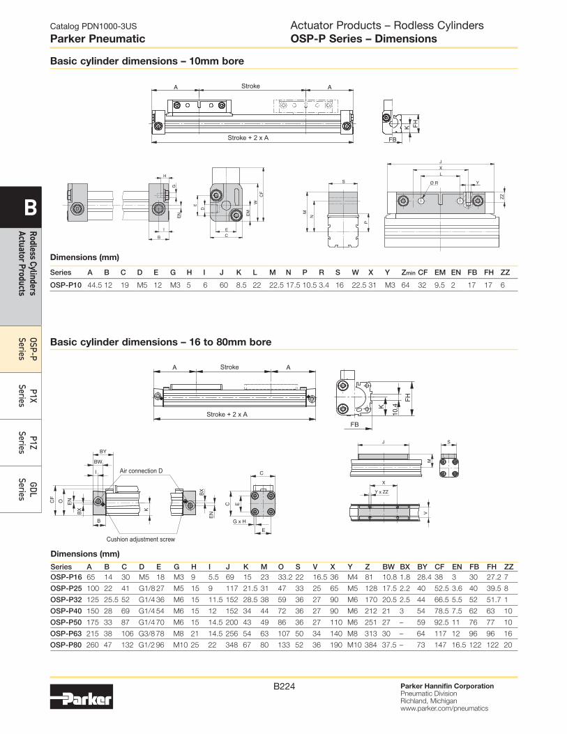
Adaptor profile, ø 16-50 mm
Adaptor profile OSP
A universal attachment for moun ting of valves etc.
Solid material
Series
Order number
Standard Stainless
OSP-P16 20432FIL 20438FIL
OSP-P25 20006FIL 20186FIL
OSP-P32 20006FIL 20186FIL
OSP-P40 20025FIL 20267FIL
OSP-P50 20025FIL 20267FIL
Series
Order number
Standard Stainless
OSP-P16 20433FIL 20439FIL
OSP-P25 20007FIL 20187FIL
OSP-P32 20007FIL 20187FIL
OSP-P40 20026FIL 20268FIL
OSP-P50 20026FIL 20268FIL
SeriesOrder number
OSP-P16 20849FIL
OSP-P25 20850FIL
OSP-P32 20850FIL
OSP-P40 20851FIL
OSP-P50 20851FIL
Connection profile, ø 16-50 mm
For combining
Series OSP-P with system profiles
Series OSP-P with Series OSP-P
T-Slot Profile ø 16-50 mm
T-slot profile OSP
A universal attachment for mounting with standard T-Nuts
Combination of Series OSP-P with system profiles
Combination of Series OSP-P with Series OSP-P
Note: Can be used in conjunction with IPS T-nut (20-058).

Parker Hannifin CorporationPneumatic DivisionRichland, Michiganwww.parker.com/pneumatics
B232
Catalog PDN1000-3US
Parker Pneumatic
B
Rodless Cylinders Actuator Products
OSP-P Series
P1X Series
P1Z Series
GDL Series
Actuator Products – Rodless CylindersOSP-P Series – Options
Heavy Duty Guide HD
for heavy duty applications
PROLINE
The compact aluminum roller guide for high loads and
velocities and utilizes the GDL Guide Bearing
STARLINE
Recirculating ball bearing guide for very high loads and
precision
SENSOFLEX SFI-plus
Incremental measuring system with 0.1 (1.0) mm resolution
Clean Room Version
Certified to DIN EN ISO 14644-1
Integrated VOE Valves
Variable Stop VS
The variable stop provides simple stroke limitation
Available on STARLINE only
Rodless Cylinder
For synchronized bi-parting movements
Available on SLIDELINE Guide Bearing only
KF Guide
Recirculating ball bearing guide – the mounting dimensions
correspond to FESTO Type: DGPL-KF
Other Options

Parker Hannifin CorporationPneumatic DivisionRichland, Michiganwww.parker.com/pneumatics
B233
Catalog PDN1000-3US
Parker Pneumatic
B
Rodl
ess
Cylin
ders
Ac
tuat
or P
rodu
cts
OSP-
P Se
ries
P1X
Serie
sP1
Z Se
ries
GDL
Serie
s
Actuator Products – Rodless CylindersOSP-P Series – Repair Kits
Service packs
Bore sizes
16mm 25mm 32mm 40mm 50mm 63mm 80mm
BUNA service pack single piston 11111xsssss 11112xsssss 11113xsssss 11114xsssss 11115xsssss 11116xsssss 11118xsssss
Fluorocarbon service pack single piston 11121xsssss 11122xsssss 11123xsssss 11124xsssss 11125xsssss 11126xsssss 11128xsssss
BUNA service pack single piston - slow speed grease 11131xsssss 11132xsssss 11133xsssss 11134xsssss 11135xsssss 11136xsssss 11138xsssss
Fluorocarbon service pack single piston - slow speed grease 11141xsssss 11142xsssss 11143xsssss 11144xsssss 11145xsssss 11146xsssss 11148xsssss
Service Pack Information
Service Packs contain all the components necessary to
completely rebuild a Parker rodless cylinder, are available.
Each pack contains a complete seal kit, inner and outer bands,
Parker grease tube, cleaning tool and repair instructions. It’s
all packaged in an easy-to-ship, easy-to-store box clearly
labeled to indicate the cylinder type, bore and stroke for which
it is intended. Contact your local Parker distributor for more
information.
Seal kits
Bore sizes
16mm 25mm 32mm 40mm 50mm 63mm 80mm
BUNA seal kit - standard cylinder 11052 11053 11054 11055 11056 11057 11058
Fluorocarbon seal kit - standard cylinder 11059 11060 11061 11062 11063 11064 11065
Seal kit - sideline carriage 11066 11067 11068 11069 11070 — —
Seal kit active brake - standard cylinder —
11822FIL 11823FIL 11824FIL 11825FIL 11826FIL 11827FIL
Seal kit - multibrake — 11089FIL 11090FIL 11091FIL 11092FIL 11093FIL —
Note: sssss = stroke of cylinder
Seal Kit Information
Seal Kits include all seals, a tube of grease, bearing shoe,
scraper and cleaning tool.

Parker Hannifin CorporationPneumatic DivisionRichland, Michiganwww.parker.com/pneumatics
B234
Catalog PDN1000-3US
Parker Pneumatic
B
Rodless Cylinders Actuator Products
OSP-P Series
P1X Series
P1Z Series
GDL Series
Operating information
Maximum pressure: 100 PSIG (7 bar)
Minimum pressure: Ø16, Ø20 bores 29 PSI (2 bar)
Ø25, Ø32, Ø40 bores 14.5 PSI (1 bar)
Ø50, Ø63 bores 7 PSI (0.5 bar)
Proof pressure: 152 PSI (10.5 bar)
Temperature range: 40°F to 140°F (5°C to 60°C)
Filtration requirements: Filtered, nonlubricated compressed air
P1X Series
Ordering Information
Construction
N Inch
M Metric
P1X N 032 D
Bore size
016 16mm
020 20mm
025 25mm
032 32mm
040 40mm
050 50mm
063 63mm
Carriage
D Double acting
Piston / Shock style
A Cushions both ends (standard)
R Cushion right end only*
L Cushion left end only*
N No cushions or shock absorbers
H Shock absorber both ends**
B Shock absorber right end only**
C Shock absorber left end only**
Seal material
N Standard
Stroke length*
Basic or options
B† Standard
W† With options
/ Special (for factory use only)
Porting options
N NPTF (Std)
G BSPP
Q BSPT** Not available with
N construction
Essential Information
Optional Features
* Stroke is ALWAYS in mm.† When “B” is specified, the remaining digits in the part
number are not necessary. If “W” is used, the remaining digits in the part number must be filled out.
†† Not available on 40, 50 and 63mm bore sizes.
D A N W N N N0500
* As viewed from port side of cylinder ** Cannot be combined with inverted carriage
-B
Series
P1X Global Rodless
Actuator Products – Rodless CylindersP1X Series
• 7 bore sizes – 16mm through 63mm
• Two port locations standard
• Large carriage for stability
• Integral sensor mounting rail
• Optional adjustable stroke and shock absorbers
Fastener Type
N Standard - zinc-plated
S Stainless steel
Sensors
For sensors see page B339.
Carriage mounting style
D Basic mount
J Inverted basic mount
A Swivel mount
G Inverted swivel mount
Mounting options
No
Foot
mount
End
mount
foot
bracket
Bottom
mount
foot
bracket
Intermediate
supports
N (std) F A†† No support
H M B†† One support
K P C†† Two supports
T R D†† Three supports

Parker Hannifin CorporationPneumatic DivisionRichland, Michiganwww.parker.com/pneumatics
B235
Catalog PDN1000-3US
Parker Pneumatic
B
Rodl
ess
Cylin
ders
Ac
tuat
or P
rodu
cts
OSP-
P Se
ries
P1X
Serie
sP1
Z Se
ries
GDL
Serie
s
Figure 1 shows the maximum allowable moments for each of
the three types of loading: pitch, roll and yaw.
The sum total of each of these types of moments, divided by
each of the maximum values, determines a Load-Moment
Factor (LMF) should be equal to or less than 1.0. On horizontal
mountings, the total load (L) should also be divided by the
maximum load allowable (Figure 2) and factored into the
equation.
Horizontal mountings:
Vertical mountings:
Figure 2
Boresize
Max. allowableload [L] N (lbs)
Max. unsupportedlength mm (in)at max. loadStd. Inverted
16 141 (32) 70 (16) 450 (17.7)
20 198 (45) 101 (23) 551 (21.7)
25 356 (81) 180 (41) 899 (35.4)
32 616 (140) 308 (70) 749 (29.5)
40 959 (218) 480 (109) 1000 (39.4)
50 1456 (331) 726 (165) 1300 (51.2)
63 2297 (522) 1148 (261) 1600 (63.0)
Figure 1
Maximum allowable moments n-m (lb-in)
Bore size
[M] [Ms] [Mv]Pitch moment Roll moment Yaw momentStd. Inverted Std. Inverted Std. Inverted
16 5 (44) 3.5 (31) 1 (9) 0.5 (4) 1 (9) 1 (9)
20 10 (89) 7 (62) 1.5 (13) 0.7 (6) 3 (27) 3 (27)
25 17 (150) 12 (106) 5 (44) 2.5 (22) 10 (89) 10 (89)
32 36 (319) 25 (221) 10 (89) 5 (44) 21 (186) 21 (186)
40 77 (682) 54 (478) 23 (204) 11.5 (102) 26 (230) 26 (230)
50 154 (1363) 108 (956) 32 (283) 16 (142) 42 (372) 42 (372)
63 275 (2434) 193 (1708) 52 (460) 26 (230) 76 (673) 76 (673)
Weight & theoretical force characteristics
BoreAreain2
Weights
Theoretical force (lbs)Weight at zero stroke Weight per 1" (25.4mm) strokeM00 MLB MLB1 At pressure (PSI)
lbs kg lbs kg lbs kg lbs kg 30 40 60 80 10016 0.31 0.70 0.3 0.73 0.3 0.77 0.4 0.07 0.03 9 12 19 25 31
20 0.49 1.15 0.5 1.19 0.5 1.28 0.6 0.10 0.04 15 20 29 39 49
25 0.84 2.21 1.0 2.43 1.1 2.43 1.1 0.15 0.07 23 30 46 61 76
32 1.26 3.31 1.5 3.53 1.6 3.75 1.7 0.20 0.09 38 50 69 100 125
40 1.96 5.29 2.4 5.51 2.5 — — 0.27 0.12 59 78 117 156 195
50 3.08 7.94 3.6 8.16 3.7 — — 0.40 0.18 91 122 182 243 304
63 4.86 13.67 6.2 14.33 6.5 — — 0.63 0.28 145 193 290 386 483
Moments
Actuator Products – Rodless CylindersP1X Series
Specifications
Model P1X (Standard w/switch)Bore size mm (inch nominal) 16 (5/8) 20 (3/4), 25 (1) 32 (1-1/4), 40 (1-1/2) 50 (2), 63 (21/2)
Port size – N series M5 (10-32) 1/8 NPT 1/4 NPT 3/8 NPT
Port size – M series M5 (10-32) 1/8 Rc 1/4 Rc 3/8 Rc
Stroke tolerance in. ±0.080 to 39" ±0.100 to 118" ±0.120 to 196"
Piston speed, *in./sec.2-80 IPS with side ports on each end (Ø16 & Ø20 bores 2-40 IPS with single end porting with 39" stroke)
(Ø25, Ø32, Ø40, Ø50 & Ø63 bores 2-40 IPS with single end porting with 78" stroke)
Cushion Air cushion standard
Lubrication Not required (if you choose to lubricate your system, continuing lubrication will be required.)
*Actual piston speed with one end port will vary depending on stroke length.

Parker Hannifin CorporationPneumatic DivisionRichland, Michiganwww.parker.com/pneumatics
B236
Catalog PDN1000-3US
Parker Pneumatic
B
Rodless Cylinders Actuator Products
OSP-P Series
P1X Series
P1Z Series
GDL Series
Basic cylinder
TC
TD
C
B
DADB
XAA
PQ
XC
XB
XD HEX SOCKETHEAD BOLT
G
HA
HB
J
L + STROKE
LL + STROKE
TA
TB
LA
HA
HB
J
E
F K STROKE
P + STROKE
EF
2 - Q4 - M
DEPTH N
DC
2 - PLUG
2 - Q(PLUG)
4 - TEDEPTH TL
M3
2
35
Part number P8S-TMA0Y
(Shown larger than actual size)
Bore (mm) A B C DA DB DC E F G HA HB J K L LL LA M N
16 1.46
(37)
0.47
(12)
1.46
(37)
0.47
(12)
0.55
(14)
0.47
(12)
0.34
(8.5)
0.35
(9)
1.06
(27)
0.24
(6)
0.55
(14)
0.69
(17.5)
2.24
(57)
5.87
(149)
5.98
(152)
0.12
(3)
5-40
(M3)
0.20
(5)
20 1.73
(44)
0.55
(14)
1.65
(42)
0.55
(14)
0.63
(16)
0.63
(16)
0.41
(10.5)
0.45
(11.5)
1.22
(31)
0.34
(8.5)
0.73
(18.5)
0.87
(22)
2.46
(62.5)
6.65
(169)
6.75
(171.5)
0.10
(2.5)
8-32
(M4)
0.26
(6.5)
Bore (mm) P PQ Q TA TB TC TD TE TL XA XB XC XD
16 5.20
(132)
0.83
(21)
10-32 NPT
(M5)
3.47
(88)
1.89
(48)
1.26
(32)
0.59
(15)
5-40
(M3)
0.20
(5)
0.91
(23)
0.43
(11)
0.26
(6.5)
0.16
(4)
20 5.83
(148)
0.97
(24.5)
1/8 NPT
(1/8 Rc)
3.94
(100)
2.36
(60)
1.50
(38)
0.71
(18)
8-32
(M4)
0.24
(6)
1.10
(28)
0.63
(16)
0.24
(6)
0.20
(5)
NOTE: Must be ordered separately when ordering sensors.
Actuator Products – Rodless CylindersP1X Series
Sensor adapter bracket
inches (mm)

Parker Hannifin CorporationPneumatic DivisionRichland, Michiganwww.parker.com/pneumatics
B237
Catalog PDN1000-3US
Parker Pneumatic
B
Rodl
ess
Cylin
ders
Ac
tuat
or P
rodu
cts
OSP-
P Se
ries
P1X
Serie
sP1
Z Se
ries
GDL
Serie
s
Basic cylinder
C
XC
XB
A
XA
DB
B
TD
XE
TC
G
HA
HB
J
E
FK STROKE
L + STROKE
LL + STROKE
TB
TA
HA
HB
J
LA
E
FP + STROKE
2 - Q
HC
DC
DD4 - MDEPTH N 2 - Q
(PLUG)
4 - TEDEPTH TL
Bore (mm) A B C DB DC DD E F G HA HB HC J K L LL LA M N
25 2.09
(53)
0.67
(17)
2.09
(53)
0.79
(20)
1.02
(26)
0.75
(19)
0.55
(14)
0.39
(10)
1.59
(40.5)
0.30
(7.5)
0.79
(20)
0.74
(18.9)
0.95
(24)
2.80
(71)
7.48
(190)
7.56
(192)
0.08
(2)
1/4-20
(M6)
0.35
(9)
32 2.60
(66)
0.73
(18.5)
2.24
(57)
1.26
(32)
1.06
(27)
0.83
(21)
0.59
(15)
0.51
(13)
1.71
(43.5)
0.39
(10)
0.93
(23.5)
0.85
(21.5)
1.10
(28)
3.35
(85)
8.90
(226)
9.00
(228.5)
0.10
(2.5)
1/4-20
(M6)
0.35
(9)
40 3.15
(80)
0.87
(22)
2.64
(67)
1.42
(36)
1.38
(35)
1.10
(28)
0.67
(17)
0.55
(14)
2.03
(51.5)
0.51
(13)
1.02
(26)
1.06
(27)
1.22
(31)
3.58
(91)
9.61
(244)
9.71
(246.5)
0.10
(2.5)
5/16-18
(M8)
0.47
(12)
50 3.78
(96)
1.10
(28)
3.23
(82)
1.77
(45)
1.38
(35)
1.38
(35)
0.91
(23)
0.63
(16)
2.40
(61)
0.59
(15)
1.30
(33)
1.39
(35.3)
1.54
(39)
3.54
(90)
10.16
(258)
10.26
(260.5)
0.10
(2.5)
5/16-18
(M8)
0.47
(12)
63 4.65
(118)
1.38
(35)
3.74
(95)
1.97
(50)
1.54
(39)
1.65
(42)
0.75
(19)
0.79
(20)
2.91
(74)
0.59
(15)
1.26
(32)
1.69
(43)
1.54
(39)
4.29
(109)
11.65
(296)
11.75
(298.5)
0.10
(2.5)
3/8-16
(M10)
0.59
(15)
Bore (mm) P Q TA TB TC TD TE TL XA XB XC XE
25 6.38
(162)
1/8 NPT
(1/8 Rc)
4.80
(122)
2.76
(70)
1.89
(48)
0.79
(20)
10-24
(M5)
0.32
(8)
1.50
(38)
0.91
(23)
0.22
(5.5)
1.58
(40)
32 7.72
(196)
1/4 NPT
(1/4 Rc)
5.28
(134)
3.15
(80)
2.21
(56)
0.79
(20)
1/4-20
(M6)
0.35
(9)
1.89
(48)
0.98
(25)
0.24
(6)
1.85
(47)
40 8.27
(210)
1/4 NPT
(1/4 Rc)
5.83
(148)
3.54
(90)
2.68
(68)
1.18
(30)
1/4-20
(M6)
0.43
(11)
2.36
(60)
1.18
(30)
0.28
(7)
2.28
(58)
50 8.35
(212)
3/8 NPT
(3/8 Rc)
5.98
(152)
3.94
(100)
3.15
(80)
1.18
(30)
5/16-18
(M8)
0.51
(13)
2.91
(74)
1.42
(36)
0.39
(10)
2.76
(70)
63 10.16
(258)
3/8 NPT
(3/8 Rc)
6.61
(168)
4.33
(110)
4.02
(102)
1.58
(40)
5/16-18
(M8)
0.51
(13)
3.78
(96)
1.65
(42)
0.55
(14)
3.54
(90)
inches (mm)
Actuator Products – Rodless CylindersP1X Series

Parker Hannifin CorporationPneumatic DivisionRichland, Michiganwww.parker.com/pneumatics
B238
Catalog PDN1000-3US
Parker Pneumatic
B
Rodless Cylinders Actuator Products
OSP-P Series
P1X Series
P1Z Series
GDL Series
TF
C
SB
SA
V
U
W + STROKE
V
U4 - MB
HEX SOCKETHEAD BOLT
4 - ØX
16 to 32 mm bore sizes
40 to 63 mm bore sizes
C
TF SB
SA
V
U
4 - ØXFCT BORE
DEPTH XG
W + STROKE
V
U
4 - ØX 4 - MBHEX SOCKETHEAD BOLT
Bore (mm) C SA SB TF U V W X XF XG MB
16 1.46
(37)
1.38
(35)
1.02
(26)
0.32
(8)
0.24
(6)
0.16
(4)
6.34
(161)
0.14
(3.6)— — M3x10
20 1.65
(42)
1.69
(43)
1.30
(33)
0.39
(10)
0.24
(6)
0.24
(6)
7.13
(181)
0.19
(4.7)— — M4x12
25 2.09
(53)
2.05
(52)
0.79
(20)
0.47
(12)
0.35
(9)
0.43
(11)
8.19
(208)
0.28
(7)— — M5x50
32 2.24
(57)
2.52
(64)
1.26
(32)
0.47
(12)
0.35
(9)
0.43
(11)
9.61
(244)
0.28
(7)— — M5x50
40 2.64
(67)
3.15
(80)
1.18
(30)
0.59
(15)
0.49
(12.5)
0.45
(11.5)
10.60
(269)
0.35
(9)
0.51
(13)
0.34
(8.7)M6x55
50 3.23
(82)
3.70
(94)
1.57
(40)
0.79
(20)
0.49
(12.5)
0.45
(11.5)
11.10
(283)
0.35
(9)
0.51
(13)
0.34
(8.7_M8x65
63 3.74
(95)
4.57
(116)
1.89
(48)
0.98
(25)
0.59
(15)
0.59
(15)
12.80
(326)
0.43
(11)
0.61
(15.5)
0.41
(10.5)M8x70
inches (mm)
Actuator Products – Rodless CylindersP1X Series

Parker Hannifin CorporationPneumatic DivisionRichland, Michiganwww.parker.com/pneumatics
B239
Catalog PDN1000-3US
Parker Pneumatic
B
Rodl
ess
Cylin
ders
Ac
tuat
or P
rodu
cts
OSP-
P Se
ries
P1X
Serie
sP1
Z Se
ries
GDL
Serie
s
TG
CTY
SA
SBV
U
V
UW + STROKE
2 - Q(PLUG)
4 - ØX
4 - MCHEX SOCKETHEAD BOLT 2 - Q
(PLUG)
16 to 20 mm bore sizes
25 to 32 mm bore sizes
C
TG
TY
SB
SAV
U
W + STROKE
UV
2 - Q(PLUG)
4 - ØX
4 - MCHEX SOCKET
HEAD BUTTONBOLT
Bore (mm) C Q SA SB TG TY U V W X MC
16 1.46
(37)
10-32
(M5)
1.38
(35)
1.02
(26)
0.24
(6)
1.69
(43)
0.24
(6)
0.16
(4)
6.34
(161)
0.13
(3.4)5-40, 1/4 LG
20 1.65
(42)
1/8 NPT
(1/8 Rc)
1.69
(43)
1.30
(33)
0.32
(8)
1.97
(50)
0.24
(6)
0.24
(6)
7.13
(181)
0.18
(4.5)8-32, 3/8 LG
25 2.09
(53)
1/8 NPT
(1/8 Rc)
1.97
(50)
0.79
(20)
0.39
(10)
2.48
(63)
0.35
(9)
0.43
(11)
8.19
(208)
0.28
(7)1/4-20 x 1/2 LG
32 2.24
(57)
1/4 NPT
(1/4 Rc)
2.52
(64)
1.26
(32)
0.39
(10)
2.64
(67)
0.35
(9)
0.43
(11)
9.61
(244)
0.28
(7)1/4-20 x 1/2 LG
40 2.64
(67)
1/4 NPT
(1/4 Rc)— — — — — — — — —
50 3.23
(82)
3/8 NPT
(3/8 Rc)— — — — — — — — —
63 3.74
(95)
3/8 NPT
(3/8 Rc)— — — — — — — — —
Actuator Products – Rodless CylindersP1X Series
inches (mm)
Parker Hannifin CorporationPneumatic DivisionRichland, Michiganwww.parker.com/pneumatics
B240
Catalog PDN1000-3US
Parker Pneumatic
B
Rodless Cylinders Actuator Products
OSP-P Series
P1X Series
P1Z Series
GDL Series
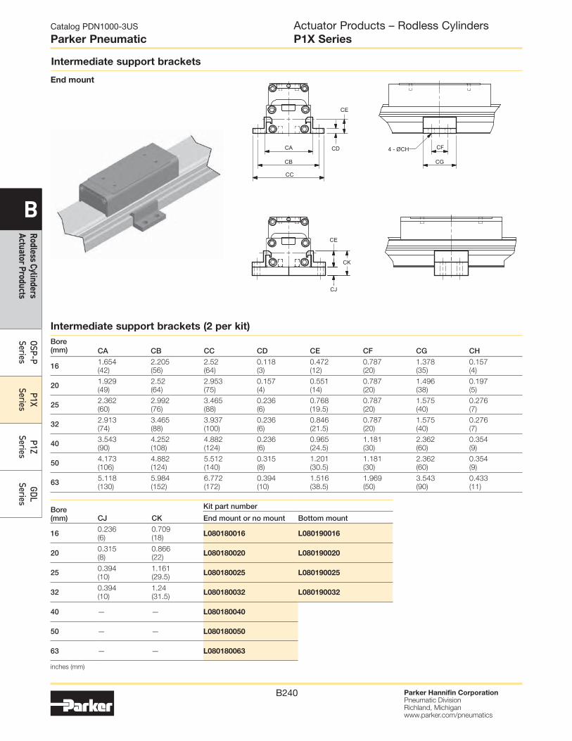
Intermediate support brackets
End mount
CA
CB
CC
CD
CE
CF
CG
4 - ØCH
CJ
CE
CK
Intermediate support brackets (2 per kit)
Bore (mm) CA CB CC CD CE CF CG CH
16 1.654
(42)
2.205
(56)
2.52
(64)
0.118
(3)
0.472
(12)
0.787
(20)
1.378
(35)
0.157
(4)
20 1.929
(49)
2.52
(64)
2.953
(75)
0.157
(4)
0.551
(14)
0.787
(20)
1.496
(38)
0.197
(5)
25 2.362
(60)
2.992
(76)
3.465
(88)
0.236
(6)
0.768
(19.5)
0.787
(20)
1.575
(40)
0.276
(7)
32 2.913
(74)
3.465
(88)
3.937
(100)
0.236
(6)
0.846
(21.5)
0.787
(20)
1.575
(40)
0.276
(7)
40 3.543
(90)
4.252
(108)
4.882
(124)
0.236
(6)
0.965
(24.5)
1.181
(30)
2.362
(60)
0.354
(9)
50 4.173
(106)
4.882
(124)
5.512
(140)
0.315
(8)
1.201
(30.5)
1.181
(30)
2.362
(60)
0.354
(9)
63 5.118
(130)
5.984
(152)
6.772
(172)
0.394
(10)
1.516
(38.5)
1.969
(50)
3.543
(90)
0.433
(11)
Bore (mm) CJ CK
Kit part number
End mount or no mount Bottom mount
16 0.236
(6)
0.709
(18)L080180016 L080190016
20 0.315
(8)
0.866
(22)L080180020 L080190020
25 0.394
(10)
1.161
(29.5)L080180025 L080190025
32 0.394
(10)
1.24
(31.5)L080180032 L080190032
40 — — L080180040
50 — — L080180050
63 — — L080180063
Actuator Products – Rodless CylindersP1X Series
inches (mm)

Parker Hannifin CorporationPneumatic DivisionRichland, Michiganwww.parker.com/pneumatics
B241
Catalog PDN1000-3US
Parker Pneumatic
B
Rodl
ess
Cylin
ders
Ac
tuat
or P
rodu
cts
OSP-
P Se
ries
P1X
Serie
sP1
Z Se
ries
GDL
Serie
s
Swivel mount
Absorbs misalignment between cylinder and load
FK dimension is the maximum
vertical float
FD
FEFH
FB
CFA
B
FC
FF
FG
4 - ØFL
FJ dimension is the maximum
horizontal float
Swivel mounts
Bore (mm) FA FB FC FD FE FF FG FH
16 2.238
(58)
0.827
(21)
1.339
(34)
0.945
(24)
0.673
(16)
1.181
(30)
1.575
(40)
0.118
(3)
20 2.638
(67)
0.984
(25)
1.535
(39)
1.181
(30)
0.787
(20)
1.575
(40)
2.205
(56)
0.157
(4)
25 3.071
(78)
0.984
(25)
1.85
(47)
1.181
(30)
0.787
(20)
1.575
(40)
2.205
(56)
0.157
(4)
32 3.74
(95)
1.496
(38)
2.185
(55.5)
1.772
(45)
1.181
(30)
1.969
(50)
2.756
(70)
0.236
(6)
40 4.134
(105)
1.496
(38)
2.441
(62)
1.772
(45)
1.181
(30)
1.969
(50)
2.756
(70)
0.236
(6)
50 4.961
(126)
1.732
(44)
2.874
(73)
2.362
(60)
1.575
(40)
2.756
(70)
3.543
(90)
0.315
(8)
63 5.472
(139)
1.732
(44)
3.11
(79)
2.362
(60)
1.575
(40)
2.756
(70)
3.543
(90)
0.315
(8)
Bore (mm) FJ FK FL B C Part number
16inches 0.118 0.118 0.134 0.472 1.457
L078930016mm 3 3 3.4 12 37
20inches 0.118 0.118 0.177 0.551 1.654 L080160020
mm 3 3 4.5 14 42 L08016M020
25inches 0.118 0.118 0.236 0.669 2.087 L080160025
mm 3 3 6 17 53 L08016M025
32inches 0.197 0.197 0.276 0.728 2.244 L080160032
mm 5 5 7 18.5 57 L08016M032
40inches 0.197 0.197 0.276 0.866 2.638 L080160040
mm 5 5 7 22 67 L08016M040
50inches 0.197 0.197 0.354 1.102 3.228 L080160050
mm 5 5 9 28 82 L08016M050
63inches 0.197 0.197 0.354 1.378 3.74 L080160063
mm 5 5 9 35 95 L08016M063
Actuator Products – Rodless CylindersP1X Series
inches (mm)

Parker Hannifin CorporationPneumatic DivisionRichland, Michiganwww.parker.com/pneumatics
B242
Catalog PDN1000-3US
Parker Pneumatic
B
Rodless Cylinders Actuator Products
OSP-P Series
P1X Series
P1Z Series
GDL Series
Inverted mount
Provides mounting surface 180° from carriage
*Inverted mounts not available with adjustable stroke, shock absorber or tube center support bracket.
**Use this part number when ordering as a separate part. When ordering with cylinder, use “C” option as part of cylinder part number.
CL
CK
CJ
CM
CN
CP
CR
CQ4 - CS
Refer to Figure 3 to determine when end port piping can
be used with various types of mountings relative to fitting
clearance.
On all bore sizes with foot mounting, the end port pipe fittings
will obstruct the mounting holes. To avoid this problem, mount
the cylinder first and tighten the mounting bolts and then
attach the pipe fittings to the cylinder ports.
Inverted mounts*
Bore (mm) CJ CK CL CM CN CP CQ CR CS Part number**
16inches 0.591 1.398 1.969 1.142 2.362 0.236 1.89 3.465 5-40 L080170016
mm 15 35.5 50 29 60 6 48 88 L08017M016
20inches 0.709 1.28 1.969 1.024 2.362 0.236 2.362 3.937 8-32 L080170020
mm 18 32.5 50 26 60 6 60 100 L08017M020
25inches 0.787 1.772 2.717 1.181 2.795 0.197 2.756 4.567 10-24 L080170025
mm 20 45 69 30.0 71 5 70 116 L08017M025
32inches 0.787 2.126 3.209 1.358 3.15 0.276 3.15 5.039 1/4-20 L080170032
mm 20 54 81.5 34.5 80 7 80 128 L08017M032
40inches 1.181 2.48 3.76 1.516 3.602 0.315 3.543 5.433 1/4-20 L080170040
mm 30 63 95.5 38.5 91.5 8 90 138 L08017M040
50inches 1.181 2.913 4.449 1.909 4.429 0.394 3.937 5.591 5/16-18 L080170050
mm 30 74 113 48.5 112.5 10 100 142 L08017M050
63inches 1.575 3.465 5.433 2.283 5.157 0.512 4.331 6.22 5/16-18 L080170063
mm 40 88 138 58 131 13 110 158 L08017M063
Figure 3
Bore (mm)
øC [O.D. of fittings - mm (in.)]No mount End mount Bottom mount
16 12 (0.472)
End Port Piping
Not Available
12 (0.472)
20 16 (0.630) 16 (0.630)
25 26 (1.024) 26 (1.024)
32 27 (1.065) 27 (1.063)
40 35 (1.378) 26 (1.024)
50 35 (1.378) 30 (1.181)
63 39 (1.535) 34 (1.339)
Actuator Products – Rodless CylindersP1X Series
End port piping

Parker Hannifin CorporationPneumatic DivisionRichland, Michiganwww.parker.com/pneumatics
B243
Catalog PDN1000-3US
Parker Pneumatic
B
Rodl
ess
Cylin
ders
Ac
tuat
or P
rodu
cts
OSP-
P Se
ries
P1X
Serie
sP1
Z Se
ries
GDL
Serie
s
Shock absorber specifications
Cylinder 16mm 20mm 25mm 32mm 40mm 50, 63mm
Shock absorber number 0887790016 0887790020 0887790025 0887790032 0887790040 0887790050
Max. energy absorption - in-lbs
(kgf·m)
26.0
(0.3)
60.8
(0.7)
104.2
(1.2)
226
(2.6)
608
(7.0)
1042
(12)
Stroke - inches 0.236 0.315 0.394 0.590 0.787 0.984
Energy absorption / hour - in.-lbs / hour 54,700 109,380 187,510 338,560 729,200 750,000
Max. impact velocity - in. / sec. 59 59 78.7 78.7 98.4 118.1
Max. cycle rate per hour 2100 1800 1800 1500 1200 720
Ambient temperature - °F (°C) 41-140 (5-60)
Spring return force - lb. Extended
Compressed
0.65
1.01
0.45
0.97
0.65
1.33
1.33
2.65
2.20
4.86
3.60
7.49
Return time - Sec. 0.3 0.3 0.3 0.3 0.4 0.4
Performance data (16 to 32mm bores)
Notes: 1. If the cylinder is vertical in orientation, double the total load for bottom shock absorber.
2. Use the total load that is being moved by shock absorber. If a weight transfer application, this would include La.
3. If final velocity cannot be easily determined, use two times the stroke divided by the stroke time.
16 mm Bore
1
10
100
1 10 100
Load (lbs)
Velo
city
(inc
hes/
sec)
20 mm Bore
1
10
100
1 10 100
Load (lbs)
Velo
city
(inc
hes/
sec)
25 mm Bore
1
10
100
1 10 100
Load (lbs)
Velo
city
(inc
hes/
sec)
32 mm Bore
1
10
100
1 10 100 1000
Load (lbs)
Velo
city
(inc
hes/
sec)
Air Cushion w/back
pressure (flow controls or
other meter out device)
Shock Absorber
Actuator Products – Rodless CylindersP1X Series
1
10
100
1 10 100 1000
Load (lbs)
40 mm Bore
Velo
city
(inc
hes/
sec)
1
10
100
1 10 100 1000
Load (lbs)
50 mm Bore
Velo
city
(inc
hes/
sec)
1
10
100
1 10 100 1000
Load (lbs)
63 mm Bore
Velo
city
(inc
hes/
sec)

Parker Hannifin CorporationPneumatic DivisionRichland, Michiganwww.parker.com/pneumatics
B244
Catalog PDN1000-3US
Parker Pneumatic
B
Rodless Cylinders Actuator Products
OSP-P Series
P1X Series
P1Z Series
GDL Series
Actuator Products – Rodless CylindersP1X Series
16 to 25 mm bore sizes
SH = max. energy absorption
SH = max. energy absorption
32 to 63 mm bore sizes
SK
ST
SR
SFSE
SC
SG
SH
SD
L + STROKE
SJ SJ
SQ
SD SC
SG
SPC
SM
SK
SRST
SESF
SM
SG L + STROKE
SC
SD
SJ SJ
C SD
SC
SG
SQ
SP
Bore(mm) SC SD SE SF
SG SHin-lbs SJ SK SP SQ SR ST C LMax Min
16 0.71
(18)
0.16
(4)
1.65
(42)
1.38
(35)
0.57
(14.5)
0.18
(4.5)26
0.98
(25)
1.93
(49)M3
1.34
(34)
0.24
(6)
0.16
(4)
1.46
(37)
5.87
(149)
20 0.89
(22.5)
0.14
(3.5)
1.89
(48)
1.57
(40)
0.57
(14.5)
0.18
(4.5)61
1.54
(39)
2.24
(57)M4
1.50
(38)
0.32
(8)
0.20
(5)
1.65
(42)
6.65
(169)
25 0.79
(20)
0.10
(2.5)
2.46
(62.5)
2.03
(51.5)
0.57
(14.5)
0.18
(4.5)104
1.97
(50)
3.03
(77)M6
1.97
(50)
0.47
(12)
0.39
(10)
2.09
(53)
7.48
(190)
Bore(mm) SC SD SE SF
SG SHin-lbs SJ SK SP SQ SR ST C LMax Min
32 0.87
(22)
0.28
(7)
2.62
(66.5)
2.19
(55.5)
1.06
(27)
0.67
(17)226
2.56
(65)
3.86
(98)M8
2.11
(53.5)
0.55
(14)
0.47
(12)
2.24
(57)
8.90
(226)
40 1.26
(32)
0.28
(7)
3.09
(78.5)
2.58
(65.5)
1.34
(34)
0.94
(24)608
2.56
(65)
4.41
(112)M10
2.50
(63.5)
0.67
(17)
0.47
(12)
2.64
(67)
9.61
(244)
50 1.50
(38)
0.32
(8)
3.90
(99)
3.15
(80)
2.17
(55)
1.77
(45)1042
2.76
(70)
5.35
(136)M12
3.05
(77.5)
0.87
(22)
0.67
(17)
3.23
(82)
10.16
(258)
63 1.50
(38)
0.32
(8)
4.41
(112)
3.68
(93.5)
1.73
(44)
1.34
(34)1042
2.76
(70)
6.22
(158)M16
3.50
(89)
0.98
(25)
0.79
(20)
3.74
(95)
11.65
(296)
inches (mm)
inches (mm)

Parker Hannifin CorporationPneumatic DivisionRichland, Michiganwww.parker.com/pneumatics
B245
Catalog PDN1000-3US
Parker Pneumatic
B
Rodl
ess
Cylin
ders
Ac
tuat
or P
rodu
cts
OSP-
P Se
ries
P1X
Serie
sP1
Z Se
ries
GDL
Serie
s
Positioning of stroke adjustment unit
(1) Moving the stroke adjustment unit.
The stroke adjustment unit can be moved by loosening the
mounting bolts.
(2) Locking of stroke adjustment unit.
After moving the stroke adjustment unit to the appropriate
position, lock it there by tightening the mounting bolts to
the torque values shown in Figure 4. Insufficient torque may
cause the stroke adjustment unit to slip out of position.
(4) Adjustment of shock absorber.
Adjust the absorption energy of the shock absorber by
changing the operating stroke of the shock absorber. This
is done by loosening the shock absorber nut and turning
the unit. When adjustment is complete, tighten the shock
absorber nut to the torque values shown in Figure 12a.
(5) Notes on usage.
The shock absorber absorbs rated energy with rated
stroke. The factory setting allows a small amount of
shock absorber stroke before it bottoms out. Readjust the
location of the shock absorber so that the complete stroke
of the absorber is utilized.
Figure 4Torque values for tightening stroke adjustment unit.
Bore size
Tightening torqueMounting bolt(lb-in)
Stroke adj. plate bolt(lb-in)
16mm 9-114-6
20mm 22-24
25mm 46-50 22-24
32mm 195-213 –
40mm 390-415 –
50, 63mm 682-735 –
(3) Stroke adjustment using the stopper bolt.
Adjust the stroke by loosening the stopper bolt nut and
turning the stopper bolt. After adjusting the stroke, tighten
the stopper bolt nut to the torque values shown in Figure 5.
When adjusting the 16-25 mm cylinders, due to the small
amount of clearance between the table and the stroke
adjustment plate, adjust the stroke by moving the complete
stroke adjustment unit.
Figure 5Torque values for tightening stopper bolt nut and shock
absorber nut.
Bore size
Tightening torqueStopper bolt nut(lb-in)
Shock absorber nut(lb-in)
16mm 10-11 12-16
20mm 22-24 26-35
25mm 73-84 40-53
32mm 195-213 66-89
40mm 390-425 195-266
50mm 682-735 487-620
63mm 1772-1914 487-620
Cylinder Stroke End
Absorption energy as set at factory:
Small margin with stroke of shock absorber.
Adjust the position of the shock absorber until the plunger of
the shock absorber is fully depressed.
Cylinder Stroke End
ø16~ø25 ø32~ø63
Actuator Products – Rodless CylindersP1X Series

Parker Hannifin CorporationPneumatic DivisionRichland, Michiganwww.parker.com/pneumatics
B246
Catalog PDN1000-3US
Parker Pneumatic
B
Rodless Cylinders Actuator Products
OSP-P Series
P1X Series
P1Z Series
GDL Series
Operating information
Maximum pressure: 100 PSIG (7 bar)
Minimum pressure: 29 PSI (2 bar)
Temperature range: 14°F to 140°F (-10°C to 60°C)
Filtration requirements: Dry, filtered compressed air to ISO
8573-1 class 3. 4. 3. or better
P1Z Series
Standard cylinder (15 positions)
P 1 Z M 00 1 6 S N 5 0 0N B F
Options (16 positions)
Ø Stroke (mm) (in)
16 0 to 1000 0 to 39.4
20 0 to 1500 0 to 59.1
32 0 to 2000 0 to 78.7
* Cylinders are supplied with mounting nuts fitted on each endplate.
Order code examples:
- P1ZM016SNN0100B Ø 16 mm bore 100 mm stroke cylinder supplied with mounting nut on each endplate
- P1ZM020SAN1000WFBN Ø 20 mm bore 1 m stroke cylinder with foot mount on each endplate
Bore
016 Ø 16 mm
020 Ø 20 mm
032 Ø 32 mm
Cushioning
N None (Ø 16 only)
A Adjustable Cushions
Strokes
0200 200 mm
1000 1000 mm
Mounting kit*
F Footmount
L Flanges
N None (std.)
Options *
B† None
W With options
M
Cylinder port type
M† Metric (Ø 16 only)
B† BSPP (Ø 20 & 32)
N NPTF (Ø 20 & 32)† Standard when “B” option is used.
N
If external lubrication is added, this must always be continued.
Technical data
Bore sizeWeights
Weight at zero stroke
Weight per 25mm of stroke
mm inch kg lbs kg lbs
16 5/8 0.28 0.62 0.01 0.02
20 3/4 0.46 1.01 0.02 0.05
32 1-1/4 1.35 2.98 0.04 0.08
• Available in 3 bores with stroke lengths up to 2000 mm
• Adjustable air cushioning is available on all cylinderS
• The load is fixed onto the mobile carriage by 4 tapped holes
• The cylinder is attached by the ends with jam nuts, flanges
or foot mounts
Actuator Products – Rodless CylindersP1Z Series - Basic Version
Specifications for P1Z series magnetically coupled rodless
Bore size mm (inch nominal) 16 (5/8) 20 (3/4) 32 (1 1/4)
Port size M5 BSPP, 10-32 NPT 1/8 BSPP, 1/8 NPT 1/8 BSPP, 1/8 NPT
Maximum stroke mm (inch) 1000 (39.4) 1500 (59.1) 2000 (78.7)
Stroke tolerance mm +1.5/-0 <=1000 +1.5/-0; >1000 +2/-0
Piston speed m/s (inch/sec) 0.1 to 0.4 (4 to 15.75)
Max. coupling force N (lbs) 157 (35) 236 (53) 703 (158)
Cushion Air cushion standard
Lubrication Not required (If you choose to lubricate your system, continuing lubrication will be required.)
Ordering information

Parker Hannifin CorporationPneumatic DivisionRichland, Michiganwww.parker.com/pneumatics
B247
Catalog PDN1000-3US
Parker Pneumatic
B
Rodl
ess
Cylin
ders
Ac
tuat
or P
rodu
cts
OSP-
P Se
ries
P1X
Serie
sP1
Z Se
ries
GDL
Serie
s
Mounting
The mobile carriage is free to rotate 360° around the
cylinder axis. This feature facilitates the adaptation of the
cylinder to various mounting arrangements.
The load must be guided by an external device.
Basic Version
External magnets(built into the carriage)
Internal magnets(on the piston)
Mobile piston
Hard anodized
aluminum
carriage
Non magnetic
stainless steel tube
(cylinder body)
Endplate
Air supply
ports
Mounting holes to attach
the load onto the carriage
The magnetic rodless cylinder is a pneumatic cylinder
featuring a mobile piston fitted with annular magnets.
The mobile carriage is also equipped with magnets to
provide magnetic coupling between the piston and carriage.
It incorporates the following features:
• end of stroke cushioning/bumpers
• mounting:
– threaded endcaps
– optional foot mount
– optional flange mount
360°
360°
CushioningØ 16 mm: non-adjustable bumper or adjustable pneumatic
cushioning
Ø 20 and 32 mm: adjustable pneumatic cushioning
Actuator Products – Rodless CylindersP1Z Series - Basic Version
Sensors
For sensors see page B339.

Parker Hannifin CorporationPneumatic DivisionRichland, Michiganwww.parker.com/pneumatics
B248
Catalog PDN1000-3US
Parker Pneumatic
B
Rodless Cylinders Actuator Products
OSP-P Series
P1X Series
P1Z Series
GDL Series
Zf
“Fx”
M = Fx * Zf
Load diagrams
Technical data
Permissible radial loads, horizontal mounting
“L”
Permissible axial loads, vertical mounting
Ø
Max. Moment M
Max. Fx*
(Nm) (in-lbs.) (N (lbs.)
16 1.2 11 112 25
20 2.5 22 175 39
32 8.5 75 450 101
ØL Max. (kg) (lbs.)
16 3 6.6
20 5 11.0
32 10 22.0
* at 7 bar
Load“La”
“L”
Xa
L = Load guided by external device
La = Direct mounting onto the cylinder
Ff = Force due to friction*
Example: Pressure: 5 bar
Fmax = 322 N for Ø 32 mm cylinder
Calculate the kinetic energy due to the load moved
Acceleration or deceleration should not exceed the magnetic coupling force of cylinder
The load must be guided by a device from outside the cylinder !
LT = Load weight + guiding device weight + force due to friction
* at 6.5 bar
!
“L”
The load must be guided by a device from outside the cylinder !
Permissible axial loads, horizontal mounting
Ø
Max. loadT
Max.XA
(kg) (lbs.) (mm) (in.)
16 5 11 122 4.8
20 10 22 142 5.6
32 24 53 174 6.8
* If force due friction is
unknown, use 0.1 × (L + La).
0
2
4
6
8
10
12
0 500 1000 1500 2000
Load
"L"
(kg)
Stroke (mm)
∅32
∅20
∅16
0
100
200
300
400
500
5 15 25 35 50Zf (mm)
Forc
e "F
x" (N
)
∅32
∅20∅16
0
50
100
150
200
250
300
350400
450
500
2 3 4 5 6 7
Pressure (Bar)
Hol
ding
For
ce (N
)
0
22
44
67
90
112
Hol
ding
For
ce (l
bs)
29 44 58 73 87 102Pressure (PSI)
∅32
∅20
∅16
0
5
10
15
20
25
30
2 3 4 5 6 7Pressure (Bar)
Load
"LT
" (k
g)
∅32
∅20
∅16
Actuator Products – Rodless CylindersP1Z Series - Basic Version

Parker Hannifin CorporationPneumatic DivisionRichland, Michiganwww.parker.com/pneumatics
B249
Catalog PDN1000-3US
Parker Pneumatic
B
Rodl
ess
Cylin
ders
Ac
tuat
or P
rodu
cts
OSP-
P Se
ries
P1X
Serie
sP1
Z Se
ries
GDL
Serie
s
Dimensions
** = Air supply Ports 4 N
D
N
2N
N
Ø P MN NN S TL
16 M5 x 0.8
(10-32)M4 x 0.7 x 6 M10 x 1 x 6
92
(3.62)
112
(4.41)
20 G 1/8
(1/8)M5 x 0.8 x 8 M20 x 1.5 x 7
115
(4.53)
143
(5.63)
32 G 1/8
(1/8)M6 x 1 x 10 M26 x 1.5 x 7
133
(5.24)
165
(6.50)
Ø A AA B ØD E Ø EH Ø EV F FV G H L LJ M N O
16 32
(1.26)
34
(1.34)
10
(0.39)
18
(0.71)
11
(0.43)
18
(0.71)
18
(0.71)
4
(0.16)
14
(0.55)
5.5
(0.22)
15.5
(0.61)
61
(2.40)
16
(0.63)
34
(1.34)
25
(0.98)
13.5
(0.53)
20 38
(1.50)
40
(1.57)
14
(0.55)
22.8
(0.90)
17
(0.67)
28
(1.10)
24
(0.94)
8
(0.31)
26
(1.02)
9.5
(0.37)
22
(0.87)
71
(2.80)
19
(0.75)
40
(1.57)
30
(1.18)
15.5
(0.61)
32 60
(2.36)
60
(2.36)
16
(0.63)
35
(1.38)
17
(0.67)
40
(1.57)
36
(1.42)
8
(0.31)
32
(1.26)
9.5
(0.37)
23
(0.91)
87
(3.43)
30
(1.18)
50
(1.97)
40
(1.57)
18.5
(0.73)
Actuator Products – Rodless CylindersP1Z Series - Basic Version

Parker Hannifin CorporationPneumatic DivisionRichland, Michiganwww.parker.com/pneumatics
B250
Catalog PDN1000-3US
Parker Pneumatic
B
Rodless Cylinders Actuator Products
OSP-P Series
P1X Series
P1Z Series
GDL Series
Mountings
Flanges
Brackets
Only on
Ø 16 mm
4 D
2
Only on
Ø 16 mm
2 D
2
* Set of 2 pcs
** Impossible mounting
Ø t L LC ØLD LE LF LH LJ LK LX LY LS LT XL XM Order code
16 2.3
(0.09)
14.8
(0.58)
8.8
(0.35)–
5.2
(0.20)
6
(0.24)
14
(0.55)
16
(0.63)
-2
(-0.08)
33
(1.30)
42
(1.65)
109.6
(4.32)
79
(3.11)
121.6
(4.79)
96.6
(3.80)PDC15-LB*
20 3
(0.12)
28
(1.10)
18
(0.71)
6.2
(0.24)–
10
(0.39)
23
(0.91)
19
(0.75)
4
(0.16)
30
(1.18)
43
(1.69)
151
(5.94)
85
(3.35)
171
(6.73)
121
(4.76)PK1A20-LB*
32 3
(0.12)
35
(1.38)
23
(0.91)
7
(0.28)–
12
(0.47)
30
(1.18)
30
(1.18)
0
(0)
46
(1.81)
62
(2.44)
179
(7.05)**
203
(7.99)** PK1A25-LB*
Ø F ØFD FW FX FY FZ T LS Order code
16 5.2
(0.20)–
42
(1.65)
33
(1.30)–
20
(0.79)
2.3
(0.09)
92
(3.62)PDC15-FH
20 –6
(0.24)
52
(2.05)
40
(1.57)
20
(0.78)
32
(1.26)
3
(0.12)
115
(4.53)PK1A20-FH
32 –7
(0.28)
80
(3.15)
64
(2.52)
28
(1.10)
44
(1.73)
5
(0.20)
133
(5.24)PK1A25-FH
Actuator Products – Rodless CylindersP1Z Series - Basic Version

Parker Hannifin CorporationPneumatic DivisionRichland, Michiganwww.parker.com/pneumatics
B251
Catalog PDN1000-3US
Parker Pneumatic
B
Rodl
ess
Cylin
ders
Ac
tuat
or P
rodu
cts
OSP-
P Se
ries
P1X
Serie
sP1
Z Se
ries
GDL
Serie
s
End of stroke
Each endplate can be fitted with an adjustable bumper or self-
compensating shock absorbers.
Optional transfer porting
Cylinder air supply is located on one end only to facilitate
cylinder installation and avoid long tube lengths for longer
strokes.
Options
The following options are available to enhance the Magnetic
Rodless cylinder functions:
• External bumpers: when low operating pressure, light loads
and short strokes.
• External hydraulic shock absorbers: recommended for
arduous applications.
• Reed and solid state sensors: provide sensing at
an adjustable position along the entire stroke of the cylinder.
Non magnetic stainless steel
(cylinder body)
Hard anodized
aluminum carriage
Endplate
Mounting holes
Rail for mounting
sensors laterally
(on one side only –
shown on rear side)
Adjustable Bumpers
(Optional: hydraulic shock
absorbers)
Ports on one side
only on one of the
endplate (transfer
porting option)
Chrome plated steel
guide rods
External magnets
(built into the
carriage)
Internal magnets
(on the piston)
Mobile piston
The magnetic rodless cylinder is a pneumatic cylinder featuring
a mobile piston with annular magnets.
The mobile carriage is also equipped with magnets to give
magnetic coupling between the piston and carriage. The
carriage slides along the main tube and is guided by two guide
rods.
It incorporates the following features:
• Built-in guide rods
• Adjustable end-of-stroke bumpers
• Optional magnetic piston sensing
• Optional transfer porting
Guidance
The guided version consists of a carriage fitted with 4 plain
bearings, guided on 2 rods.
This design provides high rigidity, accurate guidance and
smooth movement of the carriage.
Holes to mount the load
onto the carriage
Guide bushings
Actuator Products – Rodless CylindersP1Z Series - Guided Version
P1Z Series - Guided Version

Parker Hannifin CorporationPneumatic DivisionRichland, Michiganwww.parker.com/pneumatics
B252
Catalog PDN1000-3US
Parker Pneumatic
B
Rodless Cylinders Actuator Products
OSP-P Series
P1X Series
P1Z Series
GDL Series
End of stroke sensing
NPN PNP Reed Sensors type (Qty: 2)
L With rail, no sensor
N† (std.) No sensor rail
Actuator Products – Rodless CylindersP1Z Series - Guided Version
Standard cylinder (15 positions)
P 1 Z M 00 1 6 T C 5 0 0N B N
Options (16 positions)
Ø Stroke (mm) (in)
16 0 to 750 0 to 29.5
20 0 to 1000 0 to 39.4
32 0 to 1000 0 to 59.1
Note: Order Sensors separately.
Order code examples:
- P1ZM016GCN0100B Ø 16 mm bore 100 mm stroke cylinder supplied with adjustable stop
- P1ZM020GHN1000WNBL Ø 20 mm bore 1 m stroke cylinder with hydraulic shock absorbers and rail for sensors
Bore
016 Ø 16 mm
020 Ø 20 mm
032 Ø 32 mm
Function
G Guided
T Guided with transfer porting
Cushioning
C Adjustable stop
H Hydraulic shock absorber
Strokes
0200 200 mm
1000 1000 mm
Options
B† None
W With options
M
Cylinder port type
M† Metric (Ø 16 only)
B† BSPP (Ø 20 & 32)
N NPTF (Ø 20 & 32)† Standard when “B” option is
used.
L
OptionsRange
Magnetic rodless cylinder, guided version
Available in 3 diameters with possible strokes up to
1500 mm (59 in).
4 tapped mounting holes on the carriage.
Endcap mounting provided by 4
tapped and counterbored holes.
External adjustable bumpers
Can be fitted on cylinder endcaps and provide noise
reduction and adjustment at the end of stroke.
Used when light loads and short strokes.
Pneumatic air supply on one side only
(transfer porting option).
External hydraulic shock absorbers
Self-compensating hydraulic shock absorbers can
be used instead of bumpers for a greater
cushioning effect at the end of stroke.
They are recommended for
arduous applications.
Reed or solid state sensors:
A rail fitted on one side only of the cylinder provides
mounting and position adjustment of sensors.
The rail is located on same side
as the end of stroke stops.
Ordering information

Parker Hannifin CorporationPneumatic DivisionRichland, Michiganwww.parker.com/pneumatics
B253
Catalog PDN1000-3US
Parker Pneumatic
B
Rodl
ess
Cylin
ders
Ac
tuat
or P
rodu
cts
OSP-
P Se
ries
P1X
Serie
sP1
Z Se
ries
GDL
Serie
s
Options
Function Description
Detection
Sensors mounting in T-slot
Reed or solid state sensors
(PNP or NPN)
External rubber bumpersSupplied pre-fitted in endplates if
chosen
Hydraulic shock absorbers
Self-compensating shock absorbers
supplied pre-fitted in endplates if
chosen
General features
Specifications for P1Z series magnetically coupled rodless
Operating medium Compressed Air
Maximum pressure 100 PSIG (7 bar)
Minimum pressure bar (IPS) 29 PSIG (2 bar)
Bore size mm (inch nominal) 16 (5/8) 20 (3/4) 32 (1 1/4)
Port size M5 BSPP, 10-32 NPT 1/8 BSPP, 1/8 NPT 1/8 BSPP, 1/8 NPT
Ambient temperature 14°F to 140°F (-10°C to 60°C)
Maximum stroke mm (inch) 750 (29.5) 1000 (39.4) 1500 (59.1)
Stroke tolerance mm +1.5/-0 <=1000 +1.5/-0; >1000 +2/-0
Piston speed m/s (inch/sec) 0.1 to 0.4 (4 to 15.75)
Max. coupling force N (Lbs) 157 (35) 236 (53) 703 (158)
Cushion Air cushion standard
Lubrication Not required (If you choose to lubricate your system, continuing lubrication will be required.)
Weights
Bore sizeWeight at zero stroke
Weight per 25mm of stroke
mm inch kg lbs kg lbs
16 5/8 0.9 1.98 0.05 0.11
20 3/4 1.52 3.35 0.08 0.17
32 1-1/4 3.63 8.00 0.13 0.29
Actuator Products – Rodless CylindersP1Z Series - Guided Version
Pressure in the cylinder / pneumatic holding force
Example:
Pressure: 5 bar (73 PSI)
Fmax = 322 N (72 lbs.) for Ø 32 mm cylinder
Calculate the kinetic energy due to the load moved.
Acceleration or deceleration should not exceed the magnetic
coupling force of cylinder.
!
0
50
100
150
200
250
300
350400
450
500
2 3 4 5 6 7
Pressure (Bar)
Hol
ding
For
ce (N
)
0
22
44
67
90
112
Hol
ding
For
ce (l
bs)
29 44 58 73 87 102Pressure (PSI)
∅32
∅20
∅16

Parker Hannifin CorporationPneumatic DivisionRichland, Michiganwww.parker.com/pneumatics
B254
Catalog PDN1000-3US
Parker Pneumatic
B
Rodless Cylinders Actuator Products
OSP-P Series
P1X Series
P1Z Series
GDL Series
Actuator Products – Rodless CylindersP1Z Series - Guided Version
“L”
Load diagrams
Permissible radial loads, horizontal mounting
Permissible axial loads, horizontal mounting
Ø
Max.moment M
Max.moment Ms
Max.moment Mv
(Nm) (in-lbs.) (Nm) (in-lbs.) (Nm) (in-lbs.)
16 2.4 21 0.5 4.4 2.4 21
20 5 44 1 8.9 5 44
32 15 133 3 26.6 15 133
“Fx”
Zf
M = Fx * Zf
“Fy”
Ms = Fy * Zf
Zf
“Fx”
Mv = Fx * Yf
Yf
0
5
10
152025
3035
0 500 750 1000 1250 1500Stroke (mm)
Load
"L"
(kg)
∅20∅16
∅32Ø
L Max. (kg) (lbs.)
16 7 15
20 12 26
32 30 66
Permissible axial loads, vertical mounting
Ø
Max.load LT*
Max.XA
(kg) (mm)
16 5 122
20 10 142
32 24 174
* at 6.5 bar
L = Load guided by external device
LA = Mounting direct onto cylinder
LT = Load weight + guiding device
weight + force due to friction
Ff* = Force due to friction
*If force due to friction is unknown,
use 0.1 * (L + LA)
M = LA * XA
XA
“L”
Charge
“LA”
Yf
“F
y”Mv = Fy * Yf
0
5
10
15
20
25
30
2 3 4 5 6 7Pressure (Bar)
Load
"LT
" (k
g)
∅32
∅20
∅16

Parker Hannifin CorporationPneumatic DivisionRichland, Michiganwww.parker.com/pneumatics
B255
Catalog PDN1000-3US
Parker Pneumatic
B
Rodl
ess
Cylin
ders
Ac
tuat
or P
rodu
cts
OSP-
P Se
ries
P1X
Serie
sP1
Z Se
ries
GDL
Serie
s
4 N
2 NN
444
N
2
D
12
3
3
12
4 3 0.5 5
Ø A ØB ØC CC ØD Ød F G H HP HG HS HT L M N MN
16 8
(.31)
4.3
(.17)
8
(.31)
4.5
(.18)
17.4
(.69)
12
(.47)M5x0.8 x 10
6
(.24)
34
(1.34)
33.5
(1.32)
25
(0.98)
12
(.47)
21.5
(0.85)
65
(2.56)
34
(1.34)
30
(1.18)M5 x 0.8 x 8
20 8
(.31)
5.5
(.22)
9.5
(.37)
6.5
(.26)
21.4
(.84)
16
(.63)M6x1 x 10
6
(.24)
42
(1.65)
40
(1.57)
28
(1.10)
12
(.47)
23.5
(.93)
75
(2.95)
40
(1.57)
36
(1.42)M6 x 1 x 10
32 13.5
(.53)
8.7
(.34)
14
(.55)
8
(.31)
33.6
(1.32)
20
(.79)M10x1.5 x 15
10
(.39)
66
(2.60)
64
(2.52)
46
(1.81)
20
(.79)
41
(1.61)
91
(3.58)
60
(2.36)
50
(1.97)M8 x 1.25 x 12
Ø NN O P PG PW PP T TT S TA TL W XA XB
16 M10 x 1 x 615.5
(0.61)M5 x 0.8
50
(1.97)
70
(2.76)
27
(1.06)
14
(0.55)
23
(0.91)
69
(2.76)
81
(3.19)
106
(4.17)
68
(2.68)
17
(0.67)
8
(0.31)
20 M14 x1.5 x 717.5
(0.69)G1/8
61
(2.40)
90
(3.54)
32
(1.26)
17
(0.67)
26
(1.02)
79
(3.11)
91
(3.58)
122
(4.80)
88
(3.46)
20
(0.79)
11
(0.43
32 M20 x 1.5 x 715.5
(0.61)G1/8
86
(3.39)
122
(4.80)
50
(1.97)
20
(0.79)
28
(1.10)
97
(3.82)
117
(4.61)
145
(5.71)
118
(4.65)
22
(0.87)
14
(0.55)
Dimensions
** = Air supply ports
Actuator Products – Rodless CylindersP1Z Series - Guided Version

Parker Hannifin CorporationPneumatic DivisionRichland, Michiganwww.parker.com/pneumatics
B256
Catalog PDN1000-3US
Parker Pneumatic
B
Rodless Cylinders Actuator Products
OSP-P Series
P1X Series
P1Z Series
GDL Series
Courbes Optional external adjustable bumpers
Ø AA AB B C D E NN
16 7.5
(0.30)
6.5
(0.26)
12
(0.47)
10
(0.39)
14
(0.55)
4
(0.16)M10 x 1
20 10
(0.39)
10
(0.39)
11
(0.43)
14.5
(0.57)
18
(0.71)
4
(0.16)M14 x 1.5
32 11
(0.43)
12
(0.47)
20
(0.79)
18
(0.71)
26
(1.02)
8
(0.31)M20 x 1.5
External hydraulic shock absorbers
The diagram to the right exhibits the P1Z cylinders maximum
capacities with an adjustable bumper.
If the intersection exhibits between speed and load is above
the curves, it is imperative to use hydraulic shock absorbers to
prevent cylinder damage.
Loads / speeds diagram
Example:
Ø 32 mm cylinder with a 0.3 m/s speed and 25 kg load
Choose the hydraulic shock absorber option
Ø 20mm cylinder with 0.2 m/s speed and 10 kg load
Choose the adjustable bumpers option
NN NN
D
05
1015202530 66
44
22
35
0
0 4 12 16
0.1 0.2 0.3 0.4Speed (m/s)
Load
(kg)
Load
(lbs
.)
Speed (in/s)
Ø 32
Ø 20
Ø 16
Actuator Products – Rodless CylindersP1Z Series - Guided Version
D
NN NN
Ø AA AB B C D E NN
16 18
(0.71)
27
(1.06)
12
(0.47)
10
(0.39)
13
(0.51)
3
(0.12)M10 x 1
20 50
(1.97)
59
(2.32)
11
(0.43)
14.5
(0.57)
17
(0.67)
5
(0.20)M14 x 1.5
32 56
(2.20)
66
(2.60)
20
(0.79)
18
(0.71)
24
(0.94)
6
(0.24)M20 x 1.5

Parker Hannifin CorporationPneumatic DivisionRichland, Michiganwww.parker.com/pneumatics
B257
Catalog PDN1000-3US
Parker Pneumatic
B
Rodl
ess
Cylin
ders
Ac
tuat
or P
rodu
cts
OSP-
P Se
ries
P1X
Serie
sP1
Z Se
ries
GDL
Serie
s
Optional sensor rail
1 .42 2.0 20
.
5.55.22
6..2
3 .14.5
1 .42
3 .13.4
Reed or solid state sensor mounting is possible on one
cylinder side only.
External aluminum profile integrates 1 T-slot for sensor
mounting.
Actuator Products – Rodless CylindersP1Z Series - Guided Version
Repair kits
Ø Basic version Guided version
16 (Cushioned) P1ZM016SAN-R –
16 (Non-cushioned) P1ZM016SNN-R P1ZM016GNN-R
20 P1ZM020SAN-R P1ZM020GNN-R
32 P1ZM032SAN-R P1ZM032GNN-R
Detection

Parker Hannifin CorporationPneumatic DivisionRichland, Michiganwww.parker.com/pneumatics
B258
Catalog PDN1000-3US
Parker Pneumatic
B
Rodless Cylinders Actuator Products
OSP-P Series
P1X Series
P1Z Series
GDL Series
High Performance Series:
(Sizes FDC12HP-... thru FDC45HP-...)
The High Performance series is the basis for GDL’s
development, which is used in the majority of applications.
High Performance guides consist of 8 axial needle roller
bearings, running on precision polished and hardened alloy
spring steel guideways. These guide bearings are grease
packed and shielded, while offering the highest load and
moment rating capacities within the GDL product line.
Standard Performance Series:
(Sizes FDC12SP-... thru FDC45SP-...)
The Standard Performance series is intended for minor loads
and moments for particularly economical guidance solutions.
Standard Performance guides consist of 8 radial ball roller
bearings, running on precision polished and hardened alloy
spring steel guideways. These guide bearings are grease
packed and sealed, while offering the lowest load and
moment ratings available within the GDL product line, with the
exception of the Grease-Free and the Anti-Friction / Corrosion
Resistant series. Standard Performance series is the second
most commonly used GDL guides for various applications and
also provides excellent running behavior.
Specifications
Characteristic Unit Description
Full profile wipersRollershoes and cassette are provided with snap-on full profile wipers. The snap-on full profile
wipers are easily replaceable with available wipers kits.
Acceleration and decelerationm/s2
(ft/sec2)
40 m/s2 maximum
(131 ft/s2 maximum)
Guide installation Possible in any position.
Drag adjustment set screw
Cassettes can be adjusted at the factory or by the customer.
Rollershoes can be set-up by the customer to incorporate the drag adjustment set screw feature.
The drag adjustment set screw components are supplied with each pair of rollershoes.
Standard lubrication Lifetime lubrication with standard grease-packed roller bearings.
Speed m/s (ft/s) Up to 10 m/s (or up to 33 ft/s)
Bearing typesSteel axial needle,
Specials on request (ex: anti-magnetic, grease free, high dynamics) - consult factory
Operating temperature C (F) -10°C to 80°C (14°F to 176°F) temperature range
Specials available
Custom length cassettes and rollershoes for 100 piece lots minimum.
Keyed butt-jointed rail sections up to 4000mm.
Solid continuous length rails between 4000.
Offset or non-standard “L11” dimensions on opposite ends of cut rails.
Integrated metal scraper with standard full profile wiper currently available.
Rail underside blind mounting holes.
Actuator Products – Rodless CylindersGDL Series
Material specifications
Rail Aluminum alloy
Guideways Hardened high alloy spring steel
Cassettes / rollershoes /
top platesAluminum alloy
Rollers Bearing steel / Stainless steel bearing steel
GDL Series

Parker Hannifin CorporationPneumatic DivisionRichland, Michiganwww.parker.com/pneumatics
B259
Catalog PDN1000-3US
Parker Pneumatic
B
Rodl
ess
Cylin
ders
Ac
tuat
or P
rodu
cts
OSP-
P Se
ries
P1X
Serie
sP1
Z Se
ries
GDL
Serie
s
as
fs
Fixed sidewith respectto dim. “e”
h11
x 45
t3
Datum side withdepth groove
B ±0.15
N1
h10
h8
h9±0
.1
BS
e
h3
Ls
5
d2
D2
L12
z x L12
Drag adjustment set screw
t2
L11 min.
L max. = 4000
Cassette with double sided rail
Dimensions for both standard FDC version guides
SizeLength Ls B BS h3 h9 as d2 D2 e fs h8 h10 h11
L11 min. L12 t2 t3 N1
12 64 12.0 37 14.7 19 30 3.4 6 12.50 25 8 4.0 6 10 40 5.5 1.4 M4
15 78 15.5 47 18.7 24 38 4.5 8 15.75 30 10 5.0 8 10 60 6.0 2.0 M5
20 92 21.0 63 22.6 30 53 5.5 10 21.00 40 12 7.0 11 10 60 7.0 2.0 M6
25 98 23.0 70 27.0 36 57 6.6 11 23.50 45 16 8.5 13 10 60 10.0 2.5 M8
35 135 32.0 100 37.0 48 82 9.0 15 34.00 62 20 10.5 20 12 80 11.5 3.5 M10
45 165 45.0 120 46.0 60 100 11.0 18 37.50 80 24 13.5 22 16 105 14.5 4.0 M12
Dimensions (mm)
Dimensions for both underside mounting hole FDC version guides (Ref. ordering instructions)
SizeLength Ls B BS h3 h9 as d2 D2 e fs h8 h10 h11
L11 min. L12 t2 t3 N1
12 64 12.0 37 14.7 19 30 3.4 6 12.50 29 8 4.0 6 10 40 5.5 1.4 M4
15 78 15.5 47 18.7 24 38 4.5 8 15.75 34 10 5.0 8 10 60 6.0 2.0 M5
20 92 21.0 63 22.6 30 53 5.5 10 21.00 40 12 7.0 11 10 60 7.0 2.0 M6
25 98 23.0 70 27.0 36 57 6.6 11 23.50 45 16 8.5 13 10 60 10.0 2.5 M8
35 135 32.0 100 37.0 48 82 9.0 15 34.00 62 20 10.5 20 12 80 11.5 3.5 M10
45 165 45.0 120 46.0 60 100 11.0 18 37.50 90 24 13.5 22 16 105 14.5 4.0 M12
Dimensions (mm)
Actuator Products – Rodless CylindersGDL Series
NN
NN
NN
Roll Pitch Yaw
Load & moment rating capacities (for cassettes on double sided rail)
Dynamicload ratingC(N)
Static load ratingCo(N)
Static moment rating capacities: Dynamic moment rating capacities:
Cassette weight (kg)
Rail weight (kg)
Cassetteseries
RollMocx (Nm)
Pitch Mocy (Nm)
Yaw Mocz (Nm)
Roll Mcx (Nm)
Pitch Mcy (Nm)
Yaw Mcz (Nm)
High performance series2800 3000 27 43 43 25 40 40 0.1 0.4 FDC12HP-...
4200 3400 37 58 58 45 72 72 0.3 0.8 FDC15HP-...
5400 5400 76 111 111 76 111 111 0.4 0.9 FDC20HP-...
9000 10100 158 222 222 142 198 198 0.6 1.8 FDC25HP-...
12500 18000 423 559 559 294 388 388 1.5 3.2 FDC35HP-...
21200 25900 827 983 983 678 806 806 2.9 5.5 FDC45HP-...

Parker Hannifin CorporationPneumatic DivisionRichland, Michiganwww.parker.com/pneumatics
B260
Catalog PDN1000-3US
Parker Pneumatic
B
Rodless Cylinders Actuator Products
OSP-P Series
P1X Series
P1Z Series
GDL Series
Note: Use respective order numbers for ordering
separately or include in rail part number.
GDL Aluminum roller guides
End of stroke stop screws
Size Ød ØD KL11 min. P
Ordernumber
12 M5 12 8 15.0 6.0 63504A
15 M5 12 8 16.0 6.0 63504A
20 M5 12 8 17.0 6.0 63504A
25 M6 15 10 20.5 7.5 63505A
35 M8 19 13 26.5 9.5 63506A
45 M10 24 16 33.0 12.0 63507A
The stop screws are scre wed into
threads (op tion) on the gui de rails.
The end of stroke stop ping energy is
reduced by a rubber cap. With guide
rails whe re the L11 is less than the
standard minimum, we off set the
mounting hole by half of its diameter.
Note: Customer must drill and tap the holes for the
stop screws.
GDL accessories
Rail mounting screw covers
Size
Cylindrical screw DIN912 Ø D
Ordernumber
12 M3 6 87752A
15 M4 8 87753A
20 M5 10 87754A
25 M6 11 87755A
35 M8 15 87756A
45 M10 18 87757A
Dimensions (mm)
Dimensions (mm)
Ma te ri al: We ar re si stant pla stic,
re si stant to oil and aging.
Moun ting: Put a pla stic pla te on top
and pound in uniform ly.
Remo ve re si du al burrs with
a soft brush or fingernail.
Special cassette types
Dimensions (mm), Force (N) with normal manual
tightening.
High performance cassettes
with lock device
The locking cassette with star grip
handle can be stopped at any desired
location on the rail. The clamping
device does not exert forces on the rail
guideways.
The clamping device is used in fixtures
which are movable manually, clamping
and stop ledgers, feeding of tools
and work pieces. Also available with
L-ratchet handle.
Star grip handle dimensions
Size Øa b hClamp force
Part numbers star grip knob
12 N/A
15 25 41 19.0 200 FDC15HP-00020000
20 25 49 23.0 250 FDC20HP-00020000
25 32 56 28.0 250 FDC25HP-00020000
35 50 83 38.5 350 FDC35HP-00020000
45 63 101 48.0 750 FDC45HP-00020000
L-ratchet handle dimensions
Size l b h Clamp force
Part numbers L-ratchet handle
12 N/A
15 45 59.5 19.0 200 FDC15HP-00010000
20 45 67.5 23.0 250 FDC20HP-00010000
25 45 71 28.0 250 FDC25HP-00010000
35 63 96 38.5 350 FDC35HP-00010000
45 78 116 48.0 750 FDC45HP-00010000
Actuator Products – Rodless CylindersGDL Series

Parker Hannifin CorporationPneumatic DivisionRichland, Michiganwww.parker.com/pneumatics
B261
Catalog PDN1000-3US
Parker Pneumatic
B
Rodl
ess
Cylin
ders
Ac
tuat
or P
rodu
cts
OSP-
P Se
ries
P1X
Serie
sP1
Z Se
ries
GDL
Serie
s
Version with wipers
Integrated into an additional cover,
a felt wiper is saturated with oil.
Although dependent on the degree
of contaminants, these wipers last for
Order numbers for replacement wiper kits
FDC series and sizeRespective order number
12 84457B
15 84480B
20 84481B
25 84482B
35 84483B
45 84484B
Cassette with full profile
snap-on wipers
*wiper kits are sold in pairs
NOTE: Use respective order numbers for ordering
separately as replacements, or specify in cassette
part number.
GUIDELINE rails can be precisely
fastened together using a factory offered
keyed butt-joint option for continuous rail
lengths, as shown in Figures 1 & 2.
Two rail sections are clamped together
with mating round bar stock pieces that
seat tangent to both rail section
guideways on each side of the rail. While
the rail sections are clamped together,
a keyway slot is machined in the top
and bottom sides of the rail, across the
butt- joint. Screw holes are then drilled
through the rail inside the keyway slot,
so the opposing keyways can be drawn
together tightly with screws. The round
bar stock clamp is then removed,
providing a rigid and well aligned keyed
butt-joint.
The keyed butt-joint option provides
optimum alignment of all guideways
from one rail section to the next. This
allows for optimum “smooth” guidance
of the cassette bearings, while crossing
rail butt-joints.
The keyed butt-jointed rail option is
currently available in the FDR version 25,
35, & 45 mm rail sizes. For a keyed butt-
joint on rail sizes 25, 35 or 45 mm,
specify P/N:# GDL-BJK
Consult factory for other size possibilities.
GDL’s keyed butt-jointed rail option
Figure 1
Figure 2
GDL coupled with structural aluminum
extrusion material and OSP-E actuator
Figure 3
GDL linear guides couple well with
various structural aluminum extrusions
and Parker-Origa OSP-P and OSP-E
actuators. Mounting can be easily
accomplished using standard fasteners
and mounting brackets. See Figure 3
above.
some 6000km, after which the felt wipers
can either be washed or replaced.
For optimal cassette rolling performance,
all holes in the guide rails should be
filled with the plastic rail mounting screw
covers.
Full profile snap-on wiper
GDL Aluminum roller guides
Actuator Products – Rodless CylindersGDL Series
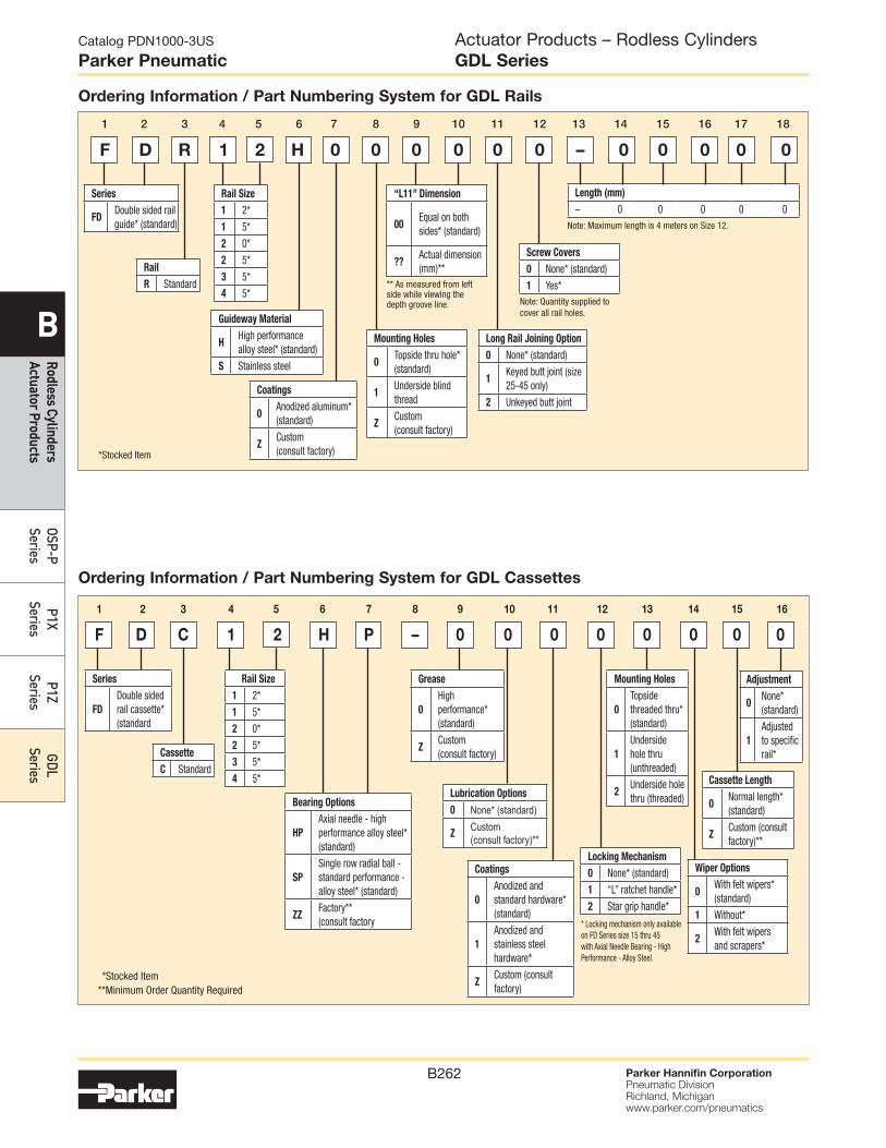
Parker Hannifin CorporationPneumatic DivisionRichland, Michiganwww.parker.com/pneumatics
B262
Catalog PDN1000-3US
Parker Pneumatic
B
Rodless Cylinders Actuator Products
OSP-P Series
P1X Series
P1Z Series
GDL Series
Ordering Information / Part Numbering System for GDL Rails
Length (mm)
– 0 0 0 0 0
Rail
R Standard
Rail Size
1 2*
1 5*
2 0*
2 5*
3 5*
4 5*
Series
FDDouble sided rail guide* (standard)
“L11” Dimension
00Equal on both sides* (standard)
??Actual dimension (mm)**
Guideway Material
HHigh performance alloy steel* (standard)
S Stainless steel
Coatings
0Anodized aluminum* (standard)
ZCustom (consult factory)
Mounting Holes
0Topside thru hole* (standard)
1Underside blind thread
ZCustom (consult factory)
Screw Covers
0 None* (standard)
1 Yes*
Long Rail Joining Option
0 None* (standard)
1Keyed butt joint (size 25-45 only)
2 Unkeyed butt joint
F D R 1 2 H 0 0 0 0 0 0 – 0 0 0 0 0
1 2 3 4 5 6 7 8 9 10 11 12 13 14 15 16 17 18
**Stocked Item**Minimum Order Quantity Required
*Stocked Item
Ordering Information / Part Numbering System for GDL Cassettes
Adjustment
0None* (standard)
1
Adjusted to specific rail*
Rail Size
1 2*
1 5*
2 0*
2 5*
3 5*
4 5*
Bearing Options
HP
Axial needle - high performance alloy steel* (standard)
SP
Single row radial ball - standard performance - alloy steel* (standard)
ZZFactory** (consult factory
Grease
0
High performance* (standard)
ZCustom (consult factory)
Mounting Holes
0
Topside threaded thru* (standard)
1
Underside hole thru (unthreaded)
2Underside hole thru (threaded)
Wiper Options
0With felt wipers* (standard)
1 Without*
2With felt wipers and scrapers*
Lubrication Options
0 None* (standard)
ZCustom (consult factory)**
Cassette Length
0Normal length* (standard)
ZCustom (consult factory)**
F D C 1 2 H P – 0 0 0 0 0 0 0 0
1 2 3 4 5 6 7 8 9 10 11 12 13 14 15 16
** As measured from left side while viewing the depth groove line. Note: Quantity supplied to
cover all rail holes.
Note: Maximum length is 4 meters on Size 12.
* Locking mechanism only available on FD Series size 15 thru 45 with Axial Needle Bearing - High Performance - Alloy Steel.
Coatings
0
Anodized and standard hardware* (standard)
1
Anodized and stainless steel hardware*
ZCustom (consult factory)
Series
FD
Double sided rail cassette* (standard
Cassette
C Standard
Locking Mechanism
0 None* (standard)
1 “L” ratchet handle*
2 Star grip handle*
Actuator Products – Rodless CylindersGDL Series