Embed Size (px)
DESCRIPTION
Ota000004 Sdh Principle Issue 2.0
Citation preview
Optical Network Curriculum Development Section
OTA000004 SDH PrincipleOTA000004 SDH Principle
Issue 2.0
ObjectivesObjectives
! Understand the basic of SDH multiplexing standard
! Know the features, applications and advantages of SDH based equipment
! Upon completion of this course, you will be able to:
Course ContentsCourse Contents
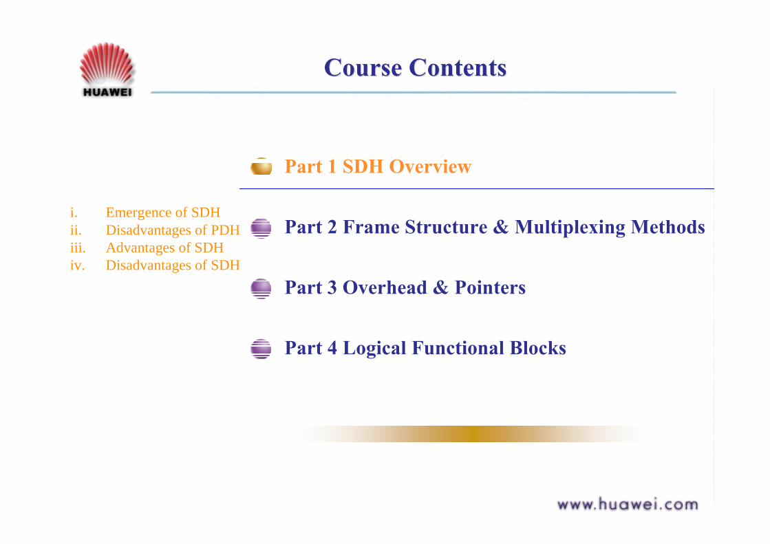
Part 1 SDH Overview
Part 2 Frame Structure & Multiplexing Methods
Part 3 Overhead & Pointers
Part 4 Logical Functional Blocks
i. Emergence of SDHii. Disadvantages of PDHiii. Advantages of SDHiv. Disadvantages of SDH
ReferencesReferences
! SDH Principle Manual
! ITU-T G.701, G.702, G.707
Emergence of SDHEmergence of SDH
What is SDH?
---- Synchronous Digital Hierarchy---- It defines frame structure, multiplexing method, digital rates hierarchy and interface code pattern.
Why did SDH emerge?
---- Need for a system to process increasing amounts of information.---- New standard that allows mixing equipment from different suppliers.
BACK

Disadvantages of PDHDisadvantages of PDH
1. InterfacesElectrical interfaces--- Only regional standards. 3 PDH rate hierarchies for PDH: European (2.048 Mb/s), Japanese, North American (1.544 Mb/s).Optical interfaces--- No standards for optical line equipment, manufacturers develop at their will.
Plesiochronous Digital Hierarchy
Disadvantages of PDHDisadvantages of PDH
2. Multiplexing methods
Asynchronous Multiplexing for PDH
The location of low-rate signals in high-rate signals is not regular nor predictable.
Disadvantages of PDHDisadvantages of PDH
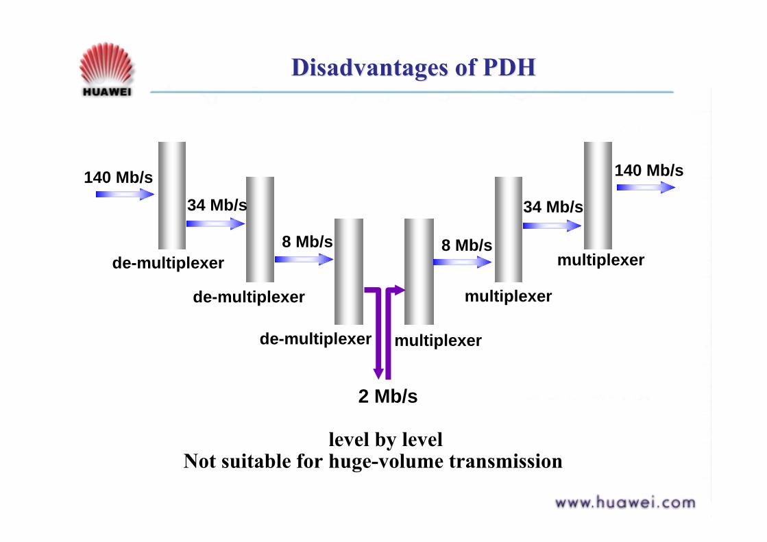
140 Mb/s34 Mb/s 34 Mb/s
8 Mb/s 8 Mb/s
2 Mb/s
140 Mb/s
de-multiplexer
de-multiplexer
de-multiplexer multiplexer
multiplexer
multiplexer
level by levelNot suitable for huge-volume transmission
Disadvantages of PDHDisadvantages of PDH
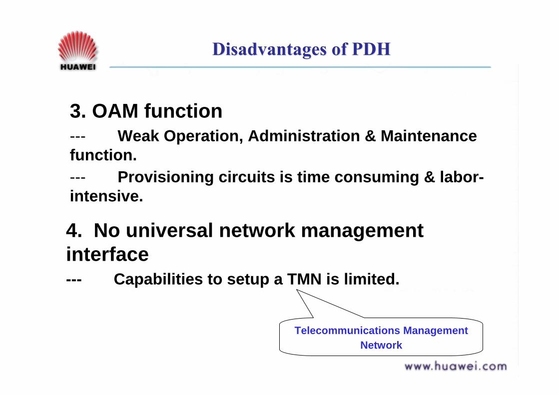
3. OAM function--- Weak Operation, Administration & Maintenance function.--- Provisioning circuits is time consuming & labor-intensive.
4. No universal network management interface--- Capabilities to setup a TMN is limited.
Telecommunications Management Network

Advantages of SDHAdvantages of SDH
1. Interfaces
Electrical interfaces--- Can be connected to all existing PDH signals.Optical interfaces--- Can be connected to multiple vendors’optical transmission equipment.
BACK
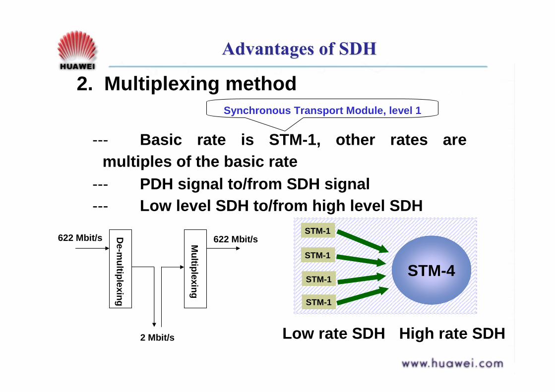
Advantages of SDHAdvantages of SDH
--- Basic rate is STM-1, other rates are multiples of the basic rate
--- PDH signal to/from SDH signal--- Low level SDH to/from high level SDH
Synchronous Transport Module, level 1
2. Multiplexing method
STM-1
STM-1
STM-1
STM-4STM-1
Low rate SDH High rate SDH
622 Mbit/s 622 Mbit/s
2 Mbit/s
De-m
ultiplexing
Multiplexing
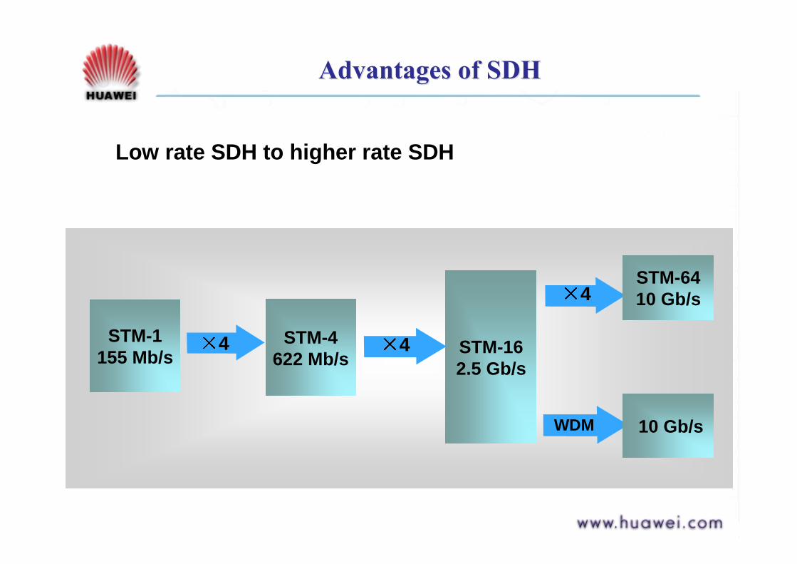
Advantages of SDHAdvantages of SDH
4
WDM
STM-1 155 Mb/s
STM-4 622 Mb/s STM-16
2.5 Gb/s 4
4STM-64 10 Gb/s
10 Gb/s
Low rate SDH to higher rate SDH
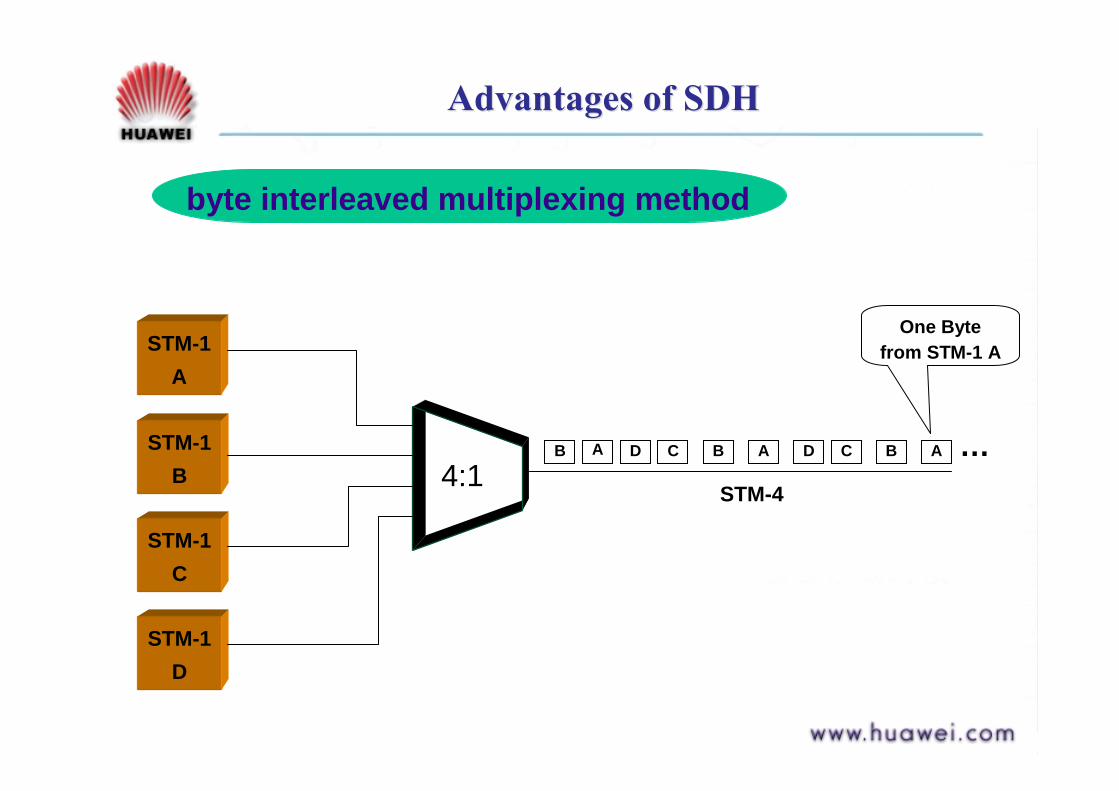
Advantages of SDHAdvantages of SDH
byte interleaved multiplexing method
4:1
STM-1A
STM-1B
STM-1C
STM-1D
B ACDABCDAB …STM-4
One Byte from STM-1 A

Advantages of SDHAdvantages of SDHOptical Interface only scrambles the electrical
signal
The optical code pattern SDH uses is Scrambled NRZ
PDH uses mBnB
Synchronous multiplexing method and flexible mapping structure
Use multistage pointer to align PDH loads in SDH frame, thus, dynamic drop-and-insert capabilities
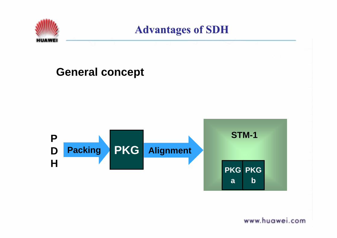
Advantages of SDHAdvantages of SDH
General concept
Packing PKG Alignment
PKGa
PKGb
STM-1PDH

Advantages of SDHAdvantages of SDH
3. OAM function--- Abundant overheads bytes for automation,
network monitoring and maintenance--- About 5% of the total bytes are being used
Advantages of SDHAdvantages of SDH
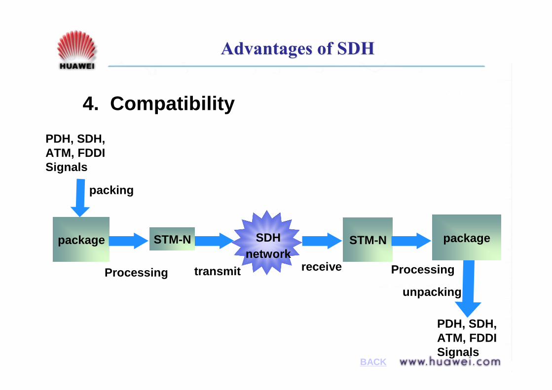
4. Compatibility
package
packing
Processing transmit
SDHnetwork
unpacking
PDH, SDH, ATM, FDDI Signals
receive Processing
STM-N STM-N package
PDH, SDH, ATM, FDDI Signals
BACK
Disadvantages of SDHDisadvantages of SDH
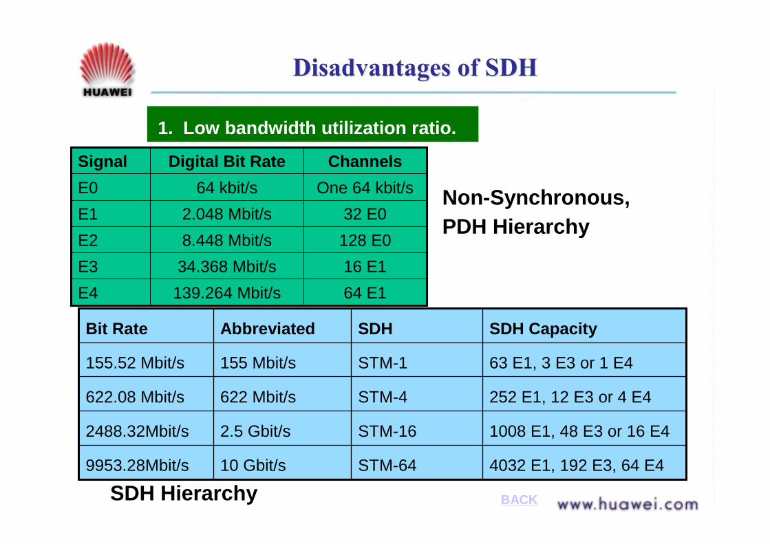
1. Low bandwidth utilization ratio.
64 E1139.264 Mbit/sE416 E134.368 Mbit/sE3128 E08.448 Mbit/sE232 E02.048 Mbit/sE1
One 64 kbit/s64 kbit/sE0ChannelsDigital Bit RateSignal
4032 E1, 192 E3, 64 E4STM-6410 Gbit/s9953.28Mbit/s
1008 E1, 48 E3 or 16 E4STM-162.5 Gbit/s2488.32Mbit/s
252 E1, 12 E3 or 4 E4STM-4622 Mbit/s622.08 Mbit/s
63 E1, 3 E3 or 1 E4STM-1155 Mbit/s155.52 Mbit/s
SDH CapacitySDHAbbreviatedBit Rate
Non-Synchronous, PDH Hierarchy
SDH Hierarchy BACK

Disadvantages of SDHDisadvantages of SDH
2. Mechanism of pointer adjustment is complex.
3. Large-scale application of software makes SDH system vulnerable to viruses or malpractice.
QuestionsQuestions
1. Why did SDH emerge?
2. What are the advantages & disadvantages of SDH?
3. What is the basic transmission rate in SDH and what are the other common ones?
Time to think
Soon Coffee Time!
AnswersAnswers
1. Click to SDH Emergence
2. Click to Advantages and Disadvantages of SDH
3. STM-1. STM-4, STM-16, STM-64
i. Frame Structure of STM-Nii. Functions of each partsiii. SDH tributary multiplexing
Course ContentsCourse Contents
Part 1 SDH Overview
Part 2 Frame structure & Multiplexing Methods
Part 3 Overheads & Pointers
Part 4 Logical functional Blocks

Part 2 SDH Frame Structure Part 2 SDH Frame Structure
From ITU-T G.707:
1. STM-1 is the basic transmission format
2. One frame lasts for 125 microseconds (8000 frames/s
3. Rectangular block structure 9 rows and 270 columns
4. Each unit is one byte (8 bits)5. Transmission mode: Byte
by byte, row by row, from left to right, from top to bottom
Frame = 125 us
1 byte = One 64 kbit/s channelSTM-N = 9 X 270 X N (N = 4, 16, 64)
123456789
270 Columns
9 rows

SDH Frame StructureSDH Frame Structure
Three parts:1. Information
Payload2. Section
Overhead3. Pointer
Frame = 125 us
9
SOH
PTR Information Payload
SOH123456789
270 Columns
9 rows
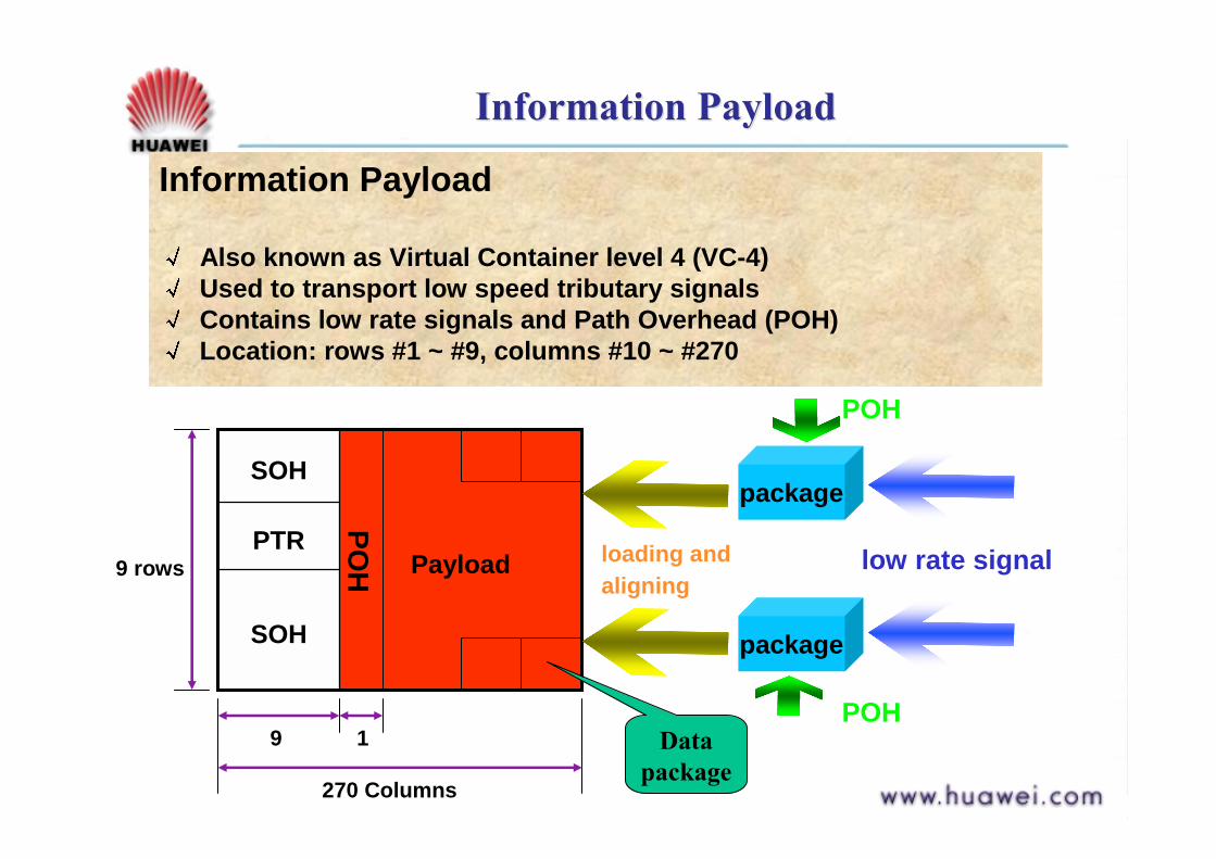
Information PayloadInformation Payload
Information Payload
Also known as Virtual Container level 4 (VC-4)Used to transport low speed tributary signalsContains low rate signals and Path Overhead (POH)Location: rows #1 ~ #9, columns #10 ~ #270
9
SOH
PTRPayload
SOH
270 Columns
POH
1
package
package
low rate signal
POH
POH
9 rows loading andaligning
Data package

SDH OverheadSDH Overhead
one Path ( low rate signal)one Path ( low rate signal)
one Path ( low rate signal)
Section(SDH signal)
Two main types of overheads:1. Section Overhead2. Path Overhead
Concept of Path and Section

Section OverheadSection Overhead
Fulfills the section layer OAM functions
9
MSOH
PTR Information Payload
RSOH
270 Columns
9 rows
Types of Section Overhead
1. Regenerator Section Overhead (RSOH), monitors the whole STM-N
2. Multiplex Section Overhead (MSOH), monitors STM-1 in STM-NLocation:
1. RSOH: rows #1 ~ #3, columns #1 ~ #9
2. MSOH: rows #5 ~ #9, columns #1 ~ #9
123
56789
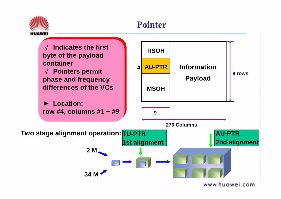
PointerPointer
9
MSOH
AU-PTR Information Payload
RSOH
270 Columns
9 rows4
Indicates the first byte of the payload container
Pointers permit phase and frequency differences of the VCs
► Location: row #4, columns #1 ~ #9
2 M
34 M
TU-PTR1st alignment
AU-PTR2nd alignment
Two stage alignment operation:
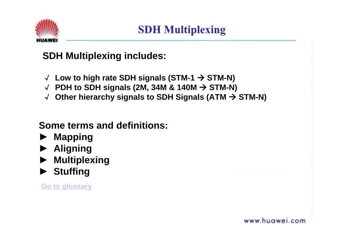
SDH MultiplexingSDH Multiplexing
SDH Multiplexing includes:
Low to high rate SDH signals (STM-1 """" STM-N)PDH to SDH signals (2M, 34M & 140M """" STM-N)Other hierarchy signals to SDH Signals (ATM """" STM-N)
Some terms and definitions:► Mapping► Aligning► Multiplexing► StuffingGo to glossary
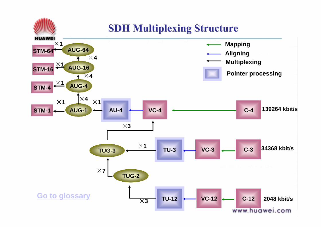
SDH Multiplexing StructureSDH Multiplexing Structure
STM-1 AU-4
TU-3
AUG-1
TUG-3 VC-3 C-3
VC-4 C-4
TU-12 VC-12 C-12
TUG-2
1 1
3
1
7
3
139264 kbit/s
34368 kbit/s
2048 kbit/s
Pointer processing
Multiplexing
MappingAligning
AUG-4
AUG-16
AUG-64
STM-4
STM-16
STM-64
1
1
1
4
4
4
Go to glossary

SDH Tributary Multiplexing (140M)SDH Tributary Multiplexing (140M)
140 Mbit/s to STM-N
140M Rate adaptation
Add POH
1C4
1 2609
125 s
1 1
9
VC4
POH
125 s1 261
Next page
Packing Mapping

SDH Tributary Multiplexing (140M)SDH Tributary Multiplexing (140M)
AddPointer AU-PTR
AU-4
1 9
10 270
AddSOH
1 270
RSOH
MSOH
InfoPayload
AU-PTR
1
9Aligning
STM-1
1
AUG-1
MultiplexingAUG-N 1 270X N
1
9
STM-N
Multiplexing
Multiplexing route: 1X140M """" 1XVC-4 """"1XSTM-1One STM-1 frame can load only one 140Mbit/s Signal

SDH Tributary Multiplexing (34M)SDH Tributary Multiplexing (34M)
34 Mbit/s to STM-N
34M Rate Adaptation
Add POH
1
C3
1 849
125 s
1 1
9
VC3
POH
125 s1 85
Next page
Packing Mapping
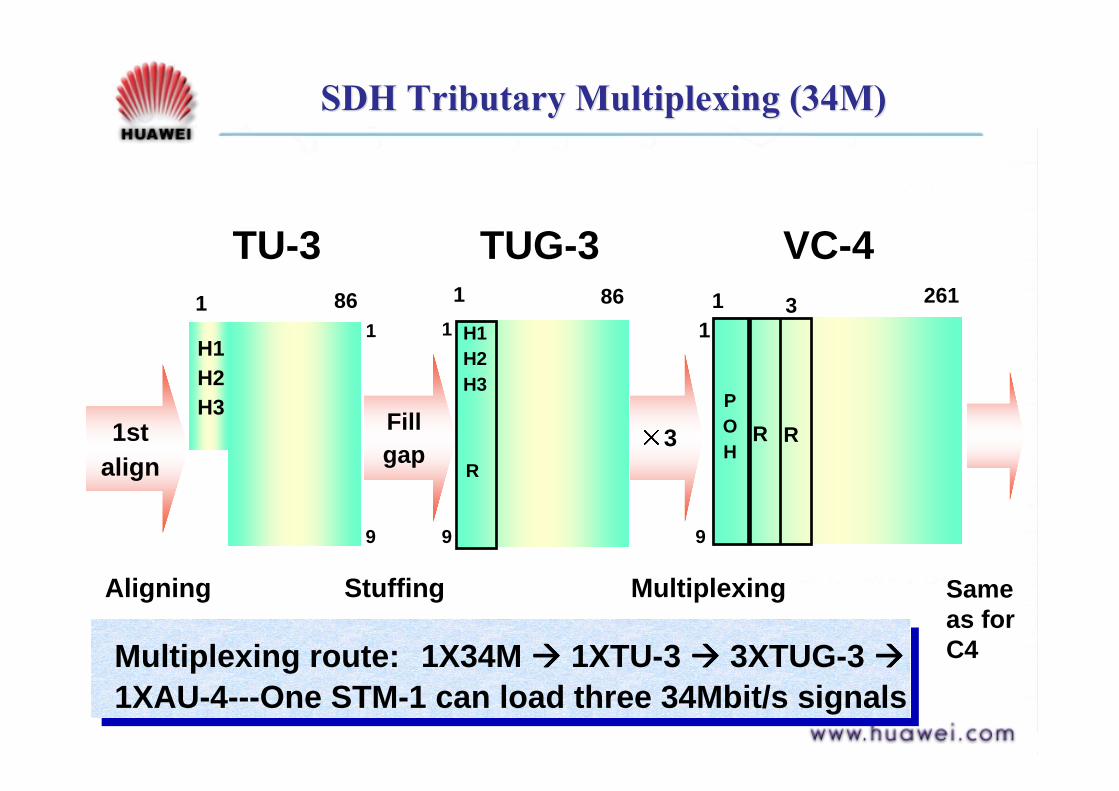
SDH Tributary Multiplexing (34M)SDH Tributary Multiplexing (34M)
1st align
Fillgap
1 861
9
H1H2H3
R3
86
TU-31
H1H2H3
1
9
POH
R R
VC-4
9
11 261
Aligning Stuffing
TUG-3
Multiplexing
3
Same as for C4Multiplexing route: 1X34M """" 1XTU-3 """" 3XTUG-3 """"
1XAU-4---One STM-1 can load three 34Mbit/s signals
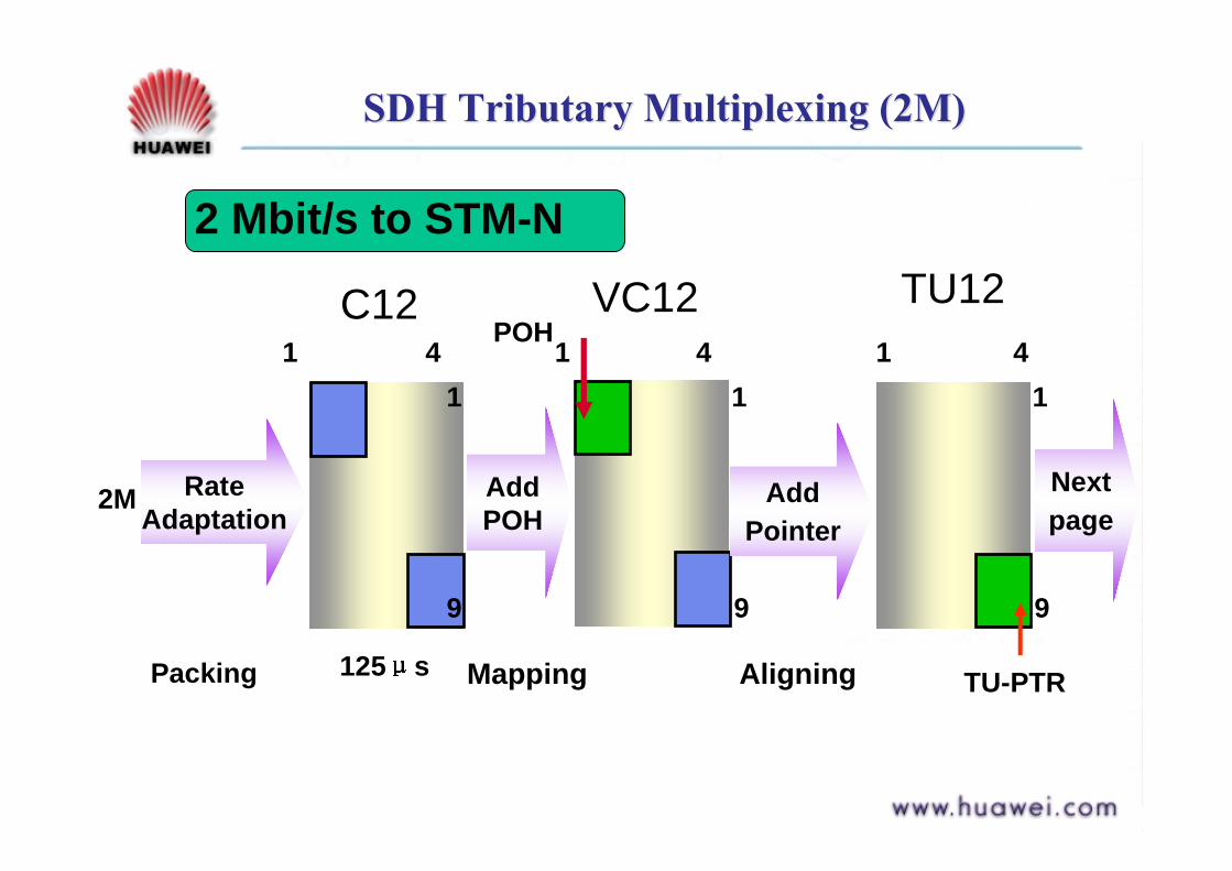
SDH Tributary Multiplexing (2M)SDH Tributary Multiplexing (2M)
2 Mbit/s to STM-N
2M Nextpage
125 s
POH1 4
C12
1
9
VC121 4
1
9
TU121 4
1
9
TU-PTR
Rate Adaptation
Add POH
Packing
Add Pointer
Mapping Aligning
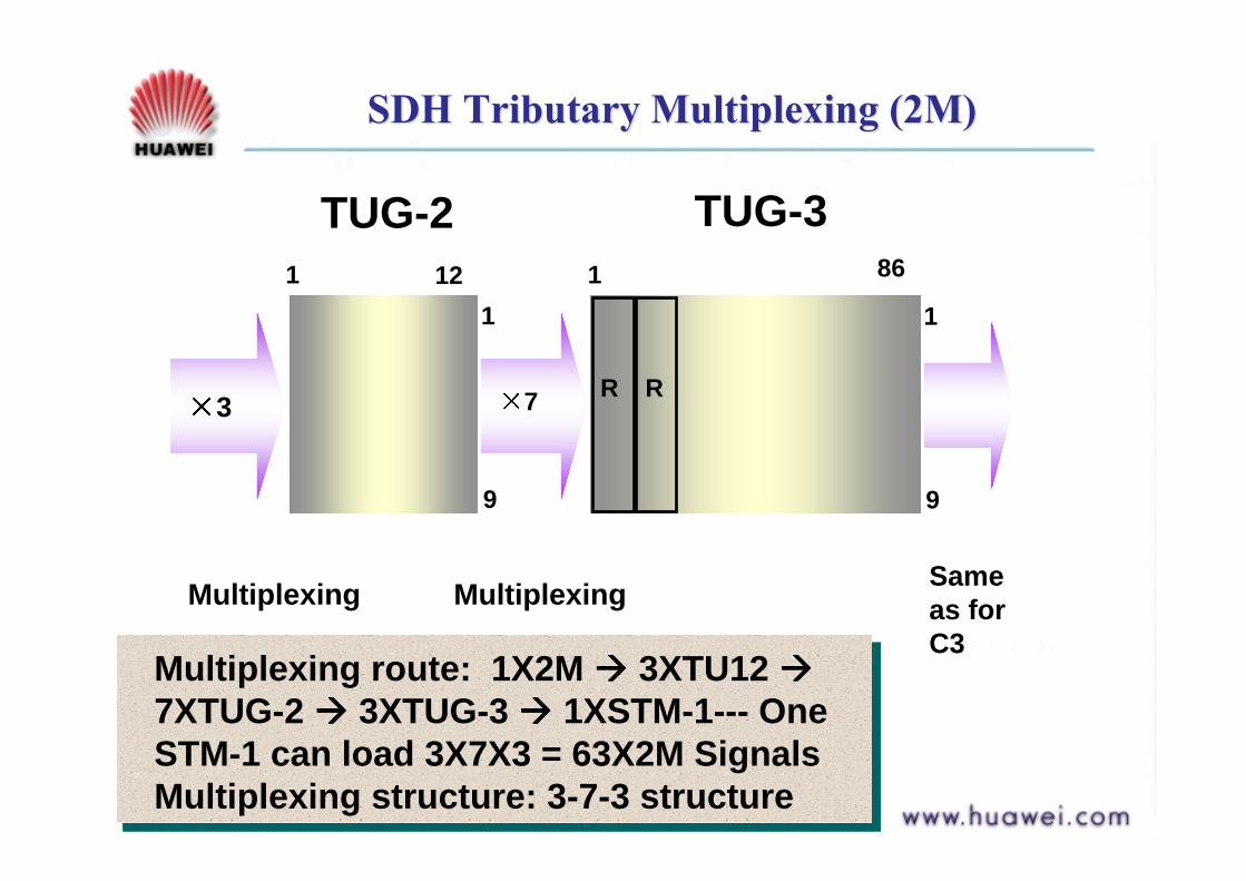
SDH Tributary Multiplexing (2M)SDH Tributary Multiplexing (2M)
3
1 12
TUG-2
1
9
7 R R
TUG-31 86
Multiplexing
1
9
Multiplexing Same as for C3
Multiplexing route: 1X2M """" 3XTU12 """"7XTUG-2 """" 3XTUG-3 """" 1XSTM-1--- One STM-1 can load 3X7X3 = 63X2M SignalsMultiplexing structure: 3-7-3 structure

QuestionsQuestions
1. What are the main parts of the SDH Frame structure?
2. What is the transmission speed of STM-1? Why is that so?
3. Why is multiframe used for the 2Mbit/s signal?

AnswersAnswers
1. Three main parts: a. Information Payload b. SOH c. PTR
2. Transmission speed = 155.52 Mbit/s, 270X9X8000X8
3.
GlossaryGlossary
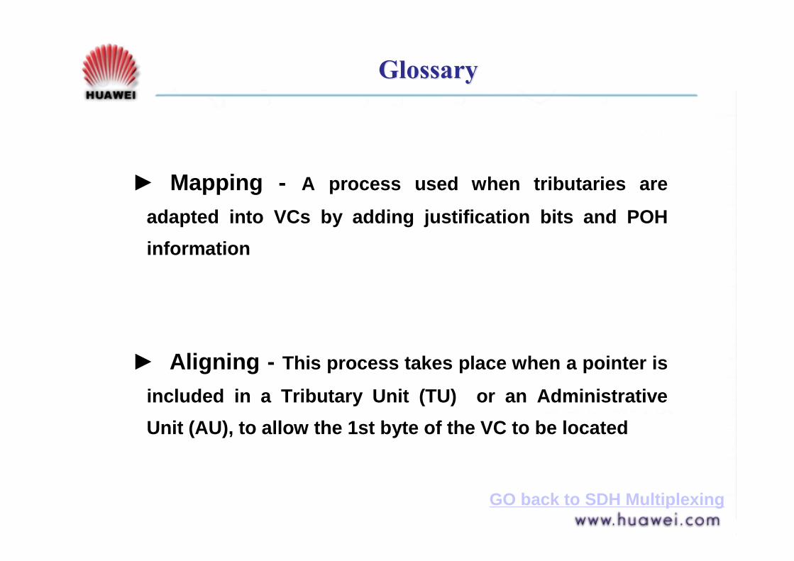
► Mapping - A process used when tributaries are adapted into VCs by adding justification bits and POH information
► Aligning - This process takes place when a pointer is included in a Tributary Unit (TU) or an Administrative Unit (AU), to allow the 1st byte of the VC to be located
GO back to SDH Multiplexing
GlossaryGlossary
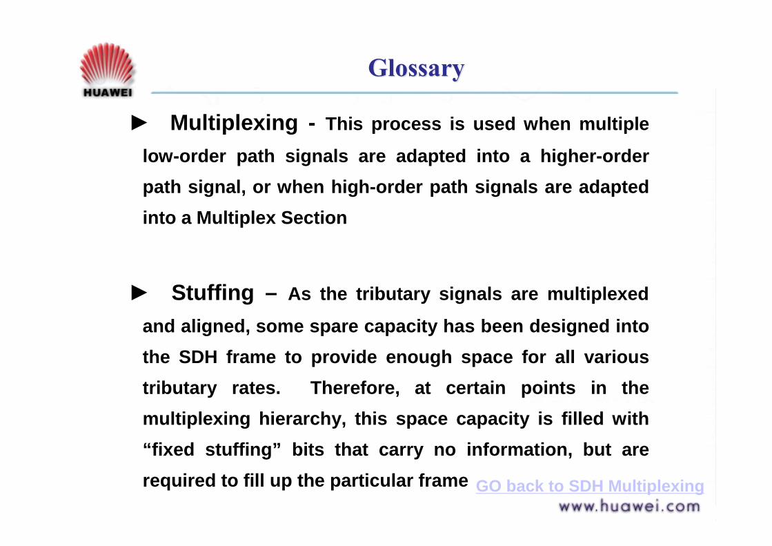
► Multiplexing - This process is used when multiple low-order path signals are adapted into a higher-order path signal, or when high-order path signals are adapted into a Multiplex Section
► Stuffing – As the tributary signals are multiplexed and aligned, some spare capacity has been designed into the SDH frame to provide enough space for all various tributary rates. Therefore, at certain points in the multiplexing hierarchy, this space capacity is filled with “fixed stuffing” bits that carry no information, but are required to fill up the particular frame GO back to SDH Multiplexing

GlossaryGlossary
! SDH Multiplexing Structure
C = Container
VC = Virtual Container
TU = Tributary Unit
AU = Administrative Unit
TUG = Tributary Unit Group
AUG = Administrative Unit Group
STM = Synchronous Transfer Module
Go back

GlossaryGlossary
! TU Multiframe
In the floating TU mode, four consecutive 125 microsecond framesof the VC-4 are combined into one 500 microsecond structure, called a TU Multiframe. The occurrence or the TU Multiframe andits phase is indicated in the VC-N Path Overhead.
! Concatenation
The linking together of various data structures. In SDH, a number (M) of TUs can be linked together to produce a concatenated container, M times the size of the TU.
Course ContentsCourse Contents
Part 1 SDH Overview
Part 2 Frame structure & Multiplexing Methods
Part 3 Overheads & Pointers
Part 4 Logical functional Blocksi. SOH
a. RSOHb. MSOH
ii. POHa. H.O. POHb. L.O. POH
iii. POINTERSa. AU-PTRb. TU-PTR
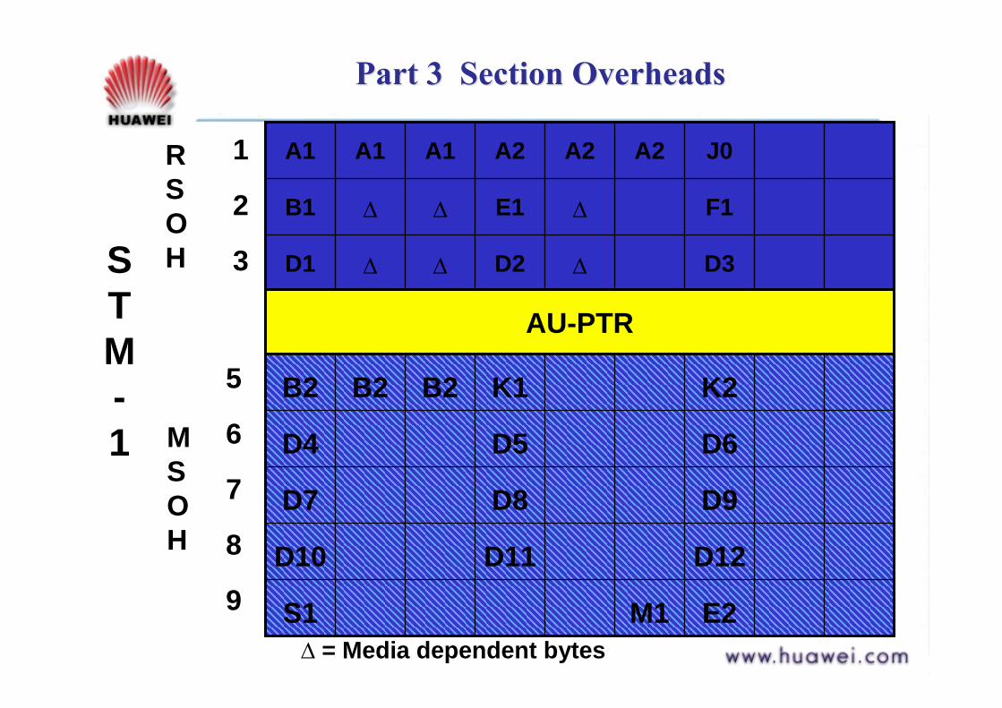
Part 3 Section Overheads Part 3 Section Overheads
D3∆D2∆∆D1
F1∆E1∆∆B1
J0A2A2A2A1A1A11
2
3
AU-PTR
E2M1S1
D12D11D10
D9D8D7
D6D5D4
K2K1B2B2B25
6
7
8
9
STM-1
RSOH
MSOH
∆ = Media dependent bytes

A1 and A2 BytesA1 and A2 Bytes
# Framing Bytes – Indicate the beginning of the STM-N frame
# The A1, A2 bytes are unscrambled# A1 = f6H (11110110), A2 = 28H (00101000)# In STM-N: (3XN) A1 bytes, (3XN) A2 bytes
stream
STM-N STM-N STM-N STM-N STM-N STM-N
Finding frame head
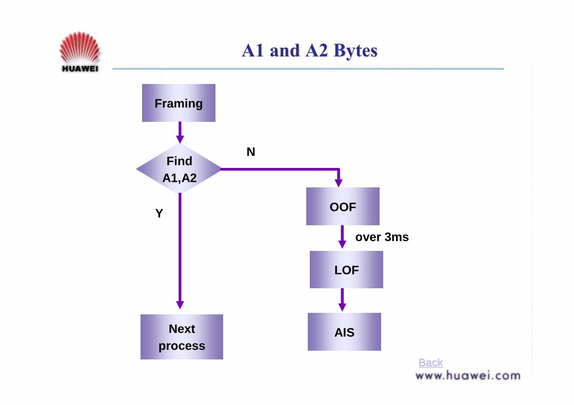
A1 and A2 BytesA1 and A2 Bytes
Framing
Nextprocess
FindA1,A2
OOF
LOF
N
Y
AIS
over 3ms
BackBack

D1 ~ D12 BytesD1 ~ D12 Bytes
Data Communications Channels (DCC) Bytes –# Message-based Channel for OAM between NEsand NMS# RS-DCC – D1 ~ D3 – 192 kbit/s (3X64 kbit/s)# MS-DCC – D4 ~ D12 – 576 kbit/s (9X64kbit/s)
TMNDCC channel
NE NE NENE
OAM Information: Control, Maintenance, Remote Provisioning, Monitoring (Alarm & Performance), Administration

E1 and E2 BytesE1 and E2 Bytes
Digital telephone channelE1-RS, E2-MS
E1 and E2
NE NE NENE
# Orderwire Bytes – Provides one 64 kbit/s each for voice communication# E1 – RS Orderwire Byte – RSOH orderwire message# E2 – MS Orderwire Byte – MSOH orderwire message

B1 ByteB1 Byte
Bit interleaved Parity Code (BIP-8) Byte –# A parity code (even parity), used to check the transmission errors over the RS# B1 BBE is represented by RS-BBE
Tx
2#STM-N
Rx
1#STM-NCalculateB1, B2
1#STM-N
2#STM-N
Verify B1 B2
STM-NA1 00110011A2 11001100A3 10101010A4 00001111
B 01011010
BIP-8
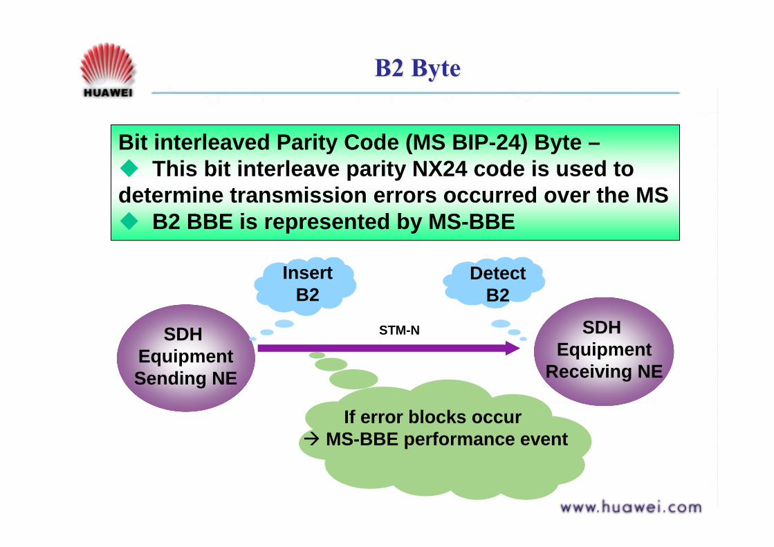
B2 ByteB2 Byte
Bit interleaved Parity Code (MS BIP-24) Byte –# This bit interleave parity NX24 code is used to determine transmission errors occurred over the MS# B2 BBE is represented by MS-BBE
If error blocks occur " MS-BBE performance event
SDH Equipment
Receiving NE
SDH EquipmentSending NE
Detect B2
Insert B2
STM-N

M1 ByteM1 Byte
Tx Rx
Traffic
Return M1GenerateMS-REI
Find MS-BBE
Multiplex Section Remote Error Indication MS-REIByte
# A return message from Rx to Tx ,when Rx find MS-BBE
# A count of the number of BIP-24xN (B2) errors# Tx generate corresponding performance event MS-
REI
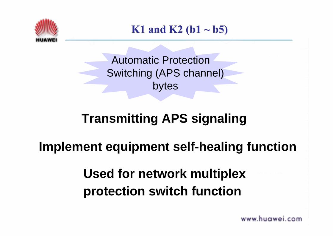
K1 and K2 (b1 ~ b5)K1 and K2 (b1 ~ b5)
Automatic Protection Switching (APS channel)
bytes
Transmitting APS signaling
Implement equipment self-healing function
Used for network multiplex protection switch function
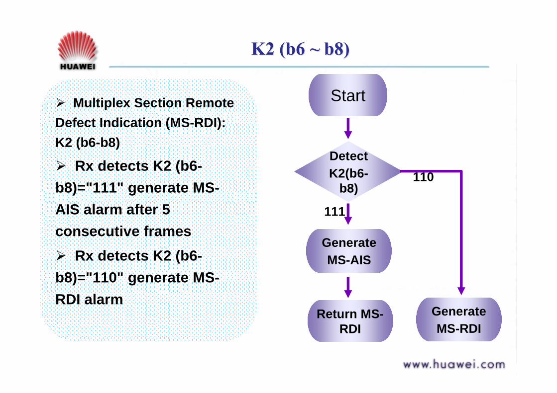
K2 (b6 ~ b8)K2 (b6 ~ b8)
$ Multiplex Section Remote Defect Indication (MS-RDI): K2 (b6-b8)
$ Rx detects K2 (b6-b8)="111" generate MS-AIS alarm after 5 consecutive frames$ Rx detects K2 (b6-b8)="110" generate MS-RDI alarm
GenerateMS-AIS
Start
DetectK2(b6-
b8)
Return MS-RDI
111
GenerateMS-RDI
110

S1 ByteS1 Byte
Synchronization Status Message Byte (SSMB): S1 Synchronization Status Message Byte (SSMB): S1 (b5~ b8)(b5~ b8)
$$ Value indicates the sync. levelValue indicates the sync. level$$ Used to implement the clock source protection Used to implement the clock source protection
functionfunction
G.813 (Sync. Equipment Timing Clock)G.813 (Sync. Equipment Timing Clock)1011
Do not use for sync.Do not use for sync.1111
SSUSSU--B (G.812 local)B (G.812 local)1000
SSUSSU--A (G.812 transit)A (G.812 transit)0100
G.811 PRCG.811 PRC0010
Quality unknown (existing sync. Network)Quality unknown (existing sync. Network)0000
Meaningbits 5 ~ 8

Path OverheadsPath Overheads
N1
K3
F3
H4
F2
G1
C2
B3
J1123456789
VC-n Path Trace BytePath BIP-8Path Signal LabelPath Status
Path User ChannelTU Multiframe IndiPath User ChannelAP Switching
Network Operator
Higher Order Path OverheadHigher Order Path Overhead
1 2 3 4 5 6 7 8 9 10
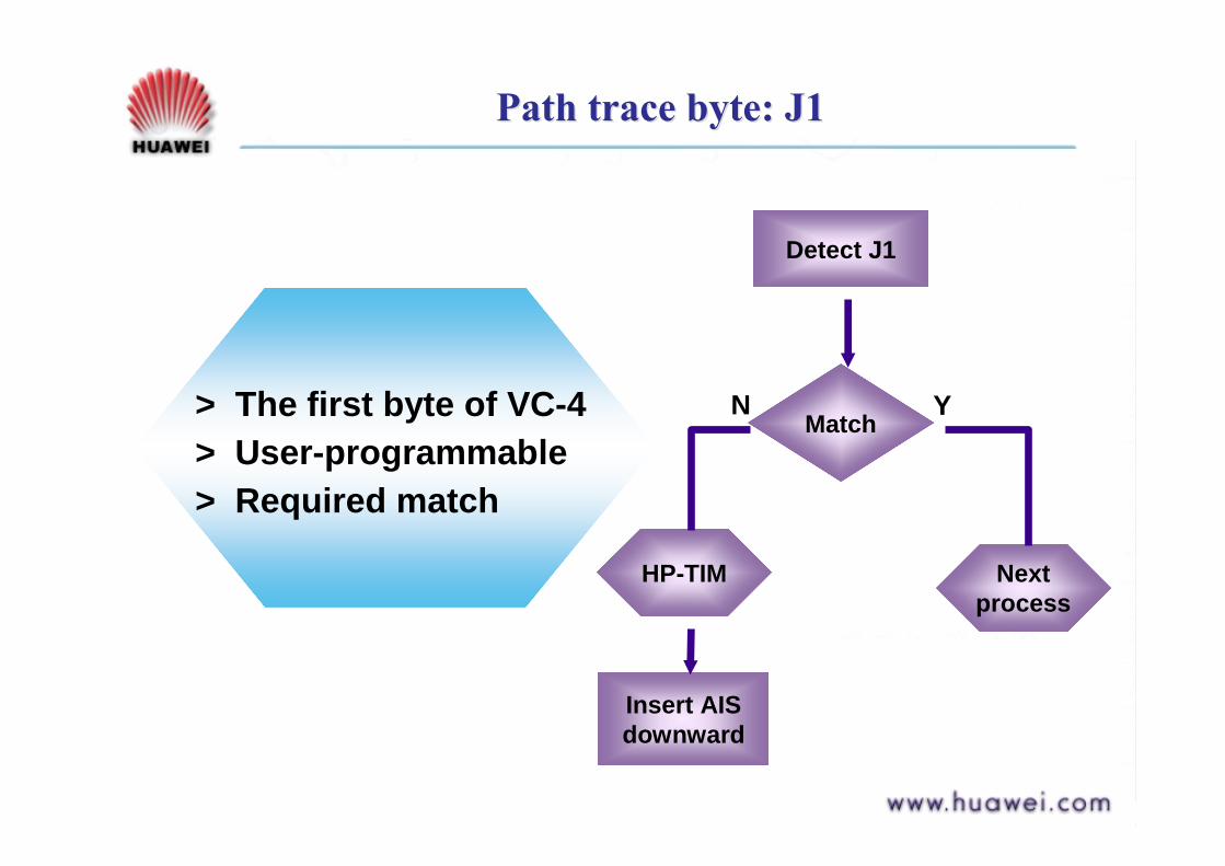
Path trace byte: J1Path trace byte: J1
Next process
Detect J1
Match
HP-TIM
Insert AIS downward
YN> The first byte of VC-4> User-programmable> Required match

Path BIP-8 BytePath BIP-8 Byte
Next process
Verify B3
correct
HP-BBE
YN
> Path bit interleaved paritycode byte (even parity code)
> Used to detecttransmission errors(Performance Monitoring)
> Calculated over all bitsof the previous VC beforescrambling and placed inthe B3 of the current frame

Signal label byte: C2Signal label byte: C2
> Specifies the mapping type in the VC-N
> 00 H " Unequipped02 H " TUG structure13 H " ATM mapping
> Requires matching
Detect C2
00H
HP-UNEQMatch
HP-SLMNext process
Insert AIS downward
N Y
NY

Path Status Byte: G1Path Status Byte: G1
Detect receiving VC4
HP-UNEQHP-TIMHP-SLM
Return HP-RDI
HP-BBE
ReturnHP-REI
Next process
N Y
N Y
> Return performance message from Rx to Tx
> HP-REI " b1 ~ b4
> HP-RDI " b5

Path OverheadsPath Overheads
VC-12VC-12VC-12VC-12
K4N2J2V51
9
1 4
500 s VC-12 multiframe
Low Order Path OverheadLow Order Path Overhead

Path Overhead BytesPath Overhead Bytes
V5V5> First byte of the > First byte of the multiframemultiframe> Indicated by TU> Indicated by TU--PTRPTR> Functions: Error checking, Signal Label and Path Status > Functions: Error checking, Signal Label and Path Status of VCof VC--1212
!! b1 ~ b2b1 ~ b2 "" Error Performance Monitoring (BIPError Performance Monitoring (BIP--2)2)!! b3b3 "" Return Error detected in VCReturn Error detected in VC--12 (LP12 (LP--REI)REI)!! b4b4 "" Return Failure declared in VCReturn Failure declared in VC--12 (LP12 (LP--RFI)RFI)!! b5 ~ b7b5 ~ b7 "" Signal Label for VCSignal Label for VC--1212!! b8b8 "" Indicate Defect in VCIndicate Defect in VC--12 path (LP12 path (LP--RDI)RDI)
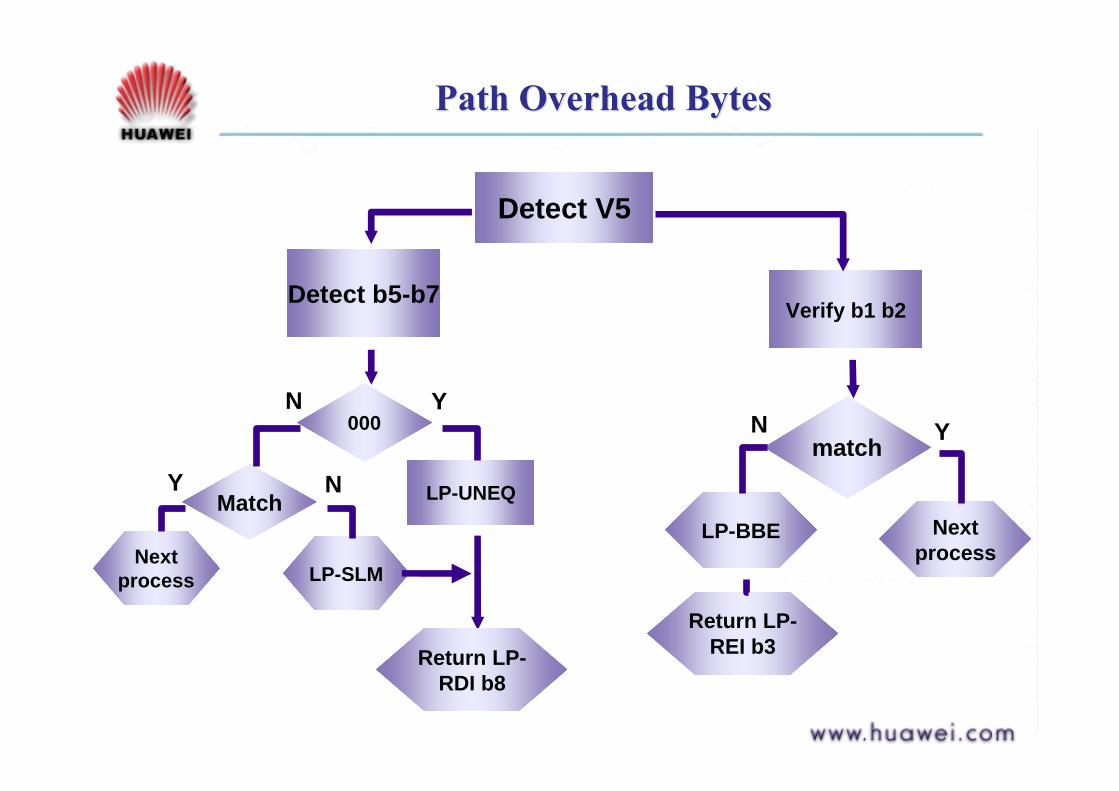
Path Overhead BytesPath Overhead Bytes
Next process
Verify b1 b2
match
LP-BBE
YN
Detect V5
Return LP-REI b3
Detect b5-b7
000
LP-UNEQMatch
LP-SLMNext
process
N Y
NY
Return LP-RDI b8
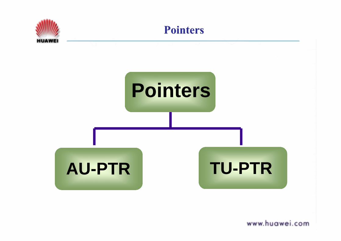
PointersPointers
Pointers
AU-PTR TU-PTR
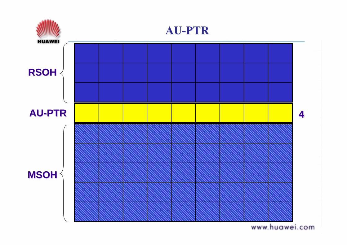
AU-PTRAU-PTR
RSOHRSOH
AUAU--PTRPTR
MSOHMSOH
44

AU-PTRAU-PTR
> Payload pointers to permit differences in > Payload pointers to permit differences in phase and frequency of the VCphase and frequency of the VC--N wrt the STMN wrt the STM--NN> Indicates the offset between VC payload & > Indicates the offset between VC payload & STMSTM--N frame by pointing to the 1st byte in the N frame by pointing to the 1st byte in the VCVC> Consists of H1, H2 and H3 Bytes> Consists of H1, H2 and H3 Bytes> Divide the VC> Divide the VC--4 payload bytes into 3 4 payload bytes into 3 "" 783 783 unitsunits> Each unit is given an address > Each unit is given an address "" 0 ~ 7820 ~ 782
H3H3H311H2YYH1
3 x AU3 x AU--33
1 x AU1 x AU--441 = All 1s1 = All 1sY = 1001ss11Y = 1001ss11(S bits unspecified)(S bits unspecified)
H3H3H3H2H2H2H1H1H1
AU-PTRAU-PTR
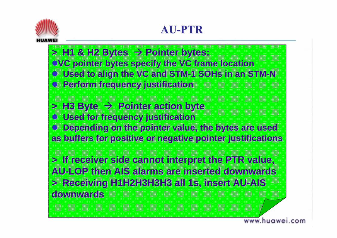
> H1 & H2 Bytes > H1 & H2 Bytes "" Pointer bytes:Pointer bytes:!!VC pointer bytes specify the VC frame locationVC pointer bytes specify the VC frame location!! Used to align the VC and STMUsed to align the VC and STM--1 SOHs in an STM1 SOHs in an STM--NN!! Perform frequency justificationPerform frequency justification
> H3 Byte > H3 Byte "" Pointer action bytePointer action byte!! Used for frequency justificationUsed for frequency justification!! Depending on the pointer value, the bytes are used Depending on the pointer value, the bytes are used as buffers for positive or negative pointer justificationsas buffers for positive or negative pointer justifications
> If receiver side cannot interpret the PTR value, > If receiver side cannot interpret the PTR value, AUAU--LOP then AIS alarms are inserted downwardsLOP then AIS alarms are inserted downwards> Receiving H1H2H3H3H3 all 1s, insert AU> Receiving H1H2H3H3H3 all 1s, insert AU--AIS AIS downwardsdownwards

TU-PTRTU-PTR
V4V3V2V1
VC-12VC-12VC-12VC-12
1
9
500 s VC-12 multiframe
TU POINTERSTU POINTERS
11 44
TU-PTRTU-PTR
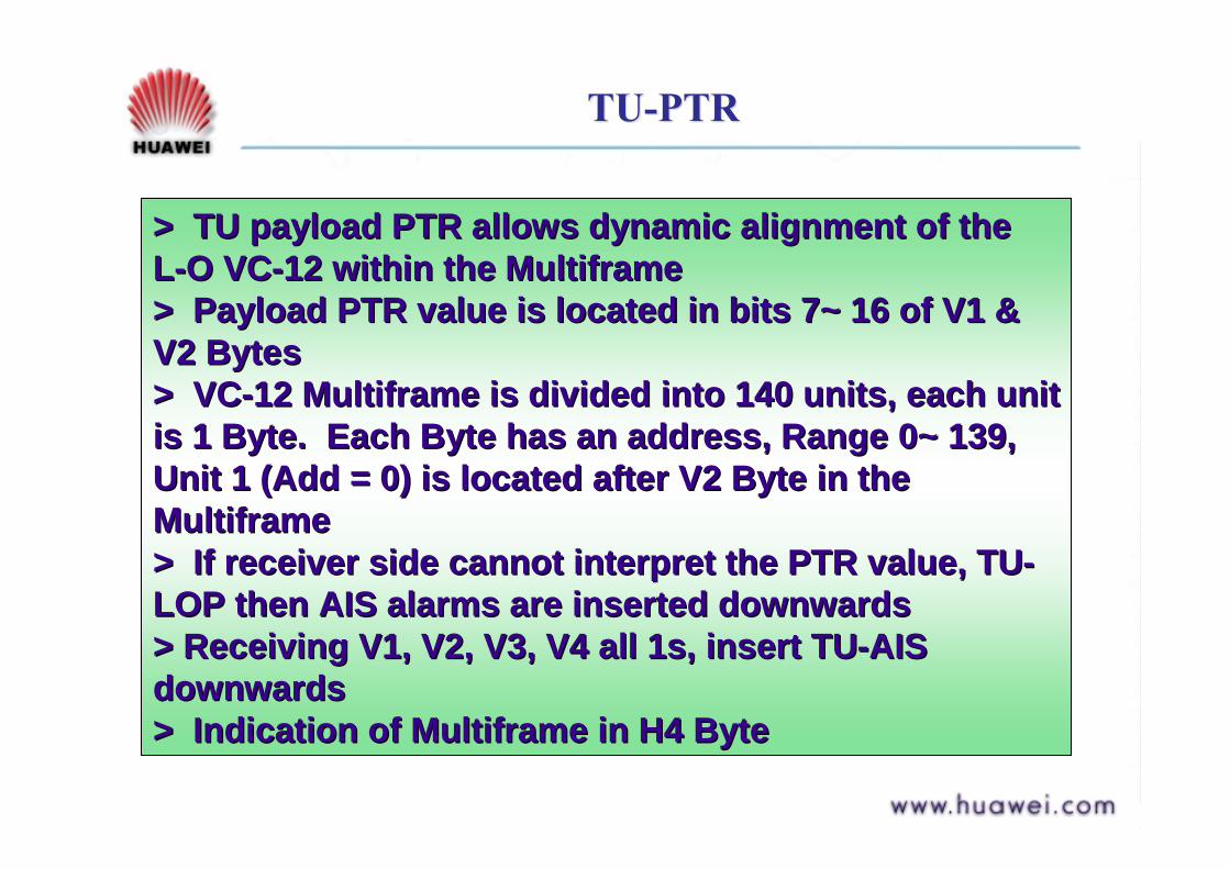
> TU payload PTR allows dynamic alignment of the > TU payload PTR allows dynamic alignment of the LL--O VCO VC--12 within the 12 within the MultiframeMultiframe> Payload PTR value is located in bits 7~ 16 of V1 & > Payload PTR value is located in bits 7~ 16 of V1 & V2 BytesV2 Bytes> VC> VC--12 12 MultiframeMultiframe is divided into 140 units, each unit is divided into 140 units, each unit is 1 Byte. Each Byte has an address, Range 0~ 139, is 1 Byte. Each Byte has an address, Range 0~ 139, Unit 1 (Add = 0) is located after V2 Byte in the Unit 1 (Add = 0) is located after V2 Byte in the MultiframeMultiframe> If receiver side cannot interpret the PTR value, TU> If receiver side cannot interpret the PTR value, TU--LOP then AIS alarms are inserted downwardsLOP then AIS alarms are inserted downwards> Receiving V1, V2, V3, V4 all 1s, insert TU> Receiving V1, V2, V3, V4 all 1s, insert TU--AIS AIS downwardsdownwards> Indication of > Indication of MultiframeMultiframe in H4 Bytein H4 Byte
QuestionsQuestions! Which bytes in the Overhead are not scrambled for
transmission?
! Which byte is used to monitor the MS-AIS and MS-RDI?
! What is the mechanism for R-LOF generation?
! What are the alarms generated when the receiver have detected that the AU-PTR is 800 or 1023?
! Which bytes implement the layered error monitoring?
AnswersAnswers! A1, A2 & J0
! K2
! See Framing Bytes (Go To)
! After 8 consecutive frames AU-LOP then AU-AIS will be generated
! B1, B2 and B3

SummarySummary
! SOH consists of RSOH & MSOH
! POH consists of L-O POH & H-O POH
! PTR consists of AU-PTR & TU-PTR

Course ContentsCourse Contents
Part 1 SDH Overview
Part 2 Frame structure & Multiplexing Methods
Part 3 Overheads & Pointers
Part 4 Composition of SDH Equipment
i. SDH Network Elementsii. SDH Logical Functional Blocks
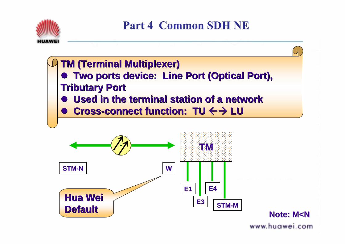
Part 4 Common SDH NE Part 4 Common SDH NE
TM (Terminal Multiplexer)TM (Terminal Multiplexer)!! Two ports device: Line Port (Optical Port), Two ports device: Line Port (Optical Port), Tributary PortTributary Port!! Used in the terminal station of a networkUsed in the terminal station of a network!! CrossCross--connect function: connect function: TU TU %"%" LULU
TMTM
E1E1
E3E3
E4E4
STMSTM--MM
STMSTM--NN WW
Note: M<NNote: M<N
HuaHua WeiWeiDefaultDefault
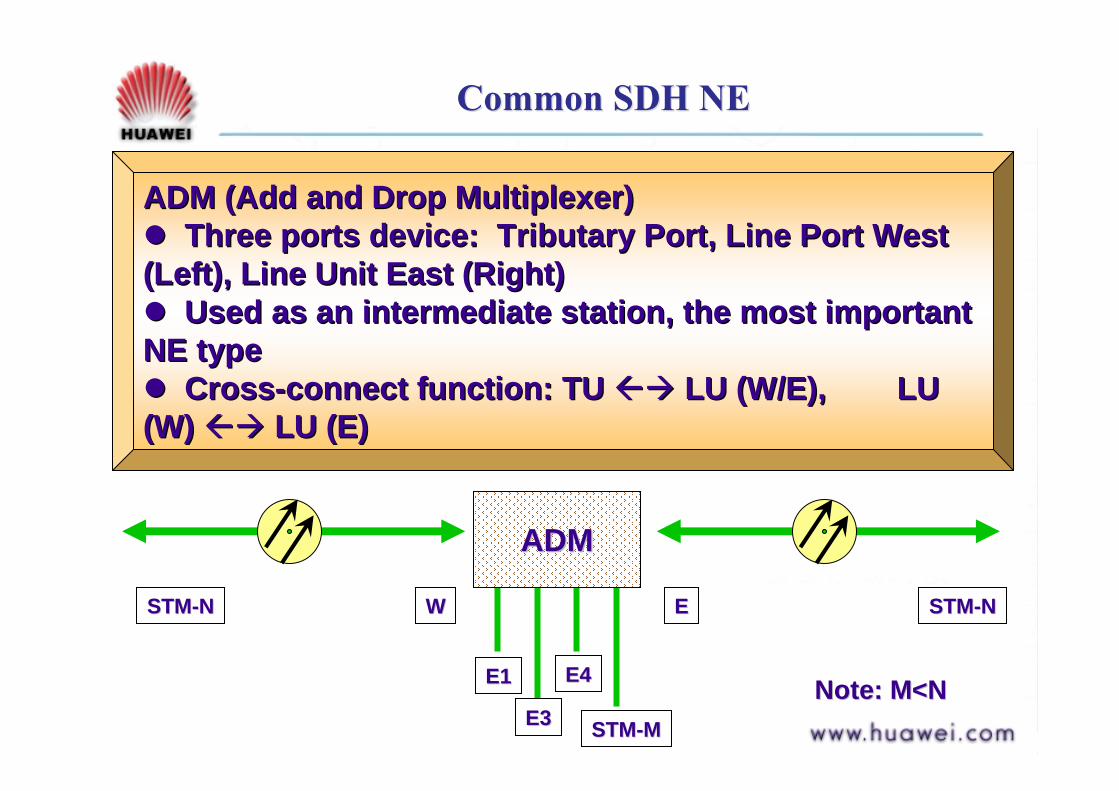
Common SDH NECommon SDH NE
ADM (Add and Drop Multiplexer)ADM (Add and Drop Multiplexer)!! Three ports device: Tributary Port, Line Port West Three ports device: Tributary Port, Line Port West (Left), Line Unit East (Right)(Left), Line Unit East (Right)!! Used as an intermediate station, the most important Used as an intermediate station, the most important NE typeNE type!! CrossCross--connect function: TU connect function: TU %"%" LU (W/E), LU LU (W/E), LU (W) (W) %"%" LU (E)LU (E)
ADMADM
E1E1
E3E3
E4E4
STMSTM--MM
STMSTM--NNEE
Note: M<NNote: M<N
STMSTM--NN WW

Common SDH NECommon SDH NE
Applications of TM & ADMApplications of TM & ADM
TM TMTM TM
E1E1
E3E3E4E4
STMSTM--MM
STMSTM--NNWW
Note: M<NNote: M<N
STMSTM--NNWW
TM ADM ADM TM
chain
ADM
ADM
ADM ADM
ring
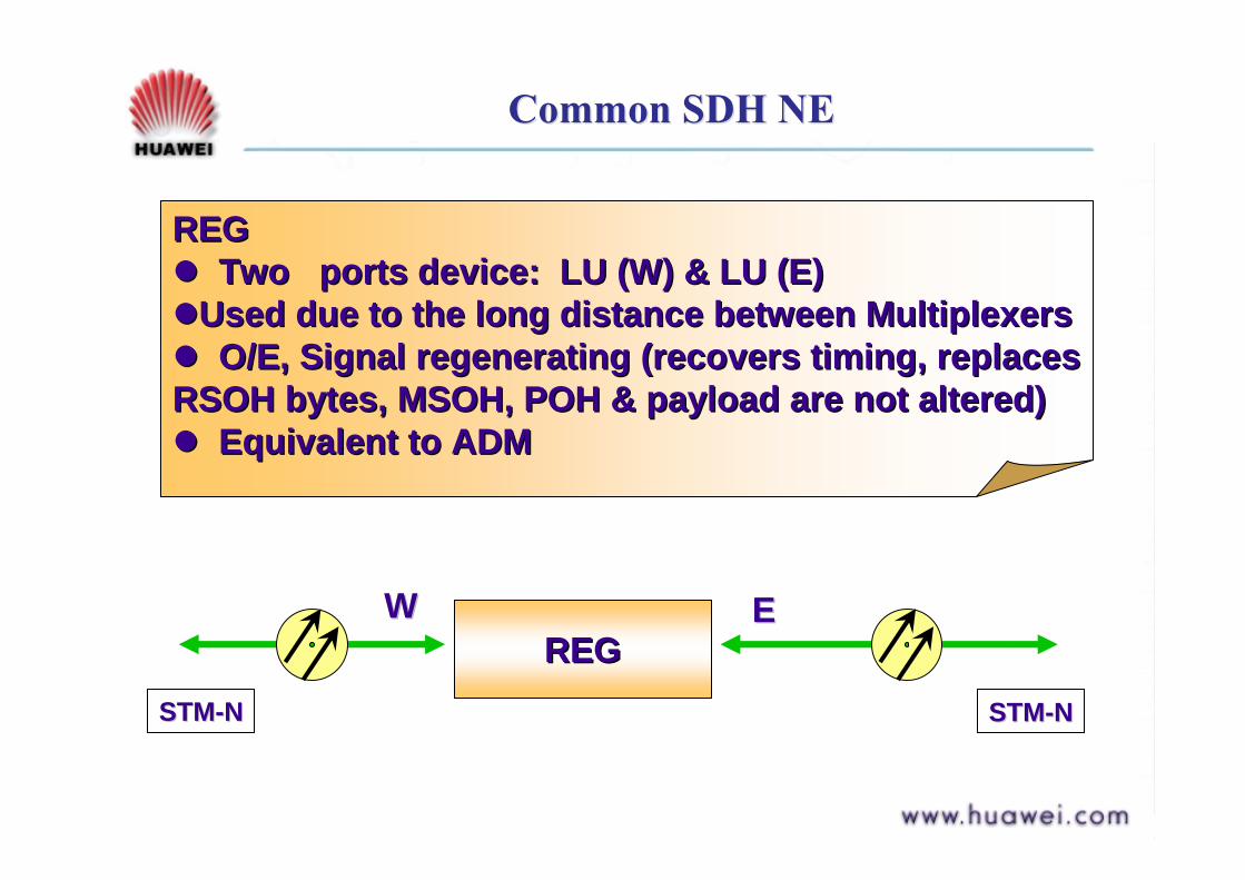
Common SDH NECommon SDH NE
REGREG!! Two ports device: LU (W) & LU (E)Two ports device: LU (W) & LU (E)!!Used due to the long distance between MultiplexersUsed due to the long distance between Multiplexers!! O/E, Signal regenerating (recovers timing, replaces O/E, Signal regenerating (recovers timing, replaces RSOH bytes, MSOH, POH & payload are not altered)RSOH bytes, MSOH, POH & payload are not altered)!! Equivalent to ADMEquivalent to ADM
REGREGWW EE
STMSTM--NN STMSTM--NN
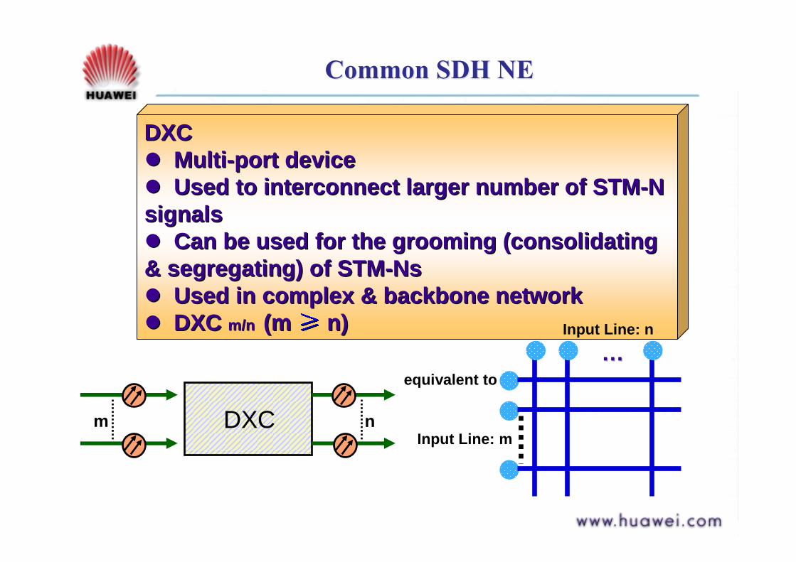
Common SDH NECommon SDH NE
DXCDXC!! MultiMulti--port deviceport device!! Used to interconnect larger number of STMUsed to interconnect larger number of STM--N N signalssignals!! Can be used for the grooming (consolidating Can be used for the grooming (consolidating & segregating) of STM& segregating) of STM--NsNs!! Used in complex & backbone networkUsed in complex & backbone network!! DXC DXC m/nm/n (m (m n) n)
DXCm n
equivalent to
Input Line: m
……Input Line: n

SDH Logical Functional BlocksSDH Logical Functional Blocks
SDH requires a SDH requires a unified Interfaceunified Interface
PurposePurpose
Realized differently by Realized differently by different vendorsdifferent vendors
ITUITU--T recommends a T recommends a unified basic functional unified basic functional block standard block standard

Logical Functional Block for SDH Equipment
Logical Functional Block for SDH Equipment
STM A B C D E F
F
FG
GH HI
NP
G.703
G.703
140Mb/s
2Mb/s34Mb/s
Note: Taking 2Mb/sas example
SPI RST
TTF
MSPMST MSA
HPCPPI
PPI
LPA
LPA
HPT
HPTLPT LPC HPA
OHA OHA InterfaceSEMF MCF
Q InterfaceF Interface
D4—D12 D1—D3
External SynchronousSignal Interface
HOA
HOI
LOI
w
L
JK
M
SETS SETPI

SPI Functional BlockSPI Functional Block
SPI: Synchronous Physical Interface" Implements interface
function" O/E, extracts timing signal
from STM-N" Monitors corresponding
alarm
SPISPI
ReceivingReceivingAA""BB
O/EO/EExtractExtractTimingTimingSignalSignal
Receive FailReceive FailRR--LOSLOS
TransmittingTransmittingBB""AA
E/OE/O
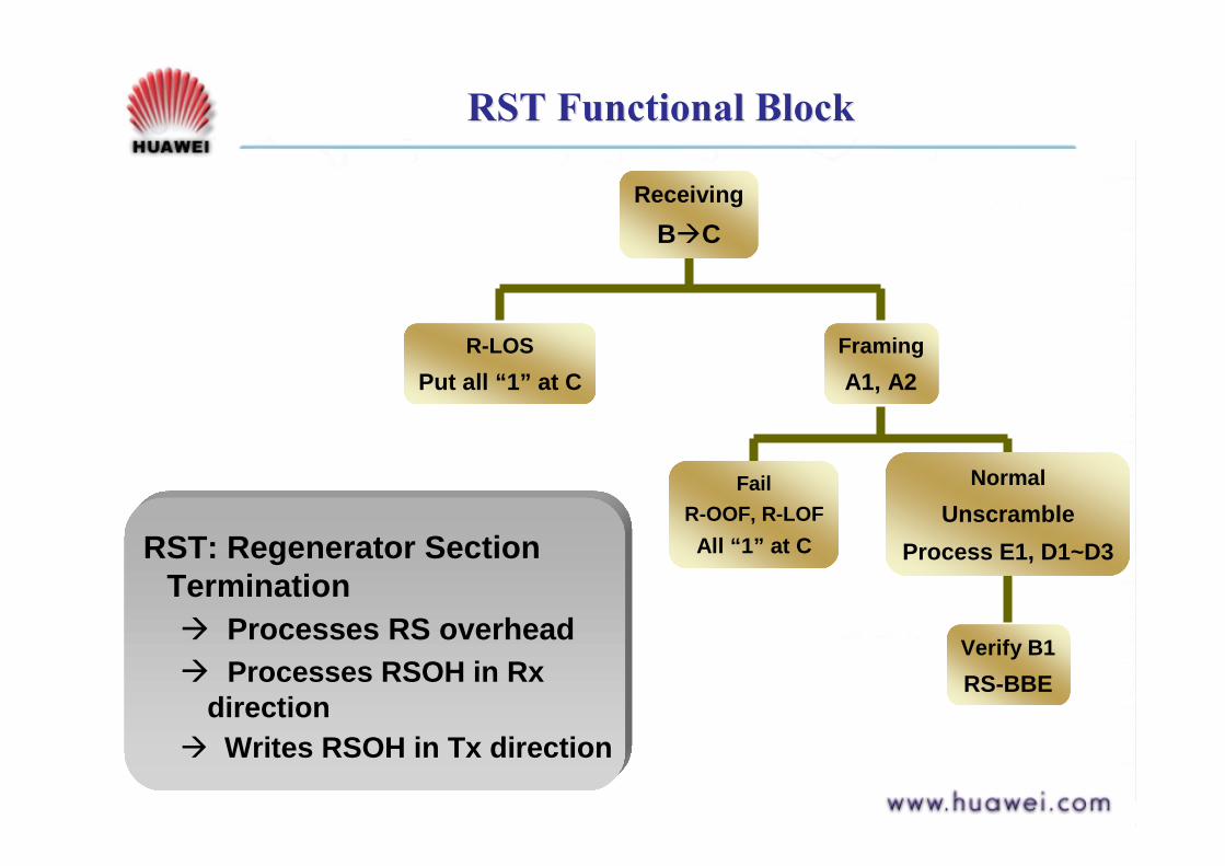
RST Functional BlockRST Functional Block
RST: Regenerator Section Termination " Processes RS overhead" Processes RSOH in Rx
direction" Writes RSOH in Tx direction
ReceivingB"C
R-LOSPut all “1” at C
FramingA1, A2
FailR-OOF, R-LOFAll “1” at C
NormalUnscramble
Process E1, D1~D3
Verify B1RS-BBE
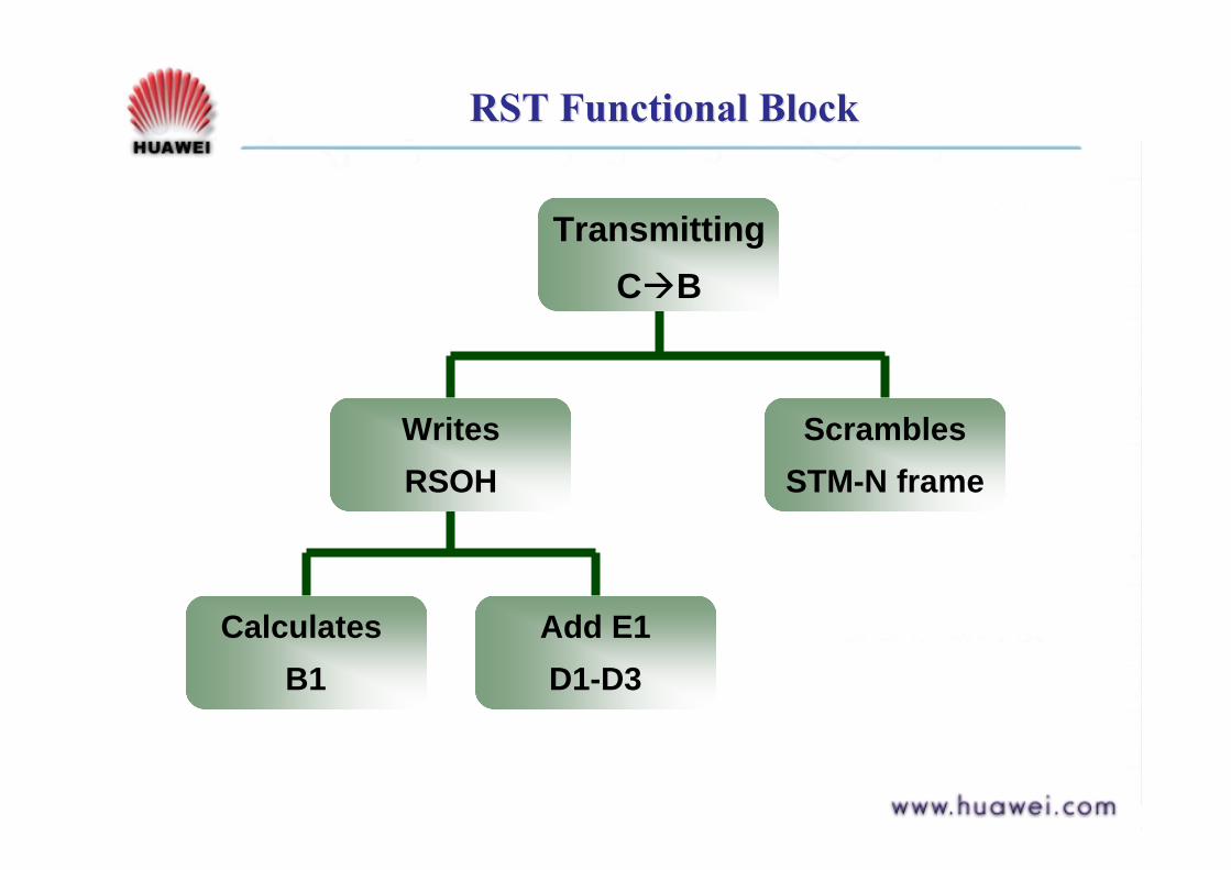
RST Functional BlockRST Functional Block
TransmittingC"B
WritesRSOH
Calculates B1
Add E1D1-D3
ScramblesSTM-N frame
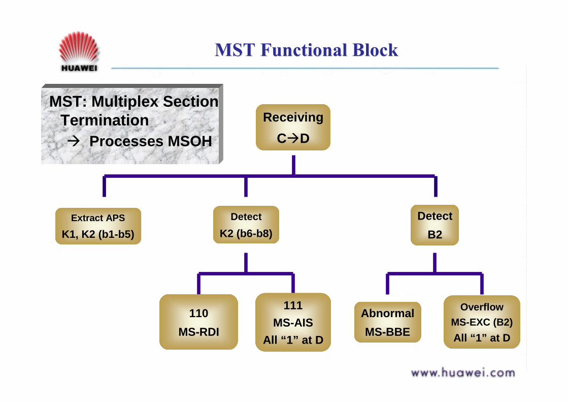
MST Functional BlockMST Functional Block
MST: Multiplex Section Termination " Processes MSOH
ReceivingC"D
Extract APSK1, K2 (b1-b5)
DetectK2 (b6-b8)
110MS-RDI
111MS-AIS
All “1” at D
DetectB2
AbnormalMS-BBE
OverflowMS-EXC (B2)All “1” at D
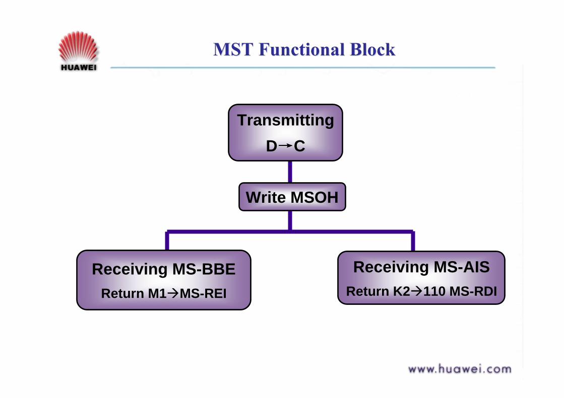
MST Functional BlockMST Functional Block
TransmittingD C
Write MSOH
Receiving MS-BBEReturn M1"MS-REI
Receiving MS-AISReturn K2"110 MS-RDI

MST Functional BlockMST Functional Block
Signal frame structure at reference point D
MST RST SPI MSTRSTSPI
RS (regenerator section)MS (multiplex section)
Concept of RS, MS
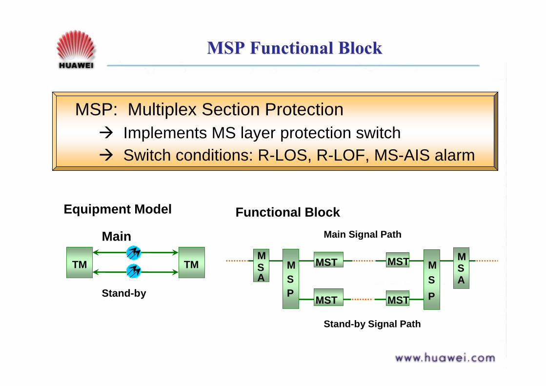
MSP Functional BlockMSP Functional Block
MSP: Multiplex Section Protection " Implements MS layer protection switch" Switch conditions: R-LOS, R-LOF, MS-AIS alarm
Main
Stand-by
TM TM
Equipment Model Functional Block
MSA
MSA
MSP
MSP
MST MST
MST MST
Main Signal Path
Stand-by Signal Path

MSA Functional BlockMSA Functional Block
MSA: Multiplex Section Adaptation " Implements AUG to
VC-4 or VC-4 to AUG conversion
ReceivingE"F
De-interleavedAUG " N AU-4
ReadAU-PTR
H1H2H3 are all “1”AU-AIS
All “1” at F
Invalid pointer or 8 NDFAU-LOP
All “1” at F

MSA Functional BlockMSA Functional Block
TransmittingF " E
WritesAU-PTR
Byte interleavedN AU- 4 " AUG
Signal frame structure at Point F
VC-4
1 2611
9

Functional BlocksFunctional Blocks
HPC: HighHPC: High--Order Path CrossOrder Path Cross--connectconnect"" CrossCross--connect Matrix control & connect Matrix control & Implementation only for VCImplementation only for VC--44"" Only chooses the route, does not Only chooses the route, does not process signalsprocess signals
HPT: HighHPT: High--Order Path TerminationOrder Path Termination"" Processes HOProcesses HO--POH in VCPOH in VC--44"" VCVC--4 Real4 Real--Time monitoringTime monitoring

Verify B3Verify B3Invalid Invalid
"" HPHP--BBEBBE
HPT Functional BlockHPT Functional Block
ReceivingReceivingF F "" GG
Detect J1Detect J1MismatchMismatch"" HPHP--TIMTIM
Detect C2Detect C2MismatchMismatch"" HPHP--SLMSLM
"" 00H: HP00H: HP--UNEQUNEQ
All All ““11”” at Gat G
Transmit H4Transmit H4to HPAto HPA
All All ““11”” at Gat G
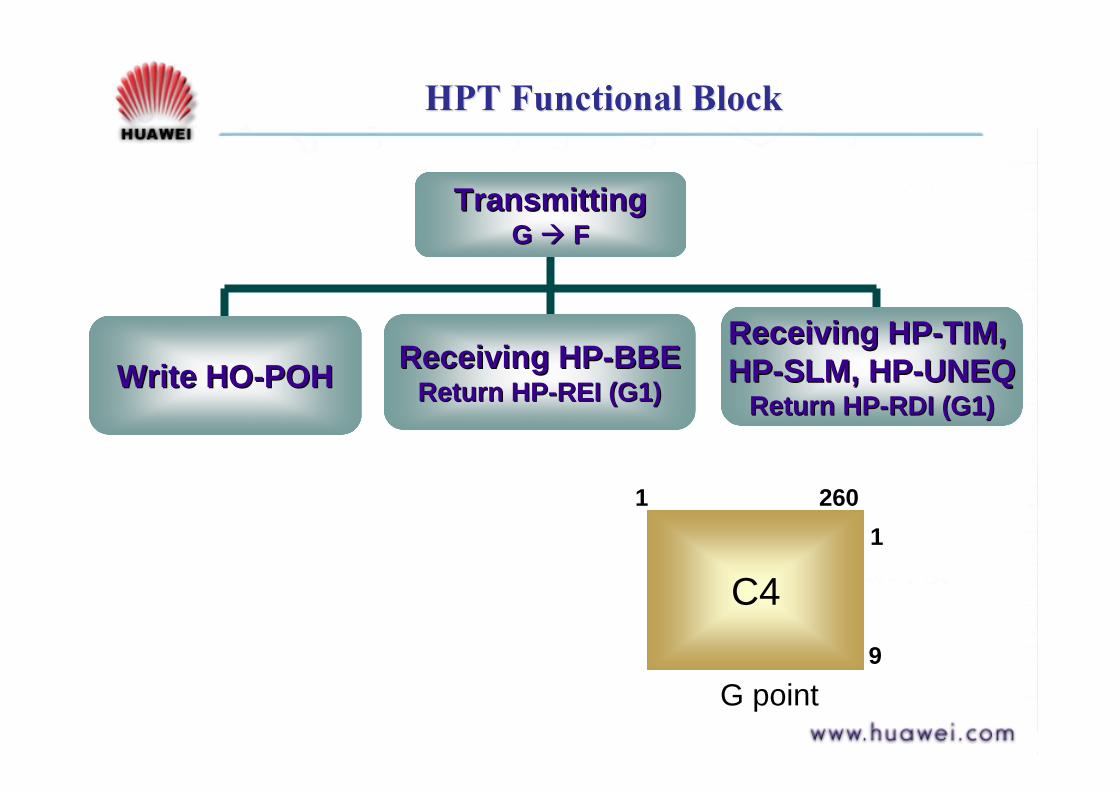
HPT Functional BlockHPT Functional Block
TransmittingTransmittingG G "" FF
Write HOWrite HO--POHPOH Receiving HPReceiving HP--BBEBBEReturn HPReturn HP--REI (G1)REI (G1)
Receiving HPReceiving HP--TIM, TIM, HPHP--SLM, HPSLM, HP--UNEQUNEQ
Return HPReturn HP--RDI (G1)RDI (G1)
G point
C4
1 2601
9
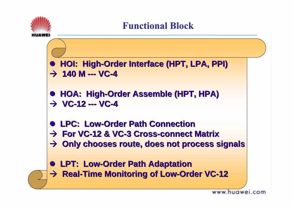
Functional BlockFunctional Block
!! HOI: HighHOI: High--Order Interface (HPT, LPA, PPI)Order Interface (HPT, LPA, PPI)"" 140 M 140 M ------ VCVC--44
!! HOA: HighHOA: High--Order Assemble (HPT, HPA)Order Assemble (HPT, HPA)"" VCVC--12 12 ------ VCVC--44
!! LPC: LowLPC: Low--Order Path ConnectionOrder Path Connection"" For VCFor VC--12 & VC12 & VC--3 Cross3 Cross--connect Matrixconnect Matrix"" Only chooses route, does not process signalsOnly chooses route, does not process signals
!! LPT: LowLPT: Low--Order Path AdaptationOrder Path Adaptation"" RealReal--Time Monitoring of LowTime Monitoring of Low--Order VCOrder VC--1212

Functional BlockFunctional Block
LPA: LowLPA: Low--Order Path AdaptationOrder Path Adaptation"" Implements pack/unpack and restores original signalImplements pack/unpack and restores original signal"" PDH <PDH <------> C> C
PPI: PDH Physical InterfacePPI: PDH Physical Interface"" Extract PDH tributary signal timingExtract PDH tributary signal timing"" Code pattern conversionCode pattern conversion"" Interface between device and PDH lineInterface between device and PDH line
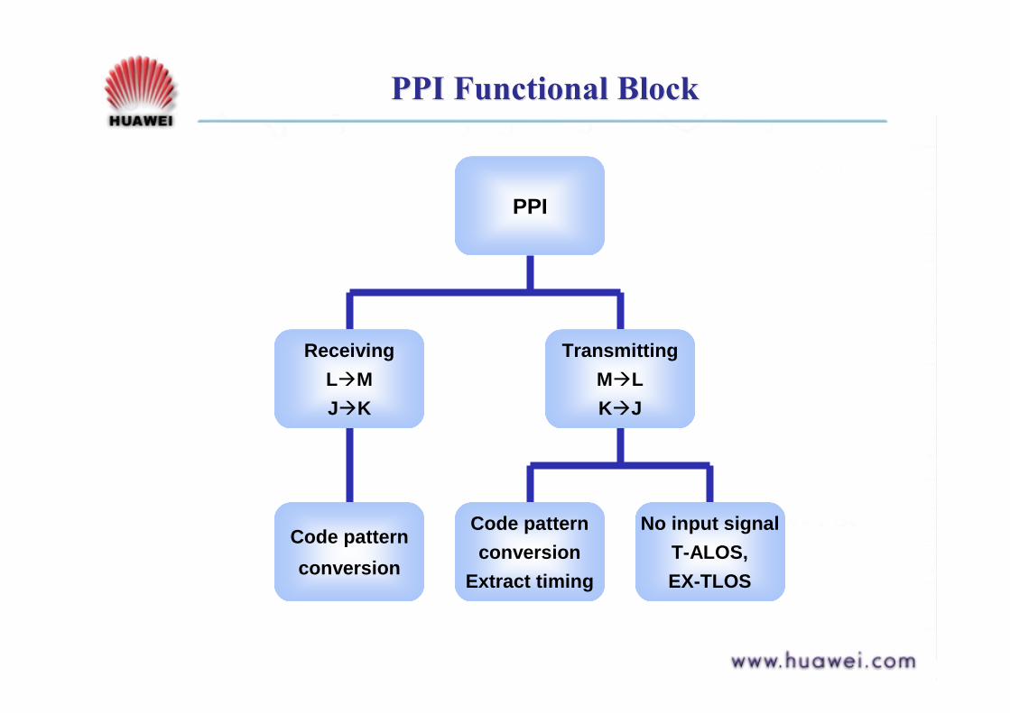
PPI Functional BlockPPI Functional Block
PPI
ReceivingL"MJ"K
Code patternconversion
TransmittingM"LK"J
Code patternconversion
Extract timing
No input signalT-ALOS,EX-TLOS

HPA Functional BlockHPA Functional Block
ReceivingG"H
De-interleavedC4 " 63XTU-12
ReadTU-PTR
V1V2V3 are all “1”TU-AIS
All “1” at H
Invalid pointer or 8 NDFTU-LOP
All “1” at H
HPA: High order Path Adaptation
" Implements C4 to VC-12 conversion

HPA Functional BlockHPA Functional Block
TransmittingH"G
TransmittingTransmittingHH""GG
Write PointerTU-PTR, VC-12"TU12
Write PointerWrite PointerTUTU--PTR, VCPTR, VC--1212""TU12TU12
Byte InterleaveTU12"C-4
Byte InterleaveByte InterleaveTU12TU12""CC--44

LPT Functional BlockLPT Functional Block
LPTLPT
ReceivingReceivingHH""II
Detect V5Detect V5LPLP--BBEBBE
LPLP--SLM, LPSLM, LP--UNEQUNEQ
TransmittingTransmittingII""HH
Write LOWrite LO--POHPOHReceive LPReceive LP--BBE, Return LPBBE, Return LP--REIREI
Receive LPReceive LP--SLM, UNEQ, Return LPSLM, UNEQ, Return LP--RDIRDI
LPT: LowLPT: Low--Order Path TerminationOrder Path Termination"" Process LOProcess LO--POHPOH
Auxiliary Functional BlocksAuxiliary Functional Blocks
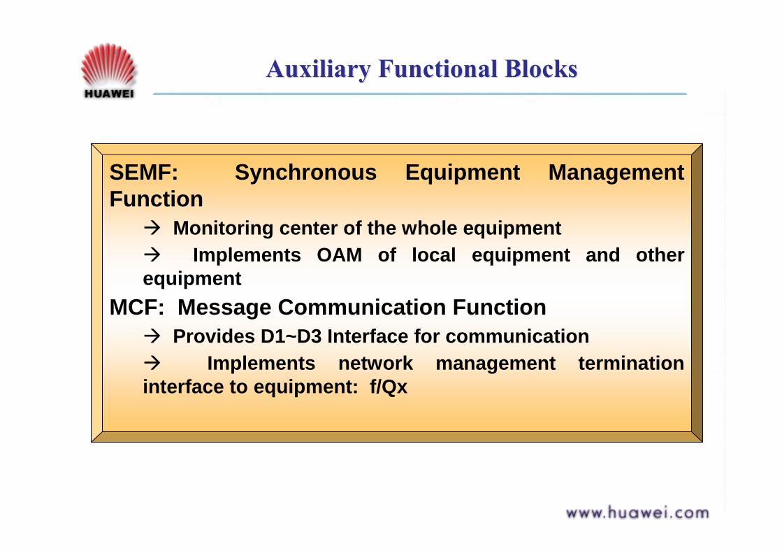
SEMF: Synchronous Equipment Management Function
" Monitoring center of the whole equipment" Implements OAM of local equipment and other equipment
MCF: Message Communication Function" Provides D1~D3 Interface for communication" Implements network management termination interface to equipment: f/Qx
Auxiliary Functional BlocksAuxiliary Functional Blocks
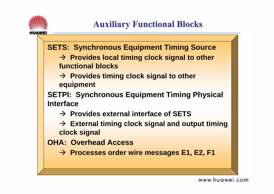
SETS: Synchronous Equipment Timing Source" Provides local timing clock signal to other functional blocks" Provides timing clock signal to other equipment
SETPI: Synchronous Equipment Timing Physical Interface
" Provides external interface of SETS" External timing clock signal and output timing clock signal
OHA: Overhead Access" Processes order wire messages E1, E2, F1
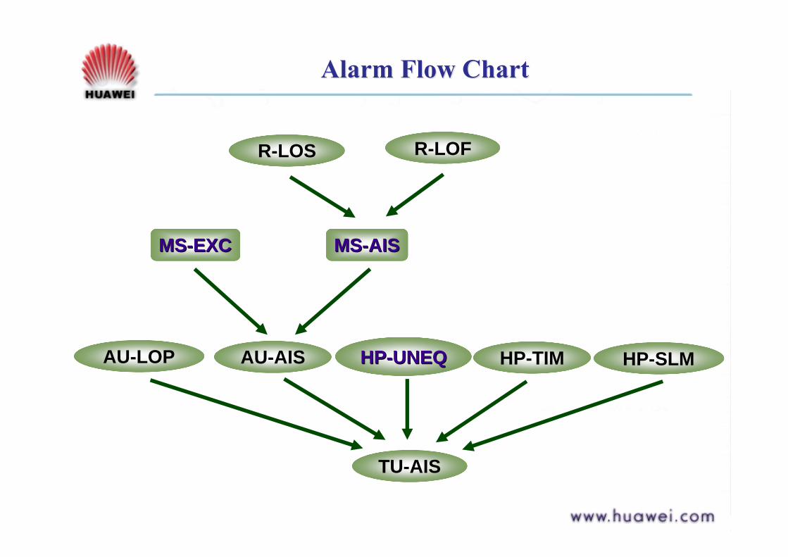
Alarm Flow ChartAlarm Flow Chart
TU-AIS
AU-AIS HPHP--UNEQUNEQ HP-TIM HP-SLMAU-LOP
R-LOS R-LOF
MSMS--AISAISMSMS--EXCEXC