Embed Size (px)
Citation preview
Copyright © Siemens AG 2010. All rights reserved
OTC 2010 X-pert Center
Subsea Power Grid
Bjørn Einar Brath
Copyright © Siemens AG 2010. All rights reserved
Copyright © Siemens AG 2010. All rights reserved
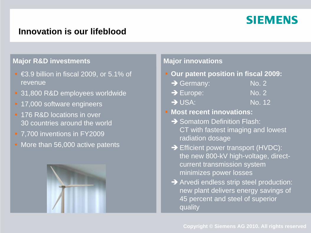
Major innovationsMajor R&D investments
Our patent position in fiscal 2009: Germany: No. 2Europe: No. 2USA: No. 12 Most recent innovations:Somatom Definition Flash:
CT with fastest imaging and lowest radiation dosage
Efficient power transport (HVDC): the new 800-kV high-voltage, direct- current transmission system minimizes power losses
Arvedi endless strip steel production: new plant delivers energy savings of 45 percent and steel of superior quality
€3.9 billion in fiscal 2009, or 5.1% of revenue
31,800 R&D employees worldwide 17,000 software engineers 176 R&D locations in over
30 countries around the world 7,700 inventions in FY2009 More than 56,000 active patents
Innovation is our lifeblood
Copyright © Siemens AG 2010. All rights reserved
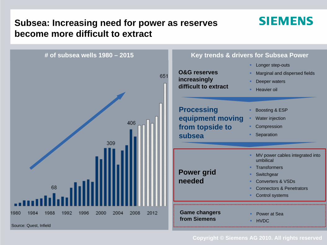
Subsea: Increasing need for power as reserves become more difficult to extract
Key trends & drivers for Subsea Power Longer step-outs
Marginal and dispersed fields
Deeper waters
Heavier oil
O&G reserves increasingly difficult to extract
Boosting & ESP
Water injection
Compression
Separation
Processing equipment moving from topside to subsea
Source: Quest, Infield
# of subsea wells 1980 – 2015
MV power cables integrated into umbilical
Transformers Switchgear Converters & VSDs Connectors & Penetrators Control systems
Power grid needed
Power at Sea HVDC
Game changers from Siemens

Copyright © Siemens AG 2010. All rights reserved
Offshore Global Organization
BC USA, Houston
BC Brazil
BC China
BC Singapore
BC Netherlands
RussiaCanada
Middle EastMexico India
AustraliaSouth Africa
Business CentersE O CS Headquarters Engineering CentersRegional Company
HQ Norway
Subsea Center of Competences
Copyright © Siemens AG 2010. All rights reserved
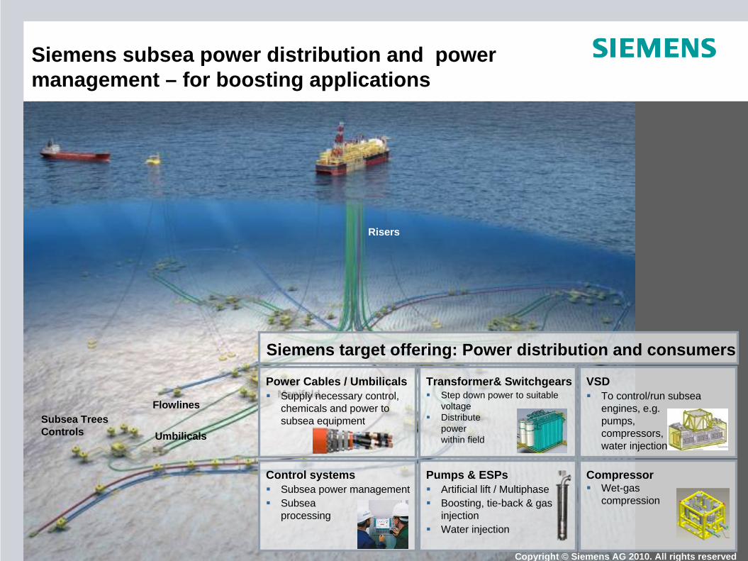
Risers
Manifold
Subsea TreesControls
Flowlines
Umbilicals
Transformer& Switchgears Step down power to suitable
voltage Distribute
power within field
VSD To control/run subsea
engines, e.g. pumps, compressors, water injection
Power Cables / Umbilicals Supply necessary control,
chemicals and power to subsea equipment
Pumps & ESPs Artificial lift / Multiphase Boosting, tie-back & gas
injection Water injection
Compressor Wet-gas
compression
Control systems Subsea power management Subsea
processing
Siemens target offering: Power distribution and consumers
Siemens subsea power distribution and power management – for boosting applications
Copyright © Siemens AG 2010. All rights reserved
Copyright © Siemens AG 2010. All rights reserved
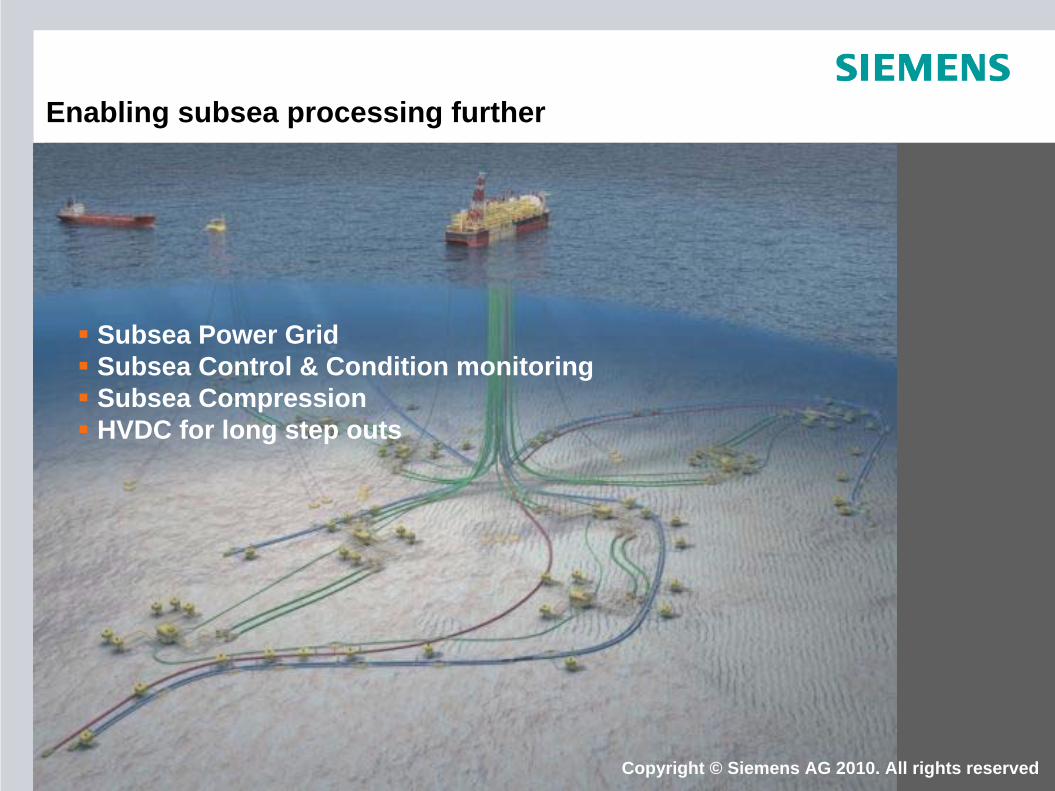
Subsea Power Grid Subsea Control & Condition monitoring Subsea Compression HVDC for long step outs
Enabling subsea processing further
Copyright © Siemens AG 2010. All rights reserved
Copyright © Siemens AG 2010. All rights reserved
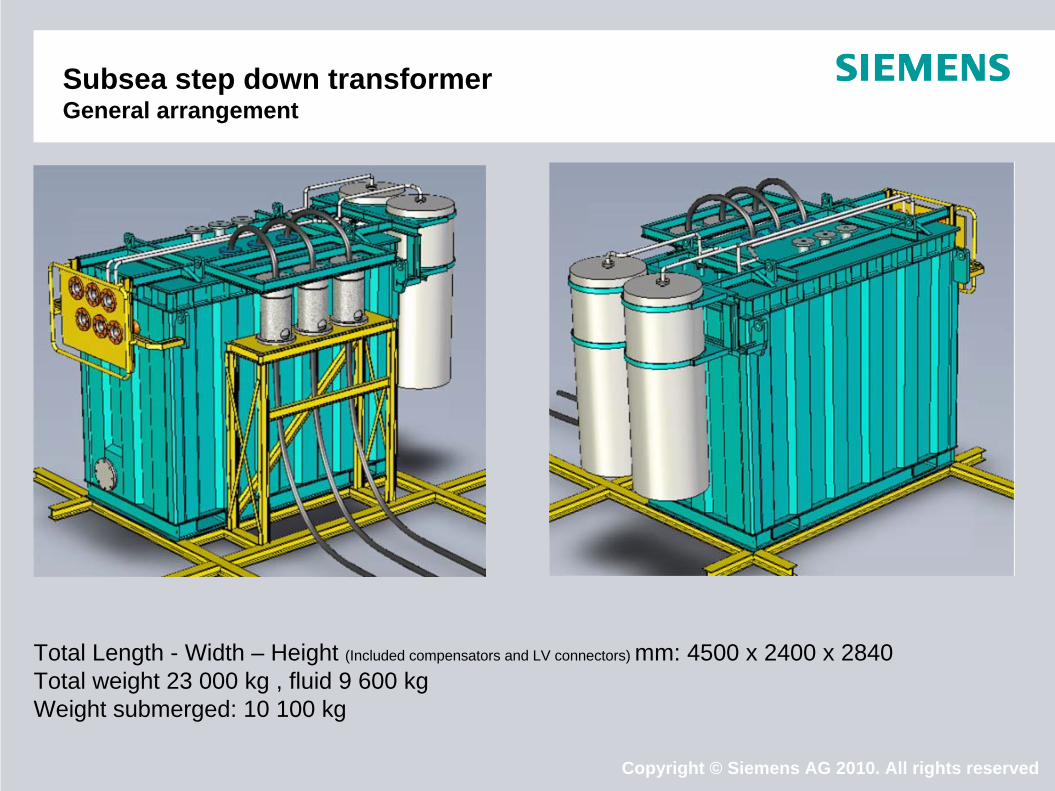
Subsea step down transformer General arrangement
Total Length - Width – Height (Included compensators and LV connectors) mm: 4500 x 2400 x 2840 Total weight 23 000 kg , fluid 9 600 kg Weight submerged: 10 100 kg
Copyright © Siemens AG 2010. All rights reserved
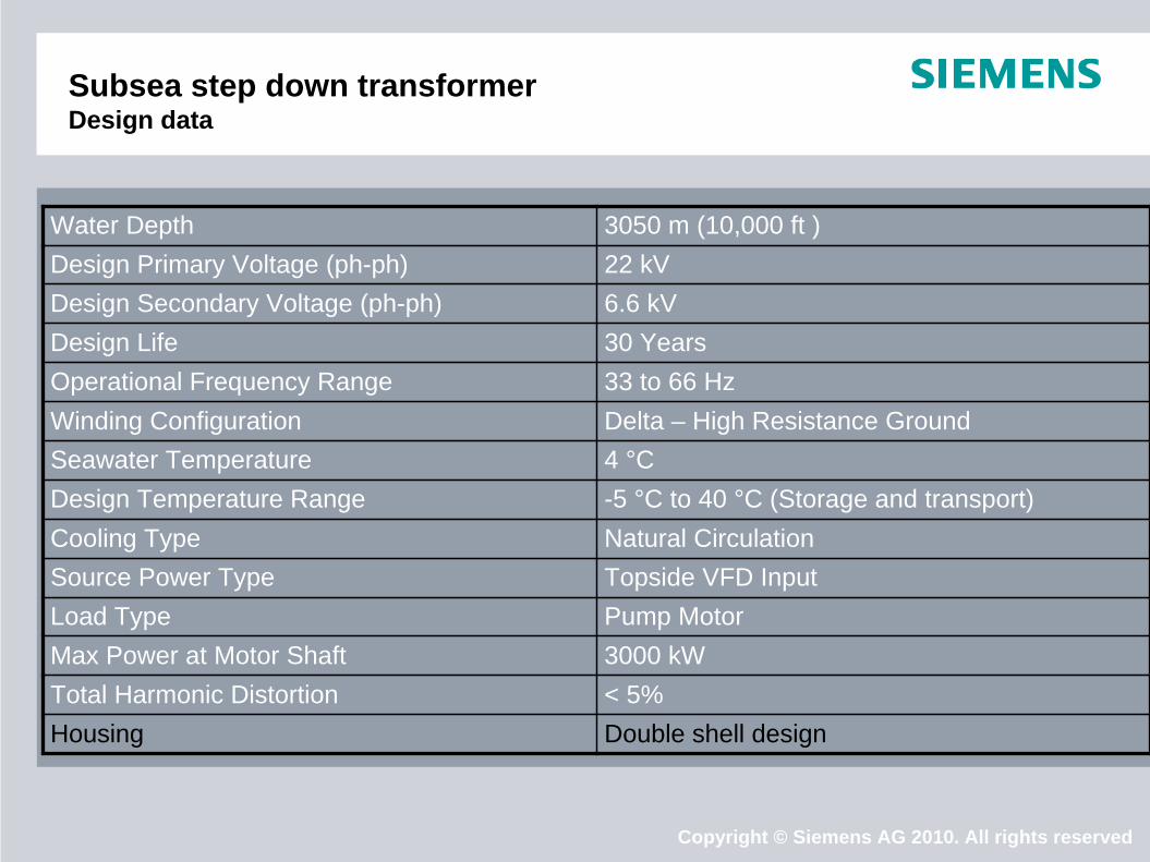
Subsea step down transformer Design data
Water Depth 3050 m (10,000 ft )Design Primary Voltage (ph-ph) 22 kV Design Secondary Voltage (ph-ph) 6.6 kV Design Life 30 Years Operational Frequency Range 33 to 66 Hz Winding Configuration Delta – High Resistance Ground Seawater Temperature 4 °C Design Temperature Range -5 °C to 40 °C (Storage and transport) Cooling Type Natural Circulation Source Power Type Topside VFD Input Load Type Pump Motor Max Power at Motor Shaft 3000 kW Total Harmonic Distortion < 5%Housing Double shell design
Copyright © Siemens AG 2010. All rights reserved
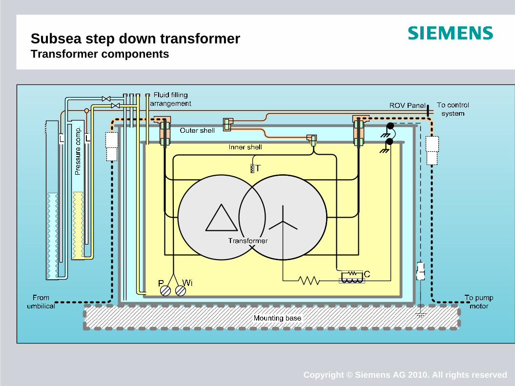
Subsea step down transformer Transformer components
Copyright © Siemens AG 2010. All rights reserved
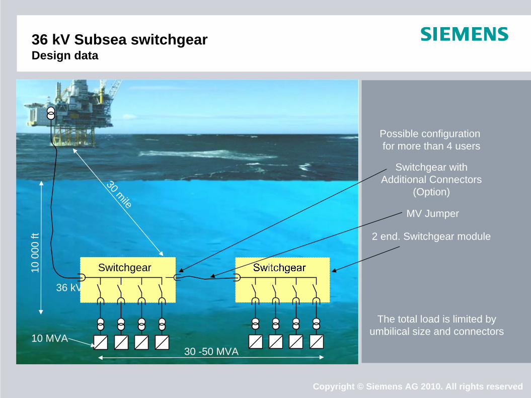
36 kV Subsea switchgear Design data
Switchgear
30 mile
10 0
00 ft
36 kV
10 MVA
Possible configuration for more than 4 users
Switchgear with Additional Connectors
(Option)
2 end. Switchgear module
MV Jumper
The total load is limited by umbilical size and connectors
30 -50 MVA
Copyright © Siemens AG 2010. All rights reserved
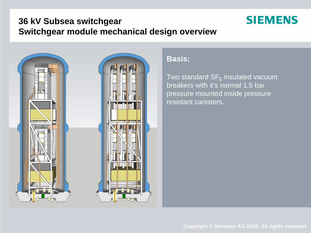
36 kV Subsea switchgear Switchgear module mechanical design overview
Basis:
Two standard SF6 insulated vacuum breakers with it’s normal 1.5 bar pressure mounted inside pressure resistant canisters.
Copyright © Siemens AG 2010. All rights reserved
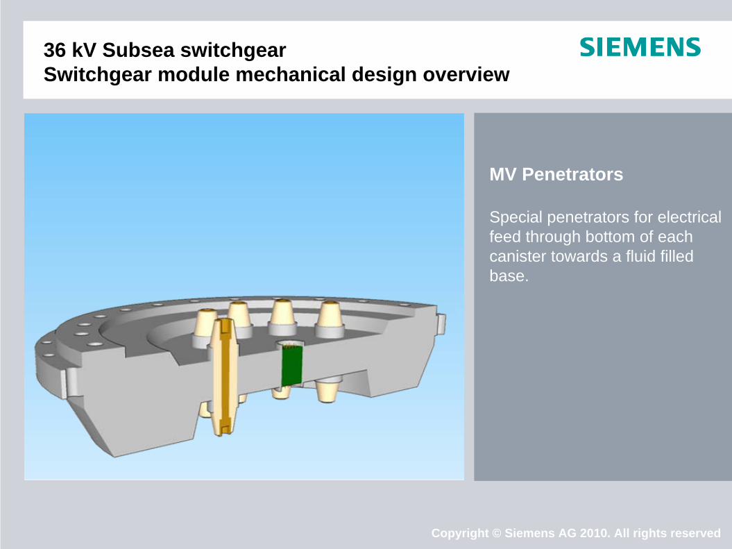
36 kV Subsea switchgear Switchgear module mechanical design overview
MV Penetrators
Special penetrators for electrical feed through bottom of each canister towards a fluid filled base.
Copyright © Siemens AG 2010. All rights reserved
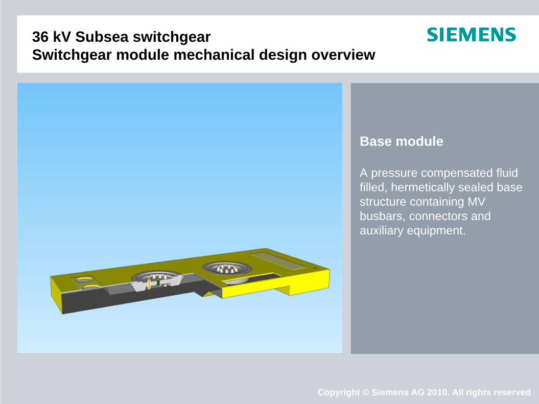
36 kV Subsea switchgear Switchgear module mechanical design overview
Base module
A pressure compensated fluid filled, hermetically sealed base structure containing MV busbars, connectors and auxiliary equipment.
Copyright © Siemens AG 2010. All rights reserved
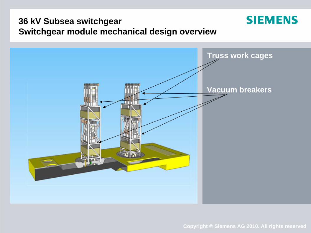
36 kV Subsea switchgear Switchgear module mechanical design overview
Truss work cages
Vacuum breakers

Copyright © Siemens AG 2010. All rights reserved
36 kV Subsea switchgear Switchgear module mechanical design overview
Control
Control system and protective relays are kept in a separate container, which can be located inside the canister,
or in the base module
as a retrievable unit outside,
Copyright © Siemens AG 2010. All rights reserved
36 kV Subsea switchgear Switchgear module mechanical design overview
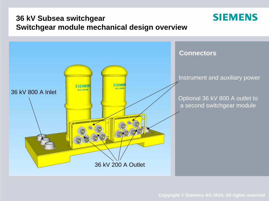
Connectors
36 kV 800 A Inlet
36 kV 200 A Outlet
Instrument and auxiliary power
Optional 36 kV 800 A outlet to a second switchgear module
Copyright © Siemens AG 2010. All rights reserved
36 kV Subsea switchgear Switchgear module mechanical design overview
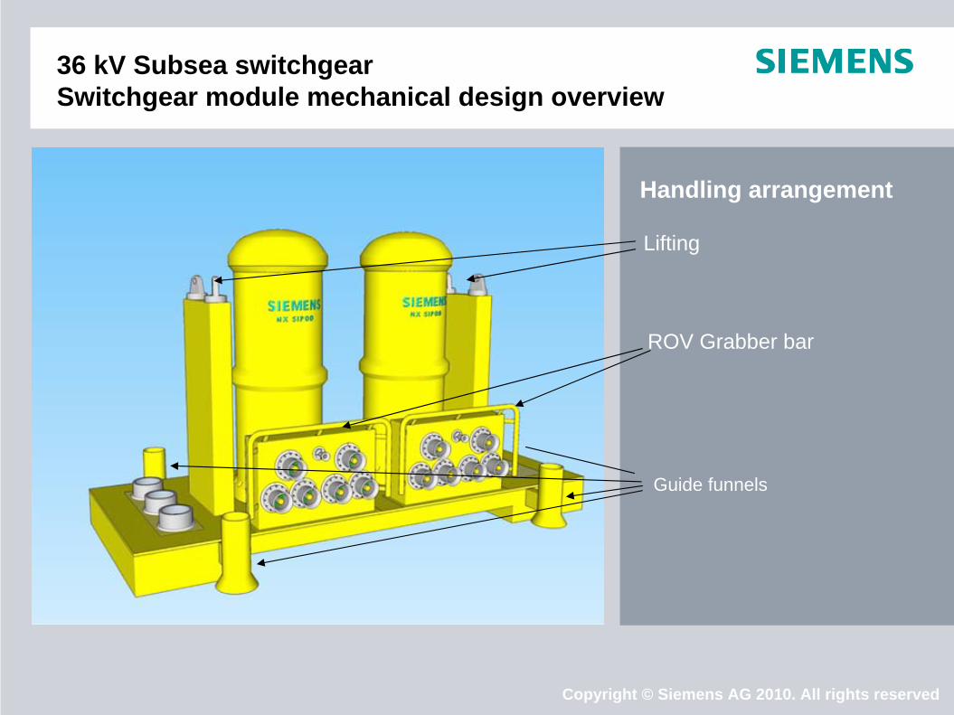
Handling arrangement
Lifting
Guide funnels
ROV Grabber bar
Copyright © Siemens AG 2010. All rights reserved
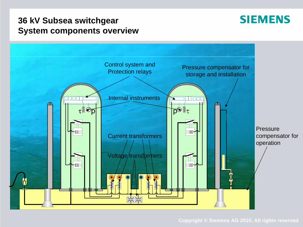
36 kV Subsea switchgear System components overview
Control system andProtection relays
Internal instruments
Current transformers
Voltage transformers
Pressure compensator for storage and installation
Pressure compensator for operation
Copyright © Siemens AG 2010. All rights reserved
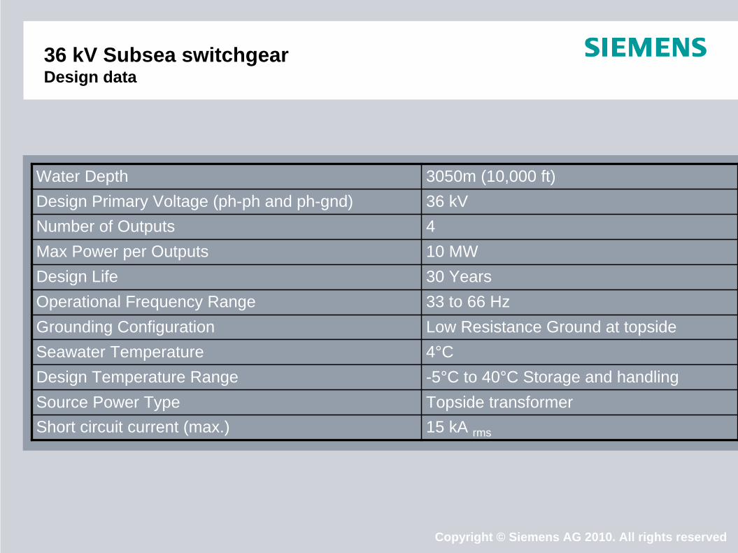
36 kV Subsea switchgear Design data
Water Depth 3050m (10,000 ft) Design Primary Voltage (ph-ph and ph-gnd) 36 kV Number of Outputs 4 Max Power per Outputs 10 MWDesign Life 30 Years Operational Frequency Range 33 to 66 Hz Grounding Configuration Low Resistance Ground at topsideSeawater Temperature 4°C Design Temperature Range -5°C to 40°C Storage and handling Source Power Type Topside transformer Short circuit current (max.) 15 kA rms

Copyright © Siemens AG 2010. All rights reservedSlide 20
Subsea VSD Enclosure
TransformerThree 3-phase transformers.In the same enclosure as the VSD. Reducing weight and the # of connectors and penetrators.
VSD phase modules6 power cells in each phasemodule
9120
2720
2610
Approx. 53 Metric ton
Copyright © Siemens AG 2010. All rights reservedSlide 21
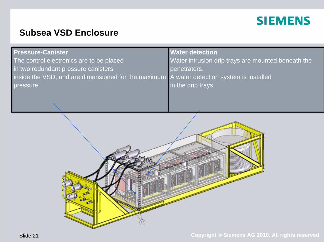
Subsea VSD Enclosure
Pressure-CanisterThe control electronics are to be placed in two redundant pressure canisters inside the VSD, and are dimensioned for the maximum pressure.
Water detectionWater intrusion drip trays are mounted beneath the penetrators. A water detection system is installed in the drip trays.

Copyright © Siemens AG 2010. All rights reservedSlide 22
Subsea VSD study Design data
Water Depth (m) 3050 m (10 000 ft)Max Distance to Load (km) 5
Nominal Operating Voltage (kV) 6,6
Power Output Requirement (MVA) 4,0
Cos motor, (power factor) TBD
Power Transmission 3Ø AC
Input Frequency Range (Hz) 50 – 60
Output Frequency Range (Hz) 0 – 100
Landing Speed 0.5m/s
Shock 3g
Ambient sea water temp. deg ºC 0-10Design life (Years) 30
Penetrator Specification Wetmate (Statoil Specification TD0153)

Copyright © Siemens AG 2010. All rights reserved
Power Management and Performance- / Condition Monitoring
To ensure and maintain the availability of the Subsea Power Grid, a dedicated Power management, performance/condition based monitoring system to be provided. Main functionality to be covered: Monitoring of Power Grid incl. equipment to facilitate cost saving, lifetime extension,
reduced maintenance and increased availability Network Control / Network monitoring (black-out prevention, load shedding/limitation, etc.)
Automated restart sequence after black out Operational key data statistics (key measurements, # of operations, peak current etc.)
Early detection of potential failures Reporting of graceful degradation of high available systems and components (typical loss of
power electronic cells in VSD etc.)
Model based prediction of remaining life (availability) of power systems and components Remote monitoring / Fault diagnosis, condition & performance reporting to topside/shore
operational center
Copyright © Siemens AG 2010. All rights reserved
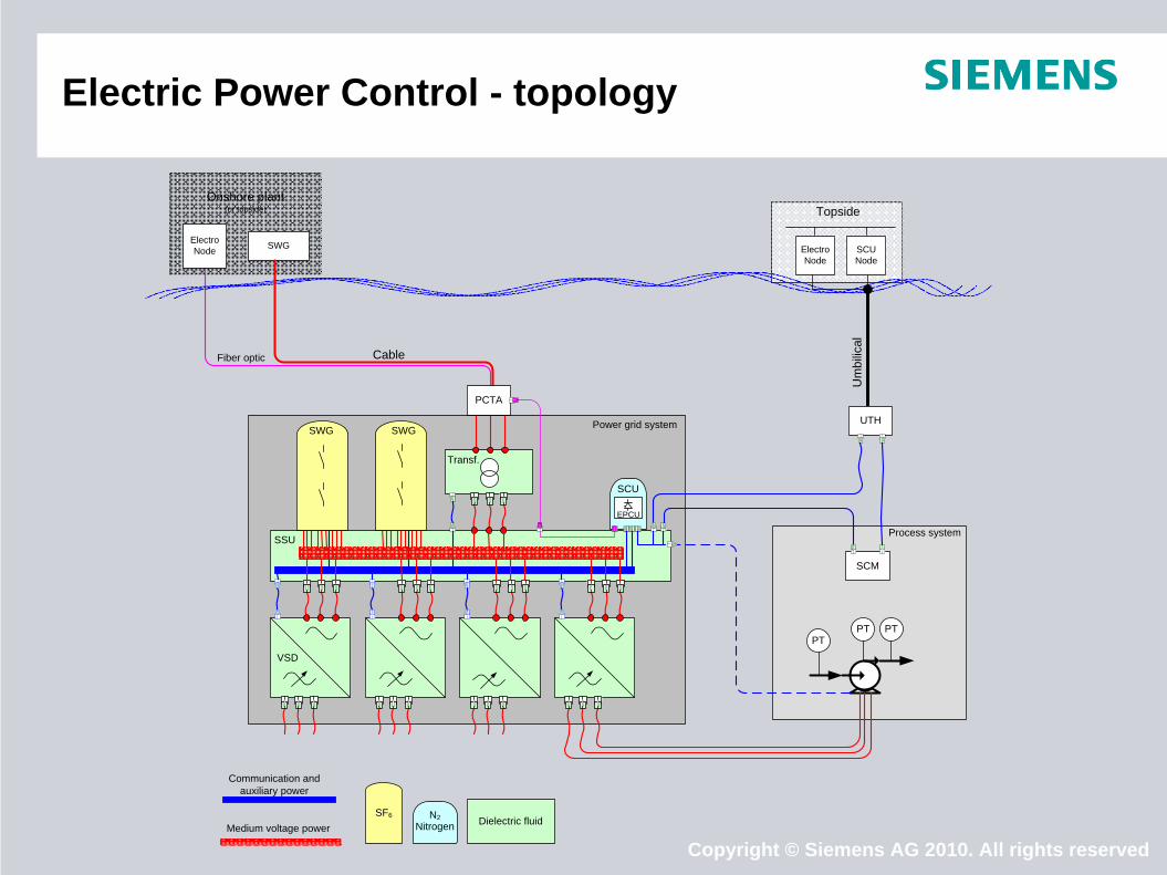
Electric Power Control - topology
Onshore plant (or topside)
Fiber optic
SWGElectro Node
Topside
Electro Node
SCU Node
PCTA
PTPT
PT
SCM
UTH
VSD
SSU
Transf.
SCU
SWG SWG
Process system
Cable
Um
bilic
al
Power grid system
Communication and auxiliary power
Medium voltage powerDielectric fluidN2
NitrogenSF6
EPCU
Copyright © Siemens AG 2010. All rights reservedCopyright © Siemens AG 2010. All rights reserved
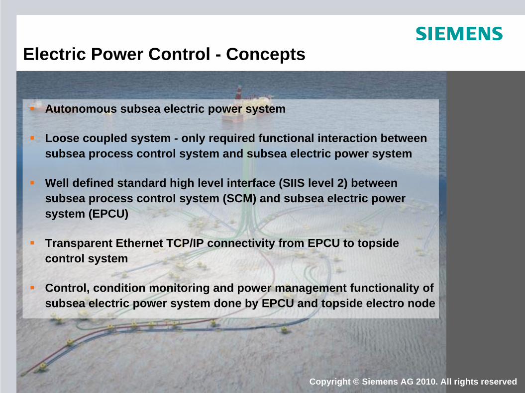
Electric Power Control - Concepts
Autonomous subsea electric power system
Loose coupled system - only required functional interaction between subsea process control system and subsea electric power system
Well defined standard high level interface (SIIS level 2) between subsea process control system (SCM) and subsea electric power system (EPCU)
Transparent Ethernet TCP/IP connectivity from EPCU to topside control system
Control, condition monitoring and power management functionality of subsea electric power system done by EPCU and topside electro node

Copyright © Siemens AG 2010. All rights reserved
No low level interfacing required - saves time and engineering cost
Standard high level interface between subsea process control system and subsea electric power system yields interoperability
Avoid unnecessary coupled system given by communication through subsea process control system (2 levels of tag mapping)
Autonomous subsea electric power system with seamless integration with Siemens topside control system yields an integrated total power management solution for the asset
Functionality in subsea electric power system may be modified in operation without involvement from subsea process control system vendor
Copyright © Siemens AG 2010. All rights reserved
Electric Power Control - Benefits

Copyright © Siemens AG 2010. All rights reserved
Subsea Standardization - InterfacesTopside
Profibus or Ethernetcommunication
Member of SIIS
Copyright © Siemens AG 2010. All rights reserved
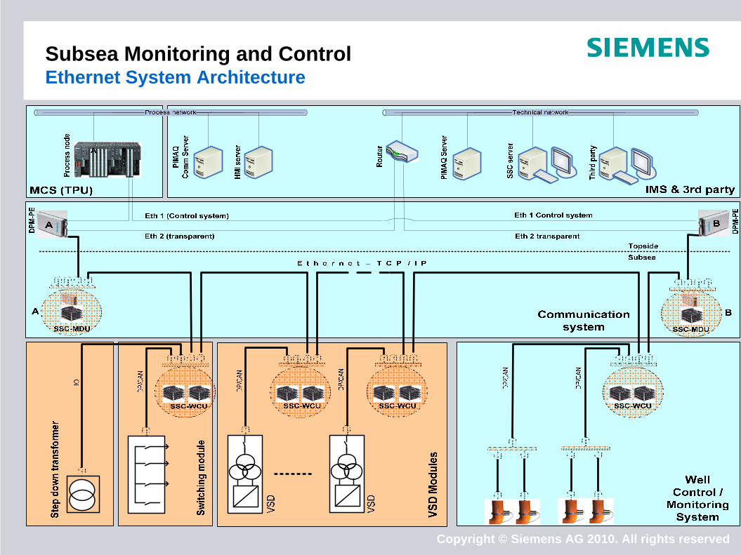
Subsea Monitoring and Control Ethernet System Architecture
Copyright © Siemens AG 2010. All rights reserved
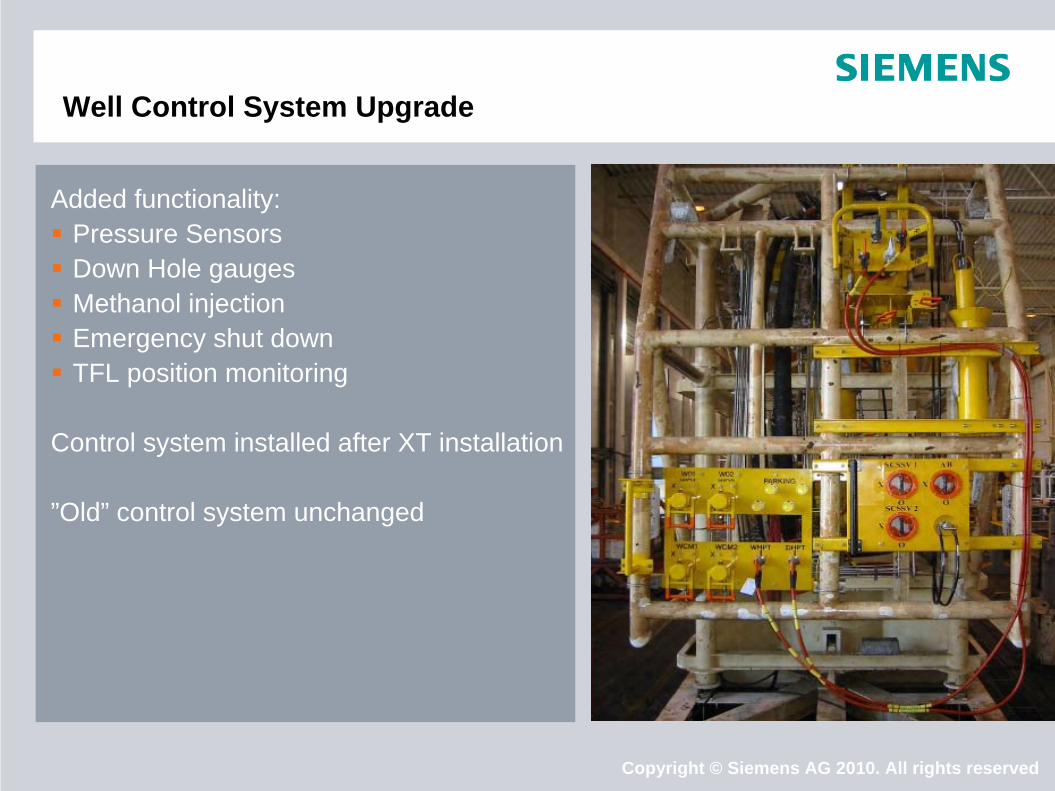
Well Control System Upgrade
Added functionality: Pressure Sensors Down Hole gauges Methanol injection Emergency shut down TFL position monitoring
Control system installed after XT installation
”Old” control system unchanged
Copyright © Siemens AG 2010. All rights reserved
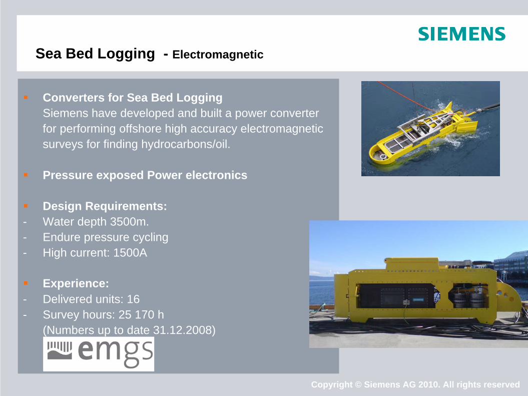
Sea Bed Logging - Electromagnetic
Converters for Sea Bed LoggingSiemens have developed and built a power converter for performing offshore high accuracy electromagnetic surveys for finding hydrocarbons/oil.
Pressure exposed Power electronics
Design Requirements:- Water depth 3500m. - Endure pressure cycling- High current: 1500A
Experience:- Delivered units: 16- Survey hours: 25 170 h
(Numbers up to date 31.12.2008)
Copyright © Siemens AG 2010. All rights reserved
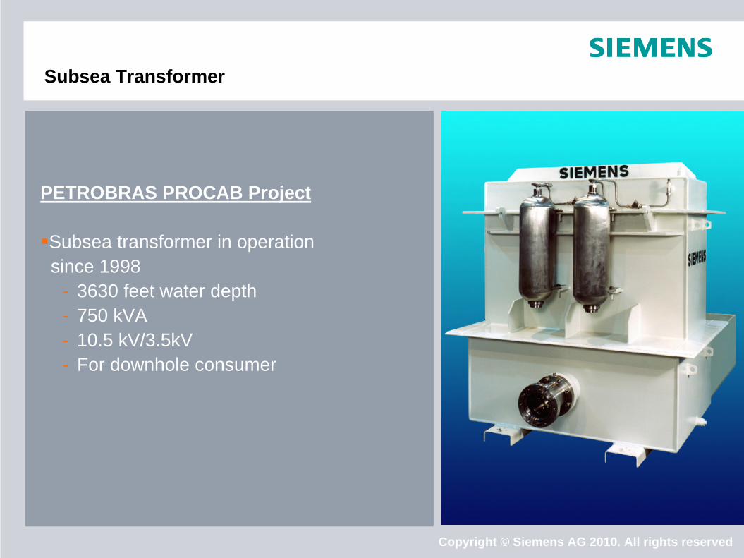
Subsea Transformer
PETROBRAS PROCAB Project
Subsea transformer in operation since 1998
- 3630 feet water depth- 750 kVA- 10.5 kV/3.5kV- For downhole consumer

Copyright © Siemens AG 2010. All rights reserved
Subsea Control References
Client Project Description
ABB Snorre B28 RF-subsea modems for production system communication 2000
Saga/Hydro Snorre B120 subsea control and electrical distribution units for downhole instrumentation (DIACS) 2001
Saga/ Hydro/ StatoilHydro Snorre UPA
15 subsea Well Control Units (WCU/MDU) 2000 - 2009 (Additional instrumentation brown field) From 2006 communication with 3 Mbps powerline modem
Statoil Snorre B 1 subsea Well Control Unit (WCU) 2002
Statoil Snorre B DIACS Field testing 2002/2003
Statoil Snorre UPA Control system feasibility study (WAG project) 2006
StatoilHydro Snorre B Sand monitoring Study 2008
StatoilHydro Snorre BSubsea control system for template C&D Sand monitoring of 16 wells 2009-2010
Statoil Snorre UPAReplacement of 1st generation SEMs -Feasibility Study 2009 (Class B study)
Additionally, Siemens has supplied several Master Control Stations to various projects interfacing all major subsea contractor’s systems.

Copyright © Siemens AG 2010. All rights reserved
We are happy to answer your questions!


![UPDATDED: 1st September, 2014 ... - [Clue & Key]. · PDF fileKey Flashcard Test On-line Practice Lectur es Hand- ... WINNERS' READING & WRITING 1 --Student Book + Workbook O ... (for](https://img.pdfslide.net/doc/110x75/5ab82f287f8b9ab62f8c548b/updatded-1st-september-2014-clue-key-flashcard-test-on-line-practice.jpg)