Embed Size (px)
Citation preview

OTFI-02X0 LED Fiber Illuminator Module Integration Manual 1
OTFI-02X0-17 REV B © Copyright USA 8/19/2014
OTFI-0250
OTFI-0280
OTFI-0290
LED Fiber Illuminator Module
Integration Manual

OTFI-02X0 LED Fiber Illuminator Module Integration Manual 2
OTFI-02X0-17 REV B © Copyright USA 8/19/2014
Thank you for purchasing the OTFI-02X0 LED Fiber Illuminator module. This product is manufactured by Excelitas Technologies, a leader in the design and manufacturer of high performance solid state lighting solutions. To ensure trouble free integration, please read and follow these instructions.
Table of Contents Introduction and Intended Use ..................................................................................2 System Symbol Definitions …………………………………………………………….....3 Safety Warnings and Precautions ……………………………………………….……….3 Product Description …………………………………………………………………….….5 Technical Data …………………………………………………………………………..…5 Optical Specifications ………………………………………………………….………….5 Electrical Specifications …………………………………………………………………..6 EMI Considerations ………………………………………………………….…………….7 Thermal Specifications ………………………………………………………….………...7 Mechanical Specifications and Recommended Mounting Instructions .………….…8 Environmental Specifications ……………………………………………………..……10 Agency Compliance Statement ………………………………………………….….….10 Limited Warranty ……………………………………………………………………….11 Service Contact Information …………………………………………………………….11
Introduction and Intended Use
The Excelitas Technologies OTFI-02X0 LED light source module provides high quality white
light for fiber optic illumination applications. It contains a high brightness LED (light emitting
diode) and associated optics to deliver bright illumination from 400 nm to 700 nm. It is intended
as an alternative to xenon light sources for 1 mm to 6 mm fiber light guides for OEM customer
integration into their medical devices.

OTFI-02X0 LED Fiber Illuminator Module Integration Manual 3
OTFI-02X0-17 REV B © Copyright USA 8/19/2014
System Symbol Description The following table describes the important symbols regarding the safe integration and
operation of the OTFI-02X0 light module. These symbols are located throughout the manual.
Proper care should be taken when these symbols are identified.
Symbol Description
This symbol indicates critical information regarding safe
handling and operation. Serious injury or damage to property
could result if these instructions are not followed.
This symbol contains important information regarding integration and / or operation of the illuminator module.
Safety Warnings and Precautions
WARNING DIRECT VIEWING OF EXITING LIGHT CAN BE HARMFUL
Do not look directly into light output port or connected fiber light guide. The light exiting the light
output port and at the tip of a connected fiber light guide is of high intensity. Always plug the
fiber light guide into the light source before turning on the power and or provide safety interlocks
to cut off power to the LED when a fiber light guide is not present.
LED-based products emit light which, in some circumstances, can cause damage to the eye.
The potential for injury will depend upon many factors including but not limited to:
duration of exposure and extent of pupil dilation prior to exposure;
distance from light source to eye
wavelength of LED light
drive current supplied to LEDs
beam pattern
Buyer must determine the potential for injury and apply all protective measures for safe operation.
NOTE:

OTFI-02X0 LED Fiber Illuminator Module Integration Manual 4
OTFI-02X0-17 REV B © Copyright USA 8/19/2014
WARNING TO PREVENT BURNS
Do not touch the light output port from the light source during or immediately after use to avoid
burns.
Do not touch the light output tip of attached light guides during or immediately after use to avoid
burns.
Use caution when handling fiber light guides that are or have been in contact with the light
source. Although the Fiber Illuminator Module does not emit infrared radiation, the light guide
may become hot from light being absorbed at light output port. The light can be absorbed by
light guides and by materials placed in the optical path causing light energy to be transferred as
heat.
NO USER SERVICEABLE PARTS INSIDE, DO NOT ATTEMPT REPAIRS
In the event the light module should fail please contact Excelitas Technologies for service.
WARNING NEVER DROP OR SUBJECT TO SEVERE IMPACT
Do not drop this equipment or subject it to severe impact as it could compromise the
functionality and / or safety of the unit. Should this equipment be mishandled or dropped do not
use it.
ATTENTION OEM INTEGRATOR LENS CLEANING INSTRUCTIONS
To clean the light source output port, turn off the light source and allow it to cool. Use a soft
lens cloth to gently wipe the glass lens of the light output port. Do not apply force to the lens
when cleaning. It is recommended that the light exit port is not accessible for cleaning by end
users.

OTFI-02X0 LED Fiber Illuminator Module Integration Manual 5
OTFI-02X0-17 REV B © Copyright USA 8/19/2014
Product Description
The light module delivers high-intensity white light from a LED light source. The light module
has an integrated temperature sensor, a heat sink and fan that effectively remove heat
generated by the LED resulting in long life operation. The internal mechanical components are
designed to maintain precise optical alignment of the optical train. The module includes an
aluminum sheet-metal housing with metal fan guards to reduce emissions, and universal
mounting features for simple integration. A terminal block on the back of the unit provides
access to all electrical connections.
OTFI-02X0 Light module U.S. and International
Patents Pending
Technical Data
Optical Specifications
Parameter Units Minimum Typical Maximum
Angle of exit light (FWHM) ° 76
Fiber diameter compatibility mm 1 5 6
Terminal Block
Metal fan guard
Sheet-metal housing
Light output port
NOTE: Light guides should never come into direct contact with the optic in the light output port. It is recommended that there be a 0.1mm gap between the light output port and the mating fiber
NOTE: Remove protective caps from the light output port and light guides before turning the
light module on.

OTFI-02X0 LED Fiber Illuminator Module Integration Manual 6
OTFI-02X0-17 REV B © Copyright USA 8/19/2014
Electrical Specifications
1 LED’s require a constant current power supply which can be operated in either continuous
mode or pulse-width-modulated (PWM) mode. Recommended wire for the LED is16 AWG
stranded wire, UL 1061. 2 Do not exceed maximum voltage. Overvoltage conditions can produce current spikes that will
permanently damage the LED. 3 The OTFI-02X0 Fiber Illuminator Module design was optimized for minimum fan noise in
balance with maximum cooling efficiency. Depending on several parameters including LED
drive current, desired LED life expectancy, and noise baffling, customers may choose to run the
fan at a higher voltage than the minimum 7.0V thereby increasing cooling and decreasing the
LED junction temperature. Recommended wire for the fan is 24 AWG stranded wire, UL 1061. 4 Mounted on a substrate, adjacent to the LED, the thermistor is used to indirectly monitor the
LED temperature. Details on converting resistance measurements to temperature can be found
on the Murata website, www.murata.com. The thermistor part number is Murata
NCP15XH103J03RC. Note the current specified to be run through the thermistor to measure its
resistance is 0.3mA at 10KOhm (25°).
WARNING: REVERSE POLARITY WILL CAUSE DAMAGE TO THE LED.
Observe polarity when connecting the LED anode (+) and LED cathode (-)
Parameter Minimum Typical Maximum
LED current, continuous (A)1 - - 18.0
LED input voltage (Vdc)2 - - 5.4
Fan voltage (Vdc)3 7.0 - 12.0
Fan current draw @ 7.0Vdc (mA)3 - 650 -
Fan current draw @ 12.0Vdc (mA)3 - 840 -
Thermistor resistance @ 25°C (Ohm)4 9,500 10,000 10,500

OTFI-02X0 LED Fiber Illuminator Module Integration Manual 7
OTFI-02X0-17 REV B © Copyright USA 8/19/2014
WARNING: EXCEEDING MAXIMUM VOLTAGE RATING, EVEN
MOMENTARILY, CAN PERMANENTLY DAMAGE THE LED.
EMI Considerations
The OTFI-02X0 has been designed with consideration given to electromagnetic interference
(EMI) concerns. The fiber illuminator module features a sheet metal box enclosure complete
with metal fan guards covering the openings required for fan airflow. To maximize these
attributes, it is recommended to connect the enclosure to ground. Due to high current operation
observe best practices for EMI when connecting the wire/harnesses to the terminal block for the
LED.
Thermal Specifications
In order to maintain the 20,000 hours life expectancy of an LM70 rating (70% of initial output
through 20,000 hours of service), the thermistor temperature must not exceed a maximum of
59°C at a continuous drive current of 18A. This is the most critical thermal consideration and
metric. The OTFI-02X0 can be run at thermistor temperatures higher than 59°C, but with the
effect that useful life will be reduced to less than 20,000 hours.
WARNING: THERMISTOR TEMPERATURE SHOULD NEVER EXCEED 70°C
Regardless of life expectancy, the thermistor temperature should not exceed 70C.
The device must be integrated to ensure sufficient airflow exchange with ambient air to maintain
the recommended thermistor temperatures.
It is recommended that the control electronics include a thermistor temperature monitoring
circuit. It is also recommended that the control electronics provide a warning notification and/or
to shut down the light output when the temperature exceeds pre-determined limits. If
implementing a shut down function, care must be taken to ensure a shut down does not occur
without warning during a critical task.
Direction of airflow for internal fan

OTFI-02X0 LED Fiber Illuminator Module Integration Manual 8
OTFI-02X0-17 REV B © Copyright USA 8/19/2014
Mechanical Specifications and Recommended Mounting Instructions

OTFI-02X0 LED Fiber Illuminator Module Integration Manual 9
OTFI-02X0-17 REV B © Copyright USA 8/19/2014
Pilot flange detail view

OTFI-02X0 LED Fiber Illuminator Module Integration Manual 10
OTFI-02X0-17 REV B © Copyright USA 8/19/2014
For proper alignment to the optical axis of the illuminator, it is recommended to use either the
two M3 metric holes or the two 4-40 standard holes as the pilot feature, as pictured in the front
view. These holes are located central to the mounting holes on the 27mm bolt-hole circle.
In addition to the mounting holes on the front of the device, it is recommended that support be
provided to the module by attaching a bracket to the mounting screw located on the rear side of
the module.
It is also recommended that there be a nominal 0.1mm gap between the light exit port and the
mating fiber to prevent uncured fiber epoxy to transfer to the light guide.
Environmental Specifications
The Product is designed to operate over the following range of environmental conditions:
Ambient Conditions for Operation
Units Min Typical Max
Ambient operating temperature 1 °C 0 20 +40
Relative Humidity % 85
Ambient Conditions for Storage Units Min Typical Max
Storage temperature °C -20 25 +65
Relative Humidity % 85
Note 1: Depending on the customer-determined fan speed, LED life may be reduced at
maximum ambient conditions.
OEM should characterize the OTFI-02X0 in the final design with respect to thermistor
temperature as described in the Thermal Specifications section on page 7.
Agency Compliance Statement
Applicable regulatory requirements
The fiber optic illuminator module complies with the following standard:
Name of standard Number, date of standard
Restriction of Hazardous Substances in Electrical and Electronic Equipment (RoHS)
European Directive 2011/65/EU
Medical electrical equipment - Part 1: General requirements for safety (“2nd Edition”)
IEC 60601-1:1988 +A1:1991 +A2:1995
Medical electrical equipment - Part 1: General requirements for safety and essential performance (“3rd Edition”)
IEC 60601-1:2005 + CORR. 1 (2006) + CORR. 2 (2007)

OTFI-02X0 LED Fiber Illuminator Module Integration Manual 11
OTFI-02X0-17 REV B © Copyright USA 8/19/2014
Limited Warranty Excelitas Technologies warrants the OTFI-02X0 product to be free from defects in material and workmanship and to be in conformance with the written specification for a period of 24 months from date of purchase. If any defect in material or workmanship or failure to conform to such specification is found, the Purchaser should promptly notify Excelitas Technologies. After a Returned Material Authorization number is assigned by Excelitas Technologies, Purchaser may return the product to Excelitas Technologies, carrying charges prepaid. Products will not be accepted for repair, replacement, credit or refund, without the written authorization of and in accordance with Excelitas Technologies instructions. Excelitas Technologies shall analyze the failures, making use, when appropriate of technical information provided by Purchaser relating to the circumstances surrounding the failures. At Excelitas Technologies option, we will repair or replace the product found to be defective, and shall return the product carrying charges prepaid. Excelitas Technologies correction of any defects by the grant of credit, replacement or repair shall constitute fulfillment of all of its obligations and liability to the Purchaser hereunder. Excelitas Technologies is not responsible for damage to its product caused by misuse, neglect, accident, shipping, abuse, maintenance, cleaning procedures, use or attempts to operate above its rated capacity intentionally or that otherwise deviate from the parameters established in the user integration manual and applicable specifications; or to products that have been improperly installed, stored, maintained, repaired or altered by anyone other than Excelitas Technologies; or have had their serial numbers or month and year of manufacture or shipment removed, defected or altered. Any actions cited above shall terminate this Warranty and shall relieve Excelitas Technologies from any further responsibility. Excelitas Technologies shall not be liable for any incidental, special, or consequential damages in any claim action, suit or proceeding arising under this Warranty or any other part of the agreement of sale between Excelitas Technologies and the Purchaser, nor shall there be any liability hereunder for claims for labor, loss of profits or good will, repairs or other expenses incidental to replacement. This warranty does not extend to any system into which a product is incorporated. No other warranty, including warranties of merchantability or fitness for a particular purpose is given with respect to such service or any other service provided by Excelitas Technologies under this Agreement. This warranty applies only to Purchaser and may not be assigned or extended by Purchaser to any of its customers or other users of the Items. Excelitas Technologies will not accept any returns from Purchaser's customers or users of Purchaser's products. Product specifications are subject to change without notice.
Service Contact Information For service please contact: Excelitas Technologies Corp 160 E. Marquardt Drive Wheeling, IL 60090 USA T: (847) 537- 4277 F: (847) 537- 4785 www.Excelitas.com
OTFI-02X0 LED Fiber Illuminator Module Integration Manual 12
OTFI-02X0-17 REV B © Copyright USA 8/19/2014
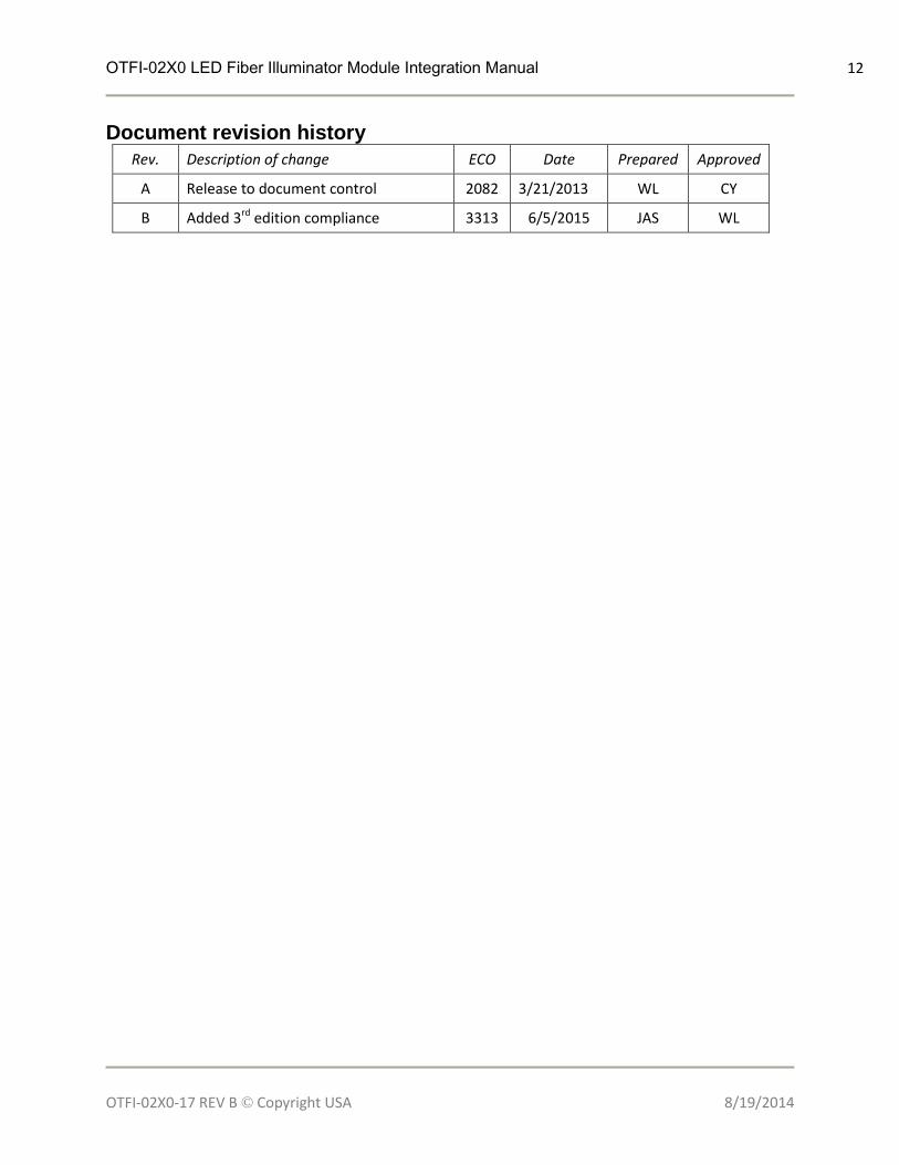
Document revision history
Rev. Description of change ECO Date Prepared Approved
A Release to document control 2082 3/21/2013 WL CY
B Added 3rd edition compliance 3313 6/5/2015 JAS WL