Embed Size (px)
Citation preview

1
Cornerstone Electronics Technology and Robotics I Week 12 Other Sources of Electrical Energy and Photoresistors
Administration: o Prayer o Turn in quiz
Review the six basic sources of electricity or electromotive force: o Friction (covered in Week 1, Statics) o Chemical Action (covered in Week 10, Batteries) o Light (this week’s lesson) o Heat (this week’s lesson) o Pressure (this week’s lesson) o Magnetism (covered in Week 17)
Electricity and Electronics, Section 5.2, Other Sources of Electrical Energy: o Electrical Energy from Light:
Two forms of solar energy conversion: Solar thermal, that is, thermal systems (hot water, pool heaters)
produce heat from the sun’s radiation at 40% efficiency. Photovoltaic (photo = light; voltaic = produces voltage) systems
convert light directly into electricity using semiconductor technology at about 10% efficiency.
As long as there is light flowing into the cells, there are electrons flowing out of the cells. The cells do not “use up its electrons and loose power, like a battery. It is just a converter, changing one kind of energy (sunlight) into another (flowing electrons or electrical). For every electron that flows out of the wire connected to the front of a cell, there is another electron flowing into the back from the other wire.
Demonstrate using a 10 watt solar panel. Each cell only produces about ½ volt, and a module
usually needs to charge a 12 volt battery or to run motors. A typical module has 36 cells connected in series to increase the voltage. 36 times ½ volt equals 18 volts. However, the voltage is reduced as the cells get hot in the sun and 12 volt batteries typically need about 14 volts for a charge, so the 36 cell module has become the standard for the solar battery charger industry.

2
o Types of Photovoltaic Systems: Systems for Day Direct Current (DC) Use:
Day Use
System for Cloudy Weather and Night DC Use:
DC System with Storage Battery
System for Cloudy Weather and Night DC and AC Use:
DC and AC System
3
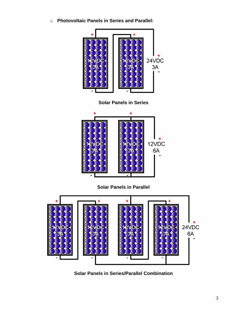
o Photovoltaic Panels in Series and Parallel:
Solar Panels in Series
Solar Panels in Parallel
Solar Panels in Series/Parallel Combination

4
o Photoelectric Control: Photoresistors are used for photoelectric control by controlling current. They are not a source of electrical energy. Also called Cds photocells or simply photocells. Photoresistors change their resistance in response to the amount of
light shining on them. The more light striking a photocell, the lower its resistance. Samples:
Photoresistor or Cds Photocell Assortment of Photoresistors Useful for light seeking (photovore) robots, color sensors, and also as
an optical switch: Photovore robot video:
http://www.youtube.com/watch?v=N_X4_VVxOrE Color sensors reference:
http://www.societyofrobots.com/sensors_color.shtml Optical switch: Perform Other Electrical Sources and
Photoresistors Lab 1 - Photoresistors Perform Other Electrical Sources and Photoresistors Lab 2 –
Balanced Brightness Circuit o Electrical Energy from Heat:
Thermocouple When two dissimilar metals in contact with each other are
heated, a potential difference (voltage) develops between the metals.
Applications: o Demonstrate K-type thermocouple thermometers
(Taylor and Metex) o Temperature probe in an industrial furnace o Pilot light safety valve
Perform Other Electrical Sources and Photoresistors Lab 3 – Thermocouples

5
o Electrical Energy from Mechanical Pressure Piezoelectric effect: Creating a potential difference (voltage) from the
mechanical distortion of a crystal. Applications:
Crystal microphone Phonograph needle pickup Engine knock sensor
Demonstrate piezoelectric cell (WINSCO Part # GS-711, see: http://www.winsco.com/products/genscience.htm)
Fuel Cell: A fuel cell is an electrochemical device that combines
hydrogen and oxygen to produce electricity, with water and heat as its by-product.
As long as fuel is supplied, the fuel cell will continue to generate power.
Since the conversion of the fuel to energy takes place via an electrochemical process, not combustion, the process is clean, quiet and highly efficient – two to three times more efficient than fuel burning.
Efficiency, theoretically 100% Applications: See: http://www.fuelcells.org/basics/apps.html Demonstration using H2 fuel cell car
Electricity from Magnetism Generators convert rotating mechanical energy into electrical
energy through magnetism. Demonstrate handheld generator. Covered in more detail in Week 17.
o Related web sites: http://www.allaboutcircuits.com/vol_1/chpt_11/4.html http://alternative-energy-search-engine-swicki.eurekster.com/ http://www.freesunpower.com/solar_simulator.php http://www.societyofrobots.com/schematics_photoresistor.shtml
6
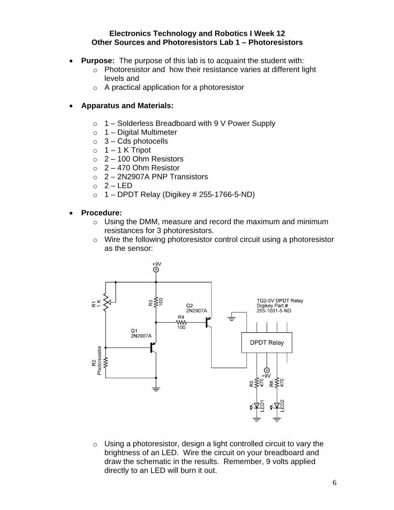
Electronics Technology and Robotics I Week 12 Other Sources and Photoresistors Lab 1 – Photoresistors
Purpose: The purpose of this lab is to acquaint the student with:
o Photoresistor and how their resistance varies at different light levels and
o A practical application for a photoresistor Apparatus and Materials:
o 1 – Solderless Breadboard with 9 V Power Supply o 1 – Digital Multimeter o 3 – Cds photocells o 1 – 1 K Tripot o 2 – 100 Ohm Resistors o 2 – 470 Ohm Resistor o 2 – 2N2907A PNP Transistors o 2 – LED o 1 – DPDT Relay (Digikey # 255-1766-5-ND)
Procedure:
o Using the DMM, measure and record the maximum and minimum resistances for 3 photoresistors.
o Wire the following photoresistor control circuit using a photoresistor as the sensor:
o Using a photoresistor, design a light controlled circuit to vary the
brightness of an LED. Wire the circuit on your breadboard and draw the schematic in the results. Remember, 9 volts applied directly to an LED will burn it out.

7
Results: o Cds Photocell Resistances:
Design Challenge: o Using a photoresistor, design a light controlled circuit to vary the
brightness of an LED. Wire the circuit on your breadboard and draw the schematic in the results. Remember, 9 volts applied directly to an LED will burn it out.
o Using the circuit on page 18 and two dc motors instead of the resistors and LEDs design and build a robotic car whose motion direction can be controlled using a flashlight. Tape the motors to the car.

8
Electronics Technology and Robotics I Week 12 Other Sources and Photoresistors Lab 2 – Balanced Brightness Circuit
Purpose: The purpose of this lab is to acquaint the student with the operation of the “Sandwich” sensor circuit.
Apparatus and Materials:
o 1 – Solderless Breadboard with 9 V Power Supply o 1 – Digital Multimeter o 1 – 150 Ohm Resistor o 1 – 20K Tripot o 4 – Photoresistors Jameco #120299 (See:
http://www.jameco.com/webapp/wcs/stores/servlet/ProductDisplay?langId=-1&productId=120299&catalogId=10001&freeText=120299&app.products.maxperpage=15&storeId=10001&search_type=jamecoall&ddkey=http:StoreCatalogDrillDownView
Procedure: o Photoresistors are aligned in pairs so it can detect a wider area
than a single photoresistor. o Build the following balanced brightness-sensing circuit that will be
used as the sensing circuit for Sandwich, the line following robot.
Balanced Brightness Circuit Schematic and Layout

9
o Measure the voltages at Test Points 1 and 2. o Using ambient lighting, adjust R2 to equalize the voltages at Test
Points 1 and 2. Ambient means of the surrounding area or environment.
o Now take a flashlight and shine it over each pair of photocells and measure the voltage differential between Test Points 1 and 2. Shield the other pair of photocells from the flashlight.
o The variation of the voltage at the test points will be critical for Sandwich to follow a line.
Results:
Conclusions: o What is the purpose of the 470 ohm resistor?

10
Electronics Technology and Robotics I Week 12 Other Sources and Photoresistors Lab 3 – Thermocouples
Purpose: The purpose of this lab is to acquaint the student with the basic
construction of a thermocouple. Apparatus and Materials:
o 1 – Digital Multimeter o 1 – Piece of Copper Wire o 1 – Piece of Steel Wire o 1 – Pair of Pliers o 1 – Match or Gas Lighter
Procedure: o Twist the copper and steel wires together. o Connect the multimeter leads to the two twisted wires. Hold the
steel wire as shown to protect the positive multimeter lead. o Measure and record the voltage before heat is applied. o Apply the flame to the far end of the twisted wires to protect the
negative multimeter lead. Record the voltage output of this thermocouple as heat is applied and after cool down.
Results: