Embed Size (px)
Citation preview
OTS-RSU-1
Optiva Redundancy Switch Unit (RSU) Installation Manual
MAN-OPTIVA-RSU, Rev A
Emcore Corporation OTS-RSU series
Copyright © 2010 Emcore Corporation MAN-OPTIVA-RSU, Rev A
Page 2 of 12
Table of Contents General ................................................................................................................................................3
Optiva RSU / Fiberoptic Transmission System ........................................................................................3 Interface and Controls ..............................................................................................................................5 Redundancy Switch Unit (RSU) ...............................................................................................................5
Installation ......................................................................................................................................6
Operation..........................................................................................................................................6 Control Modes..........................................................................................................................................6 Manual Control Mode ..............................................................................................................................6 Automatic Control Mode..........................................................................................................................6 RSU Summary Status ...............................................................................................................................7 RSU LED Indicators.................................................................................................................................8 DIP Switches ............................................................................................................................................8
Remote Monitoring.............................................................................................................8 Simple Network Management Protocol (SNMP) .....................................................................................8
Specifications ...............................................................................................................................9
Ordering Information ...................................................................................................10
Disclaimer ......................................................................................................................................10
Optics Handling & Safety ........................................................................................10
Warranty ........................................................................................................................................12
EMCORE Corporation offers a broad portfolio of compound semiconductor-based components and systems for the broadband, fiber optic, satellite communication, defense and solar power markets. EMCORE has two primary operating segments: Fiber Optics and Photovoltaics. The company’s integrated solutions philosophy embodies state-of-the-art technology, material science expertise, and a shared vision of our customer’s goals and objectives to be leaders in fiber optics and photovoltaics. EMCORE’s solutions include: optical components and subsystems for fiber-to-the-premise, cable television, high speed data and telecommunication networks; defense photonics products for commercial and military applications including lasers, modulators, spectrometers, sensors, fiber gyro components and diagnostic instruments; solar cells, solar panels, and fiber optic ground station links for global satellite communications.
2015 Chestnut Street Alhambra, California 91803, USA (626) 293-3400 Fax: (626)293-3428 www.emcore.com
Emcore Corporation OTS-RSU series
Copyright © 2010 Emcore Corporation MAN-OPTIVA-RSU, Rev A
Page 3 of 12
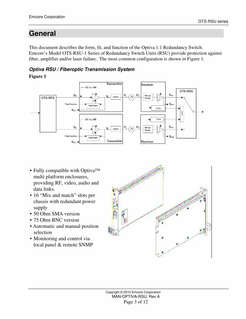
General This document describes the form, fit, and function of the Optiva 1:1 Redundancy Switch. Emcore’s Model OTS-RSU-1 Series of Redundancy Switch Units (RSU) provide protection against fiber, amplifier and/or laser failure. The most common configuration is shown in Figure 1.
Optiva RSU / Fiberoptic Transmission System Figure 1
• Fully compatible with Optiva™ multi platform enclosures, providing RF, video, audio and data links.
• 16 “Mix and match” slots per chassis with redundant power supply
• 50 Ohm SMA version • 75 Ohm BNC version • Automatic and manual position
selection • Monitoring and control via
local panel & remote SNMP
Emcore Corporation OTS-RSU series
Copyright © 2010 Emcore Corporation MAN-OPTIVA-RSU, Rev A
Page 4 of 12
Optiva™ L-band fiber optic intra-facility links are a high-performance, cost-effective alternative to coaxial cable. They provide much longer transmission distances than copper cables, which simplify network design, ease installation and even enhance immunity from EMI, RFI and lightning. These transmitters and receivers take the best RF design features of Emcore’s extensive families of products and combine them into a compact package compatible with the Optiva™ OT-CC-16 chassis. The Optiva™ family’s wide range of RF, video, audio and data transport products include a unique data bus design that provides a higher level of monitoring and control with a single chassis mix and match flexibility. The final result is a chassis system that can be factory or user custom configured to meet a wide range of fiber transport applications. All units come as an insert card version. The cards can be inserted into the Optiva 3RU 16-slot, 19” rack-mountable card cage (OT-CC-16), 1RU 4-slot 19” rack (OT-CC-4-1U) or one of the smaller Optiva™ Desktop Card Racks (OT-DTCR Series). The power supply must be the 12-volt version.
Emcore Corporation OTS-RSU series
Copyright © 2010 Emcore Corporation MAN-OPTIVA-RSU, Rev A
Page 5 of 12
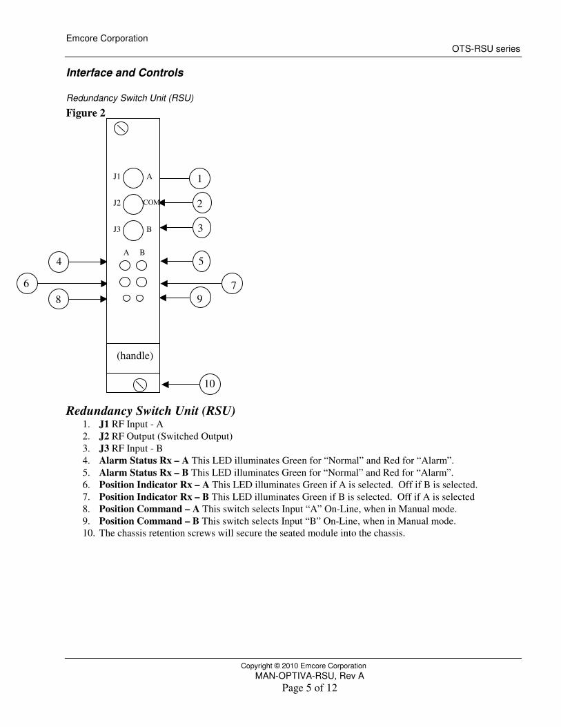
Interface and Controls
Redundancy Switch Unit (RSU)
Figure 2
Redundancy Switch Unit (RSU) 1. J1 RF Input - A 2. J2 RF Output (Switched Output) 3. J3 RF Input - B 4. Alarm Status Rx – A This LED illuminates Green for “Normal” and Red for “Alarm”. 5. Alarm Status Rx – B This LED illuminates Green for “Normal” and Red for “Alarm”. 6. Position Indicator Rx – A This LED illuminates Green if A is selected. Off if B is selected. 7. Position Indicator Rx – B This LED illuminates Green if B is selected. Off if A is selected 8. Position Command – A This switch selects Input “A” On-Line, when in Manual mode. 9. Position Command – B This switch selects Input “B” On-Line, when in Manual mode. 10. The chassis retention screws will secure the seated module into the chassis.
1
2
3
4
7\
68 9
(handle)
A B
J1
J2
J3
A
B
COM
10
5
Emcore Corporation OTS-RSU series
Copyright © 2010 Emcore Corporation MAN-OPTIVA-RSU, Rev A
Page 6 of 12
Installation RSU Installation
• Align the top and bottom card edges in the chassis channel and slide firmly into the back plane.
• Tighten the top and bottom module screws to secure in chassis. • Connect cables to J1 and J3. • With both the RSU and Rx units installed connect the input RF connectors. Refer to Figures
1 and 2. • In order to facilitate automatic switching the receiver’s optical status LED must be
illuminated Green. • Connect the RF Out of the Rx “A” to J1 of the RSU and the RF Out of the Rx “B” to J3 of
the RSU. Refer to Figure 2.
Operation
Control Modes The Redundancy Switch Unit is an electronically controlled single-pole double-throw RF switch with a frequency response from DC to 18 GHz. The front panel of the Redundancy Switch Unit is shown in Figure 1. The RSU can be toggled between two primary control modes of Manual and Auto by either of the following methods:
• Momentarily pushing the appropriate Position Command button on the front Panel of the RSU. (Selection of Auto / Manual is accomplished by S1-5 on the main DC control PCBA. Unit is shipped from the factory in the Auto state, S1-5 ON.)
• Remotely commanding the unit via SNMP. When toggling control modes, the RSU maintains its most recent switch position. When switching into Auto, certain alarm conditions may cause the switch to change position.
NOTE: A toothpick or cotton swab end provides a convenient, safe way to access the recessed buttons and switches. For a toothpick, break off the end for a flatter surface.
Manual Control Mode When in Manual Mode, the user sets the switch position by either: • Momentarily pushing one of the two Position buttons on the Interface Panel. • Remotely commanding the unit via SNMP.
Automatic Control Mode In Auto Mode, the RF Switch toggles to either Position A or B according to the two external inputs A Status and B Status that come from the rear connector of the RSU. (See Table 1 below.)
Emcore Corporation OTS-RSU series
Copyright © 2010 Emcore Corporation MAN-OPTIVA-RSU, Rev A
Page 7 of 12
Table 1 Alarm Switching Conditions
A or B Status Meaning Input Physical Characteristics
1 OK TTL High 0 FAIL TTL Low or Open
In the Auto Mode, the internal electronics keep the RF switch in its present position as long as no alarm is present. If an alarm is detected the RSU will toggle to the other position, provided that the other link is good. If however the other link also is bad, then the switch stays in its present position. If both are bad and either one of the failed links is restored, the switch toggles to whichever link is restored first. (See Table 2 below.)
Table 2 Redundancy Switch Unit Auto Mode Switching Conditions
Initial Position
A Status
B Status
Final Position
A 1 0 or 1 A (No change) A 0 1 B A 0 or 1 0 A (No change)
B 0 or 1 1 B (No change) B 1 0 A B 0 0 or 1 B (No change)
RSU Summary Status The following Summary Alarm information for the RSU is communicated to the NMS card on the backplane. (See Tables 3, 4, 5 and 6 below.)
Table 3 Alarm Conditions Report to NMS General Definition RSU Conditions That Are Represented. OK Alarm Major failure condition. • Auto Mode and the active link is Fail.
• Catastrophic failure or loss of power of RSU itself.
Emcore Corporation OTS-RSU series
Copyright © 2010 Emcore Corporation MAN-OPTIVA-RSU, Rev A
Page 8 of 12
RSU LED Indicators Table 4 Status LEDs
Color A Status Color B Status Green 1 Green 1 Red 0 Red 0
Table 5 Position LEDs
Switch Position
Position A LED
Position B LED
A Green OFF B OFF Green
DIP Switches The following DIP Switch table is provided for reference. The RSU is supplied with all switches in the “Off” position, which is the normal configuration. (See Table 6 below.)
Table 6 DIP Switch settings
# “ON” Side Silkscreen on Board
NOTES Default when shipped, unless noted otherwise.
1 A Backplane If ON, then “A” Status determined by Backplane input. ON 2 B Backplane If ON, then “B” Status determined by Backplane input. ON 3 Spare OFF 4 Spare OFF 5 Auto / Man If ON, then “Auto” , if OFF “Man” ON 6 Spare OFF 7 Spare OFF 8 Spare OFF 9 Spare OFF
10 Spare OFF
Remote Monitoring
Simple Network Management Protocol (SNMP) The Optiva System is designed to provide remote status and control monitoring via SNMP monitoring programs. Use of this feature requires the use of a network management system controller card (NMS) that serves as the interface between the data retrieved from the system cards and the management program. Management Interface Bases (MIB’s) are available with the purchase of the NMS card (OPV-CTLR-IC). The MIB defines the detailed variables and protocol for the particular product. (See Table 8 below.)
Emcore Corporation OTS-RSU series
Copyright © 2010 Emcore Corporation MAN-OPTIVA-RSU, Rev A
Page 9 of 12
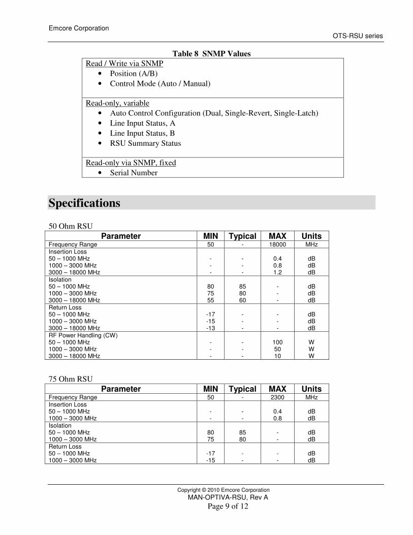
Table 8 SNMP Values Read / Write via SNMP
• Position (A/B) • Control Mode (Auto / Manual)
Read-only, variable
• Auto Control Configuration (Dual, Single-Revert, Single-Latch) • Line Input Status, A • Line Input Status, B • RSU Summary Status
Read-only via SNMP, fixed
• Serial Number
Specifications 50 Ohm RSU
Parameter MIN Typical MAX Units Frequency Range 50 - 18000 MHz Insertion Loss 50 – 1000 MHz 1000 – 3000 MHz 3000 – 18000 MHz
- - -
- - -
0.4 0.8 1.2
dB dB dB
Isolation 50 – 1000 MHz 1000 – 3000 MHz 3000 – 18000 MHz
80 75 55
85 80 60
- - -
dB dB dB
Return Loss 50 – 1000 MHz 1000 – 3000 MHz 3000 – 18000 MHz
-17 -15 -13
- - -
- - -
dB dB dB
RF Power Handling (CW) 50 – 1000 MHz 1000 – 3000 MHz 3000 – 18000 MHz
- - -
- - -
100 50 10
W W W
75 Ohm RSU
Parameter MIN Typical MAX Units Frequency Range 50 - 2300 MHz Insertion Loss 50 – 1000 MHz 1000 – 3000 MHz
- -
- -
0.4 0.8
dB dB
Isolation 50 – 1000 MHz 1000 – 3000 MHz
80 75
85 80
- -
dB dB
Return Loss 50 – 1000 MHz 1000 – 3000 MHz
-17 -15
- -
- -
dB dB
Emcore Corporation OTS-RSU series
Copyright © 2010 Emcore Corporation MAN-OPTIVA-RSU, Rev A
Page 10 of 12
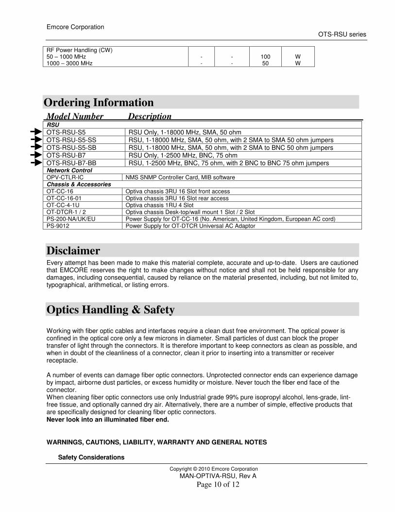
RF Power Handling (CW) 50 – 1000 MHz 1000 – 3000 MHz
- -
- -
100 50
W W
Ordering Information Model Number Description RSU OTS-RSU-S5 RSU Only, 1-18000 MHz, SMA, 50 ohm OTS-RSU-S5-SS RSU, 1-18000 MHz, SMA, 50 ohm, with 2 SMA to SMA 50 ohm jumpers OTS-RSU-S5-SB RSU, 1-18000 MHz, SMA, 50 ohm, with 2 SMA to BNC 50 ohm jumpers OTS-RSU-B7 RSU Only, 1-2500 MHz, BNC, 75 ohm OTS-RSU-B7-BB RSU, 1-2500 MHz, BNC, 75 ohm, with 2 BNC to BNC 75 ohm jumpers Network Control OPV-CTLR-IC NMS SNMP Controller Card, MIB software Chassis & Accessories OT-CC-16 Optiva chassis 3RU 16 Slot front access OT-CC-16-01 Optiva chassis 3RU 16 Slot rear access OT-CC-4-1U Optiva chassis 1RU 4 Slot OT-DTCR-1 / 2 Optiva chassis Desk-top/wall mount 1 Slot / 2 Slot PS-200-NA/UK/EU Power Supply for OT-CC-16 (No. American, United Kingdom, European AC cord) PS-9012 Power Supply for OT-DTCR Universal AC Adaptor
Disclaimer Every attempt has been made to make this material complete, accurate and up-to-date. Users are cautioned that EMCORE reserves the right to make changes without notice and shall not be held responsible for any damages, including consequential, caused by reliance on the material presented, including, but not limited to, typographical, arithmetical, or listing errors.
Optics Handling & Safety Working with fiber optic cables and interfaces require a clean dust free environment. The optical power is confined in the optical core only a few microns in diameter. Small particles of dust can block the proper transfer of light through the connectors. It is therefore important to keep connectors as clean as possible, and when in doubt of the cleanliness of a connector, clean it prior to inserting into a transmitter or receiver receptacle. A number of events can damage fiber optic connectors. Unprotected connector ends can experience damage by impact, airborne dust particles, or excess humidity or moisture. Never touch the fiber end face of the connector. When cleaning fiber optic connectors use only Industrial grade 99% pure isopropyl alcohol, lens-grade, lint-free tissue, and optionally canned dry air. Alternatively, there are a number of simple, effective products that are specifically designed for cleaning fiber optic connectors. Never look into an illuminated fiber end. WARNINGS, CAUTIONS, LIABILITY, WARRANTY AND GENERAL NOTES
Safety Considerations
Emcore Corporation OTS-RSU series
Copyright © 2010 Emcore Corporation MAN-OPTIVA-RSU, Rev A
Page 11 of 12
When installing or using this product, observe all safety precautions during handling and operation. Refer to the manual and / or data sheet for the optical transmitter for the precautions appropriate to the power and wavelength of that device. Failure to comply with the following general safety precautions and with specific precautions described elsewhere in the manual violates the safety standards of the design, manufacture, and intended use of this product. Emcore assumes no liability for the customer's failure to comply with these precautions.
Electrostatic Sensitivity
Observe electrostatic precautionary procedures. Semiconductor laser transmitters and receivers provide highly reliable performance when operated in conformity with their intended design. However, a semiconductor laser may be damaged by an electrostatic charge inadvertently imposed by careless handling. Static electricity can be conducted to the laser chip from the center pin of the RF input connector, and through the DC connector pins. When unpacking and otherwise handling the transmitter, follow ESD precautionary procedures including use of grounded wrist straps, grounded workbench surfaces, and grounded floor mats. Exposure to electrostatic charge is greatly reduced after the transmitter or receiver has been installed in an operational circuit. Service
Do not attempt to modify or service any part of the system other than in accordance with procedures outlined in this Operation Manual. If the system does not meet its warranted specifications, or if a problem is encountered that requires service, return the apparently faulty plug-in or assembly to Emcore for evaluation in accordance with Emcore's warranty policy. When returning a plug-in or assembly for service, include the following information: Owner, Model Number, Serial Number, Return Authorization Number (obtained in advance from Emcore's Customer Service Dept.), service required and/or description of the problem encountered.
Emcore Corporation OTS-RSU series
Copyright © 2010 Emcore Corporation MAN-OPTIVA-RSU, Rev A
Page 12 of 12
Warranty Emcore warrants to the original purchaser all standard products sold by Emcore to be free of defects in material and workmanship for three (3) years from date of shipment from Emcore. During the warranty period, Emcore's obligation, at our option, is limited to repair or replacement of any product that Emcore proves to be defective. This warranty does not apply to any product that has been subject to alteration, abuse, improper installation or application, accident, electrical or environmental over-stress, negligence in use, storage, transportation, or handling.
This warranty is the only warranty made by Emcore and is in lieu of all other warranties, expressed or implied, except as to title, and can be amended only by a written instrument signed by an officer of Emcore. Emcore sales agents or representatives are not authorized to make commitments on warranty returns. Limitations of Liabilities Emcore's liability on any claim of any kind, including negligence, for any loss or damage arising from, connected with, or resulting from the purchase order, contract, or quotation, or from the performance or breach thereof, or from the design, manufacture, sale, delivery, installation, inspection, operation or use of any equipment covered by or furnished under this contract, shall in no case exceed the purchase price of the device which gives rise to the claim.
EXCEPT AS EXPRESSLY PROVIDED HEREIN, EMCORE MAKES NO WARRANTY OF ANY KIND, EXPRESSED OR IMPLIED, WITH RESPECT TO ANY GOODS, PARTS AND SERVICES PROVIDED IN CONNECTION WITH THIS AGREEMENT INCLUDING, BUT NOT LIMITED TO, THE IMPLIED WARRANTIES OF MERCHANTABILITY AND FITNESS FOR A PARTICULAR PURPOSE. EMCORE SHALL NOT BE LIABLE FOR ANY OTHER DAMAGE INCLUDING, BUT NOT LIMITED TO, INDIRECT, SPECIAL OR CONSEQUENTIAL DAMAGES ARISING OUT OF OR IN CONNECTION WITH FURNISHING OF GOODS, PARTS AND SERVICE HEREUNDER, OR THE PERFORMANCE, USE OF, OR INABILITY TO USE THE GOODS, PARTS AND SERVICE. Emcore will not be responsible for loss of output or reduced output of opto-electronic devices if the customer performs chip mounting, ribbon bonding, wire bonding, fiber coupling, fiber connectorization, or similar operations. These processes are critical and may damage the device or may affect the device's output or the fiber output. Emcore test reports or data indicating mean-time-to-failure, mean-time-between-failure, or other reliability data are design guides and are not intended to imply that individual products or samples of products will achieve the same results. These numbers are to be used as management and engineering tools, and are not necessarily indicative of expected field operation. These numbers assume a mature design, good parts, and no degradation of reliability due to manufacturing procedures and processes. Emcore is not liable for normal laser output degradation or fiber coupling efficiency degradation over the life of the device. Every attempt has been made to make this material as complete and accurate and up to date. Users are cautioned that Emcore reserves the right to make changes without notice and shall not be held responsible for any damages, including consequential, caused by reliance on the material presented, including, but not limited to, typographical, arithmetical, or listing errors. Copyright 2010 EMCORE Corporation