Embed Size (px)
Citation preview
Out-of-Band Radiation fromLarge Antenna Arrays
Christopher Mollen, Erik G. Larsson, Ulf Gustavsson,Thomas Eriksson and Robert W. Heath, Jr.
April 6, 2017
Abstract
Co-existing wireless systems, which share a common spectrum, need to mitigateout-of-band (OOB) radiation to avoid excessive interference. For legacy systems,OOB radiation is well understood and is commonly handled by digital precompensa-tion techniques. When using large arrays, however, new phenomena and hardwarelimitations have to be considered. First, signals can be radiated directionally, whichmight focus the OOB radiation. Second, low-complexity hardware is used for costreasons, which increases the relative amount of OOB radiation. Given that massiveMIMO and millimeter wave communication rely on base stations with a large num-ber of antennas, the spatial behavior of OOB radiation from large arrays will havesignificant implications for the hardware requirements of future base stations. Weshow that, if the OOB radiation is beamformed, its array gain is never larger thanthat of the in-band signal. In many cases, the OOB radiation is close to isotropiceven when the in-band signal is highly directive. With the same total radiatedpower, the OOB radiation from large arrays is therefore never more severe than froma legacy system with the same adjacent-channel-leakage ratio. Further, the OOB
radiation is less detrimental than from a legacy system since the high array gain ofthe in-band signal allows large arrays to radiate less total power than legacy systems.We also show how OOB radiation from large arrays varies with location in staticpropagation environments and how these effects vanish when averaged over thesmall-scale fading. Since a higher relative amount of OOB radiation can be toleratedfor large arrays, the linearity requirement can be relaxed as compared to legacy sys-tems. Specifically, less stringent linearity requirements on each transmitter makes itpossible to build large arrays from low-complexity hardware.
This work has been submitted to the IEEE for possible publication. Copyright may be transferredwithout notice, after which this version may no longer be accessible.
arX
iv:1
611.
0135
9v2
[cs
.IT
] 5
Apr
201
7
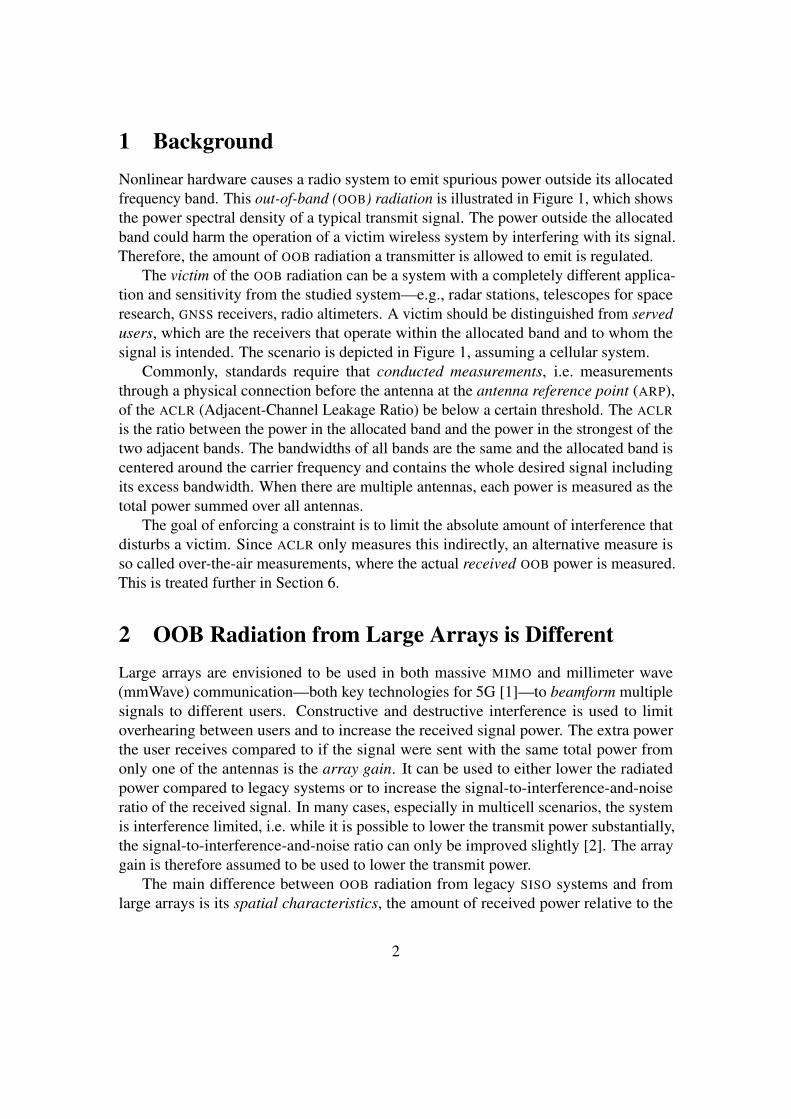
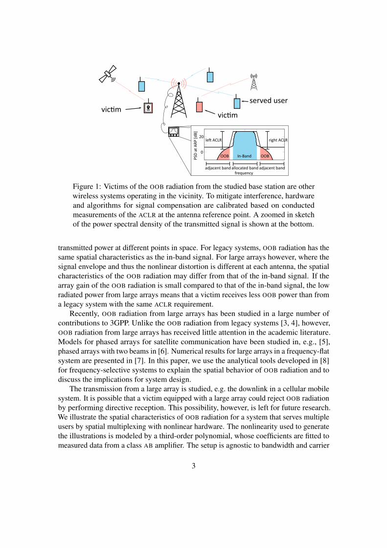
1 BackgroundNonlinear hardware causes a radio system to emit spurious power outside its allocatedfrequency band. This out-of-band (OOB) radiation is illustrated in Figure 1, which showsthe power spectral density of a typical transmit signal. The power outside the allocatedband could harm the operation of a victim wireless system by interfering with its signal.Therefore, the amount of OOB radiation a transmitter is allowed to emit is regulated.
The victim of the OOB radiation can be a system with a completely different applica-tion and sensitivity from the studied system—e.g., radar stations, telescopes for spaceresearch, GNSS receivers, radio altimeters. A victim should be distinguished from servedusers, which are the receivers that operate within the allocated band and to whom thesignal is intended. The scenario is depicted in Figure 1, assuming a cellular system.
Commonly, standards require that conducted measurements, i.e. measurementsthrough a physical connection before the antenna at the antenna reference point (ARP),of the ACLR (Adjacent-Channel Leakage Ratio) be below a certain threshold. The ACLR
is the ratio between the power in the allocated band and the power in the strongest of thetwo adjacent bands. The bandwidths of all bands are the same and the allocated band iscentered around the carrier frequency and contains the whole desired signal includingits excess bandwidth. When there are multiple antennas, each power is measured as thetotal power summed over all antennas.
The goal of enforcing a constraint is to limit the absolute amount of interference thatdisturbs a victim. Since ACLR only measures this indirectly, an alternative measure isso called over-the-air measurements, where the actual received OOB power is measured.This is treated further in Section 6.
2 OOB Radiation from Large Arrays is DifferentLarge arrays are envisioned to be used in both massive MIMO and millimeter wave(mmWave) communication—both key technologies for 5G [1]—to beamform multiplesignals to different users. Constructive and destructive interference is used to limitoverhearing between users and to increase the received signal power. The extra powerthe user receives compared to if the signal were sent with the same total power fromonly one of the antennas is the array gain. It can be used to either lower the radiatedpower compared to legacy systems or to increase the signal-to-interference-and-noiseratio of the received signal. In many cases, especially in multicell scenarios, the systemis interference limited, i.e. while it is possible to lower the transmit power substantially,the signal-to-interference-and-noise ratio can only be improved slightly [2]. The arraygain is therefore assumed to be used to lower the transmit power.
The main difference between OOB radiation from legacy SISO systems and fromlarge arrays is its spatial characteristics, the amount of received power relative to the
2
vic�m
served uservic�m
allocated band
OOB In-Band
frequency
PSD
at
AR
P [
dB
]
OOB
adjacent bandadjacent band
right ACLRle� ACLR
0
20
Figure 1: Victims of the OOB radiation from the studied base station are otherwireless systems operating in the vicinity. To mitigate interference, hardwareand algorithms for signal compensation are calibrated based on conductedmeasurements of the ACLR at the antenna reference point. A zoomed in sketchof the power spectral density of the transmitted signal is shown at the bottom.
transmitted power at different points in space. For legacy systems, OOB radiation has thesame spatial characteristics as the in-band signal. For large arrays however, where thesignal envelope and thus the nonlinear distortion is different at each antenna, the spatialcharacteristics of the OOB radiation may differ from that of the in-band signal. If thearray gain of the OOB radiation is small compared to that of the in-band signal, the lowradiated power from large arrays means that a victim receives less OOB power than froma legacy system with the same ACLR requirement.
Recently, OOB radiation from large arrays has been studied in a large number ofcontributions to 3GPP. Unlike the OOB radiation from legacy systems [3, 4], however,OOB radiation from large arrays has received little attention in the academic literature.Models for phased arrays for satellite communication have been studied in, e.g., [5],phased arrays with two beams in [6]. Numerical results for large arrays in a frequency-flatsystem are presented in [7]. In this paper, we use the analytical tools developed in [8]for frequency-selective systems to explain the spatial behavior of OOB radiation and todiscuss the implications for system design.
The transmission from a large array is studied, e.g. the downlink in a cellular mobilesystem. It is possible that a victim equipped with a large array could reject OOB radiationby performing directive reception. This possibility, however, is left for future research.We illustrate the spatial characteristics of OOB radiation for a system that serves multipleusers by spatial multiplexing with nonlinear hardware. The nonlinearity used to generatethe illustrations is modeled by a third-order polynomial, whose coefficients are fitted tomeasured data from a class AB amplifier. The setup is agnostic to bandwidth and carrier
3

frequency. We consider signals with Gaussian amplitude distributions and high peak-to-average ratio (PAR). This includes most types of transmit signals, such as single-carrierand OFDM signals, because the signals are precoded and are a combination of manyindependent symbols. There are low-PAR precoders that produce signals with loweramplitude variations, e.g. [9], to allow for less linear hardware. While there is no reasonto believe that the spatial characteristics of the OOB radiation from such signals are anydifferent, this remains to be shown in future research.
The properties of the channel change with the carrier frequency. At the high frequen-cies considered for mmWave communication, the channel has low rank, i.e. there are onlyone or a few distinct incident paths; whereas at lower frequencies there is more multipathpropagation and isotropic scattering. Measurements [10, 11] reveal that, in reality, thechannel has both low-rank and isotropic components and the relative significance of thetwo components changes continuously as frequency changes. To reflect both mmWaveand massive MIMO communication, we will look at both a low-rank line-of-sight channeland a channel with isotropic scattering. Both static and mobile propagation environmentswill be considered; see Table 1.
In line-of-sight communication, the time a mobile user equipment spends in one staticlobe is relatively long. For example, with 100 antennas separated by half a wavelength,the beamwidth is on the order 1.8◦ and a victim located 100 m from the transmitter andmoving at 30 m/s perpendicular to the beam is inside the beam for 100 ms. We thereforemodel the line-of-sight channel as static, even if there is mobility.
In an environment with isotropic scattering, the victim only has to move half awavelength to experience a different channel. The static and mobile scenarios thereforehave to be studied separately. In some static scenarios, the directivity of the OOB radiationmust be considered. When either the served users are mobile or the victim is mobile,the amount of received OOB radiation will change rapidly. By coherent integration overseveral coherence times for example, a victim can protect its operation from outage inindividual coherence times. Therefore only the average OOB radiation is relevant inmobile scenarios.
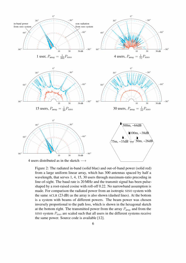
3 Line-of-Sight ChannelsFigure 2 illustrates how the in-band and OOB beampatterns from a large array differin line-of-sight. It also shows how they compare to an omnidirectional SISO system,whose transmit signal has the same ACLR as the transmit signals of the array, and whosetransmit power is chosen such that all users receive the same in-band power. We see thatthere are bad directions, in which the OOB radiation is stronger, and that there can begood directions, in which there is very little OOB radiation.
Note that the radiation pattern in a multi-user case can be similar to the single-usercase with only one visible beam. This happens when users experience very different
4
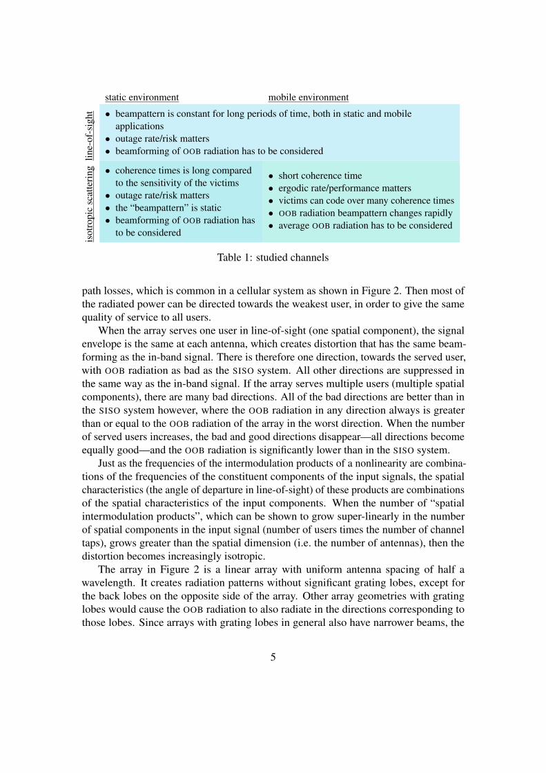
static environment mobile environmentlin
e-of
-sig
ht • beampattern is constant for long periods of time, both in static and mobileapplications
• outage rate/risk matters• beamforming of OOB radiation has to be considered
isot
ropi
csc
atte
ring • coherence times is long compared
to the sensitivity of the victims• outage rate/risk matters• the “beampattern” is static• beamforming of OOB radiation has
to be considered
• short coherence time• ergodic rate/performance matters• victims can code over many coherence times• OOB radiation beampattern changes rapidly• average OOB radiation has to be considered
Table 1: studied channels
path losses, which is common in a cellular system as shown in Figure 2. Then most ofthe radiated power can be directed towards the weakest user, in order to give the samequality of service to all users.
When the array serves one user in line-of-sight (one spatial component), the signalenvelope is the same at each antenna, which creates distortion that has the same beam-forming as the in-band signal. There is therefore one direction, towards the served user,with OOB radiation as bad as the SISO system. All other directions are suppressed inthe same way as the in-band signal. If the array serves multiple users (multiple spatialcomponents), there are many bad directions. All of the bad directions are better than inthe SISO system however, where the OOB radiation in any direction always is greaterthan or equal to the OOB radiation of the array in the worst direction. When the numberof served users increases, the bad and good directions disappear—all directions becomeequally good—and the OOB radiation is significantly lower than in the SISO system.
Just as the frequencies of the intermodulation products of a nonlinearity are combina-tions of the frequencies of the constituent components of the input signals, the spatialcharacteristics (the angle of departure in line-of-sight) of these products are combinationsof the spatial characteristics of the input components. When the number of “spatialintermodulation products”, which can be shown to grow super-linearly in the numberof spatial components in the input signal (number of users times the number of channeltaps), grows greater than the spatial dimension (i.e. the number of antennas), then thedistortion becomes increasingly isotropic.
The array in Figure 2 is a linear array with uniform antenna spacing of half awavelength. It creates radiation patterns without significant grating lobes, except forthe back lobes on the opposite side of the array. Other array geometries with gratinglobes would cause the OOB radiation to also radiate in the directions corresponding tothose lobes. Since arrays with grating lobes in general also have narrower beams, the
5
−90◦
−60◦
−30◦0◦
30◦
60◦
90◦10 30 50 dB
oob radiationfrom siso system
in-band powerfrom siso system
1 user, Parray =1
300PSISO
−90◦
−60◦
−30◦0◦
30◦
60◦
90◦10 30 50 dB
4 users, Parray =175PSISO
−90◦
−60◦
−30◦0◦
30◦
60◦
90◦10 30 50 dB
15 users, Parray =120PSISO
−90◦
−60◦
−30◦0◦
30◦
60◦
90◦10 30 50 dB
30 users, Parray =110PSISO
−90◦
−60◦
−30◦0◦
30◦
60◦
90◦10 30 50 dB
4 users distributed as in the sketch −→
500m, −64dB
100m, −38dB
50m, −26dB75m, −33dB
Figure 2: The radiated in-band (solid blue) and out-of-band power (solid red)from a large uniform linear array, which has 300 antennas spaced by half awavelength, that serves 1, 4, 15, 30 users through maximum-ratio precoding inline-of-sight. The baud rate is 20 MHz and the transmit signal has been pulse-shaped by a root-raised cosine with roll-off 0.22. No narrowband assumption ismade. For comparison the radiated power from an isotropic SISO system withthe same ACLR (23 dB) as the array is also shown (dashed lines). At the bottomis a system with beams of different powers. The beam power was choseninversely proportional to the path loss, which is shown in the hexagonal sketchat the bottom right. The transmitted power from the array Parray and from theSISO system PSISO are scaled such that all users in the different systems receivethe same power. Source code is available [12].
6
probability that a victim ends up in a beam of OOB radiation is not significantly changedby different array geometries. Furthermore, the OOB radiation in the directions of thegrating lobes is still smaller than in the SISO system. The radiation patterns studied inFigure 2 have the same basic appearance for any array type.
It is important to note that the array has no directions with worse OOB radiation thanthe SISO system. Since the in-band signal is beamformed to maximize its array gain, theOOB radiation can at most obtain the same array gain as the in-band signal, and thereforethe OOB radiation is never stronger than in a SISO system with the same ACLR.
There is a small risk that a victim stands in a bad direction, especially if few users areserved. The worst case is when a system serves one user and a victim stands in the samedirection as that user. In this case, the victim receives as much OOB radiation as fromthe SISO system. The probability that an unfortunate victim stands in a bad directionbecomes smaller as the number of antennas grows large, and the main lobe becomesincreasingly narrow.
Based on this discussion, we make the following observations:
(i) Keeping the same ACLR requirements as in legacy systems would guarantee thatno victim, not even the most unfortunate one, receives more OOB power than froma legacy system. The ACLR requirement does not have to be more stringent.
(ii) If multiple users are served, the OOB radiation can be treated as isotropic and thelegacy ACLR requirement can be relaxed.
(iii) If a single user is served, the OOB radiation is highly directive and the legacy ACLR
requirement can be relaxed if a certain probability is allowed that an unfortunatevictim ends up in an OOB lobe. This probability is increasingly small when thearray is large.
4 Static Channels with Isotropic FadingThe received OOB radiation varies with the channels to the victim and the served users.If the channel changes slowly or if the victim systems is sensitive to outage, e.g. whenthere are high reliability or latency requirements, the OOB radiation has to be constrainedduring every channel realization. Much of what was said in Section 3 about staticline-of-sight channels carries over to slowly changing frequency-selective channels withisotropic fading. One difference, however, comes from the larger number of propagationpaths.
A consequence of the multipath propagation of wideband signals is frequency-selective fading. The multiple taps of the channel make the OOB radiation less directivein much the same way as serving more users. Therefore, also when a single user is served
7
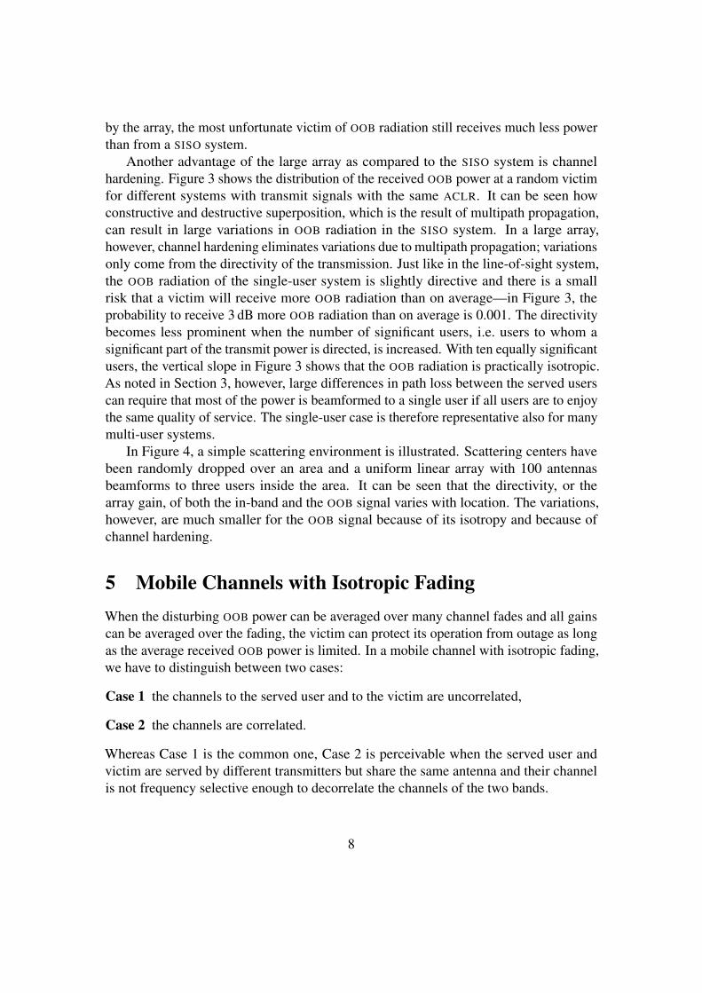
by the array, the most unfortunate victim of OOB radiation still receives much less powerthan from a SISO system.
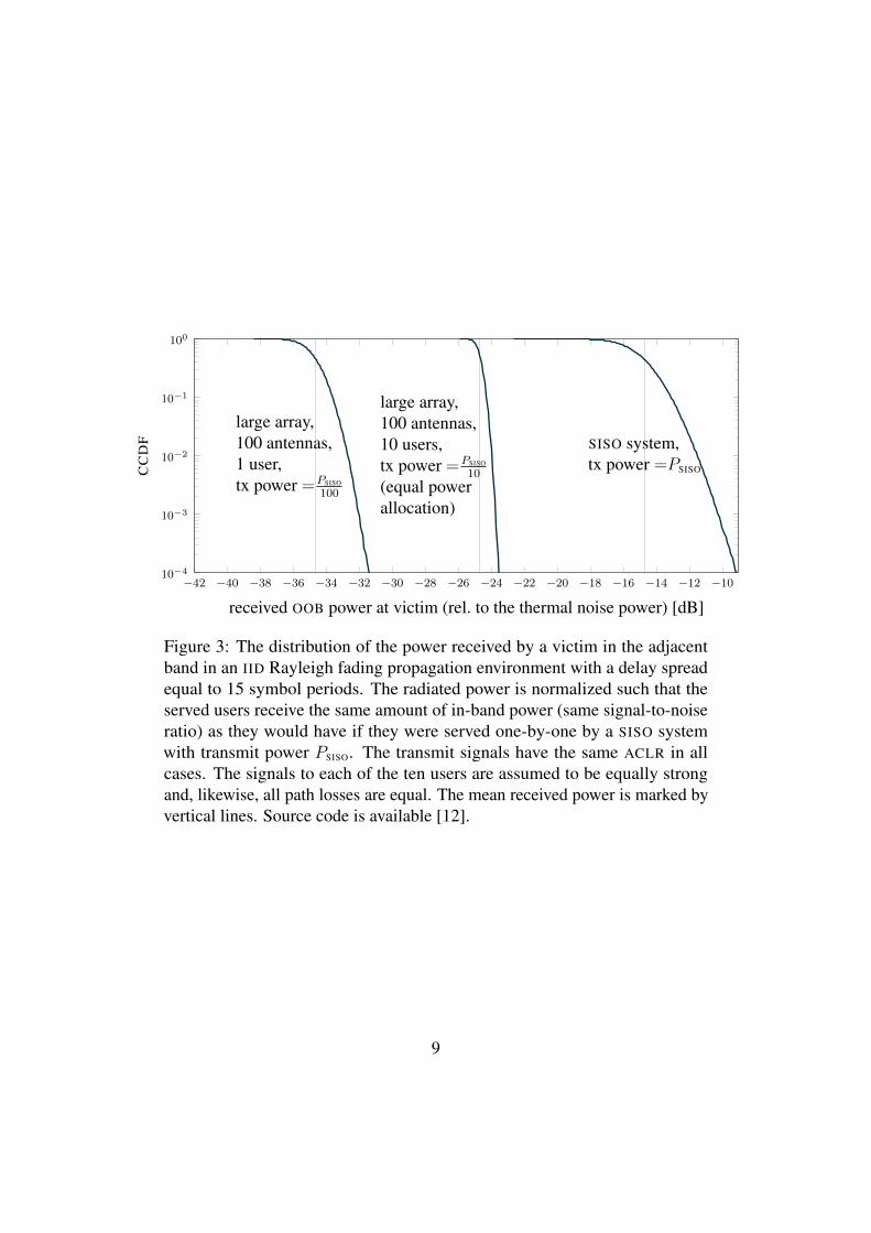
Another advantage of the large array as compared to the SISO system is channelhardening. Figure 3 shows the distribution of the received OOB power at a random victimfor different systems with transmit signals with the same ACLR. It can be seen howconstructive and destructive superposition, which is the result of multipath propagation,can result in large variations in OOB radiation in the SISO system. In a large array,however, channel hardening eliminates variations due to multipath propagation; variationsonly come from the directivity of the transmission. Just like in the line-of-sight system,the OOB radiation of the single-user system is slightly directive and there is a smallrisk that a victim will receive more OOB radiation than on average—in Figure 3, theprobability to receive 3 dB more OOB radiation than on average is 0.001. The directivitybecomes less prominent when the number of significant users, i.e. users to whom asignificant part of the transmit power is directed, is increased. With ten equally significantusers, the vertical slope in Figure 3 shows that the OOB radiation is practically isotropic.As noted in Section 3, however, large differences in path loss between the served userscan require that most of the power is beamformed to a single user if all users are to enjoythe same quality of service. The single-user case is therefore representative also for manymulti-user systems.
In Figure 4, a simple scattering environment is illustrated. Scattering centers havebeen randomly dropped over an area and a uniform linear array with 100 antennasbeamforms to three users inside the area. It can be seen that the directivity, or thearray gain, of both the in-band and the OOB signal varies with location. The variations,however, are much smaller for the OOB signal because of its isotropy and because ofchannel hardening.
5 Mobile Channels with Isotropic FadingWhen the disturbing OOB power can be averaged over many channel fades and all gainscan be averaged over the fading, the victim can protect its operation from outage as longas the average received OOB power is limited. In a mobile channel with isotropic fading,we have to distinguish between two cases:
Case 1 the channels to the served user and to the victim are uncorrelated,
Case 2 the channels are correlated.
Whereas Case 1 is the common one, Case 2 is perceivable when the served user andvictim are served by different transmitters but share the same antenna and their channelis not frequency selective enough to decorrelate the channels of the two bands.
8
−42 −40 −38 −36 −34 −32 −30 −28 −26 −24 −22 −20 −18 −16 −14 −12 −1010−4
10−3
10−2
10−1
100
SISO system,tx power =PSISO
large array,100 antennas,1 user,tx power =PSISO
100
large array,100 antennas,10 users,tx power =PSISO
10
(equal powerallocation)
received OOB power at victim (rel. to the thermal noise power) [dB]
CC
DF
Figure 3: The distribution of the power received by a victim in the adjacentband in an IID Rayleigh fading propagation environment with a delay spreadequal to 15 symbol periods. The radiated power is normalized such that theserved users receive the same amount of in-band power (same signal-to-noiseratio) as they would have if they were served one-by-one by a SISO systemwith transmit power PSISO. The transmit signals have the same ACLR in allcases. The signals to each of the ten users are assumed to be equally strongand, likewise, all path losses are equal. The mean received power is marked byvertical lines. Source code is available [12].
9

map
0 50 100 150 200 250 300
−100
−50
0
50
100
← base station
east–west position [m]
north
–sou
thpo
sitio
n[m
]
base station antennaserved userscatterer
in-band power
−52 −50 −48 −46 −44 −4210−3
10−2
10−1
in-band power [dB]
distr
ibut
ion
OOB power
−77 −75 −73 −71 −69 −6710−3
10−2
10−1
oob power [dB]
distr
ibut
ion
Figure 4: Heat map of in-band and OOB signal power intensity over the areamarked � in the uppermost figure, where the geometry of the setup can be seen.A linear uniform array with 100 antennas, half a wavelength apart, is locatedat the origin and 20 scatterers and three users are randomly placed in a 100 mlarge quadratic area 250 m east of the array. The empirical distribution of thereceived power over the shown area is given to the left of the figures. Sourcecode is available [12].
10
In Case 1, the average OOB power that the victim receives, normalized by the pathloss, is determined by the total radiated OOB power at the transmitter, both for legacysystems and for large arrays. Given a transmit power, an ACLR constraint thus limitshow much OOB power that a victim receives on average, which is enough to protect theoperation of the victim. When the correlation is high, the OOB radiation of Case 2 has tobe analyzed as in the static case, since the OOB radiation to the victim then experiencesan array gain also when averaged over many fades.
Since less radiated power is required from a large array than from a legacy system fora given received in-band power, the average received OOB power is also correspondinglylower when the transmit signals of two systems have the same ACLR, which was seenin Figure 3. The ACLR requirement should therefore be relaxed for the large array ascompared to the legacy system by the same amount, by which the total radiated power isreduced. Since the in-band array gain grows with the number of antennas of the array,the ACLR requirement can be relaxed more, the more antennas the array has. However,the radiated power also increases with the number of served users and varies slightlydepending on the employed beamforming technique. Therefore the ACLR requirementhas to be specified in terms of these system parameters or set according to the worstscenario, in which the most OOB power is radiated.
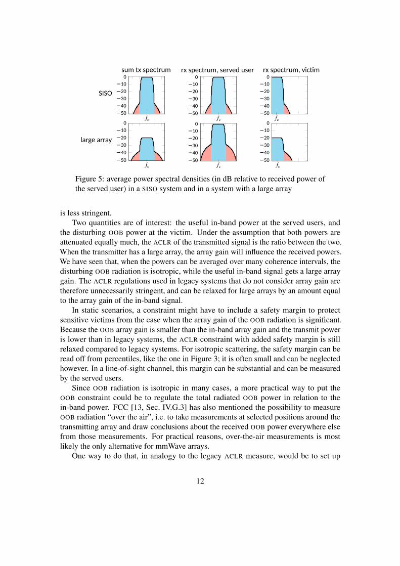
Figure 5 shows the average power spectral densities of two example scenarios; thepath loss has been normalized for simplicity. In the legacy SISO case, highly linearhardware gives the transmitted signal a good ACLR. Consequently, the served userreceives a sufficient amount of in-band power and, at the same time, the victim whooperates in the adjacent band receives little disturbing power. In the large array case, thetransmitted signal has an ACLR that is seemingly worse because less linear hardware isused; the transmitted power is also smaller. Because the signal is beamformed, however,the served user still receives a sufficient amount of in-band power. At the same time, thevictim receives little disturbing power on average. This example shows that the ACLR
constraint of SISO systems cannot directly be applied to arrays. The array gain of thein-band signal at the served users and the distribution of the OOB signal at the victim alsohave to be taken into account.
6 How to Measure OOB RadiationTo mitigate the disturbance of other systems, most communication standards, such asWCDMA, LTE, WiFi, and national regulatory bodies, such as FCC (the Federal Communi-cations Commission) in the United States, limit the amount of permitted OOB radiation.This is usually done by enforcing a constraint on the ACLR of the transmit signal and amaximum power level for the emitted OOB signal. For example, in LTE, the ACLR hasto be better than 45 dBc or the absolute power spectral density of the signal in a wideoutdoor area has to be lower than −13 dBm/MHz outside the allocated band, whichever
11
SISO
sum tx spectrum
−50
−40
−30
−20
−10
0
−50
−40
−30
−20
−10
0
rx spectrum, served user
−50
−40
−30
−20
−10
0
−50
−40
−30
−20
−10
0
rx spectrum, vic�m
−50
−40
−30
−20
−10
0
−50
−40
−30
−20
−10
0fc fc
fcfc
fc
fc
large array
Figure 5: average power spectral densities (in dB relative to received power ofthe served user) in a SISO system and in a system with a large array
is less stringent.Two quantities are of interest: the useful in-band power at the served users, and
the disturbing OOB power at the victim. Under the assumption that both powers areattenuated equally much, the ACLR of the transmitted signal is the ratio between the two.When the transmitter has a large array, the array gain will influence the received powers.We have seen that, when the powers can be averaged over many coherence intervals, thedisturbing OOB radiation is isotropic, while the useful in-band signal gets a large arraygain. The ACLR regulations used in legacy systems that do not consider array gain aretherefore unnecessarily stringent, and can be relaxed for large arrays by an amount equalto the array gain of the in-band signal.
In static scenarios, a constraint might have to include a safety margin to protectsensitive victims from the case when the array gain of the OOB radiation is significant.Because the OOB array gain is smaller than the in-band array gain and the transmit poweris lower than in legacy systems, the ACLR constraint with added safety margin is stillrelaxed compared to legacy systems. For isotropic scattering, the safety margin can beread off from percentiles, like the one in Figure 3; it is often small and can be neglectedhowever. In a line-of-sight channel, this margin can be substantial and can be measuredby the served users.
Since OOB radiation is isotropic in many cases, a more practical way to put theOOB constraint could be to regulate the total radiated OOB power in relation to thein-band power. FCC [13, Sec. IV.G.3] has also mentioned the possibility to measureOOB radiation “over the air”, i.e. to take measurements at selected positions around thetransmitting array and draw conclusions about the received OOB power everywhere elsefrom those measurements. For practical reasons, over-the-air measurements is mostlikely the only alternative for mmWave arrays.
One way to do that, in analogy to the legacy ACLR measure, would be to set up
12
a controlled environment and let the array beamform a signal to a served user in itsnormal operational mode. Then measure the useful in-band power at the served user andthe disturbing OOB power at a reference victim. The ratio between the two—the arrayACLR—can then be constrained in the same way as in legacy systems. The reason foremploying such a strategy would be to avoid measuring directly on each of the individualtransmit signals in the array and to make the constraint independent of the number ofantennas and other system parameters.
If the same transmitted power is used as in legacy systems, the OOB constraintcannot necessarily be relaxed as compared to legacy systems. An stricter OOB constraint,however, is only necessary if there is a non-negligible risk that the array gain of thedisturbing OOB radiation at a victim is large. We have shown how this risk is increasinglysmall for large arrays. Furthermore, as discussed in Section 2, to use the same transmitpower as in a legacy system is seldom necessary.
7 ConclusionWe have shown how a victim, on average, receives less OOB radiation from base stationswith large arrays than from legacy systems with the same ACLR requirement for a givenreceived SNR requirement. In the worst case, the victim receives the same amount ofOOB radiation as from the legacy system. However, this worst case event occurs onlywhen most of the transmitted power is directed towards a single user whose channelimpulse response consists of taps that are all linearly dependent, and then only with asmall probability. Furthermore, the probability grows increasingly small as the numberof antennas grows large.
This conclusion relies on the assumption that the channel to the victim is uncorrelatedto the channel of the served users. If that is not true, for example if the victim shares itsantenna with one of the served users, the probability that the victim receives the sameamount of OOB radiation as from the legacy system can increase significantly. However,the OOB radiation is never greater than from the legacy system.
When the dimension of the space spanned by the channel vectors of the served usersis large, which happens with high probability when the product of the number of usersand number of channel taps is large, the OOB radiation becomes close to isotropic. Thismakes it redundant to measure the radiation pattern for each setup, which simplifies themeasurement of OOB radiation.
This suggests that relaxed ACLR and linearity constraints can be used for the hardwarein large arrays. To set appropriate linearity requirements on the hardware is important,because it will be decisive for how future radio equipment will be designed. Especiallysince it is desirable to build large arrays without high-end hardware or advanced com-pensation techniques, which become impediments as the number of radio chains grows[14, 15]. The linearity requirement will determine what amplifier architectures, digital-
13
to-analog converters etc. that have to be employed. It will also influence what signalprocessing is required, such as predistortion, PAR reduction and low-PAR precoding.Power efficiency, system complexity, cost and size of future communication systems willall be affected by the way OOB radiation from large arrays is regulated.
References[1] F. Boccardi, R. W. Heath, Jr., A. Lozano, T. L. Marzetta, and P. Popovski, “Five
disruptive technology directions for 5G,” IEEE Commun. Mag., vol. 52, no. 2, pp.74–80, Feb. 2014.
[2] T. L. Marzetta, E. G. Larsson, H. Yang, and H. Q. Ngo, Fundamentals of MassiveMIMO. Cambridge University Press, 2016.
[3] K. G. Gard, H. M. Gutierrez, and M. B. Steer, “Characterization of spectral regrowthin microwave amplifiers based on the nonlinear transformation of a complex Gaus-sian process,” IEEE Trans. Microw. Theory Tech., vol. 47, no. 7, pp. 1059–1069,Jul. 1999.
[4] M. H. Ng, S.-D. Lin, J. Li, and S. Tatesh, “Coexistence studies for 3GPP LTE withother mobile systems,” IEEE Commun. Mag., vol. 47, no. 4, pp. 60–65, Apr. 2009.
[5] W. Sandrin, “Spatial distribution of intermodulation products in active phased arrayantennas,” IEEE Trans. Antennas Propag., vol. 21, no. 6, pp. 864–868, Nov. 1973.
[6] C. Hemmi, “Pattern characteristics of harmonic and intermodulation products inbroadband active transmit arrays,” IEEE Trans. Antennas Propag., vol. 50, no. 6,pp. 858–865, Jun. 2002.
[7] Y. Zou, O. Raeesi, L. Antilla, A. Hakkarainen, J. Vieira, F. Tufvesson, Q. Cui,and M. Valkama, “Impact of power amplifier nonlinearities in multi-user massiveMIMO downlink,” in Proc. IEEE Globecom Workshops, Dec. 2015, pp. 1–7.
[8] C. Mollen, U. Gustavsson, T. Eriksson, and E. G. Larsson, “Out-of-band radiationmeasure for MIMO arrays with beamformed transmission,” in Proc. IEEE Int. Conf.Commun., May 2016, pp. 1–6.
[9] S. Mohammed and E. G. Larsson, “Constant-envelope multi-user precoding forfrequency-selective massive MIMO systems,” IEEE Wireless Commun. Lett., vol. 2,no. 5, pp. 547–550, Oct. 2013.
[10] O. Edfors and F. Tufvesson, “MaMi channel characteristics: Measurement results,”https://mammoet-project.eu/publications-deliverables, Massive MIMO for Efficient
14
Transmission (MAMMOET), Project Deliverable D1.2, Jun. 2015, online: accessed2016-10-26.
[11] M. Peter, K. Sakaguchi, S. Jaeckel, S. Wu, M. Nekovee, J. Medbo, K. Haneda,S. L. H. Nguyen, R. Naderpour, J. Vehmas, F. Mani, A. Bamba, R. D’Errico,M. Rybakowski, J.-M. Conrat, A. Goulianos, P. Cain, M. Rumney, M. Dieudonne,H. Wang, and M. Kottkamp, “Measurement campaigns and initial channel mod-els for preferred suitable frequency ranges,” https://bscw.5g-mmmagic.eu/pub/bscw.cgi/93650, Millimetre-Wave Based Mobile Radio Access Network for FifthGeneration Integrated Communications (mmMagic), Project Deliverable H2020-ICT-671650-mmMAGIC/D2.1, Mar. 2016, online: accesed 2016-10-26.
[12] C. Mollen. (2016, Nov.) Source code for the analysis of out-of-band radiationfrom large arrays. [Online]. Available: https://github.com/OOBRadMIMO/NumericalResults
[13] “FCC 16-89 report and order and further notice of proposed rulemaking,” https://www.fcc.gov/document/spectrum-frontiers-ro-and-fnprm, Federal Communica-tions Commission, Tech. Rep., Jul. 2016, online: accessed 2016-10-26.
[14] U. Gustavsson, C. Sanchez Perez, T. Eriksson, F. Athley, G. Durisi, P. N. Landin,K. Hausmair, C. Fager, and L. Svensson, “On the impact of hardware impairmentson massive MIMO,” in Proc. IEEE Global Commun. Conf., Dec. 2014.
[15] E. Bjornson, M. Matthaiou, and M. Debbah, “Massive MIMO with non-idealarbitrary arrays: Hardware scaling laws and circuit-aware design,” IEEE Trans.Wireless Commun., vol. 14, no. 8, pp. 4353–4368, Aug. 2015.
15