Embed Size (px)
Citation preview

Outage and Rate Evaluation of Drone based Decodeand Forward Cooperation for Hybrid Fading
ChannelsNikita Goel and Vrinda Gupta, Member, IEEE
Abstract—In this paper, we consider a drone as a relay in Co-operative Communication (CC) to improve the network perfor-mance in an upcoming wireless network. Drone Assisted CC (DA-CC) is more useful when the central coordinator (base station)gets disrupted. In such a scenario, the drone works as an aerialrelay and provides CC diversity to the end-users. In this article, aDecode-and-Forward (DF) protocol is used as a relaying schemeat the drone, and the Maximal Ratio Combining (MRC) schemeis used at the end-users for combining the direct and relayedsignal. Here, we assume Nakagami faded channel among Air-to-Ground (A2G) links and Rayleigh faded distribution betweenGround-to-Ground (G2G) links. The performance of DA-CC isevaluated in a hybrid channel environment and compared basedon drone height, rate, horizontal distance, and transmitted powerwith the existing Rayleigh and Nakagami faded distributions.The analytical expression of outage probability and the rate havebeen derived for analysis purposes, and Monte-Carlo simulationsare used to verify the analytical results. This work can havesecurity and surveillance applications to improve the networkperformance in the absence of a central base station.
I. INTRODUCTION
Cooperative Communications (CC) meets the high datarate requirements of 5G wireless communications withoutincreasing bandwidth or power by enhancing system capacityand coverage [1]. Through developing virtual multiple antennaconnectivity environments, CC solves the effect of multipathfading by enabling cooperative diversity [1], [2]. The incor-poration of a CC relay channel provides separate pathwaysbetween the source and the end-users, and it is believed thateach wireless user (source) transmits data and supports anotherby using a cooperation strategy.
Different relaying schemes are used in CC for forwardingthe messages named as Amplify-and-Forward (AF), Decode-and-Forward (DF), etc. as explained by [2], [3]. Here we areusing DF as a relaying scheme for analysis purposes.
Manuscript received December 4, 2020; revised May 11, 2021. Date ofpublication June 16, 2021. Date of current version June 16, 2021. Theassociate editor prof. Francesca Vatta has been coordinating the review ofthis manuscript and approved it for publication.
N. Goel is pursuing PhD with the Department of Electronics and Commu-nication Engineering, National Institute of Technology Kurukshetra, India.Currently she is working as an Assistant Professor in the Department ofElectronics and Communication Engineering, K.I.E.T Group of InstitutionsDelhi NCR Ghaziabad, India (e-mail: [email protected]).
V. Gupta is with the Department of Electronics and CommunicationEngineering, National Institute of Technology Kurukshetra, India (e-mail:[email protected]).
Digital Object Identifier (DOI): 10.24138/jcomss-2020-0013
There are several sites, for example, unintended naturaldisaster zones, congested areas, mountain areas, or homes,where conventional cooperative networks are unable to provideQuality of Service (QoS) due to transmitter-receiver blockageor even a total lack of communication may occur [4]. Analternative link through relay networks consisting of dronesthat act as message forwarding nodes supporting transmitter-receiver communication is considered a possible solution tothis problem [5], [6].
Many researchers have studied CC using Unmanned AerialVehicle (UAV)/drone as a relay. In [7], a dual-hop CooperativeRelaying Strategy (CRS) for Non-orthogonal Multiple Access(NOMA) under Rayleigh fading has been proposed, and resultsare compared with the conventional scheme. The researchershave proposed a new opportunistic two-way relaying methodwhere sources are allowed to transmit without using distributedspace-time coding [8]. Performance analysis of the hybridrelaying scheme is investigated in [9] and compared with theexisting adaptive relaying scheme. In a similar way, authorsin [10] have derived Symbol Error Probability (SEP) by con-sidering hybrid decode amplify and forward relaying scheme.Ghofrani-Jahromi et al. [11] have derived outage probability,diversity order, and gain of the system in Nakagami fadedenvironment.
The Symbol Error Rate (SER) is calculated in Nakagamifaded environment using DF relaying scheme in [12]. Consid-ering the Nakagami fading environment, performance analysisof multiple dual-hop DF relay networks appears as mentionedin [13]. The analysis of the outage probability of dual-hopthreshold DF-based cooperative system for different relayselection schemes is presented in [14]. A hybrid techniqueis described in [15], to reduce the effects of Relay Node(RN) induced error propagation, considering both RN locationand RN-Bit Error Ratio (BER). In [16], under the Multi-ple Input Single Output (MISO) scenario, One Way RelayChannel (OWRC) has been studied. Outage probability anderror rate are derived in [17] using AF relaying scheme inNakagami faded environment. A comprehensive survey ofall developments promoting smooth integration of UAVs intocellular networks has been presented in [18]. Also, it providesa detailed insight into the type of consumer UAVs, interferenceissues, their solutions, challenges, opportunities of UAV-basedrelay communication systems and physical security issues ofUAV-assisted systems.
JOURNAL OF COMMUNICATIONS SOFTWARE AND SYSTEMS, VOL. 17, NO. 2, JUNE 2021 169
1845-6421/06/2020-0013 © 2021 CCIS

Bin Li et al. [19] have provided a brief understanding of5G wireless networks’ UAV communications and launchedadvanced space-air-ground networks. Various challenges facedby the system have been discussed in this paper. The ex-pression of optimal drone height is evaluated in [20] withoutconsidering the G2G link into consideration. In [21], the DF-based CC scenario under different channel conditions havebeen analyzed. The authors proposed a power allocation algo-rithm when all nodes are on the same horizon plane. A studyof the best relay selection technique in various cooperativerelaying schemes has been given in [22]. It explores howCC overcomes the challenges faced in 5G communicationsby millimeter-wave. The authors in [23] evaluated systemperformance using AF as a relaying scheme and MRC. FurtherSelection Combining (SC) has been taken for combiningthe signals at the destination. Besides, the Weibull channelis chosen for the source to relay and the source to thedestination connection, and the Rician channel for relay tothe destination link. Drone-based network coded cooperativecommunication has been analyzed in [24]. In [25], researchershave proposed a novel drone assisted network coded cooper-ation and analysed network coded noise expression. MultipleInput Multiple Output (MIMO) drone based cooperative re-transmission has been discussed in [26]. The authors of [27]have implemented a multiple drone system that consists of aquadcopter and demonstrate it in rescue operations. In [28],DA-CC performance assuming AF as relaying protocol hasbeen evaluated. Furthermore, in this work, the performancein the hybrid channel environment has been analyzed, andrate equations for different channel environments have beenderived. However, mathematical modeling for the same hasnot been provided.
This research paper provides a context for evaluating theperformance of DA-CC systems for DF relaying protocol overhybrid fading networks, unlike previous study from [28]. Ahybrid channel is considered a more practical scenario. There-fore this research work addresses the system performance inthis environment. Considering Nakagami and Rayleigh fading,this study extracts the closed-form approximate expressionof the outage over hybrid fading channels for analysis. Therate equation for DA-CC in different channel environments isalso given. With simulation outcomes, all analytical derivedexpressions are confirmed successfully.Our paper’s main contributions are summarized as follows:
• Unlike previously published work [28], we have analyzedthe performance of the CC system considering DF as arelaying scheme and using a drone as a relay which hap-pens to be more realistic hybrid fading climate. We haveconsidered three separate cases for analysis purposes.(i) All the links are faded from Rayleigh fading.(ii) S-R and R-D links are Nakagami faded, whileS-D link is Rayleigh faded (proposed hybrid channelenvironment).(iii) All the links have been faded from Nakagami fading.
• We have derived and provided mathematical modeling ofthe system’s rate equation for all the above-defined casesand verified the same with simulation results.
• Also, we have obtained the expression of the system out-age probability for various fading conditions and verifiedmathematical findings with simulation results.
The paper’s remainder is listed as follows. Section 2 introducesthe DA-CC system model, where the drone acts as a relaynode, and the DF is used as a relaying scheme. In section3, outage probability and rate equations for hybrid channelconditions are derived. In section 4, theoretical and simulatedobservations are drawn and analyzed. Section 5 concludes thefindings of this study.
SRh RDh
SDh
S D
R
O
dSR dRDDh
dSD
Fig. 1. System model for drone assisted cooperative communication.
II. SYSTEM MODEL
Fig.1 illustrates the proposed DA-CC network’s systemmodel, which includes a source, destination, and relay noderepresented as S, D, and R nodes, respectively. The drone(R) is deployed as a relay node to facilitate diversity betweenthe S and D nodes. Fig.1 indicates that in the first time slot,S transmits the data to R and D nodes. In the second timeslot, the relay fully decodes the received data from S andsends them to node D. We assume each node is equipped withone antenna and it transmits the signal in half-duplex mode.According to the coordinate system, the location of the S andD can be denoted by [xs ys 0] and [xd yd 0], respectively.The drone is assumed at fixed height hD, the location ofwhich is denoted by [xr yr hD]. Channel State Information(CSI) is known by a receiver node (R, D) only. However, theenergy-related problems of UAVs are not considered here. Thesymbols used in this paper are summarised in Table I.The transmission and reception scheme for DA-CC takes twotime slots. In the first time slot, S transmits the signal to D,which is overheard by the R node. The signal received at Dand R nodes in the first time slot is given as [6]:
Y ξ1SD =
√Psd
−αSD hξ1
SDx + nD , (1)
Y ξ2SR =
√Psd
−αSR hξ2
SRx + nR, (2)
170 JOURNAL OF COMMUNICATIONS SOFTWARE AND SYSTEMS, VOL. 17, NO. 2, JUNE 2021

TABLE ILIST OF NOTATIONS
Symbol DescriptionhD Height of the Drone from the ground levelYab Signal obtained by node bth from node ath
α Path loss exponentdij Distance between ith and jth nodehSR Channel coefficient between source-relay linkhRD Channel coefficient between relay-destination linkx Symbol transmitted from the sourcenR Relay node noisenD Destination node noiseB Bandwidthσ2 Variance of noiseCDA−CC Rate at destinationPS Power transmitted by source nodePR Power transmitted by relay nodeIDA−CC Mutual information between direct and relayed pathβ Power allocation factorPout Outage probabilityR Spectral Efficiencyχ Power Allocation Factor
where ξ1, ξ2 ∈ {Rayleigh(Ray), Nakagami(Nak)}, α denotesthe path loss exponent, Y ξ1
SD, Y ξ2SR denotes the signal received
at D and R node while the signal is transmitted by S node.PS represents the power transmitted by the S node, x denotesthe message signal transmitted by node S, and hξ1
SD, hξ2SR
represents the channel coefficient between S-D and S-R links,respectively. Additive White Gaussian Noise (AWGN) noiseat node R and D are represented by nR and nD with zeromean and variance σ2
R and σ2D. The distance between S-R,
S-D, and R-D nodes is denoted by dSR, dSD and dRD,respectively. In this work, we assume R is moving verticallyeither upward or downward for a fixed position of S and Dnodes or moving horizontally between S and D nodes forgiven hD. For simplicity, the distance between S-R link andS-D link is assumed to be equal and is given as:
dRD = dSR =
√h2D +
(dSD
2
)2
. (3)
Here, R fully decodes the signal received from S in the firsttime slot using DF as relaying scheme and sends the decodedsignal towards the D node in the second time slot. The signalreceived at D in the second time slot is given as:
Y ξ2RD =
√PRd
−αRDhξ2
RDx+ nD, (4)
where PR represents the relay transmitted power. This paperhas considered DA-CC under different channel environmentssuch as Rayleigh and Nakagami fading environments. For eval-uating the system performance, three different cases of channelenvironment have been considered, which are described asfollows:Case 1: In the first case, all the links are Rayleigh distributed.Case 2: In the second case, a hybrid channel environmentis considered, as shown in Fig.2. In this case, the S-D linkis Rayleigh distributed because of assuming only the Non-Line of Sight (NLoS) component is received at node D.We also assume A2G links (S-R and R-D links) to beNakagami distributed because of the Line of Sight (LoS)
component being received at receiving node (R and D) dueto vertical movement of the drone. For simplicity, we haveconsidered Nakagami fading with shaping parameter (m=2)for developing the analytical framework. In the future, it canbe generalized for other values of m.
st1
nd2 Time slot
S D
NLoS component
R
Time slot
Fig. 2. Illustration of DA-CC scenario where dissimilar obstacles in S andD channels lead to Rayleigh fading. In particular, S-R and R-D links aredominated by LoS components (modelled by Nakagami distribution).
Case 3: In the third case, all the links are Nakagami dis-tributed.The generalized power allocation scheme used in our systemmodel is given as:
PS = χPT
PR = (1− χ)PT ,(5)
where χ denotes the power allocation factor and PT representsthe power constraint which can be given as PS + PR = PT .
III. OUTAGE AND RATE EVALUATION OF DA-CC
In this section, the analytical expressions for rate and outageprobability are derived for evaluating the system performanceunder the different channel conditions.
A. Rate Analysis
Let t seconds be the time needed to complete the entireprocess of communication in this setup, and let t
2 secondsbe the time allotted to each phase. Likewise, let bandwidthavailable in the network be denoted by B and bandwidthassigned to each time slot be B
2 . Using MRC at node D forcombining the direct component (S-D) and relayed component(S-R-D) of signals under consideration, and the rate equationcan be written as:
Cξ1,ξ2DA-CC =
(B
2
)Iξ1,ξ2DA-CC, (6)
where Iξ1,ξ2DA-CC denotes the mutual information between S-Dand S-R-D path in consideration, further it can be defined as:
Iξ1,ξ2DA-CC = min{log2(1+SNRξ2SR), log2(1+SNRξ1
SD+SNRξ2RD)},
(7)
N. GOEL et al.: OUTAGE AND RATE EVALUATION OF DRONE BASED DECODE AND FORWARD COOPERATION 171
where SNRξ1SD denotes Signal to Noise Ratio (SNR) at node
D when taking S-D link in consideration. It is defined as:
SNRξ1SD =
Psd−αSD|hξ1
SD|2
σ2D
, (8)
where SNR at node R and D is denoted by SNRξ2SR and
SNRξ2RD and defined as:
SNRξ2SR =
(PRd−αSR|h
ξ2SR|2)
σ2R
,
SNRξ2RD =
(PRd−αRD|hξ2
RD|2)σ2D
.
(9)
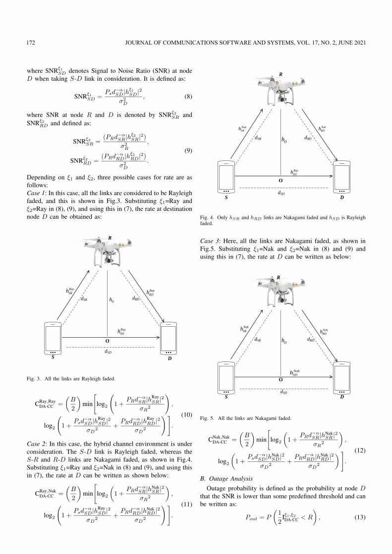
Depending on ξ1 and ξ2, three possible cases for rate are asfollows:Case 1: In this case, all the links are considered to be Rayleighfaded, and this is shown in Fig.3. Substituting ξ1=Ray andξ2=Ray in (8), (9), and using this in (7), the rate at destinationnode D can be obtained as:
S D
R
dSD
dRDdSRDh
O
Ray
SDh
Ray
RDhRay
SRh
Fig. 3. All the links are Rayleigh faded.
CRay,RayDA-CC =
(B
2
)min
[log2
(1 +
PRd−αSR|h
RaySR|2
σR2
),
log2
(1 +
Psd−αSD|hRay
SD|2
σD2
+PRd
−αRD|hRay
RD|2
σD2
)].
(10)
Case 2: In this case, the hybrid channel environment is underconsideration. The S-D link is Rayleigh faded, whereas theS-R and R-D links are Nakagami faded, as shown in Fig.4.Substituting ξ1=Ray and ξ2=Nak in (8) and (9), and using thisin (7), the rate at D can be written as shown below:
CRay,NakDA-CC =
(B
2
)min
[log2
(1 +
PRd−αSR|hNak
SR |2
σR2
),
log2
(1 +
Psd−αSD|hRay
SD|2
σD2
+PRd
−αRD|hNak
RD|2
σD2
)].
(11)
S D
R
dSD
dSR dRDDh
O
Nak
SRh Nak
RDh
Ray
SDh
Fig. 4. Only hSR and hRD links are Nakagami faded and hSD is Rayleighfaded.
Case 3: Here, all the links are Nakagami faded, as shown inFig.5. Substituting ξ1=Nak and ξ2=Nak in (8) and (9) andusing this in (7), the rate at D can be written as below:
S D
R
dSD
O
DhdSR dRD
Nak
SRh Nak
RDh
Nak
SDh
Fig. 5. All the links are Nakagami faded.
CNak,NakDA-CC =
(B
2
)min
[log2
(1 +
PRd−αSR|hNak
SR |2
σR2
),
log2
(1 +
Psd−αSD|hNak
SD|2
σD2
+PRd
−αRD|hNak
RD|2
σD2
)].
(12)
B. Outage AnalysisOutage probability is defined as the probability at node D
that the SNR is lower than some predefined threshold and canbe written as:
Pout = P
(1
2Iξ1,ξ2DA-CC < R
), (13)
172 JOURNAL OF COMMUNICATIONS SOFTWARE AND SYSTEMS, VOL. 17, NO. 2, JUNE 2021

where Pout denotes the outage probability at desired node.Putting (7) in (13), outage probability for DA-CC using DFas relaying scheme can be obtained as:
Pout = P (min{log2(1 + SNRξ2SR),
log2(1 + SNRξ1SD + SNRξ2
RD)} < T ),(14)
where T=22R − 1 and T is some dummy value dependingupon receiver sensitivity. Using probability theory, (14) canbe written as:
Pout = P [SNRξ2SR < T ]︸ ︷︷ ︸
1st term
+P [SNRξ2SR > T ]︸ ︷︷ ︸
2nd term
P [SNRξ1SD + SNRξ2
RD < T ]︸ ︷︷ ︸3rd term
.(15)
Depending upon ξ1 and ξ2, three cases for outage probabilityare possible, which are discussed as follows:Case 1: In this case, all the channels are considered Rayleighfaded. Putting ξ1=ξ2=Ray in (15), the solution of 1st term canbe obtained as:
P [SNRRaySR < T ] = 1− e−λSRT , (16)
where λSR= σ2R
PSd−αSR
. Solution of 2nd term can be obtained with
the help of (16). Before finding the 3rd term solution, we needthe Probability Density Function (PDF) of the 3rd term. Let3rd term be denoted by Z, and its PDF for λSD=λRD=λ (rateparameter) can be obtained as:
fZ(z) = λ2ze−(λ)z. (17)
Using (17) in 3rd term of (15), the solution of 3rd term canbe obtained as :
P [SNRRaySD + SNRRay
RD < T ] =
T∫0
fZ(z)dz. (18)
After integration, 3rd term is obtained as:
P [SNRRaySD + SNRRay
RD < T ] = 1− e−(λ)z(1 + λT ). (19)
Putting (16) and (19) in (15), the outage probability for thiscase can be obtained as:
Pout = (1− e−(λ)z) + (e−(λ)z)(1− e−(λ)z(1 + λT )). (20)
Case 2: In this case, S-R and R-D channels are considered asNakagami faded, and channel S-D as Rayleigh faded. Puttingξ1=Ray and ξ2=Nak in (15), outage probability in a hybridchannel environment can be obtained as:
Pout = P [SNRNakSR < T ]︸ ︷︷ ︸
1st term
+P [SNRNakSR > T ]︸ ︷︷ ︸
2nd term
P [SNRRaySD + SNRNak
RD < T ]︸ ︷︷ ︸3rd term
.(21)
Considering shaping index profile, m of Nakagami fadedchannel as 2, the SNR equation between S-R link can beshown as:
SNRNakSR =
PSd−αSR|hSR1
|2
σ2R
+PSd
−αSR|hSR2
|2
σ2R
. (22)
Let SNRNakSR be denoted by X1, and by using transformation
in (22), PDF of X1 can be obtained as:
fX1(x1) = λ2
SRx1e−λSRx1 , (23)
where λSR= σ2R
PSd−αSR
. For the same value of m, SNR equationbetween R-D link can be written as:
SNRNakRD =
PRd−αRD|hRD1 |2
σ2D
+PRd
−αRD|hRD2 |2
σ2D
. (24)
Let SNRNakRD be denoted by X2. By using transformation in
(22), PDF of X2 can be obtained as:
fX2(x2) = λ2
RDx2e−λRDx2 , (25)
where λRD= σ2D
PRd−αRD
. Solution of 1st and 2nd term can beobtained as:
P (SNRNakSR < T ) = 1− e−λT (1 + λT )
P (SNRNakSR > T ) = λ2Te−λT .
(26)
Before finding the solution of 3rd term, we need the PDFof 3rd term. Let 3rd term be denoted by Z, and its PDF forλSD=λRD=λ, can be obtained as:
fZ(z) =λ3z2e−λz
2. (27)
Using (27) in the 3rd term of (21), the solution of the 3rd
term can be shown as:
P [Z < T ] =
T∫0
fZ(z)dz. (28)
After integrating, 3rd term is obtained as:
P [Z < T ] = 0.5(−λTe−(λ)z(2 + T ) + 2(1− e−(λ)z)). (29)
Putting (26) and (29) in (21), outage probability for this casecan be obtained as:
Pout = [1− e−λT (1 + λT )] + [λ2Te−λT ][
0.5(−λTe−(λ)z(2 + T ) + 2(1− e−(λ)z))].(30)
Case 3: In this case, all the channels are assumed tobe Nakagami faded. Putting ξ1=ξ2=Nak in (15), it can berewritten as:
Pout = P [SNRNakSR < T ]︸ ︷︷ ︸
1st term
+P [SNRNakSR > T ]︸ ︷︷ ︸
2nd term
P [SNRNakSD + SNRNak
RD < T ]︸ ︷︷ ︸3rd term
.(31)
The solution of 1st and 2nd term is the same as obtained in(26). Before finding the solution of 3rd term, the PDF of 3rd
term is required to be obtained. Let 3rd term be denoted byZ, and its PDF for λSD=λRD=λ can be obtained as:
fZ(z) =λ4z3e−λz
3. (32)
Using (32) in the 3rd term of (21), the solution of the 3rd
term can be obtained as:
P [Z < T ] =
T∫0
fZ(z)dz. (33)
N. GOEL et al.: OUTAGE AND RATE EVALUATION OF DRONE BASED DECODE AND FORWARD COOPERATION 173

After integration, 3rd term can be obtained as:
P [Z < T ] =1
6(−λ3T 3e−(λ)z − 3λ2T 2e−(λ)z
−6λTe−(λ)z + 6(1− e−(λ)z)).(34)
Substituting (26) and (34) in (31), outage probability for thiscase can be given as:
Pout = [1− e−λT (1 + λT )] +1
6[λ2Te−λT ](−λ3T 3e−(λ)z−
3λ2T 2e−(λ)z − 6λTe−(λ)z + 6(1− e−(λ)z)).(35)
IV. RESULTS AND DISCUSSION
The analysis conducted in the previous section is validatedin this section. MATLAB R2013a® is used to perform simu-lation work. For the current analysis, simulation parametersused are summarized in Table II. The obtained results areevaluated and presented in Fig.6 to 12. Using DF as a relayingprotocol, with the help of outage probability and rate, DA-CCperformance has been evaluated.
TABLE IISIMULATION PARAMETERS
Simulation Parameters ValuesTransmitted Power (Pt) 10−3 wattNoise Power (σ2) 10−10 wattα 3hD 30 meterdSD 40 meterNumber of Iterations 105
Modulation Scheme BPSKShaping Parameter of Nakagami fading (m) 2
Fig. 6 shows the variation of outage probability with respectto drone height. From this result, it may be noted that outageprobability increases with drone height for all the three-channel models for a given source-destination node placement.It may also be noted here that the performance of the hybridchannel model is near to Nakagami faded (case 3). This is due
0 5 10 15 20 25 30
Drone height (meter)
10-5
10-4
10-3
10-2
10-1
Ou
tag
e p
rob
ab
ilit
y
Simulation
Analytical
Nakagami model
Hybrid modelRayleigh model
Fig. 6. Outage probability with respect to drone height.
to the fact that as the drone is placed at a greater height, theprobability of getting the LoS component increases. While the
performance of the Rayleigh faded model (case 1) is the worstamong all channel models.
Fig. 7 shows the variation of the outage probability with re-spect to the horizontal distance between the source-destinationpair of nodes under consideration of the different channelconditions. From this result, it is evident that as the horizontaldistance between nodes increases, performance goes downfor all the three cases. It is also noted here that Nakagamimodel (case 3) gives better performance in terms of outageprobability for a given horizontal distance between nodes andRayleigh model (case 1) give worse performance.
5 10 15 20 25 30 35 40
Horizontal distance between node (meter)
10-5
10-4
10-3
10-2
10-1
Ou
tag
e p
rob
ab
ilit
y
Simulation
Analytical
Nakagami model
Hybrid model
Rayleigh model
Fig. 7. Outage probability with respect to horizontal distance between S-Dpair of nodes.
Fig. 8 shows variation in the outage probability with respectto rate. It may be noted here, for different values of rate theoutcome corresponding to the proposed channel model (case2) lies nearer to the Nakagami faded channel model. Thismay happen because A2G characteristics of both the channelmodels are the same (case 2 and case 3). Decrements in the
0.5 1 1.5 2 2.5 3
Rate (bits/sec/Hz)
10-4
10-3
10-2
10-1
100
Ou
tag
e p
rob
ab
ilit
y
Simulation
Analytical
Hybrid model
Rayleigh model
Nakagami model
Fig. 8. Outage probability with respect to rate.
performance in terms of outage probability with increment inthe required rate for all the three-channel models is due to the
174 JOURNAL OF COMMUNICATIONS SOFTWARE AND SYSTEMS, VOL. 17, NO. 2, JUNE 2021

fact that channel gain continuously goes down for the largevalues of the required rate.
Variation in outage probability with respect to transmittedpower has been demonstrated in Fig.9. It is observed here thatthe probability of outage decreases as the transmitted powerincreases. It is also evident from this result that Nakagamimodel (case 3) provides better results, while Rayleigh model(case 1) provides worse performance in terms of outageprobability.
1 2 3 4 5 6 7 8 9
Transmitted power (watt) 10-3
10-7
10-6
10-5
10-4
10-3
10-2
10-1
Ou
tag
e p
rob
ab
ilit
y
Simulation
Analytical
Hybrid modelRayleigh model
Nakagami model
Fig. 9. Outage probability with respect to transmitted power in the presenceof different channel conditions.
The behavior of rate with respect to drone height has beendemonstrated in Fig. 10. It is noticed that for a given horizontaldistance, the rate decreases as drone height increases in allthree cases. For a given drone height, the performance of theNakagami model (case 3) is best, and Rayleigh model (case1) provides worse performance while the proposed hybridchannel model (case 2) performance lies very close to theNakagami one.
0 5 10 15 20 25 30
Drone height (meter)
3
3.2
3.4
3.6
3.8
4
4.2
4.4
4.6
Ra
te (
bit
s/s
ec
/Hz)
Simulation
Analytical
Nakagami model
Rayleigh model
Hybrid model
Fig. 10. Rate with respect to drone height.
The behavior of rate with respect to the horizontal distancebetween S-D pair of nodes is depicted in Fig.11 under
5 10 15 20 25 30 35 40
Horizontal distance between node (meter)
3.2
3.4
3.6
3.8
4
4.2
4.4
Ra
te (
bit
s/s
ec
/Hz)
Simulation
Analytical
Nakagami model
Hybrid model
Rayleigh model
Fig. 11. Rate with respect to the horizontal distance between S-D pair ofnodes.
different channel conditions. Here it can be observed thatas horizontal distance increases, the rate decreases. It is alsoevident from this result that Nakagami model (case 3) providesa better rate, while Rayleigh model (case 1) provides the worstrate for the given horizontal distance.
1 2 3 4 5 6 7 8 9
Transmitted power (watt) 10-3
3.2
3.4
3.6
3.8
4
4.2
4.4
4.6
4.8
5
5.2
Ra
te (
bit
s/s
ec
/Hz)
Simulation
Analytical
Rayleigh model
Nakagami model
Hybrid model
Fig. 12. Rate with respect to transmitted power.
Fig. 12 shows the variation in rate with respect to the trans-mitted power in the presence of different channel conditions.Here as transmitted power increases, it is observed that rateincreases. It is also evident from this result that Nakagamimodel (case 3) provides a better rate, while Rayleigh model(case 1) provides the worst rate for the given transmittedpower.
V. CONCLUSION
In this paper, performance analysis of drone-assisted coop-erative communication systems is carried out by using co-operation strategy over hybrid fading channels. The aboveperformance analysis is based on DF relaying protocol andMRC. The fact that in an urban area, where ground to ground
N. GOEL et al.: OUTAGE AND RATE EVALUATION OF DRONE BASED DECODE AND FORWARD COOPERATION 175

users cannot receive LOS component due to multiple obstacleshas been taken into account by considering Rayleigh fadingtherein. With the usage of the drone as a relay node, anadditional A2G path has been provided to ground users, whichprovides a better LOS component considered to be Nakagamifaded in the proposed system model. With this system model,outage probability and rate equations have been derived. Itis shown that the derived results agree with the simulationresults, which validates the theoretical analysis. Furthermore,it can be concluded that the performance of the system isgood over the hybrid fading channel, which appears to be veryclose to the system performance when all the channels areNakagami distributed. Whereas the performance is poor whenall the channels are Rayleigh distributed. In the future, we shallextend this work for a general value of shaping parameters(m) which depends on drone height and derive the analyticalexpression of outage and rate.
REFERENCES
[1] J. Laneman, D. Tse, and G. Wornell, “Cooperative diversity in wirelessnetworks: Efficient protocols and outage behavior,” IEEE Transactionson Information Theory, vol. 50, no. 12, pp. 3062–3080, 2004.
[2] T. Cover and A. Gamal, “Capacity theorems for the relay channel,” IEEETransactions on Information Theory, vol. 25, no. 5, pp. 572–584, 1979.
[3] S. Savazzi and U. Spagnolini, “Cooperative fading regions for decodeand forward relaying,” IEEE Transactions on Information Theory,vol. 54, no. 11, pp. 4908–4924, 2008.
[4] M. Mozaffari, W. Saad, M. Bennis, Y.-H. Nam, and M. Debbah, “Atutorial on uavs for wireless networks: Applications, challenges, andopen problems,” IEEE Communications Surveys Tutorials, vol. 21, no. 3,pp. 2334–2360, 2019.
[5] N. Zhao, W. Lu, M. Sheng, Y. Chen, J. Tang, F. R. Yu, and K.-K.Wong, “Uav-assisted emergency networks in disasters,” IEEE WirelessCommunications, vol. 26, no. 1, pp. 45–51, 2019.
[6] P. Kumar, S. Darshi, and S. Shailendra, “Drone assisted device to devicecooperative communication for critical environments,” IET Communica-tions, vol. 15, no. 7, pp. 957–972, 2021.
[7] M. F. Kader, M. B. Uddin, S. R. Islam, and S. Y. Shin, “Capacityand outage analysis of a dual-hop decode-and-forward relay-aided nomascheme,” Digital Signal Processing, vol. 88, pp. 138–148, 2019.
[8] Q. F. Zhou, Y. Li, F. C. M. Lau, and B. Vucetic, “Decode-and-forward two-way relaying with network coding and opportunistic relayselection,” IEEE Transactions on Communications, vol. 58, no. 11, pp.3070–3076, 2010.
[9] T. Q. Duong and H.-J. Zepernick, “Hybrid decode-amplify-forward co-operative communications with multiple relays,” in 2009 IEEE WirelessCommunications and Networking Conference, 2009, pp. 1–6.
[10] ——, “On the performance gain of hybrid decode-amplify-forwardcooperative communications,” EURASIP Journal on Wireless Commu-nications and Networking, vol. 2009, pp. 1–10, 2009.
[11] S. Ghofrani-Jahromi, A. Zolghadrasli, and M. Neinavaie, “Performanceanalysis of multihop decode-and-forward relay networks with diversityin nakagami fading channels,” AEU-International Journal of Electronicsand Communications, vol. 113, p. 152973, 2020.
[12] Y. Lee and M.-H. Tsai, “Performance of decode-and-forward cooperativecommunications over nakagami- m fading channels,” IEEE Transactionson Vehicular Technology, vol. 58, no. 3, pp. 1218–1228, 2009.
[13] Y. Lee, M.-h. Tsai, and S.-i. Sou, “Performance of decode-and-forward cooperative communications with multiple dual-hop relays overnakagami-m fading channels,” IEEE Transactions on Wireless Commu-nications, vol. 8, no. 6, pp. 2853–2859, 2009.
[14] J. Yao, J. Ye, G. Pan, Y. Xie, and Q. Feng, “Relay selection schemes inthreshold df cooperative systems with wireless power transfer,” Journalof the Franklin Institute, vol. 357, no. 8, pp. 5091–5109, 2020.
[15] D. Liang, S. X. Ng, and L. Hanzo, “Relay-induced error propagationreduction for decode-and-forward cooperative communications,” in 2010IEEE Global Telecommunications Conference GLOBECOM 2010, 2010,pp. 1–5.
[16] R. Mohseni and E. Daneshifar, “Robust cooperative beamforming formimo decode-and-forward one-way relay networks,” Physical Commu-nication, vol. 39, p. 100973, 2020.
[17] S. Ikki and M. H. Ahmed, “Performance analysis of cooperative diversitywireless networks over nakagami-m fading channel,” IEEE Communi-cations Letters, vol. 11, no. 4, pp. 334–336, 2007.
[18] A. Fotouhi, H. Qiang, M. Ding, M. Hassan, L. G. Giordano, A. Garcia-Rodriguez, and J. Yuan, “Survey on uav cellular communications:Practical aspects, standardization advancements, regulation, and securitychallenges,” IEEE Communications Surveys Tutorials, vol. 21, no. 4, pp.3417–3442, 2019.
[19] B. Li, Z. Fei, and Y. Zhang, “Uav communications for 5g and beyond:Recent advances and future trends,” IEEE Internet of Things Journal,vol. 6, no. 2, pp. 2241–2263, 2019.
[20] A. Al-Hourani, S. Kandeepan, and S. Lardner, “Optimal lap altitude formaximum coverage,” IEEE Wireless Communications Letters, vol. 3,no. 6, pp. 569–572, 2014.
[21] W. Wei, W. Zhang, and M. Yang, “Power allocation scheme for decode-and-forward cooperative communications in rician fading channels,” inInternational Conference on Wireless and Satellite Systems. Springer,2019, pp. 524–531.
[22] M. Asshad, S. A. Khan, A. Kavak, K. Kucuk, and D. L. Msongaleli,“Cooperative communications using relay nodes for next-generationwireless networks with optimal selection techniques: A review,” IEEETransactions on Electrical and Electronic Engineering, vol. 14, no. 5,pp. 658–669, 2019.
[23] J. Zakaria and M. F. M. Salleh, “Performance analysis of cooperativefixed-gain relaying system in severe fading channels,” IET Communica-tions, vol. 13, no. 14, pp. 2124–2131, 2019.
[24] P. Kumar, P. Singh, S. Darshi, and S. Shailendra, “Analysis of drone as-sisted network coded cooperation for next generation wireless network,”IEEE Transactions on Mobile Computing, vol. 20, no. 1, pp. 93–103,2021.
[25] ——, “Drone assisted network coded co-operation,” in TENCON 2019- 2019 IEEE Region 10 Conference (TENCON), 2019, pp. 1174–1179.
[26] T. Hiraguri, K. Nishimori, I. Shitara, T. Mitsui, T. Shindo, T. Kimura,T. Matsuda, and H. Yoshino, “A cooperative transmission scheme indrone-based networks,” IEEE Transactions on Vehicular Technology,vol. 69, no. 3, pp. 2905–2914, 2020.
[27] E. Yanmaz, S. Yahyanejad, B. Rinner, H. Hellwagner, and C. Bettstetter,“Drone networks: Communications, coordination, and sensing,” Ad HocNetworks, vol. 68, pp. 1–15, 2018.
[28] N. Goel and V. Gupta, “Performance analysis of drone assisted coop-erative communication in hybrid channel environment,” in 2019 IEEEInternational Conference on Advanced Networks and Telecommunica-tions Systems (ANTS), 2019, pp. 1–5.
Nikita Goel received her B.Tech degree in Electron-ics and Communication Engineering (First Divisionwith Honours) from Uttar Pradesh Technical Univer-sity, Lucknow and M.Tech degree with specializa-tion in Digital Communication (First Division withHonours) from Dr. A.P.J Abdul Kalam TechnicalUniversity, Lucknow, India. She has 8 years ofteaching experience. Currently she is working asAssistant Professor in KIET Group of Institutions,Delhi NCR, Ghaziabad, India, and also Part timeResearch Scholar in NIT Kurukshetra, Kurukshetra,
Haryana. Ms. Nikita Goel research and teaching interests are wireless com-munications, OFDM, cooperative communications and computer networks.
Vrinda Gupta is an Associate Professor in the De-partment of Electronics and Communication Engi-neering at NIT Kurukshetra. She is currently headingthe Department. She has worked as an EngineeringTeacher for more than 27 years. She received Ph.D.and M.Tech. degrees (Electronics and Communica-tion Engineering) from National Institute of Tech-nology Kurukshetra and B.E. degree in ElectronicsEngineering from Nagpur University. Dr. VrindaGupta’s research and teaching interests are in theareas of communication networks, and internet of
things. She is a member of professional societies, viz. IEEE, IETE, IAENG,and Fellow of IE (I).
176 JOURNAL OF COMMUNICATIONS SOFTWARE AND SYSTEMS, VOL. 17, NO. 2, JUNE 2021