Embed Size (px)
Citation preview
350 East Plumeria DriveSan Jose, CA 95134USA
October 2014202-11483-01
Outdoor High Power Wireless N Access PointModel WND930Reference Manual
2
Outdoor High Power Wireless N Access Point
SupportThank you for selecting NETGEAR products.
After installing your device, locate the serial number on the label of your product and use it to register your product at https://my.netgear.com. You must register your product before you can use NETGEAR telephone support. NETGEAR recommends registering your product through the NETGEAR website. For product updates and web support, visit http://support.netgear.com.
Phone (US & Canada only): 1-888-NETGEAR.
Phone (Other Countries): Check the list of phone numbers at http://support.netgear.com/general/contact/default.aspx.
ComplianceFor regulatory compliance information, visit http://www.netgear.com/about/regulatory.
See the regulatory compliance document before connecting the power supply.
TrademarksNETGEAR, the NETGEAR logo, and Connect with Innovation are trademarks and/or registered trademarks of NETGEAR, Inc. and/or its subsidiaries in the United States and/or other countries. Information is subject to change without notice.© NETGEAR, Inc. All rights reserved.
Contents
Chapter 1 Hardware Setup
System Requirements. . . . . . . . . . . . . . . . . . . . . . . . . . . . . . . . . . . . . . . . . . . . . . . . . .6Unpack Your Access Point . . . . . . . . . . . . . . . . . . . . . . . . . . . . . . . . . . . . . . . . . . . . . .6Front Panel . . . . . . . . . . . . . . . . . . . . . . . . . . . . . . . . . . . . . . . . . . . . . . . . . . . . . . . . . . .7
LEDs . . . . . . . . . . . . . . . . . . . . . . . . . . . . . . . . . . . . . . . . . . . . . . . . . . . . . . . . . . . . . .7Product Label . . . . . . . . . . . . . . . . . . . . . . . . . . . . . . . . . . . . . . . . . . . . . . . . . . . . . . . . .8Cable the Access Point for Initial Setup. . . . . . . . . . . . . . . . . . . . . . . . . . . . . . . . . . .8
Chapter 2 Initial Setup
Connect to the Access Point and Log In . . . . . . . . . . . . . . . . . . . . . . . . . . . . . . . . 11Specify the Access Point Name and Location . . . . . . . . . . . . . . . . . . . . . . . . . . . . 11Set the Time. . . . . . . . . . . . . . . . . . . . . . . . . . . . . . . . . . . . . . . . . . . . . . . . . . . . . . . . 12Configure the Basic IP Settings. . . . . . . . . . . . . . . . . . . . . . . . . . . . . . . . . . . . . . . . 13Configure the Access Point as a DHCP Server for Wireless Clients . . . . . . . . . 14Configure the Basic Wireless Settings . . . . . . . . . . . . . . . . . . . . . . . . . . . . . . . . . . 15Turn On the Wireless Signal and Test Connectivity . . . . . . . . . . . . . . . . . . . . . . . 18Plan Your Network Security . . . . . . . . . . . . . . . . . . . . . . . . . . . . . . . . . . . . . . . . . . 19Set Up Security Profiles . . . . . . . . . . . . . . . . . . . . . . . . . . . . . . . . . . . . . . . . . . . . . . 20Deploy the Access Point. . . . . . . . . . . . . . . . . . . . . . . . . . . . . . . . . . . . . . . . . . . . . . 22Connect Optional External Antennas . . . . . . . . . . . . . . . . . . . . . . . . . . . . . . . . . . . 24
Chapter 3 Network Settings
Spanning Tree Protocol . . . . . . . . . . . . . . . . . . . . . . . . . . . . . . . . . . . . . . . . . . . . . . 27Set Up a Schedule for the Wireless Radios . . . . . . . . . . . . . . . . . . . . . . . . . . . . . . 27Configure MAC Authentication. . . . . . . . . . . . . . . . . . . . . . . . . . . . . . . . . . . . . . . . 28Configure RADIUS Authentication . . . . . . . . . . . . . . . . . . . . . . . . . . . . . . . . . . . . . 29Configure Advanced Wireless Settings . . . . . . . . . . . . . . . . . . . . . . . . . . . . . . . . . 31Quality of Service Settings . . . . . . . . . . . . . . . . . . . . . . . . . . . . . . . . . . . . . . . . . . . 34Enable or Disable Wireless Multimedia QoS . . . . . . . . . . . . . . . . . . . . . . . . . . . . . 34
Configure Advanced QoS Settings. . . . . . . . . . . . . . . . . . . . . . . . . . . . . . . . . . . 35Wireless Bridging and Repeating. . . . . . . . . . . . . . . . . . . . . . . . . . . . . . . . . . . . . . . 37
Set Up a Wireless Point-to-Point Bridge . . . . . . . . . . . . . . . . . . . . . . . . . . . . . 37Set Up a Wireless Point-to-Multi-Point Bridge . . . . . . . . . . . . . . . . . . . . . . . . 39
Disable Ethernet LLDP . . . . . . . . . . . . . . . . . . . . . . . . . . . . . . . . . . . . . . . . . . . . . . . 42
Chapter 4 Manage the Access Point
Change the admin Password . . . . . . . . . . . . . . . . . . . . . . . . . . . . . . . . . . . . . . . . . . 44Reboot the Access Point . . . . . . . . . . . . . . . . . . . . . . . . . . . . . . . . . . . . . . . . . . . . . 44
3
Outdoor High Power Wireless N Access Point
Set Up a Remote Console. . . . . . . . . . . . . . . . . . . . . . . . . . . . . . . . . . . . . . . . . . . . . 45Set UP SNMP . . . . . . . . . . . . . . . . . . . . . . . . . . . . . . . . . . . . . . . . . . . . . . . . . . . . . . . 46Upgrade the Firmware . . . . . . . . . . . . . . . . . . . . . . . . . . . . . . . . . . . . . . . . . . . . . . . 47Manage the Configuration File . . . . . . . . . . . . . . . . . . . . . . . . . . . . . . . . . . . . . . . . 48
Back Up the Configuration File . . . . . . . . . . . . . . . . . . . . . . . . . . . . . . . . . . . . . . 48Restore the Configuration File . . . . . . . . . . . . . . . . . . . . . . . . . . . . . . . . . . . . . . 48Restore the Factory Default Settings . . . . . . . . . . . . . . . . . . . . . . . . . . . . . . . . 49
Enable a Syslog Server . . . . . . . . . . . . . . . . . . . . . . . . . . . . . . . . . . . . . . . . . . . . . . . 50
Chapter 5 Monitoring
View System Information. . . . . . . . . . . . . . . . . . . . . . . . . . . . . . . . . . . . . . . . . . . . . 52View Wireless Stations . . . . . . . . . . . . . . . . . . . . . . . . . . . . . . . . . . . . . . . . . . . . . . . 53View the Activity Log . . . . . . . . . . . . . . . . . . . . . . . . . . . . . . . . . . . . . . . . . . . . . . . . 54View Network Traffic Statistics . . . . . . . . . . . . . . . . . . . . . . . . . . . . . . . . . . . . . . . 55Enable Wireless Packet Capture . . . . . . . . . . . . . . . . . . . . . . . . . . . . . . . . . . . . . . . 56
Chapter 6 Troubleshooting and Debugging
Troubleshooting with the LEDs . . . . . . . . . . . . . . . . . . . . . . . . . . . . . . . . . . . . . . . . 59All LEDs Are Off . . . . . . . . . . . . . . . . . . . . . . . . . . . . . . . . . . . . . . . . . . . . . . . . . . 59LAN LED Is Off. . . . . . . . . . . . . . . . . . . . . . . . . . . . . . . . . . . . . . . . . . . . . . . . . . . . 59WLAN LED Is Off. . . . . . . . . . . . . . . . . . . . . . . . . . . . . . . . . . . . . . . . . . . . . . . . . . 59
Cannot Connect to the Access Point to Configure It. . . . . . . . . . . . . . . . . . . . . . 59Wireless Access to the Network . . . . . . . . . . . . . . . . . . . . . . . . . . . . . . . . . . . . . . . 60Time-Out Error for URL or IP Address. . . . . . . . . . . . . . . . . . . . . . . . . . . . . . . . . . 60
Appendix A Supplemental Information
Factory Settings . . . . . . . . . . . . . . . . . . . . . . . . . . . . . . . . . . . . . . . . . . . . . . . . . . . . 62Technical Specifications . . . . . . . . . . . . . . . . . . . . . . . . . . . . . . . . . . . . . . . . . . . . . . 66
4
1
1. Hardware SetupThis chapter covers the following topics:
• System Requirements
• Unpack Your Access Point
• Front Panel
• Product Label
• Cable the Access Point for Initial Setup
For more information about the topics covered in this manual, visit the support website at http://support.netgear.com.
Firmware updates with new features and bug fixes are made available from time to time at http://downloadcenter.netgear.com. Some products can regularly check the site and download new firmware, or you can check for and download new firmware manually. If the features or behavior of your product does not match what is described in this guide, you might need to update your firmware.
5
Outdoor High Power Wireless N Access Point
System Requirements
Before installing the access point, make sure that your system includes the following:
• A 10/100/1000 Mbps local area network device such as a hub or switch, supporting IEEE 802.3af\ Power over Ethernet (PoE).
• The Category 5 UTP straight-through Ethernet cable with RJ-45 connector included in the package, or one like it
• A web browser for configuration
• At least one computer with the TCP/IP protocol installed
• 802.11b/g/n-compliant or 802.11a/n-compliant devices
Unpack Your Access Point
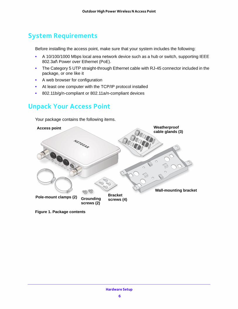
Your package contains the following items.
Wall-mounting bracketBracketPole-mount clamps (2)
WeatherproofAccess pointcable glands (3)
Groundingscrews (2)
screws (4)
Figure 1. Package contents
Hardware Setup
6
Outdoor High Power Wireless N Access Point
Front Panel
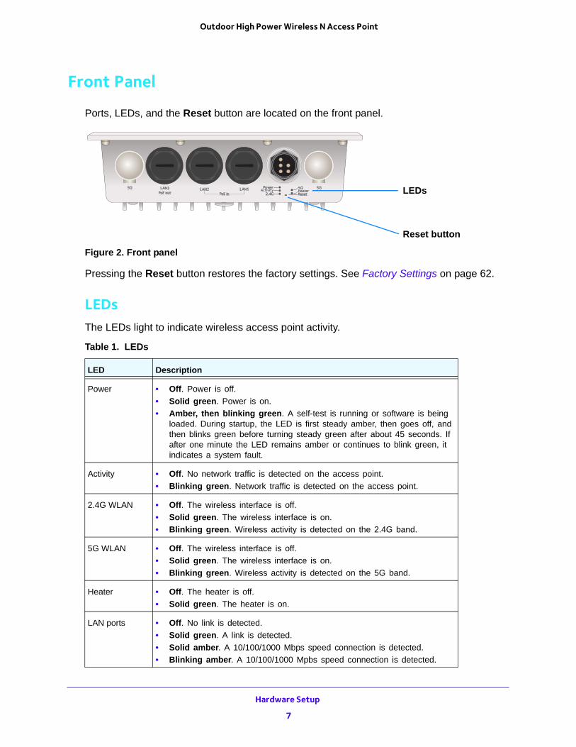
Ports, LEDs, and the Reset button are located on the front panel.
LEDs
Reset button
Figure 2. Front panel
Pressing the Reset button restores the factory settings. See Factory Settings on page 62.
LEDsThe LEDs light to indicate wireless access point activity.
Table 1. LEDs
LED Description
Power • Off. Power is off.
• Solid green. Power is on.
• Amber, then blinking green. A self-test is running or software is being loaded. During startup, the LED is first steady amber, then goes off, and then blinks green before turning steady green after about 45 seconds. If after one minute the LED remains amber or continues to blink green, it indicates a system fault.
Activity • Off. No network traffic is detected on the access point.
• Blinking green. Network traffic is detected on the access point.
2.4G WLAN • Off. The wireless interface is off.
• Solid green. The wireless interface is on.
• Blinking green. Wireless activity is detected on the 2.4G band.
5G WLAN • Off. The wireless interface is off.
• Solid green. The wireless interface is on.
• Blinking green. Wireless activity is detected on the 5G band.
Heater • Off. The heater is off.
• Solid green. The heater is on.
LAN ports • Off. No link is detected.
• Solid green. A link is detected.
• Solid amber. A 10/100/1000 Mbps speed connection is detected.
• Blinking amber. A 10/100/1000 Mpbs speed connection is detected.
Hardware Setup
7
Outdoor High Power Wireless N Access Point
Product Label
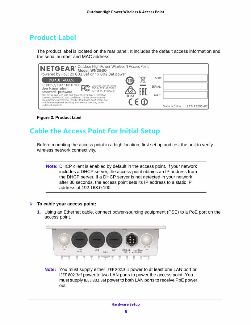
The product label is located on the rear panel. It includes the default access information and the serial number and MAC address.
Figure 3. Product label
Cable the Access Point for Initial Setup
Before mounting the access point in a high location, first set up and test the unit to verify wireless network connectivity.
Note: DHCP client is enabled by default in the access point. If your network includes a DHCP server, the access point obtains an IP address from the DHCP server. If a DHCP server is not detected in your network after 30 seconds, the access point sets its IP address to a static IP address of 192.168.0.100.
To cable your access point:
1. Using an Ethernet cable, connect power-sourcing equipment (PSE) to a PoE port on the access point.
Note: You must supply either IEEE 802.3at power to at least one LAN port or IEEE 802.3af power to two LAN ports to power the access point. You must supply IEEE 802.3at power to both LAN ports to receive PoE power out.
Hardware Setup
8

Outdoor High Power Wireless N Access Point
2. If a DHCP server is not connected to your network, configure a computer with a static IP address of 192.168.0.210 and a subnet mask of 255.255.255.0.
3. Connect an Ethernet cable from a LAN port on the access point to a LAN port on the computer.
4. Check the LEDs to verify that the access point is set up correctly.
Hardware Setup
9
2
2. Initial SetupThis chapter covers the following topics:
• Connect to the Access Point and Log In
• Specify the Access Point Name and Location
• Set the Time
• Configure the Basic IP Settings
• Configure the Access Point as a DHCP Server for Wireless Clients
• Configure the Basic Wireless Settings
• Turn On the Wireless Signal and Test Connectivity
• Plan Your Network Security
• Set Up Security Profiles
• Deploy the Access Point
• Connect Optional External Antennas
10
Outdoor High Power Wireless N Access Point
Connect to the Access Point and Log In
You can connect to the access point’s web management interface to view or change its settings.
To connect to the access point:
1. If a DHCP server is not connected to your network, configure a computer with a static IP address of 192.168.0.210 and a subnet mask of 255.255.255.0.
2. Connect an Ethernet cable from a LAN port on the access point to a LAN port on the computer.
During initial setup, use a wired Ethernet connection.
3. Launch a web browser.
4. In the address field of the browser, enter http://192.168.0.100.
A login screen displays.
5. Enter admin for the user name and password for the password.
The user name and password are case-sensitive.
The web management interface of the access point displays the General screen.
Specify the Access Point Name and Location
You must use a computer that is configured with a static IP address of 192.168.0.210 and a subnet mask of 255.255.255.0. During initial setup, use a wired Ethernet connection from the computer to the access point.
To specify the access point name and location:
1. Launch a web browser on the computer that is connected to the access point.
2. In the address field of the browser, enter http://192.168.0.100.
A login prompt displays.
3. Enter the user name and password.
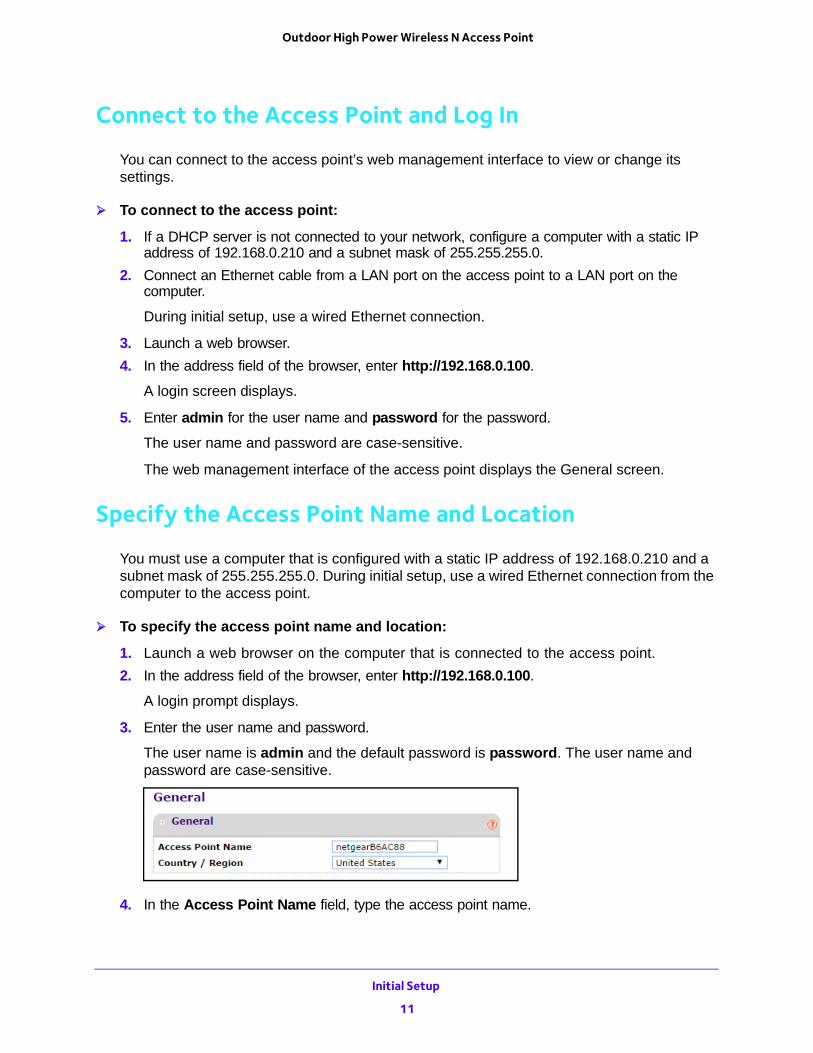
The user name is admin and the default password is password. The user name and password are case-sensitive.
4. In the Access Point Name field, type the access point name.
Initial Setup
11
Outdoor High Power Wireless N Access Point
This unique name is the access point NetBIOS name. The default access point name is on the product label. The naming convention is netgearxxxxxx, where xxxxxxx represents the last 6 digits of the access point MAC address. You can enter a unique name up to 15 characters long.
5. From the Country/Region list, select the region where the access point is located.
In the United States this setting cannot be changed. If your country or region is not listed, check with NETGEAR support for the correct selection.
6. Click the Apply button at the bottom of the screen.
Your settings are saved.
Set the Time
You must use a computer that is configured with a static IP address of 192.168.0.210 and a subnet mask of 255.255.255.0. During initial setup, use a wired Ethernet connection from the computer to the access point.
To set the time:
1. Launch a web browser on the computer that is connected to the access point.
2. In the address field of the browser, enter http://192.168.0.100.
A login prompt displays.
3. Enter the user name and password.
The user name is admin and the default password is password. The user name and password are case-sensitive.
The General screen displays.
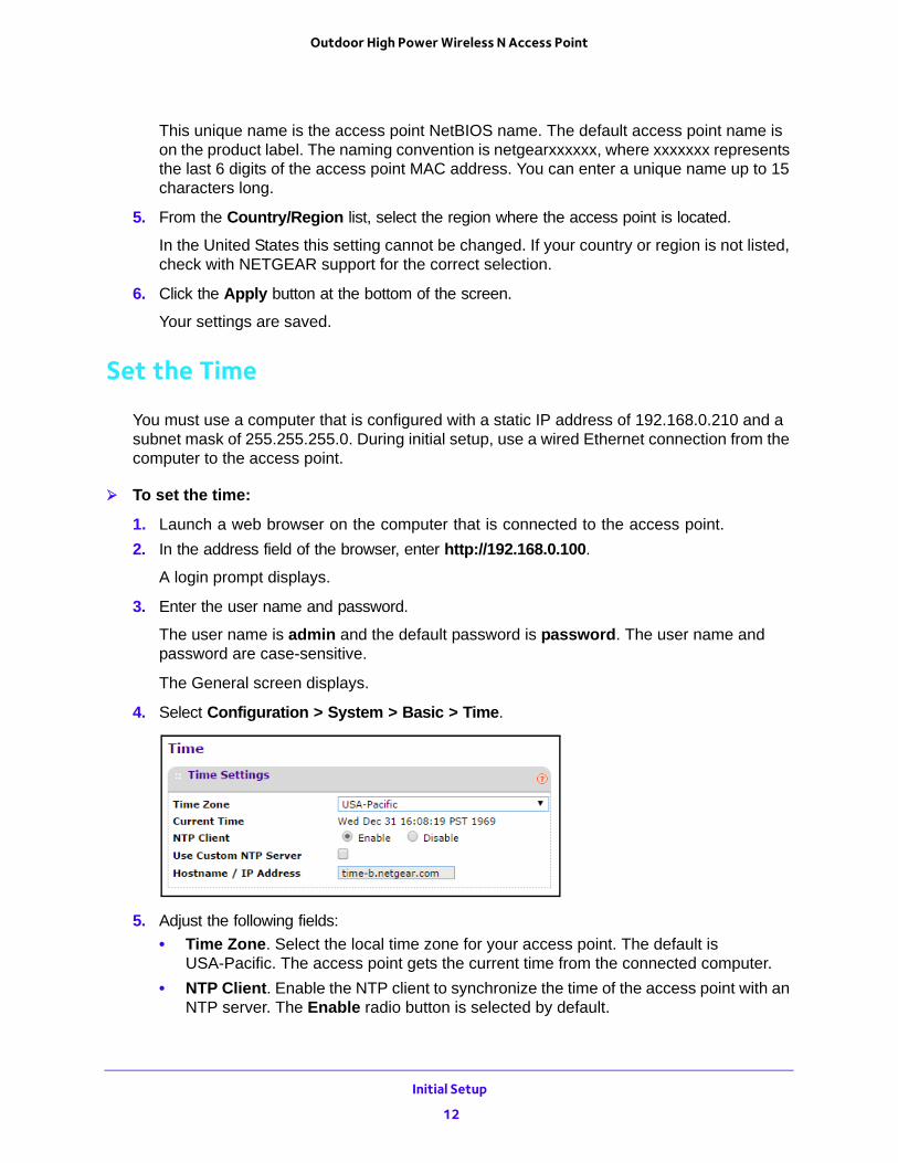
4. Select Configuration > System > Basic > Time.
5. Adjust the following fields:
• Time Zone. Select the local time zone for your access point. The default is USA-Pacific. The access point gets the current time from the connected computer.
• NTP Client. Enable the NTP client to synchronize the time of the access point with an NTP server. The Enable radio button is selected by default.
Initial Setup
12
Outdoor High Power Wireless N Access Point
Note: You need an Internet connection to get the current time using an NTP client.
• Use Custom NTP Server. Select this check box if you use a custom NTP server. The check box is cleared by default.
• Hostname / IP Address. Enter the host name or the IP address of the custom NTP server. The default is time-b.netgear.com.
6. Click the Apply button at the bottom of the screen.
Your settings are saved.
Configure the Basic IP Settings
The default settings work in most cases, but you can change them as needed if your access point is part of a complex LAN network.
You must use a computer that is configured with a static IP address of 192.168.0.210 and a subnet mask of 255.255.255.0. During initial setup, use a wired Ethernet connection from the computer to the access point.
To configure the basic IP settings:
1. Launch a web browser on the computer that is connected to the access point.
2. In the address field of the browser, enter http://192.168.0.100.
A login prompt displays.
3. Enter the user name and password.
The user name is admin and the default password is password.
The General screen displays.
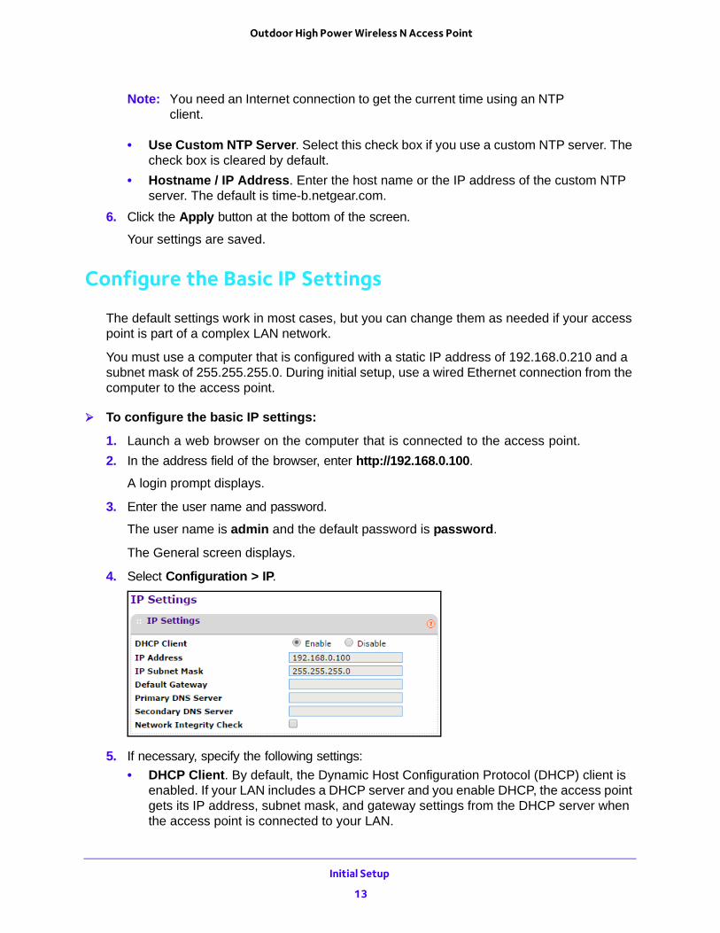
4. Select Configuration > IP.
5. If necessary, specify the following settings:
• DHCP Client. By default, the Dynamic Host Configuration Protocol (DHCP) client is enabled. If your LAN includes a DHCP server and you enable DHCP, the access point gets its IP address, subnet mask, and gateway settings from the DHCP server when the access point is connected to your LAN.
Initial Setup
13
Outdoor High Power Wireless N Access Point
• IP Address. The IP address of your access point. The default IP address is 192.168.0.100 when it does not get a dynamic IP address. To change it, enter an unused IP address from the address range used on your LAN, or enable DHCP in a network with a DHCP server.
• IP Subnet Mask. The access point calculates the subnet mask based on the IP address that you assign. Otherwise, you can use 255.255.255.0 (the default) as the subnet mask.
• Default Gateway. The IP address of the gateway for your LAN. For more complex networks, enter the address of the router for the network segment to which the access point is connected.
• Primary DNS Server. The IP address for the primary Domain Name Server used by stations on your LAN.
• Secondary DNS Server.The IP address for the secondary Domain Name Server used by stations on your LAN.
• Network Integrity Check. Select this check box to enable the access point to validate that the upstream link is active before allowing wireless associations. If you set this option you must ensure that your default gateway is configured.
6. Click the Apply button at the bottom of the screen.
Your settings are saved.
If you changed the subnet of the LAN IP address, you are disconnected from the access point user interface. To reconnect, reconfigure your computer with a static IP address within the new LAN IP subnet.
Configure the Access Point as a DHCP Server for Wireless Clients
Your access point comes with a built-in DHCP server for wireless clients only, which can be especially useful in small networks. You can enable and configure the DHCP server. The access point will provide TCP/IP configuration for all wireless stations connected to it.
To configure the access point as a DHCP server for wireless clients:
1. Launch a web browser on the computer that is connected to the access point.
2. In the address field of the browser, enter http://192.168.0.100.
A login prompt displays.
3. Enter the user name and password.
The user name is admin and the default password is password.
The General screen displays.
Initial Setup
14
Outdoor High Power Wireless N Access Point
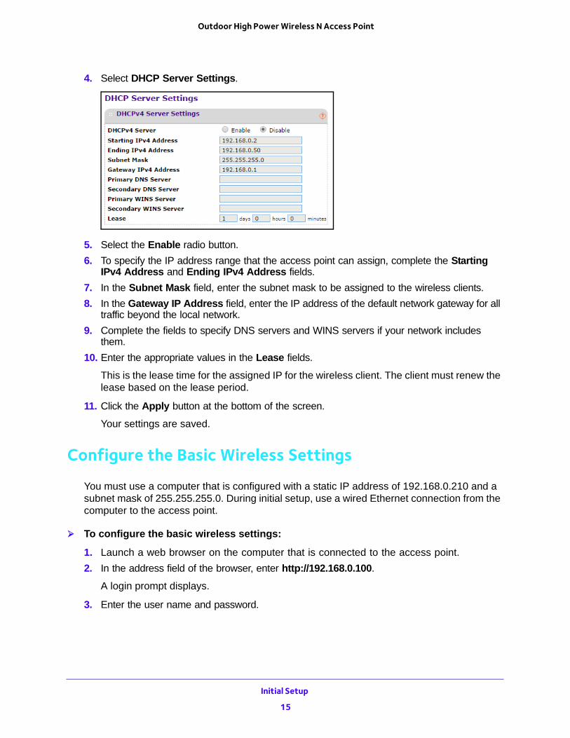
4. Select DHCP Server Settings.
5. Select the Enable radio button.
6. To specify the IP address range that the access point can assign, complete the Starting IPv4 Address and Ending IPv4 Address fields.
7. In the Subnet Mask field, enter the subnet mask to be assigned to the wireless clients.
8. In the Gateway IP Address field, enter the IP address of the default network gateway for all traffic beyond the local network.
9. Complete the fields to specify DNS servers and WINS servers if your network includes them.
10. Enter the appropriate values in the Lease fields.
This is the lease time for the assigned IP for the wireless client. The client must renew the lease based on the lease period.
11. Click the Apply button at the bottom of the screen.
Your settings are saved.
Configure the Basic Wireless Settings
You must use a computer that is configured with a static IP address of 192.168.0.210 and a subnet mask of 255.255.255.0. During initial setup, use a wired Ethernet connection from the computer to the access point.
To configure the basic wireless settings:
1. Launch a web browser on the computer that is connected to the access point.
2. In the address field of the browser, enter http://192.168.0.100.
A login prompt displays.
3. Enter the user name and password.
Initial Setup
15
Outdoor High Power Wireless N Access Point
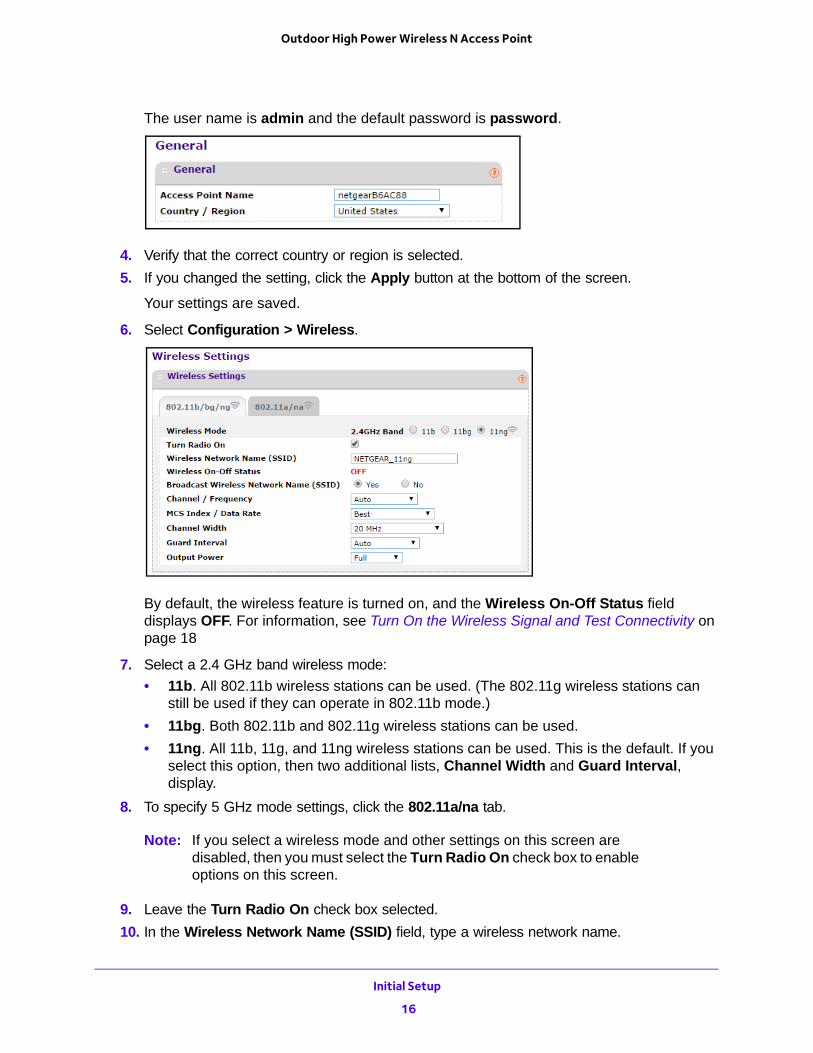
The user name is admin and the default password is password.
4. Verify that the correct country or region is selected.
5. If you changed the setting, click the Apply button at the bottom of the screen.
Your settings are saved.
6. Select Configuration > Wireless.
By default, the wireless feature is turned on, and the Wireless On-Off Status field displays OFF. For information, see Turn On the Wireless Signal and Test Connectivity on page 18
7. Select a 2.4 GHz band wireless mode:
• 11b. All 802.11b wireless stations can be used. (The 802.11g wireless stations can still be used if they can operate in 802.11b mode.)
• 11bg. Both 802.11b and 802.11g wireless stations can be used.
• 11ng. All 11b, 11g, and 11ng wireless stations can be used. This is the default. If you select this option, then two additional lists, Channel Width and Guard Interval, display.
8. To specify 5 GHz mode settings, click the 802.11a/na tab.
Note: If you select a wireless mode and other settings on this screen are disabled, then you must select the Turn Radio On check box to enable options on this screen.
9. Leave the Turn Radio On check box selected.
10. In the Wireless Network Name (SSID) field, type a wireless network name.
Initial Setup
16
Outdoor High Power Wireless N Access Point
This is the name of your wireless network. It is set to the default name of NETGEAR_11na for 802.11a/n wireless mode and NETGEAR_11ng for 802.11b/g/n wireless mode.
Note: The SSID of any wireless client must match the SSID you configured in the access point. If they do not match, you cannot get a wireless connection.
11. Leave the Broadcast Wireless Network Name (SSID) Yes radio button selected.
If you disable broadcast of the SSID, only devices that use the correct SSID can connect. This nullifies the wireless network discovery feature of some products such as Windows 7, but the data is still fully exposed to a determined snoop using specialized test equipment like wireless sniffers. By default, the Yes radio button is selected.
12. In the Channel / Frequency list, leave Auto selected.
When Auto is selected, the access point seledcts a channel with the least interference.
Do not change the wireless channel unless you experience interference (shown by lost connections or slow data transfers). If this happens, you might need to experiment with different channels to see which is the best. When selecting or changing channels, bear these points in mind:
• Access points use a fixed channel. You can select the channel used. This allows you to select a channel that provides the least interference and best performance.
• If you use multiple access points, it is better if adjacent access points use different channels to reduce interference. NETGEAR recommends channel spacing between adjacent access points of 5 channels (for example, use Channels 1 and 6, or 6 and 11).
• Wireless stations usually scan all channels, looking for an access point. If more than one access point can be used, the one with the strongest signal is used. This can happen only when the access points use the same SSID.
Note: If you use wireless bridging and repeating, you must select a specific channel for your network. For more information, see Wireless Bridging and Repeating on page 37.
13. From the list, select the MCS Index/Data Rate.
This is the transmit data rate of the wireless network. Depending on the band selected, the set of rates varies. When the auto channel is enabled in the 802.11ng mode, then the default channel width mode is 20 MHz. For information about the supported data rates, see Technical Specifications on page 65.
14. Specify the channel width.
A wider channel improves the performance, but some legacy devices can operate only on either 20 MHz or 40 MHz. In the Channel Width list, the following options are available:
• 20 MHz. This is the static, legacy mode. It gives the least throughput.
Initial Setup
17
Outdoor High Power Wireless N Access Point
• 40 MHz. This is the static, high-throughput mode. Legacy clients cannot connect in this mode.
• 20/40 MHz. This is the dynamic compatibility mode. Legacy clients can connect to 20 MHz and 11n clients can connect to 40 MHz.
15. From the list, select the guard Interval.
The guard interval protects from interference from other transmissions. The default is Auto.
16. In the Output Power list, select the transmit power of the access point.
The options are Full, Half, Quarter, Eighth, and Minimum. Decrease the transmit power if two or more access points are close together and use the same channel frequency. The default is Full. The transmit power might vary depending on the local regulatory regulations.
17. Click the Apply button at the bottom of the screen.
Your settings are saved.
Turn On the Wireless Signal and Test Connectivity
By default, the access point wireless signal is off. After you configure the basic wireless settings, turn on the wireless signal and verify that wireless clients can connect.
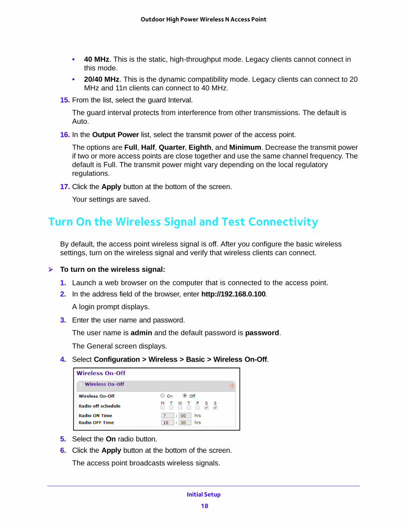
To turn on the wireless signal:
1. Launch a web browser on the computer that is connected to the access point.
2. In the address field of the browser, enter http://192.168.0.100.
A login prompt displays.
3. Enter the user name and password.
The user name is admin and the default password is password.
The General screen displays.
4. Select Configuration > Wireless > Basic > Wireless On-Off.
5. Select the On radio button.
6. Click the Apply button at the bottom of the screen.
The access point broadcasts wireless signals.
Initial Setup
18
Outdoor High Power Wireless N Access Point
7. Verify that your wireless clients can connect to the access point.
When wireless connectivity is working, configure wireless security.
Plan Your Network Security
To prevent unauthorized access to your network, NETGEAR recommends that you use the security features of your wireless equipment. You can enhance the security of your wireless network in several ways:
• Use the WPA2 or Mixed WPA/WPA2 security option. A security option is the type of security protocol applied to your wireless network. The security protocol encrypts data transmissions and ensures that only trusted devices receive authorization to connect to your network. Several types of encryption are available: Wi-Fi Protected Access II (WPA2), WPA, and Wired Equivalent Privacy (WEP).
- WPA2 is the latest and most secure. NETGEAR recommends that you use this option if your equipment supports it.
- WEP and TKIP provide only legacy (slower) rates of operation. NETGEAR recommends AES encryption so that you can use the 11n rates and speed.
For more information, see Set Up Security Profiles on page 20.
• Keep watch over your wireless network. Regularly monitor the wireless stations that are allowed to connect to your access point and make sure that all of them are legitimate. For more information, see View Wireless Stations on page 53.
• Change the login password regularly. When you use the default login password, an intruder can more easily figure out how to log in to the management interface of the access point and change the settings. For more information, see Change the admin Password on page 44.
Note: For additional wireless security, you can change the default network key regularly. But whenever you change the network key, you must reconnect all of the wireless devices. For more information, see Set Up Security Profiles on page 20.
• Turn off the wireless radio. During the hours when your offices are closed, turn off the wireless radio. For more information, see Set Up a Schedule for the Wireless Radios on page 27.
• Turn off the broadcast of the wireless network name (SSID). If you disable broadcast of the SSID, only devices that use the correct SSID can connect. This nullifies the wireless network discovery feature of some products such as Windows XP, but the data is still fully exposed to a determined snoop using specialized test equipment like wireless sniffers. For more information, see Set Up Security Profiles on page 20.
• Restrict access based on MAC address. You can restrict access to only trusted computers so that unknown computers cannot connect wirelessly to the access point.
Initial Setup
19
Outdoor High Power Wireless N Access Point
MAC address filtering adds an obstacle against unwanted access to your network. For more information, see Configure MAC Authentication on page 28.
Set Up Security Profiles
Details of each wireless network are contained in a security profile. Each security profile contains the following information:
• Profile name. This is the unique profile name. This value can be up to 32 alphanumeric characters.
• SSID. This is the SSID associated with this profile.
• Security. This is the security standard, such as WPA2-PSK, that is associated with the profile.
To change security profiles, you must use a computer that is configured with a static IP address of 192.168.0.210 and a subnet mask of 255.255.255.0. During initial setup, use a wired Ethernet connection from the computer to the access point.
To edit the security profile settings:
1. Launch a web browser on the computer that is connected to the access point.
2. In the address field of the browser, enter http://192.168.0.100.
A login prompt displays.
3. Enter the user name and password.
The user name is admin and the default password is password.
The General screen displays.
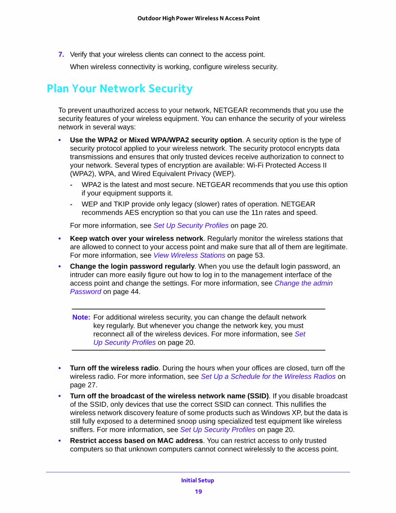
4. Select Configuration > Security.
For initial configuration and testing, the Security field for Profile 1 (the default profile) is set to Open System and the SSIDs are set to NETGEAR_11ng and NETGEAR_11na.
Note: The SSID of any wireless client must match the SSID you configured in the access point. If they do not match, you cannot get a wireless connection.
Initial Setup
20
Outdoor High Power Wireless N Access Point
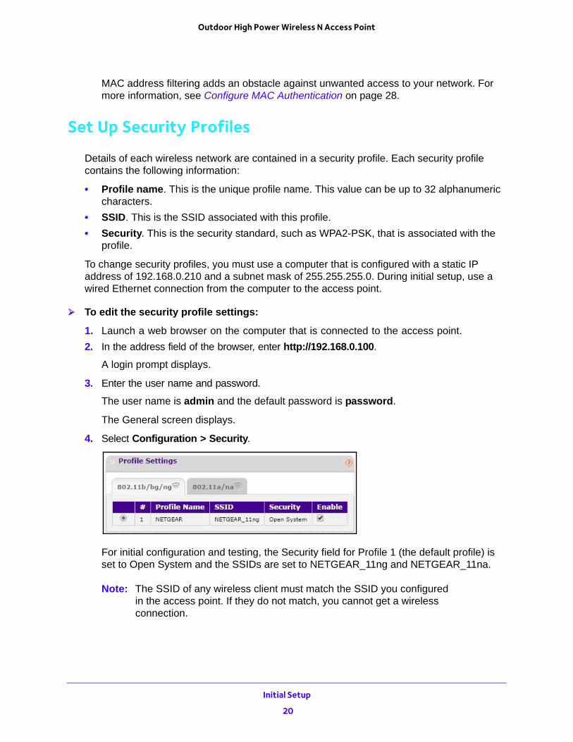
5. Select the profile that you want to change and click the Edit button at the bottom of the screen.
The fields that display depend on the security settings.
6. To change the wireless network name, in the WIreless Network Name (SSID) field, enter the new wireless network name.
7. To broadcast the wireless network name, select the Broadcast Wireless Network Name (SSID) Yes radio button.
8. In the Network Authentication list, select the authentication type:
• Open System. This selection can be used with WEP encryption or no encryption.
• WPA2-PSK. Select this option only if all clients support WPA2. If you select this option, you must use AES and TKIP + AES encryption and enter the WPA passphrase (network key).
• Mixed WPA/WPA2-PSK. This selection allows clients to use either WPA (with TKIP) or WPA2 (with AES). If you select this option, you must use TKIP + AES encryption and enter the WPA passphrase (network key).
9. In the Data Encryption list, select the data encryption type.
The options available for data encryption depend on the option you select in the Network Authentication list. Select one of the following:
• None. No encryption is used.
• 64 bits WEP. This is standard WEP 40/64-bit encryption.
• 128 bits WEP. This is standard WP 104/128-bit encryption.
• 152 bits WEP. This is a proprietary mode, that works only with other wireless devices that support this mode.
• AES. This is the standard encryption method for WPA2. Some clients support AES with WPA, but this access point does not.
• TKIP + AES. This setting supports both WPA and WPA2. Broadcast packets use TKIP. For unicast (point-to-point) transmissions, WPA clients use TKIP, and WPA2 clients use AES.
10. To prevent associated wireless clients from communicating with each other, select Enable in the Wireless Client Security Separation list.
This feature is intended for hotspots and other public access situations.
Initial Setup
21
Outdoor High Power Wireless N Access Point
11. Click the Apply button at the bottom of the screen.
Your settings are saved.
12. Verify that your wireless clients can connect to the access point with the appropriate security settings.
Deploy the Access Point
Before mounting the access point in a high location, first set up and test the access point to verify wireless network connectivity.
By default, the DHCP client is enabled in the access point. If your network uses static IP addresses, you must change this setting. To connect to the access point after the DHCP server on your network assigns it a new IP address, enter the access point name in your web browser. The default name is netgearxxxxxx, where xxxxxx represents the last 6 digits of the MAC address. The default name is printed on the product label.
The best location for your access point is elevated, at the center of your wireless coverage area, and within line of sight of all mobile devices.
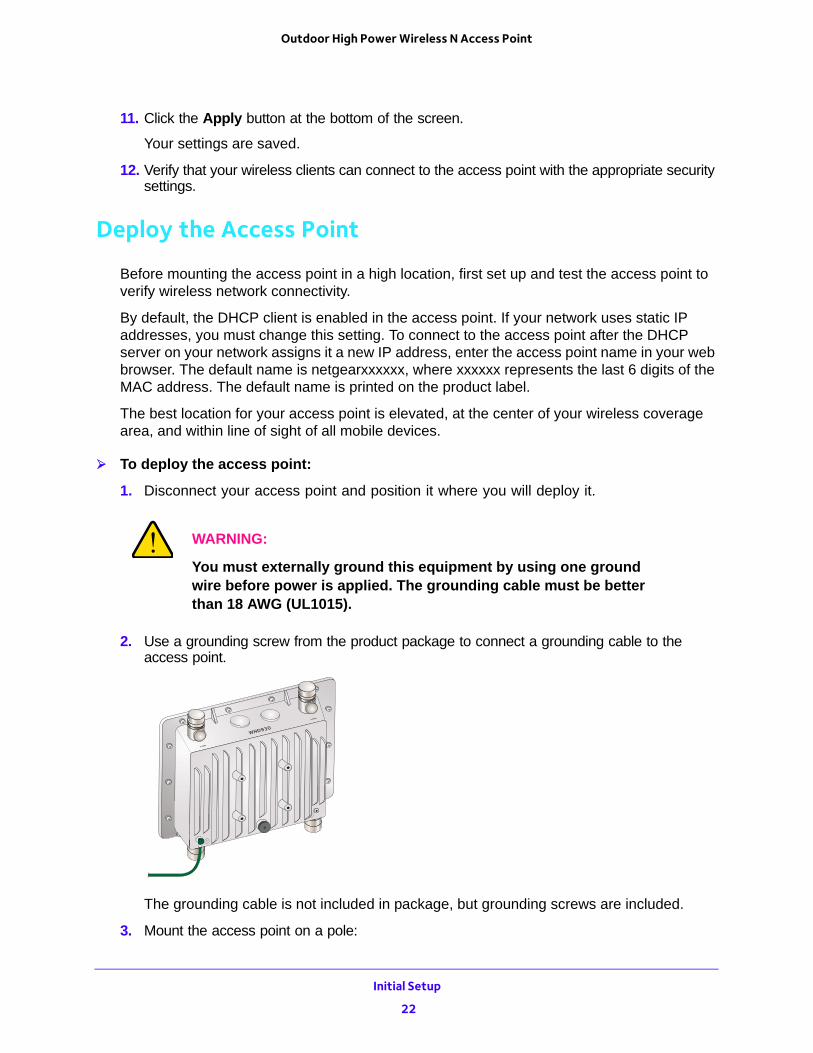
To deploy the access point:
1. Disconnect your access point and position it where you will deploy it.
WARNING:
You must externally ground this equipment by using one ground wire before power is applied. The grounding cable must be better than 18 AWG (UL1015).
2. Use a grounding screw from the product package to connect a grounding cable to the access point.
The grounding cable is not included in package, but grounding screws are included.
3. Mount the access point on a pole:
Initial Setup
22
Outdoor High Power Wireless N Access Point
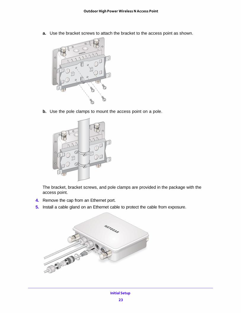
a. Use the bracket screws to attach the bracket to the access point as shown.
b. Use the pole clamps to mount the access point on a pole.
The bracket, bracket screws, and pole clamps are provided in the package with the access point.
4. Remove the cap from an Ethernet port.
5. Install a cable gland on an Ethernet cable to protect the cable from exposure.
Initial Setup
23
Outdoor High Power Wireless N Access Point
6. Connect the Ethernet cable from the access point to a LAN port on your router, switch or hub.
7. Connect a power sourcing equipment (PSE) to one of the PoE ports on the access point, using a cable gland to protect the Ethernet cable.
If your router switch or hub supplies PoE, skip this step.
Note: You must supply either IEEE 802.3at power to at least one LAN port or IEEE 802.3af power to two LAN ports to power the access point. You must supply IEEE 802.3at power to both LAN ports to receive PoE power out.
8. Using a wireless device, verify connectivity by using a browser to connect to the Internet.
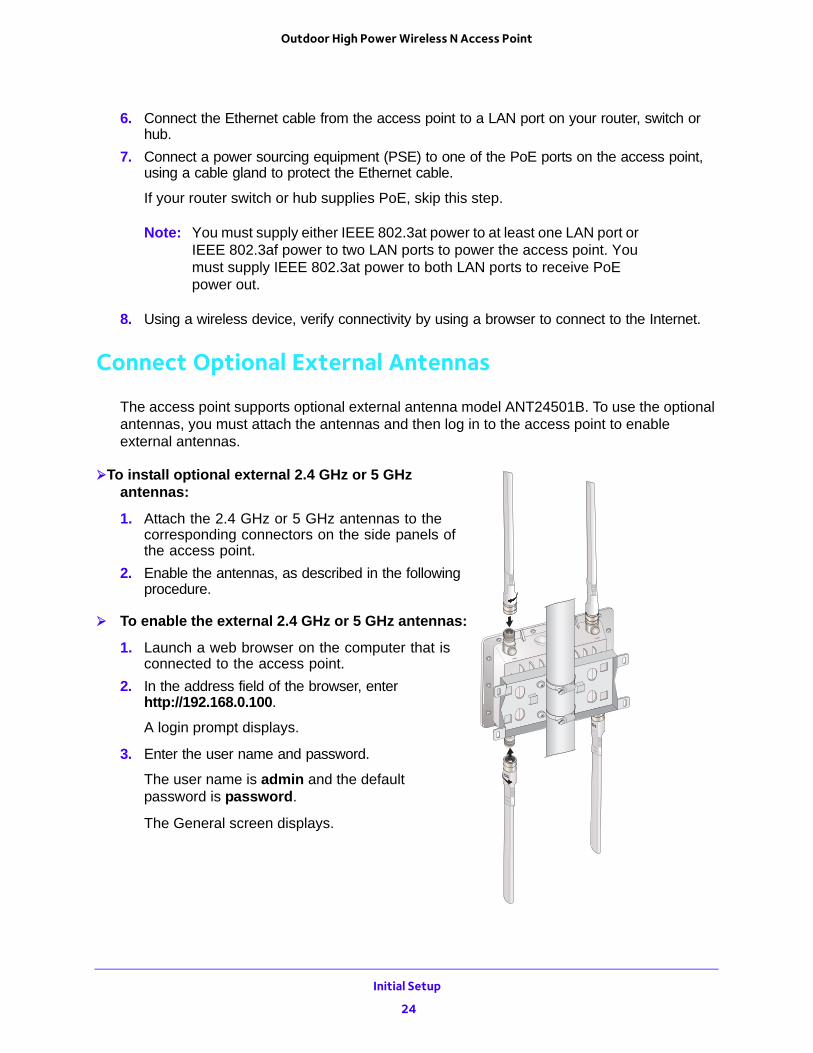
Connect Optional External Antennas
The access point supports optional external antenna model ANT24501B. To use the optional antennas, you must attach the antennas and then log in to the access point to enable external antennas.
To install optional external 2.4 GHz or 5 GHz antennas:
1. Attach the 2.4 GHz or 5 GHz antennas to the corresponding connectors on the side panels of the access point.
2. Enable the antennas, as described in the following procedure.
To enable the external 2.4 GHz or 5 GHz antennas:
1. Launch a web browser on the computer that is connected to the access point.
2. In the address field of the browser, enter http://192.168.0.100.
A login prompt displays.
3. Enter the user name and password.
The user name is admin and the default password is password.
The General screen displays.
Initial Setup
24
Outdoor High Power Wireless N Access Point
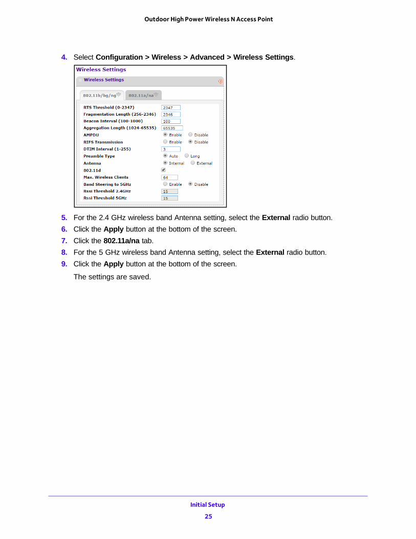
4. Select Configuration > Wireless > Advanced > Wireless Settings.
5. For the 2.4 GHz wireless band Antenna setting, select the External radio button.
6. Click the Apply button at the bottom of the screen.
7. Click the 802.11a/na tab.
8. For the 5 GHz wireless band Antenna setting, select the External radio button.
9. Click the Apply button at the bottom of the screen.
The settings are saved.
Initial Setup
25
3
3. Network SettingsThis chapter covers the following topics:
• Spanning Tree Protocol
• Set Up a Schedule for the Wireless Radios
• Configure MAC Authentication
• Configure RADIUS Authentication
• Configure Advanced Wireless Settings
• Quality of Service Settings
• Wireless Bridging and Repeating
• Disable Ethernet LLDP
26
Outdoor High Power Wireless N Access Point
Spanning Tree Protocol
By default, Spanning Tree Protocol is disabled.
To enable or disable Spanning Tree Protocol:
1. Launch a web browser on the computer that is connected to the access point.
2. In the address field of the browser, enter http://192.168.0.100.
A login prompt displays.
3. Enter the user name and password.
The user name is admin and the default password is password.
The General screen displays.
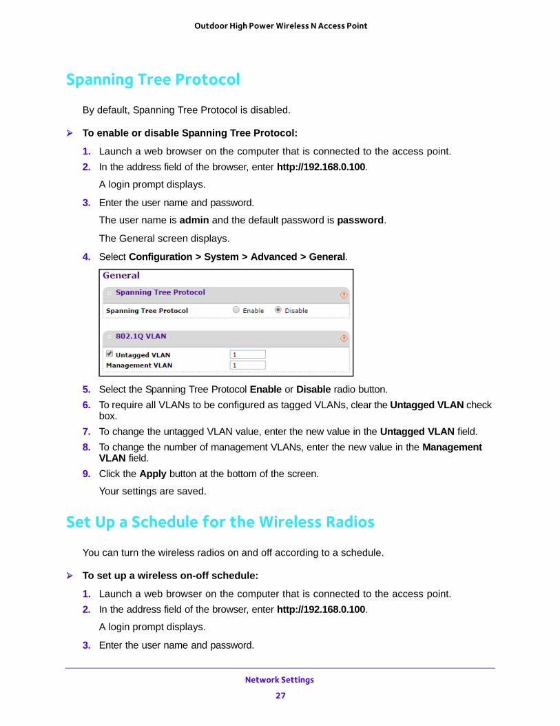
4. Select Configuration > System > Advanced > General.
5. Select the Spanning Tree Protocol Enable or Disable radio button.
6. To require all VLANs to be configured as tagged VLANs, clear the Untagged VLAN check box.
7. To change the untagged VLAN value, enter the new value in the Untagged VLAN field.
8. To change the number of management VLANs, enter the new value in the Management VLAN field.
9. Click the Apply button at the bottom of the screen.
Your settings are saved.
Set Up a Schedule for the Wireless Radios
You can turn the wireless radios on and off according to a schedule.
To set up a wireless on-off schedule:
1. Launch a web browser on the computer that is connected to the access point.
2. In the address field of the browser, enter http://192.168.0.100.
A login prompt displays.
3. Enter the user name and password.
Network Settings
27
Outdoor High Power Wireless N Access Point
The user name is admin and the default password is password.
The General screen displays.
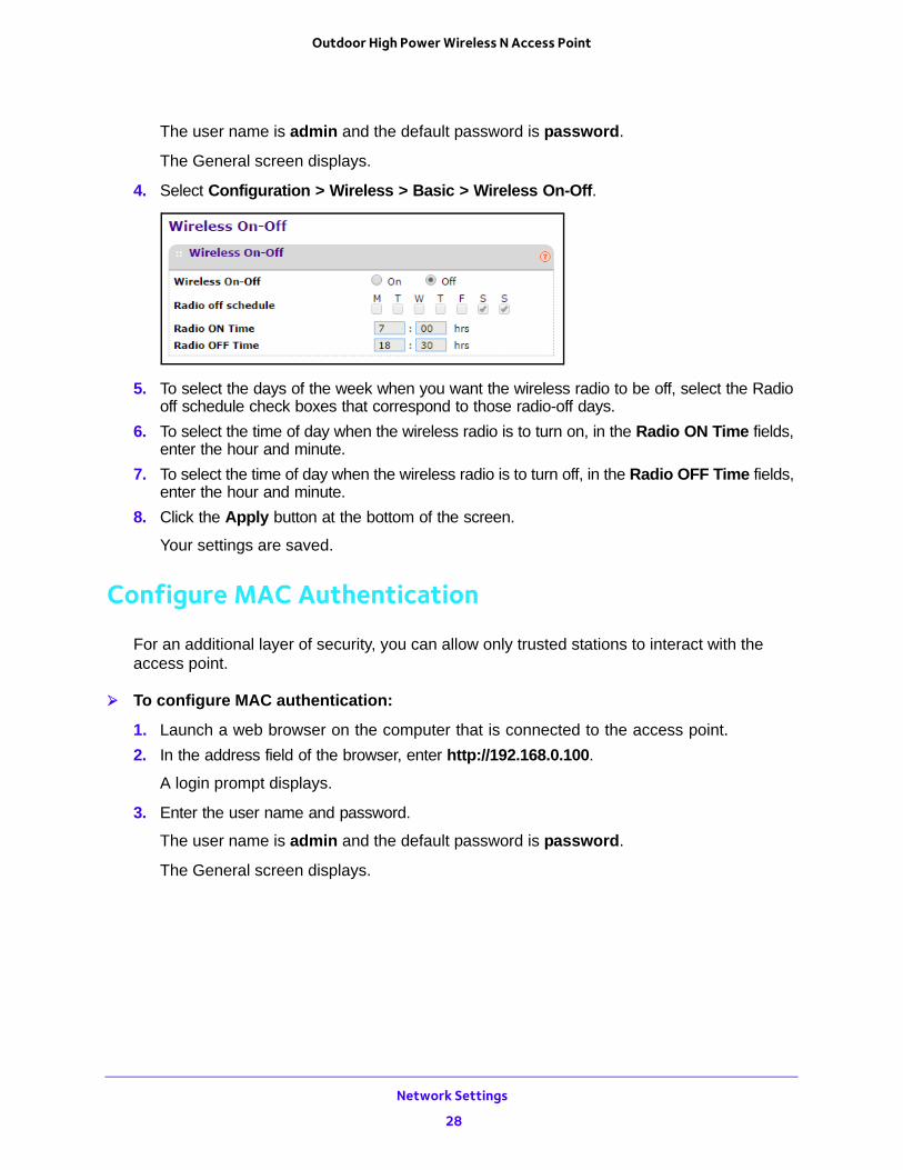
4. Select Configuration > Wireless > Basic > Wireless On-Off.
5. To select the days of the week when you want the wireless radio to be off, select the Radio off schedule check boxes that correspond to those radio-off days.
6. To select the time of day when the wireless radio is to turn on, in the Radio ON Time fields, enter the hour and minute.
7. To select the time of day when the wireless radio is to turn off, in the Radio OFF Time fields, enter the hour and minute.
8. Click the Apply button at the bottom of the screen.
Your settings are saved.
Configure MAC Authentication
For an additional layer of security, you can allow only trusted stations to interact with the access point.
To configure MAC authentication:
1. Launch a web browser on the computer that is connected to the access point.
2. In the address field of the browser, enter http://192.168.0.100.
A login prompt displays.
3. Enter the user name and password.
The user name is admin and the default password is password.
The General screen displays.
Network Settings
28
Outdoor High Power Wireless N Access Point
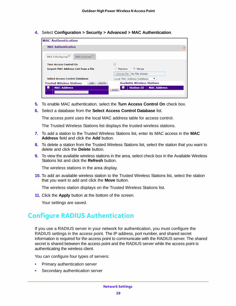
4. Select Configuration > Security > Advanced > MAC Authentication.
5. To enable MAC authentication, select the Turn Access Control On check box.
6. Select a database from the Select Access Control Database list.
The access point uses the local MAC address table for access control.
The Trusted Wireless Stations list displays the trusted wireless stations.
7. To add a station to the Trusted Wireless Stations list, enter its MAC access in the MAC Address field and click the Add button.
8. To delete a station from the Trusted Wireless Stations list, select the station that you want to delete and click the Delete button.
9. To view the available wireless stations in the area, select check box in the Available Wireless Stations list and click the Refresh button.
The wireless stations in the area display.
10. To add an available wireless station to the Trusted Wireless Stations list, select the station that you want to add and click the Move button.
The wireless station displays on the Trusted Wireless Stations list.
11. Click the Apply button at the bottom of the screen.
Your settings are saved.
Configure RADIUS Authentication
If you use a RADIUS server in your network for authentication, you must configure the RADIUS settings in the access point. The IP address, port number, and shared secret information is required for the access point to communicate with the RADIUS server. The shared secret is shared between the access point and the RADIUS server while the access point is authenticating the wireless client.
You can configure four types of servers:
• Primary authentication server
• Secondary authentication server
Network Settings
29
Outdoor High Power Wireless N Access Point
• Primary accounting server
• Secondary accounting server
The primary servers are used by default. If the primary server fails, the secondary server is used if it is configured.
To configure RADIUS server settings:
1. Launch a web browser on the computer that is connected to the access point.
2. In the address field of the browser, enter http://192.168.0.100.
A login prompt displays.
3. Enter the user name and password.
The user name is admin and the default password is password.
The General screen displays.
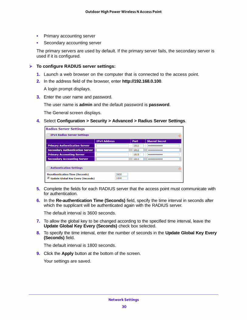
4. Select Configuration > Security > Advanced > Radius Server Settings.
5. Complete the fields for each RADIUS server that the access point must communicate with for authentication.
6. In the Re-authentication Time (Seconds) field, specify the time interval in seconds after which the supplicant will be authenticated again with the RADIUS server.
The default interval is 3600 seconds.
7. To allow the global key to be changed according to the specified time interval, leave the Update Global Key Every (Seconds) check box selected.
8. To specify the time interval, enter the number of seconds in the Update Global Key Every (Seconds) field.
The default interval is 1800 seconds.
9. Click the Apply button at the bottom of the screen.
Your settings are saved.
Network Settings
30
Outdoor High Power Wireless N Access Point
Configure Advanced Wireless Settings
The default settings usually work well. However, you can adjust these settings to fine-tune the performance of your access point for your environment.
To configure advanced wireless settings:
1. Launch a web browser on the computer that is connected to the access point.
2. In the address field of the browser, enter http://192.168.0.100.
A login prompt displays.
3. Enter the user name and password.
The user name is admin and the default password is password.
The General screen displays.
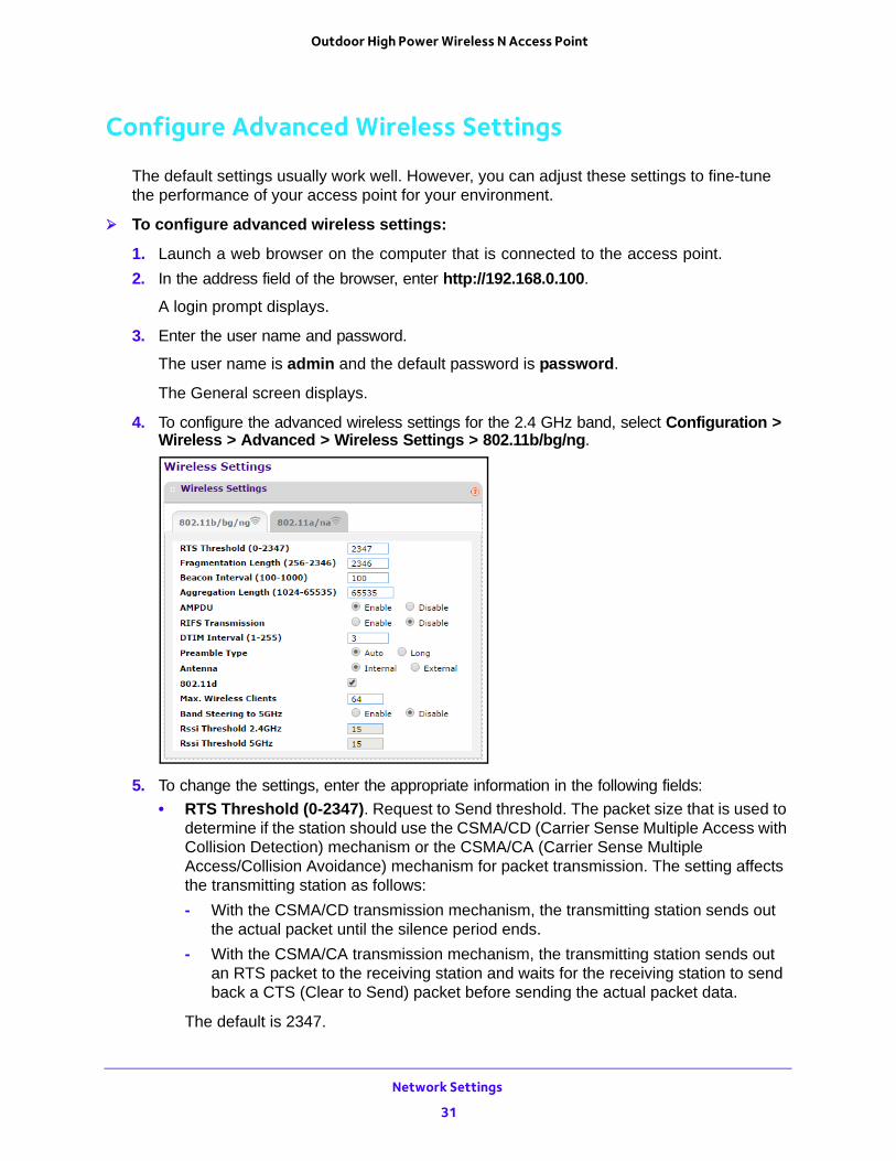
4. To configure the advanced wireless settings for the 2.4 GHz band, select Configuration > Wireless > Advanced > Wireless Settings > 802.11b/bg/ng.
5. To change the settings, enter the appropriate information in the following fields:
• RTS Threshold (0-2347). Request to Send threshold. The packet size that is used to determine if the station should use the CSMA/CD (Carrier Sense Multiple Access with Collision Detection) mechanism or the CSMA/CA (Carrier Sense Multiple Access/Collision Avoidance) mechanism for packet transmission. The setting affects the transmitting station as follows:
- With the CSMA/CD transmission mechanism, the transmitting station sends out the actual packet until the silence period ends.
- With the CSMA/CA transmission mechanism, the transmitting station sends out an RTS packet to the receiving station and waits for the receiving station to send back a CTS (Clear to Send) packet before sending the actual packet data.
The default is 2347.
Network Settings
31
Outdoor High Power Wireless N Access Point
• Fragmentation Length (256-2346). This is the maximum packet size. Packets larger than the size specified in this field are fragmented. The Fragmentation Length value must be larger than the RTS Threshold value. The default is 2346.
• Beacon Interval (100-1000). The time interval between 100 ms and 1000 ms for each beacon transmission, which allows the access point to synchronize the wireless network. The default is 100.
• Aggregation Length (1024-65535). The aggregation length defines the size of aggregated packets. Larger aggregation lengths can sometimes lead to better network performance. The default is 65535.
• AMPDU. Aggregated MAC Protocol data unit. Aggregates several MAC frames into a single large frame to achieve higher throughput. The default is enabled.
• RIFS Transmission. Reduced interframe space. RIFS transmissions are shorter than other interframe spaces, and if this feature is enabled, the access point allows transmission of successive frames at different transmit powers. The default is disabled.
• DTIM Interval (1-255). The delivery traffic indication message. Specifies the data beacon rate between 1 and 255. The default is 3.
• Preamble Type. A long transmit preamble can provide a more reliable connection or a slightly longer range. A short transmit preamble gives better performance. The Auto setting automatically handles both long and short preambles. The default is Auto.
• 802.11d. Select this check box to include support for additional regulatory domains that are not in the current standard.
• Max. Wireless Clients. The maximum number of wireless clients that can connect to the access point at one time. The default is 64 per radio.
• Band Steering to 5GHz. Band steering identifies the wireless devices that are capable of operating in both the 2.4 GHz and 5 GHz bands. The access point responds to these devices only on the 5 GHz band and allows the dual-band-capable client to connect to the 5 GHz band rather than the 2.4 GHz band, since more channels and bandwidth are available on the 5 GHz band and using this band causes less interference for users.
• Rssi Threshold 2.4GHz. The minimum RSSI threshold that a client must use to connect to a 2.4 GHz access point.
• Rssi Threshold 5GHz. The minimum RSSI threshold that a client must use to connect to a 5 GHz access point.
Network Settings
32
Outdoor High Power Wireless N Access Point
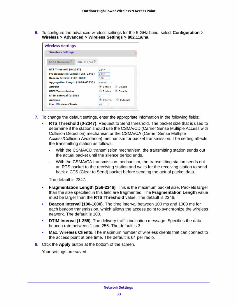
6. To configure the advanced wireless settings for the 5 GHz band, select Configuration > Wireless > Advanced > Wireless Settings > 802.11a/na.
7. To change the default settings, enter the appropriate information in the following fields:
• RTS Threshold (0-2347). Request to Send threshold. The packet size that is used to determine if the station should use the CSMA/CD (Carrier Sense Multiple Access with Collision Detection) mechanism or the CSMA/CA (Carrier Sense Multiple Access/Collision Avoidance) mechanism for packet transmission. The setting affects the transmitting station as follows:
- With the CSMA/CD transmission mechanism, the transmitting station sends out the actual packet until the silence period ends.
- With the CSMA/CA transmission mechanism, the transmitting station sends out an RTS packet to the receiving station and waits for the receiving station to send back a CTS (Clear to Send) packet before sending the actual packet data.
The default is 2347.
• Fragmentation Length (256-2346). This is the maximum packet size. Packets larger than the size specified in this field are fragmented. The Fragmentation Length value must be larger than the RTS Threshold value. The default is 2346.
• Beacon Interval (100-1000). The time interval between 100 ms and 1000 ms for each beacon transmission, which allows the access point to synchronize the wireless network. The default is 100.
• DTIM Interval (1-255). The delivery traffic indication message. Specifies the data beacon rate between 1 and 255. The default is 3.
• Max. Wireless Clients. The maximum number of wireless clients that can connect to the access point at one time. The default is 64 per radio.
8. Click the Apply button at the bottom of the screen.
Your settings are saved.
Network Settings
33
Outdoor High Power Wireless N Access Point
Quality of Service Settings
For most networks, the default QoS (Quality of Service) queue settings work well. You can specify parameters on multiple queues for increased throughput and better performance of differentiated wireless traffic, like VoIP, and other types of audio, video, and streaming media, as well as traditional IP data.
The queues defined for types of data transmitted from access point to station and from station to access point are as follows:
• Data 3 (Voice). Highest-priority queue, minimum delay. Time-sensitive data such as VoIP and streaming media are automatically sent to this queue.
• Data 2 (Video). Highest-priority queue, minimum delay. Time-sensitive video data is automatically sent to this queue.
• Data 1 (Background). Lowest-priority queue, high throughput. Bulk data that requires maximum throughput and is not time-sensitive is sent to this queue (FTP data, for example).
• Data 0 (best effort). Medium-priority queue, medium throughput and delay. Most traditional IP data is sent to this queue.
Enable or Disable Wireless Multimedia QoS
Wireless Multimedia (WMM) is a subset of the 802.11e standard. WMM allows wireless traffic to receive a range of priorities, depending on the type of data. Time-dependent information, such as video or audio, receives a higher priority than normal traffic. For WMM to function correctly, wireless clients must support WMM. Wi-Fi Multimedia (WMM) is enabled by default in the access point.
To enable or disable WMM QoS and WMM Powersave:
1. Launch a web browser on the computer that is connected to the access point.
2. In the address field of the browser, enter http://192.168.0.100.
A login prompt displays.
3. Enter the user name and password.
The user name is admin and the default password is password.
The General screen displays.
Network Settings
34
Outdoor High Power Wireless N Access Point
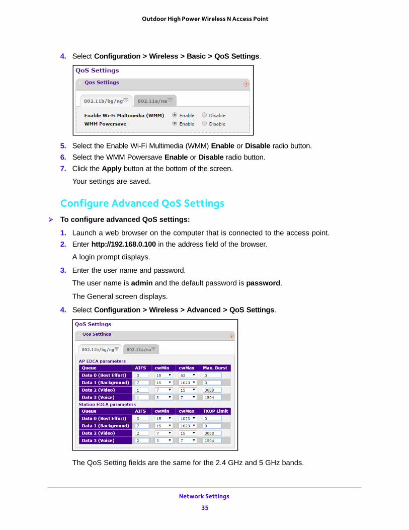
4. Select Configuration > Wireless > Basic > QoS Settings.
5. Select the Enable Wi-Fi Multimedia (WMM) Enable or Disable radio button.
6. Select the WMM Powersave Enable or Disable radio button.
7. Click the Apply button at the bottom of the screen.
Your settings are saved.
Configure Advanced QoS Settings To configure advanced QoS settings:
1. Launch a web browser on the computer that is connected to the access point.
2. Enter http://192.168.0.100 in the address field of the browser.
A login prompt displays.
3. Enter the user name and password.
The user name is admin and the default password is password.
The General screen displays.
4. Select Configuration > Wireless > Advanced > QoS Settings.
The QoS Setting fields are the same for the 2.4 GHz and 5 GHz bands.
Network Settings
35
Outdoor High Power Wireless N Access Point
5. (Optional) Change the default settings in the AP EDCA parameters section.
These parameters affect traffic flowing from the access point to the client station:
• AIFS. The Arbitration Inter-Frame Spacing (AIFS) interval specifies, in milliseconds, the wait time between data frames. Higher AIFS values mean higher priority to that queue. Valid values for AIFS are 1 through 255.
• CwMin. The minimum contention window (CwMin) value specifies the upper limit (in milliseconds) of a range from which the initial random back-off wait time is determined. Decreasing this value increases the priority of the queue. The value for CwMin must be lower than the value for CwMax. Valid values are 1, 3, 7, 15, 31, 63, 127, 255, 511, and 1024.
• CwMax. The maximum contention window (CwMax) value specifies (in milliseconds) the upper limit for the doubling of the random back-off value. Decreasing this value increases the priority of the queue. The value for CwMax must be higher than the value for CwMin. Valid values are 1, 3, 7, 15, 31, 63, 127, 255, 511, and 1024.
• Max. Burst. The maximum burst value specifies (in milliseconds) the maximum burst length allowed for packet bursts on the wireless network. A packet burst is a collection of multiple frames transmitted without header information. Decreasing this value increases the priority of the queue. Valid values for maximum burst length are 0.0 through 999.9.
6. (Optional) Change the default settings in the Station EDCA parameters section.
These parameters affect traffic flowing from the client station to the access point:
• AIFS. The Arbitration Inter-Frame Spacing (AIFS) interval specifies, in milliseconds, the wait time between data frames. Higher AIFS values means higher priority to that queue. Valid values for AIFS are 1 through 255.
• CwMin. The minimum contention window (CwMin) value specifies the upper limit (in milliseconds) of a range from which the initial random back-off wait time is determined. Decreasing this value increases the priority of the queue. The value for CwMin must be lower than the value for CwMax. Valid values are 1, 3, 7, 15, 31, 63, 127, 255, 511, and 1024.
• CwMax. The maximum contention window (CwMax) value specifies (in milliseconds) the upper limit for the doubling of the random back-off value. Decreasing this value increases the priority of the queue. The value for CwMax must be higher than the value for CwMin. Valid values are 1, 3, 7, 15, 31, 63, 127, 255, 511, and 1024.
• TXOP Limit. The transmission opportunity (TXOP) is an interval of time (in milliseconds) when a client station can initiate transmissions on the wireless medium (WM). Decreasing this value increases the priority of the queue. Valid values for maximum burst length are 0.0 through 999.9.
7. Click the Apply button at the bottom of the screen.
Your settings are saved.
Network Settings
36
Outdoor High Power Wireless N Access Point
Wireless Bridging and Repeating
You can use the access point as a component to build large bridged wireless networks. The following modes are available:
• Wireless point-to-point bridge mode. The access point communicates with one bridge-mode wireless station. You can associate wireless clients with this access point. For more information, see Set Up a Wireless Point-to-Point Bridge on page 37.
• Wireless point-to-multi-point bridge mode. The access point is the base station for a group of bridge-mode wireless stations. You can associate wireless clients with this access point.
The other bridge-mode wireless stations in the network must be set to point-to-point bridge mode and must use the MAC address of the base station. They send all traffic to the base station rather than communicating directly with each other. For more information, see Set Up a Wireless Point-to-Multi-Point Bridge on page 39.
Set Up a Wireless Point-to-Point BridgeCoordinate the following information ahead of time for each access point:
• MAC addresses. You must know the MAC address of each access point in the bridge network. You can use the 2.4 GHz or 5 GHz band for the wireless bridge, but the 2.4 GHz and 5 GHz bands of each access point use a unique MAC address.
• Authentication settings. You must specify the same wireless authentication settings for each access point in the bridge network. Each access point must use the same ESSID, channel, authentication mode, if any, and security settings.
• LAN address range. Each access point must be configured to operate in the same LAN network address range as the LAN devices.
• DHCP. If you are using DHCP, all access points must be set to obtain an IP address automatically. See Configure the Basic IP Settings on page 13.
When the wireless bridge is completed, a computer on either LAN segment can connect to the Internet and share files and printers with any other computers or servers connected to LAN Segment 1 or LAN Segment 2.
To configure a point-to-point wireless bridge between two access points:
1. Launch a web browser on the computer that is connected to the first access point.
2. In the address field of the browser, enter http://192.168.0.100.
A login prompt displays.
3. Enter the user name and password.
The user name is admin and the default password is password.
The General screen displays.
Network Settings
37
Outdoor High Power Wireless N Access Point
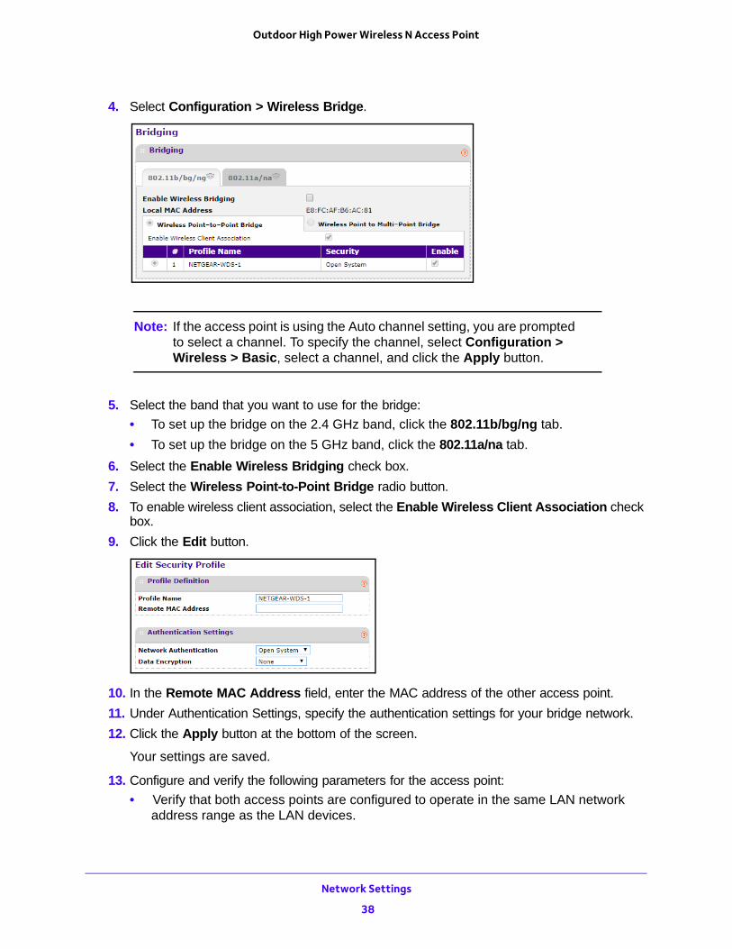
4. Select Configuration > Wireless Bridge.
Note: If the access point is using the Auto channel setting, you are prompted to select a channel. To specify the channel, select Configuration > Wireless > Basic, select a channel, and click the Apply button.
5. Select the band that you want to use for the bridge:
• To set up the bridge on the 2.4 GHz band, click the 802.11b/bg/ng tab.
• To set up the bridge on the 5 GHz band, click the 802.11a/na tab.
6. Select the Enable Wireless Bridging check box.
7. Select the Wireless Point-to-Point Bridge radio button.
8. To enable wireless client association, select the Enable Wireless Client Association check box.
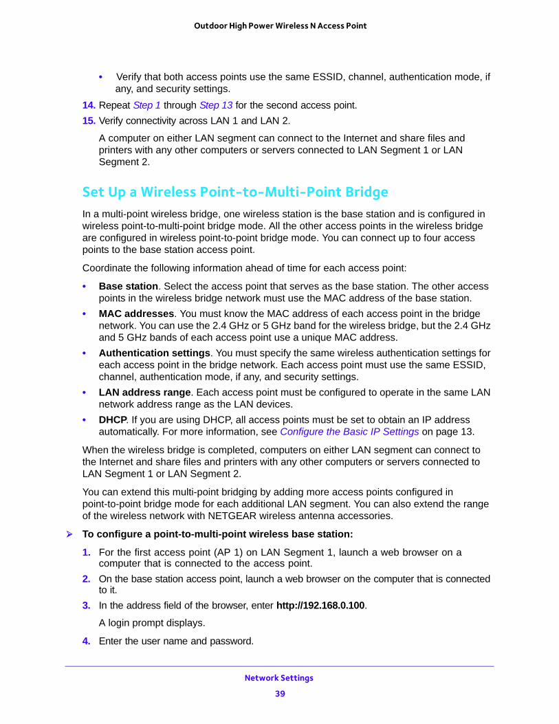
9. Click the Edit button.
10. In the Remote MAC Address field, enter the MAC address of the other access point.
11. Under Authentication Settings, specify the authentication settings for your bridge network.
12. Click the Apply button at the bottom of the screen.
Your settings are saved.
13. Configure and verify the following parameters for the access point:
• Verify that both access points are configured to operate in the same LAN network address range as the LAN devices.
Network Settings
38
Outdoor High Power Wireless N Access Point
• Verify that both access points use the same ESSID, channel, authentication mode, if any, and security settings.
14. Repeat Step 1 through Step 13 for the second access point.
15. Verify connectivity across LAN 1 and LAN 2.
A computer on either LAN segment can connect to the Internet and share files and printers with any other computers or servers connected to LAN Segment 1 or LAN Segment 2.
Set Up a Wireless Point-to-Multi-Point BridgeIn a multi-point wireless bridge, one wireless station is the base station and is configured in wireless point-to-multi-point bridge mode. All the other access points in the wireless bridge are configured in wireless point-to-point bridge mode. You can connect up to four access points to the base station access point.
Coordinate the following information ahead of time for each access point:
• Base station. Select the access point that serves as the base station. The other access points in the wireless bridge network must use the MAC address of the base station.
• MAC addresses. You must know the MAC address of each access point in the bridge network. You can use the 2.4 GHz or 5 GHz band for the wireless bridge, but the 2.4 GHz and 5 GHz bands of each access point use a unique MAC address.
• Authentication settings. You must specify the same wireless authentication settings for each access point in the bridge network. Each access point must use the same ESSID, channel, authentication mode, if any, and security settings.
• LAN address range. Each access point must be configured to operate in the same LAN network address range as the LAN devices.
• DHCP. If you are using DHCP, all access points must be set to obtain an IP address automatically. For more information, see Configure the Basic IP Settings on page 13.
When the wireless bridge is completed, computers on either LAN segment can connect to the Internet and share files and printers with any other computers or servers connected to LAN Segment 1 or LAN Segment 2.
You can extend this multi-point bridging by adding more access points configured in point-to-point bridge mode for each additional LAN segment. You can also extend the range of the wireless network with NETGEAR wireless antenna accessories.
To configure a point-to-multi-point wireless base station:
1. For the first access point (AP 1) on LAN Segment 1, launch a web browser on a computer that is connected to the access point.
2. On the base station access point, launch a web browser on the computer that is connected to it.
3. In the address field of the browser, enter http://192.168.0.100.
A login prompt displays.
4. Enter the user name and password.
Network Settings
39
Outdoor High Power Wireless N Access Point
The user name is admin and the default password is password.
The General screen displays.
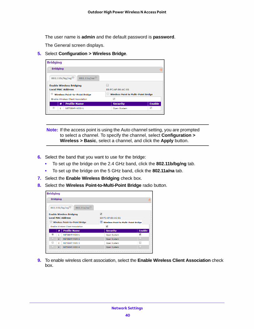
5. Select Configuration > Wireless Bridge.
Note: If the access point is using the Auto channel setting, you are prompted to select a channel. To specify the channel, select Configuration > Wireless > Basic, select a channel, and click the Apply button.
6. Select the band that you want to use for the bridge:
• To set up the bridge on the 2.4 GHz band, click the 802.11b/bg/ng tab.
• To set up the bridge on the 5 GHz band, click the 802.11a/na tab.
7. Select the Enable Wireless Bridging check box.
8. Select the Wireless Point-to-Multi-Point Bridge radio button.
9. To enable wireless client association, select the Enable Wireless Client Association check box.
Network Settings
40
Outdoor High Power Wireless N Access Point
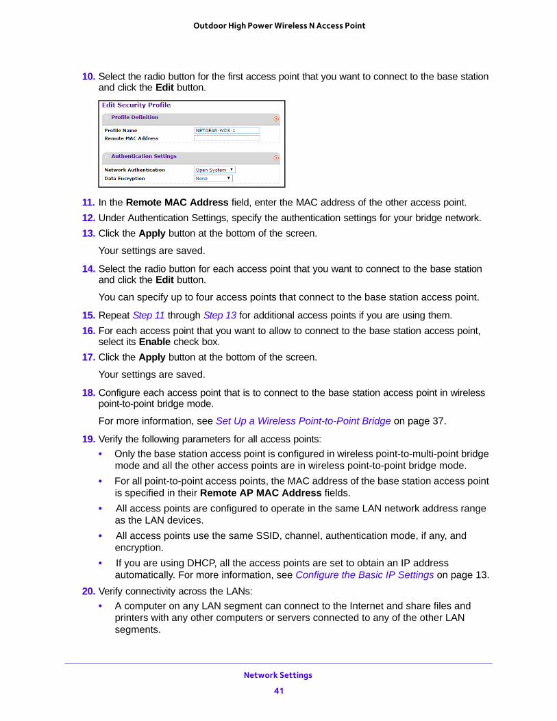
10. Select the radio button for the first access point that you want to connect to the base station and click the Edit button.
11. In the Remote MAC Address field, enter the MAC address of the other access point.
12. Under Authentication Settings, specify the authentication settings for your bridge network.
13. Click the Apply button at the bottom of the screen.
Your settings are saved.
14. Select the radio button for each access point that you want to connect to the base station and click the Edit button.
You can specify up to four access points that connect to the base station access point.
15. Repeat Step 11 through Step 13 for additional access points if you are using them.
16. For each access point that you want to allow to connect to the base station access point, select its Enable check box.
17. Click the Apply button at the bottom of the screen.
Your settings are saved.
18. Configure each access point that is to connect to the base station access point in wireless point-to-point bridge mode.
For more information, see Set Up a Wireless Point-to-Point Bridge on page 37.
19. Verify the following parameters for all access points:
• Only the base station access point is configured in wireless point-to-multi-point bridge mode and all the other access points are in wireless point-to-point bridge mode.
• For all point-to-point access points, the MAC address of the base station access point is specified in their Remote AP MAC Address fields.
• All access points are configured to operate in the same LAN network address range as the LAN devices.
• All access points use the same SSID, channel, authentication mode, if any, and encryption.
• If you are using DHCP, all the access points are set to obtain an IP address automatically. For more information, see Configure the Basic IP Settings on page 13.
20. Verify connectivity across the LANs:
• A computer on any LAN segment can connect to the Internet and share files and printers with any other computers or servers connected to any of the other LAN segments.
Network Settings
41
Outdoor High Power Wireless N Access Point
• The wireless stations that you enable can connect to the access points. If you require wireless stations to access any LAN segment, you can add additional access points configured in wireless bridge mode to any LAN segment.
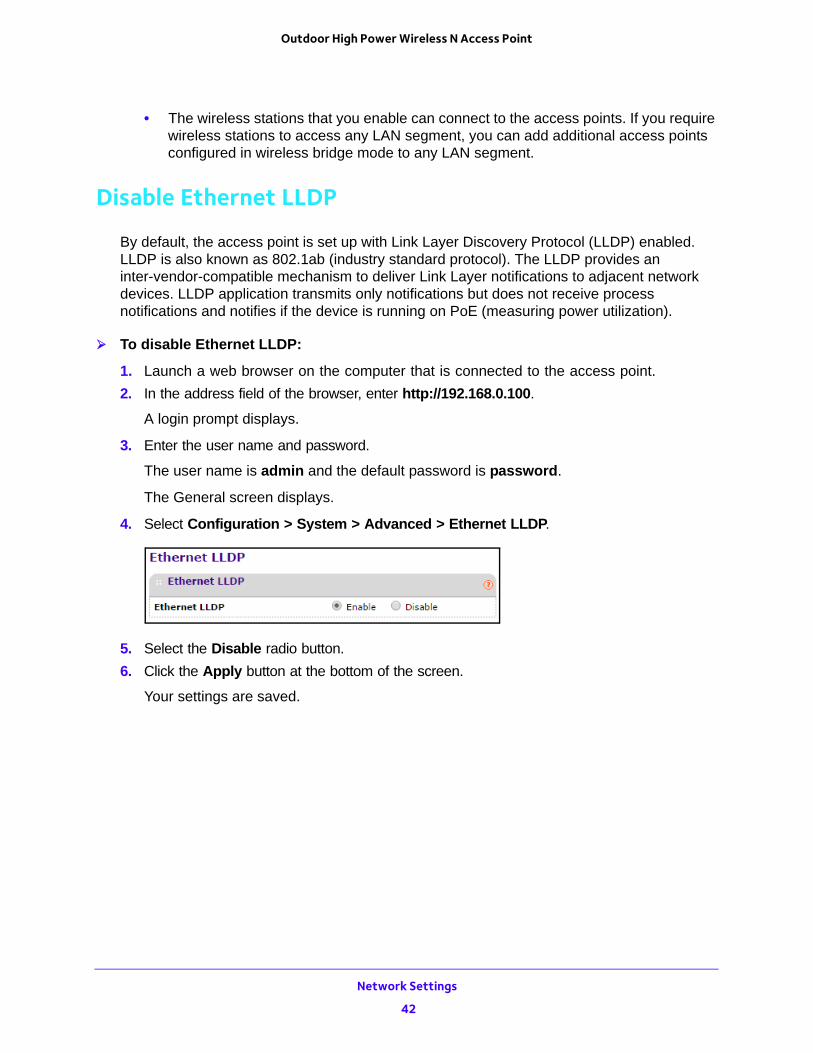
Disable Ethernet LLDP
By default, the access point is set up with Link Layer Discovery Protocol (LLDP) enabled. LLDP is also known as 802.1ab (industry standard protocol). The LLDP provides an inter-vendor-compatible mechanism to deliver Link Layer notifications to adjacent network devices. LLDP application transmits only notifications but does not receive process notifications and notifies if the device is running on PoE (measuring power utilization).
To disable Ethernet LLDP:
1. Launch a web browser on the computer that is connected to the access point.
2. In the address field of the browser, enter http://192.168.0.100.
A login prompt displays.
3. Enter the user name and password.
The user name is admin and the default password is password.
The General screen displays.
4. Select Configuration > System > Advanced > Ethernet LLDP.
5. Select the Disable radio button.
6. Click the Apply button at the bottom of the screen.
Your settings are saved.
Network Settings
42
4
4. Manage the Access PointThis chapter covers the following topics:
• Change the admin Password
• Reboot the Access Point
• Set Up a Remote Console
• Set Up SNMP
• Upgrade the Firmware
• Manage the Configuration File
• Enable a Syslog Server
43
Outdoor High Power Wireless N Access Point
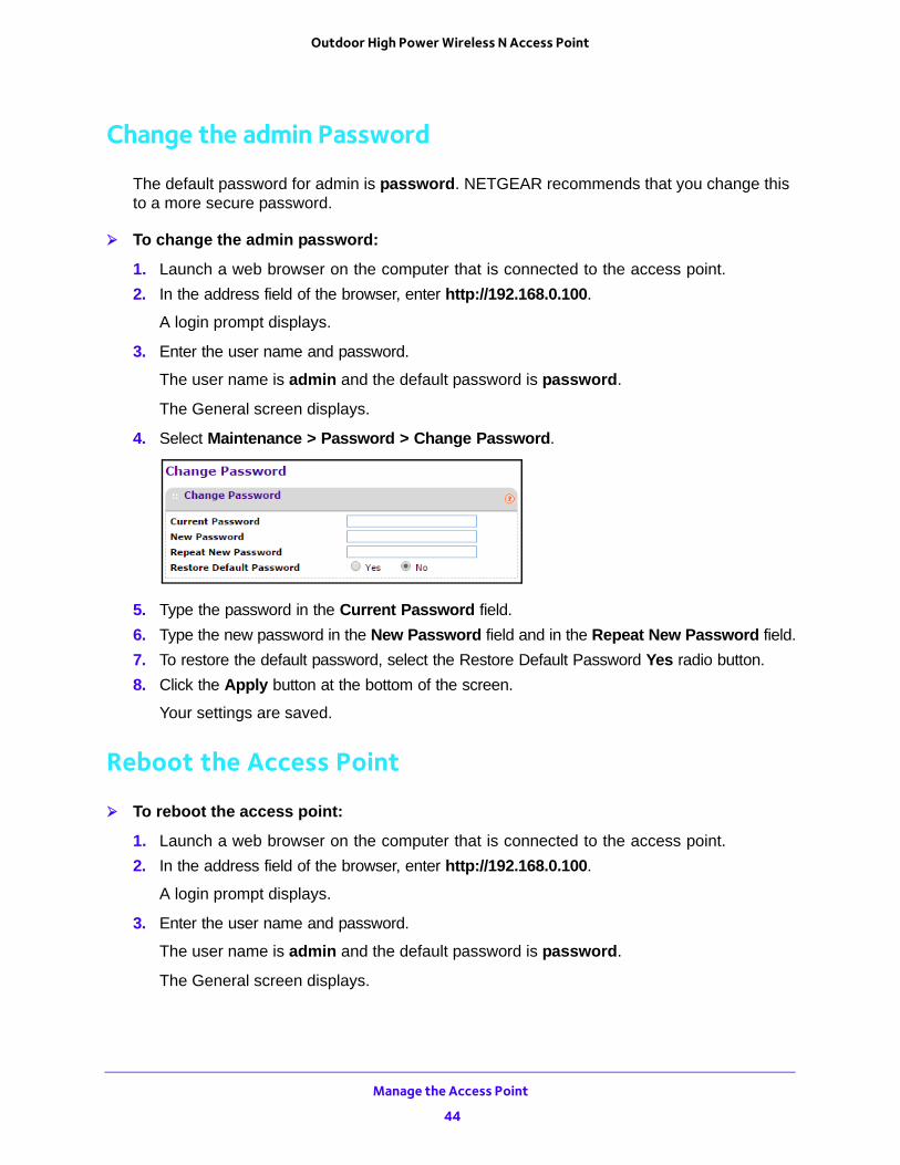
Change the admin Password
The default password for admin is password. NETGEAR recommends that you change this to a more secure password.
To change the admin password:
1. Launch a web browser on the computer that is connected to the access point.
2. In the address field of the browser, enter http://192.168.0.100.
A login prompt displays.
3. Enter the user name and password.
The user name is admin and the default password is password.
The General screen displays.
4. Select Maintenance > Password > Change Password.
5. Type the password in the Current Password field.
6. Type the new password in the New Password field and in the Repeat New Password field.
7. To restore the default password, select the Restore Default Password Yes radio button.
8. Click the Apply button at the bottom of the screen.
Your settings are saved.
Reboot the Access Point
To reboot the access point:
1. Launch a web browser on the computer that is connected to the access point.
2. In the address field of the browser, enter http://192.168.0.100.
A login prompt displays.
3. Enter the user name and password.
The user name is admin and the default password is password.
The General screen displays.
Manage the Access Point
44
Outdoor High Power Wireless N Access Point
4. Select Maintenance > Reset.
5. Select the Yes radio button.
6. Click the Apply button at the bottom of the screen.
The access point reboots.
Set Up a Remote Console
To set up remote console:
1. Launch a web browser on the computer that is connected to the access point.
2. In the address field of the browser, enter http://192.168.0.100.
A login prompt displays.
3. Enter the user name and password.
The user name is admin and the default password is password.
The General screen displays.
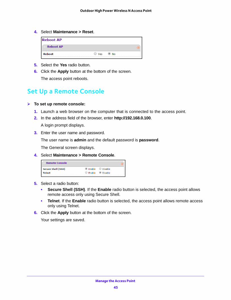
4. Select Maintenance > Remote Console.
5. Select a radio button:
• Secure Shell (SSH). If the Enable radio button is selected, the access point allows remote access only using Secure Shell.
• Telnet. If the Enable radio button is selected, the access point allows remote access only using Telnet.
6. Click the Apply button at the bottom of the screen.
Your settings are saved.
Manage the Access Point
45
Outdoor High Power Wireless N Access Point
Set Up SNMP
Enable SNMP to allow the SNMP network management software, such as HP OpenView, to manage the wireless access point by using the SNMPv1/v2 protocol.
To set up SNMP:
1. Launch a web browser on the computer that is connected to the access point.
2. In the address field of the browser, enter http://192.168.0.100.
A login prompt displays.
3. Enter the user name and password.
The user name is admin and the default password is password.
The General screen displays.
4. Select Maintenance > SNMP.
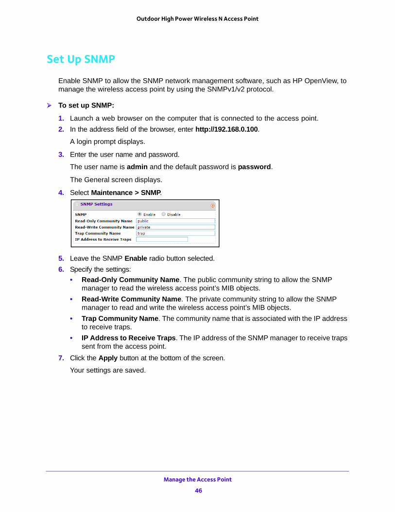
5. Leave the SNMP Enable radio button selected.
6. Specify the settings:
• Read-Only Community Name. The public community string to allow the SNMP manager to read the wireless access point’s MIB objects.
• Read-Write Community Name. The private community string to allow the SNMP manager to read and write the wireless access point’s MIB objects.
• Trap Community Name. The community name that is associated with the IP address to receive traps.
• IP Address to Receive Traps. The IP address of the SNMP manager to receive traps sent from the access point.
7. Click the Apply button at the bottom of the screen.
Your settings are saved.
Manage the Access Point
46
Outdoor High Power Wireless N Access Point
Upgrade the Firmware
The firmware is stored in flash memory and can be updated as NETGEAR releases new firmware. You can download upgrade files from the NETGEAR website. If the upgrade file is compressed (.zip file), you must first extract the image file before sending it to the access point. You can send the upgrade file using your browser.
Note: The web browser must support HTTP uploads.
You cannot perform the software upgrade from a computer that is connected to the access point wirelessly. You must use a computer that is connected with an Ethernet cable.
WARNING:
When uploading firmware to the access point, do not interrupt the web browser by closing the window, clicking a link, or loading a new page. If the browser is interrupted, the upload might fail, corrupt the software, and render the access point inoperable.
To upgrade the firmware:
1. Download the new software file from the NETGEAR website, save it to your hard disk, and unzip it.
2. Launch a web browser on the computer that is connected to the access point.
3. In the address field of the browser, enter http://192.168.0.100.
A login prompt displays.
4. Enter the user name and password.
The user name is admin and the default password is password.
The General screen displays.
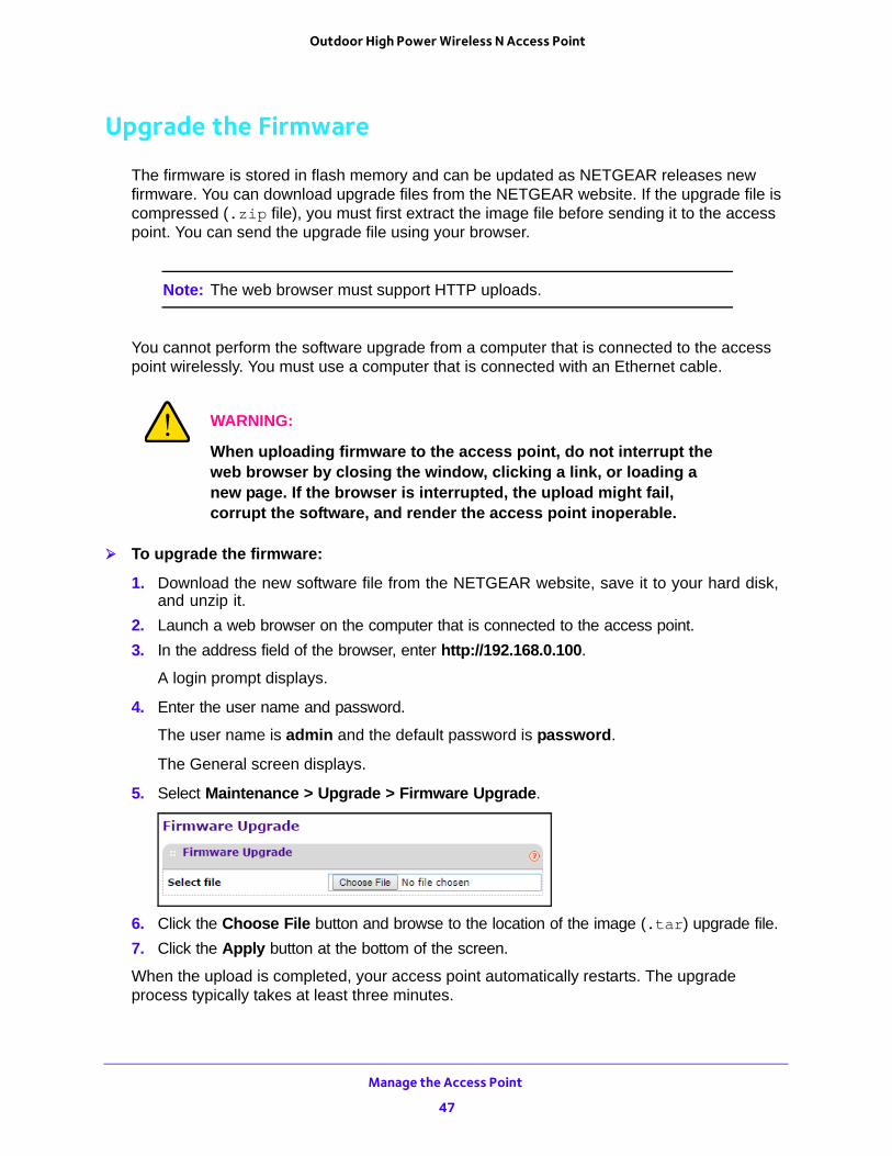
5. Select Maintenance > Upgrade > Firmware Upgrade.
6. Click the Choose File button and browse to the location of the image (.tar) upgrade file.
7. Click the Apply button at the bottom of the screen.
When the upload is completed, your access point automatically restarts. The upgrade process typically takes at least three minutes.
Manage the Access Point
47
Outdoor High Power Wireless N Access Point
Manage the Configuration File
The access point settings are stored in the access point in a configuration file. This file can be saved (backed up) or restored.
Back Up the Configuration File To back up the access point settings in a configuration file:
1. Launch a web browser on the computer that is connected to the access point.
2. In the address field of the browser, enter http://192.168.0.100.
A login prompt displays.
3. Enter the user name and password.
The user name is admin and the default password is password.
The General screen displays.
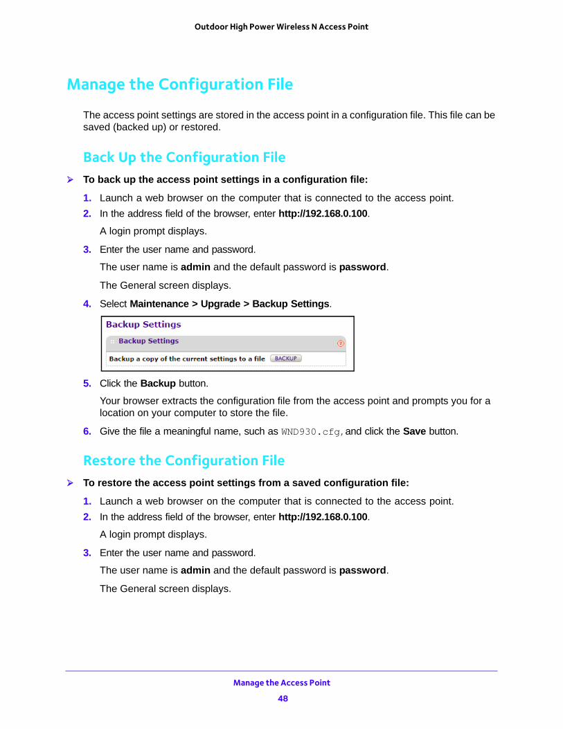
4. Select Maintenance > Upgrade > Backup Settings.
5. Click the Backup button.
Your browser extracts the configuration file from the access point and prompts you for a location on your computer to store the file.
6. Give the file a meaningful name, such as WND930.cfg,and click the Save button.
Restore the Configuration File To restore the access point settings from a saved configuration file:
1. Launch a web browser on the computer that is connected to the access point.
2. In the address field of the browser, enter http://192.168.0.100.
A login prompt displays.
3. Enter the user name and password.
The user name is admin and the default password is password.
The General screen displays.
Manage the Access Point
48
Outdoor High Power Wireless N Access Point
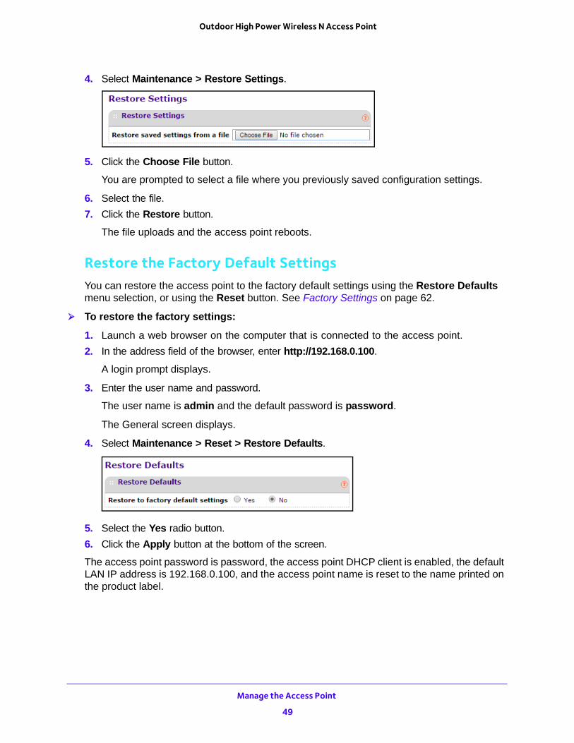
4. Select Maintenance > Restore Settings.
5. Click the Choose File button.
You are prompted to select a file where you previously saved configuration settings.
6. Select the file.
7. Click the Restore button.
The file uploads and the access point reboots.
Restore the Factory Default SettingsYou can restore the access point to the factory default settings using the Restore Defaults menu selection, or using the Reset button. See Factory Settings on page 62.
To restore the factory settings:
1. Launch a web browser on the computer that is connected to the access point.
2. In the address field of the browser, enter http://192.168.0.100.
A login prompt displays.
3. Enter the user name and password.
The user name is admin and the default password is password.
The General screen displays.
4. Select Maintenance > Reset > Restore Defaults.
5. Select the Yes radio button.
6. Click the Apply button at the bottom of the screen.
The access point password is password, the access point DHCP client is enabled, the default LAN IP address is 192.168.0.100, and the access point name is reset to the name printed on the product label.
Manage the Access Point
49
Outdoor High Power Wireless N Access Point
Enable a Syslog Server
You can enable the syslog option if your LAN includes a syslog server.
To enable a syslog server:
1. Launch a web browser on the computer that is connected to the access point.
2. In the address field of the browser, enter http://192.168.0.100.
A login prompt displays.
3. Enter the user name and password.
The user name is admin and the default password is password.
The General screen displays.
4. Select Configuration > System > Advanced > Syslog.
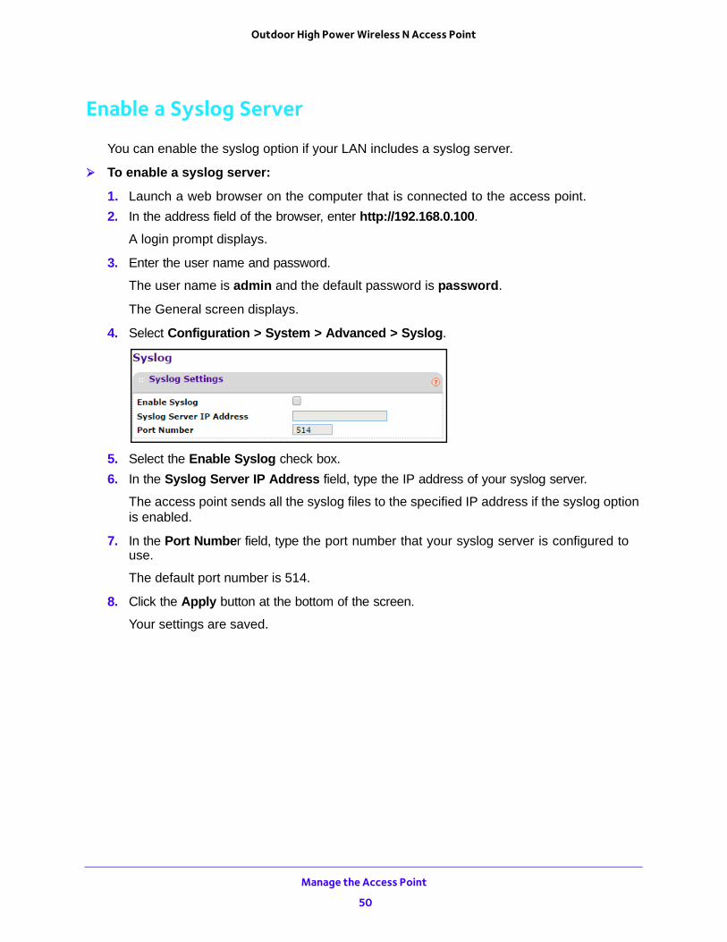
5. Select the Enable Syslog check box.
6. In the Syslog Server IP Address field, type the IP address of your syslog server.
The access point sends all the syslog files to the specified IP address if the syslog option is enabled.
7. In the Port Number field, type the port number that your syslog server is configured to use.
The default port number is 514.
8. Click the Apply button at the bottom of the screen.
Your settings are saved.
Manage the Access Point
50
5
5. MonitoringThis chapter covers the following topics:
• View System Information
• View Wireless Stations
• View the Activity Log
• View Network Traffic Statistics
• Enable Wireless Packet Capture
51
Outdoor High Power Wireless N Access Point
View System Information
You can view a summary of the current access point configuration settings, including current IP settings and current wireless settings. This information is read-only, so any changes must be made on other screens.
To view system information:
1. Launch a web browser on the computer that is connected to the access point.
2. In the address field of the browser, enter http://192.168.0.100.
A login prompt displays.
3. Enter the user name and password.
The user name is admin and the default password is password.
The General screen displays.
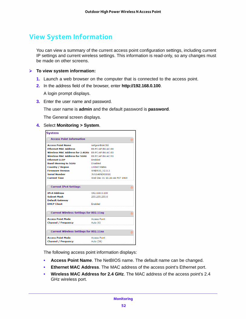
4. Select Monitoring > System.
The following access point information displays:
• Access Point Name. The NetBIOS name. The default name can be changed.
• Ethernet MAC Address. The MAC address of the access point’s Ethernet port.
• Wireless MAC Address for 2.4 GHz. The MAC address of the access point’s 2.4 GHz wireless port.
Monitoring
52
Outdoor High Power Wireless N Access Point
• Wireless MAC Address for 5 GHz. The MAC address of the access point’s 5 GHz wireless port.
• Band Steering. Indicates whether band steering is enabled or disabled.
• Country/Region. The domain or region for which the access point is licensed for use. It might not be legal to operate this access point in a region other than the one identified in this field.
• Firmware Version. The version of the firmware currently installed.
• Serial Number. The serial number of the device.
• Current Time. The time setting for the access point.
The following current IPv4 settings information displays:
• IP Address. The IP address of the access point.
• Subnet Mask. The subnet mask for the access point.
• Default Gateway. The default gateway for the access point communication.
• DHCP Client. Enabled indicates that the current IP address was obtained from a DHCP server on your network. Disabled indicates a static IP configuration.
The following current wireless settings for each wireless band display:
• Operating Mode. Identifies the 802.11 operating mode of the access point. The operating mode is one of the following:
- Access Point
- Point-to-Point Bridge
- Point-to-Point Bridge with Access Point
- Multi-Point Bridge
• Channel / Frequency. Identifies the channel that the wireless port is using.
View Wireless Stations
You can view all IP devices associated with this access point in the wireless network defined by the wireless network name (SSID). If your network includes more than one access point sharing the same SSID, remember that you can view only the wireless stations associated with this access point.
To view the Available Wireless Stations list:
1. Launch a web browser on the computer that is connected to the access point.
2. In the address field of the browser, enter http://192.168.0.100.
A login prompt displays.
3. Enter the user name and password.
The user name is admin and the default password is password.
The General screen displays.
Monitoring
53
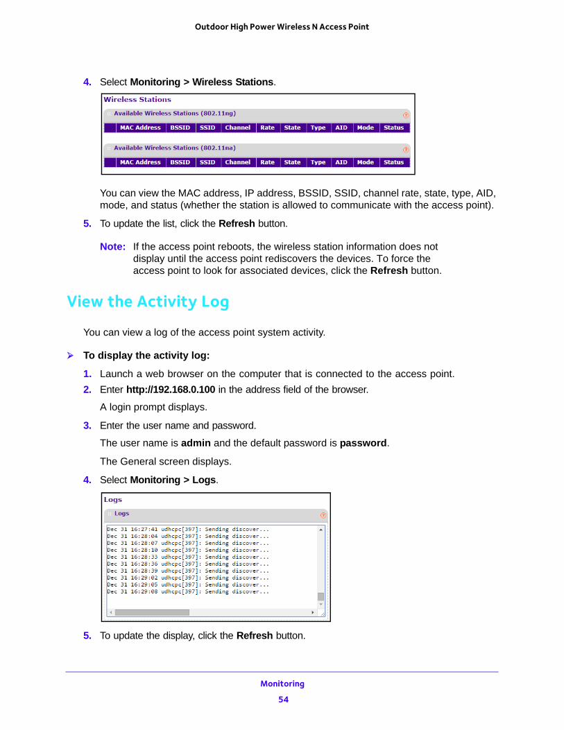
Outdoor High Power Wireless N Access Point
4. Select Monitoring > Wireless Stations.
You can view the MAC address, IP address, BSSID, SSID, channel rate, state, type, AID, mode, and status (whether the station is allowed to communicate with the access point).
5. To update the list, click the Refresh button.
Note: If the access point reboots, the wireless station information does not display until the access point rediscovers the devices. To force the access point to look for associated devices, click the Refresh button.
View the Activity Log
You can view a log of the access point system activity.
To display the activity log:
1. Launch a web browser on the computer that is connected to the access point.
2. Enter http://192.168.0.100 in the address field of the browser.
A login prompt displays.
3. Enter the user name and password.
The user name is admin and the default password is password.
The General screen displays.
4. Select Monitoring > Logs.
5. To update the display, click the Refresh button.
Monitoring
54
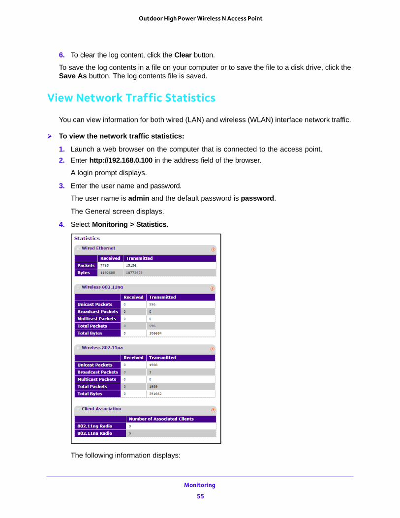
Outdoor High Power Wireless N Access Point
6. To clear the log content, click the Clear button.
To save the log contents in a file on your computer or to save the file to a disk drive, click the Save As button. The log contents file is saved.
View Network Traffic Statistics
You can view information for both wired (LAN) and wireless (WLAN) interface network traffic.
To view the network traffic statistics:
1. Launch a web browser on the computer that is connected to the access point.
2. Enter http://192.168.0.100 in the address field of the browser.
A login prompt displays.
3. Enter the user name and password.
The user name is admin and the default password is password.
The General screen displays.
4. Select Monitoring > Statistics.
The following information displays:
Monitoring
55
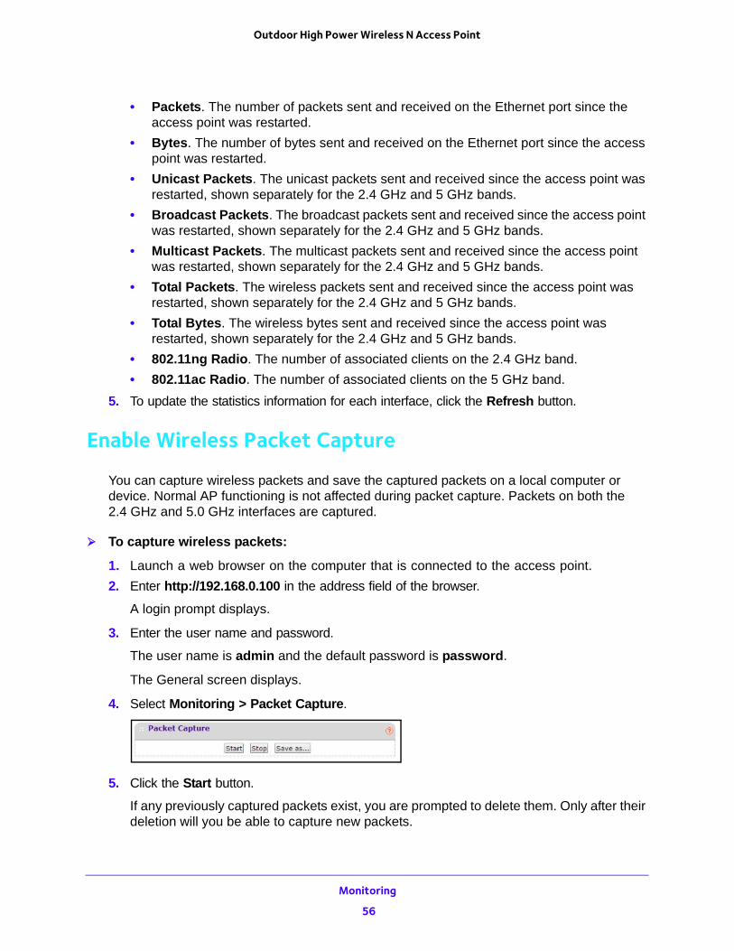
Outdoor High Power Wireless N Access Point
• Packets. The number of packets sent and received on the Ethernet port since the access point was restarted.
• Bytes. The number of bytes sent and received on the Ethernet port since the access point was restarted.
• Unicast Packets. The unicast packets sent and received since the access point was restarted, shown separately for the 2.4 GHz and 5 GHz bands.
• Broadcast Packets. The broadcast packets sent and received since the access point was restarted, shown separately for the 2.4 GHz and 5 GHz bands.
• Multicast Packets. The multicast packets sent and received since the access point was restarted, shown separately for the 2.4 GHz and 5 GHz bands.
• Total Packets. The wireless packets sent and received since the access point was restarted, shown separately for the 2.4 GHz and 5 GHz bands.
• Total Bytes. The wireless bytes sent and received since the access point was restarted, shown separately for the 2.4 GHz and 5 GHz bands.
• 802.11ng Radio. The number of associated clients on the 2.4 GHz band.
• 802.11ac Radio. The number of associated clients on the 5 GHz band.
5. To update the statistics information for each interface, click the Refresh button.
Enable Wireless Packet Capture
You can capture wireless packets and save the captured packets on a local computer or device. Normal AP functioning is not affected during packet capture. Packets on both the 2.4 GHz and 5.0 GHz interfaces are captured.
To capture wireless packets:
1. Launch a web browser on the computer that is connected to the access point.
2. Enter http://192.168.0.100 in the address field of the browser.
A login prompt displays.
3. Enter the user name and password.
The user name is admin and the default password is password.
The General screen displays.
4. Select Monitoring > Packet Capture.
5. Click the Start button.
If any previously captured packets exist, you are prompted to delete them. Only after their deletion will you be able to capture new packets.
Monitoring
56

Outdoor High Power Wireless N Access Point
The access point captures wireless packets coming from or going to the access point on the current operating channel.
6. To stop the current packet capture, click the Stop button.
7. To save the captured packets to a file on the computer or device that you are using, click the Save as button.
Monitoring
57
6
6. Troubleshooting and DebuggingThis chapter covers the following topics:
• Troubleshooting with the LEDs
• Cannot Connect to the Access Point to Configure It
• Wireless Access to the Network
• Time-Out Error for a URL or IP Address
Note: For up-to-date WND930 installation details and troubleshooting guidance, visit http://support.netgear.com.
58
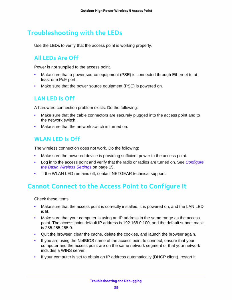
Outdoor High Power Wireless N Access Point
Troubleshooting with the LEDs
Use the LEDs to verify that the access point is working properly.
All LEDs Are OffPower is not supplied to the access point.
• Make sure that a power source equipment (PSE) is connected through Ethernet to at least one PoE port.
• Make sure that the power source equipment (PSE) is powered on.
LAN LED Is OffA hardware connection problem exists. Do the following:
• Make sure that the cable connectors are securely plugged into the access point and to the network switch.
• Make sure that the network switch is turned on.
WLAN LED Is OffThe wireless connection does not work. Do the following:
• Make sure the powered device is providing sufficient power to the access point.
• Log in to the access point and verify that the radio or radios are turned on. See Configure the Basic Wireless Settings on page 15.
• If the WLAN LED remains off, contact NETGEAR technical support.
Cannot Connect to the Access Point to Configure It
Check these items:
• Make sure that the access point is correctly installed, it is powered on, and the LAN LED is lit.
• Make sure that your computer is using an IP address in the same range as the access point. The access point default IP address is 192.168.0.100, and the default subnet mask is 255.255.255.0.
• Quit the browser, clear the cache, delete the cookies, and launch the browser again.
• If you are using the NetBIOS name of the access point to connect, ensure that your computer and the access point are on the same network segment or that your network includes a WINS server.
• If your computer is set to obtain an IP address automatically (DHCP client), restart it.
Troubleshooting and Debugging
59
Outdoor High Power Wireless N Access Point
Wireless Access to the Network
If you cannot connect wirelessly, the wireless radio might be turned off (see Configure the Basic Wireless Settings on page 15) or a configuration problem might exist. For a configuration problem, check these items:
• Make sure that the SSID and wireless security settings of the wireless device are the same as those of the access point.
• The wireless device might not be configured with the correct TCP/IP settings to communicate with the network. Restart the wireless device and check that TCP/IP is set up correctly for that network.
• The access point default values might not work with your network. Check the access point default configuration against the configuration of other devices in your network. For information about changing the default values.
Time-Out Error for a URL or IP Address
A number of things could be causing this. Try the following troubleshooting steps:
• Check whether other computers on the network work without errors. If they do, ensure that your computer’s TCP/IP settings are correct. If you are using a fixed (static) IP address, check the subnet mask, default gateway, DNS, and IP addresses.
• If the computers are configured correctly but still not working, ensure that the access point is connected and turned on. Connect to it and check its settings. If you cannot connect to it, check the LAN and power connections.
• If the access point is configured correctly, check your Internet connection (DSL or cable modem, and so on) to make sure that it is working correctly.
• Try again.
Troubleshooting and Debugging
60

A
A. Supplemental InformationThis appendix covers the following topics:
• Factory Settings
• Technical Specifications
61
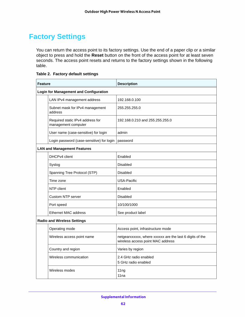
Outdoor High Power Wireless N Access Point
Factory Settings
You can return the access point to its factory settings. Use the end of a paper clip or a similar object to press and hold the Reset button on the front of the access point for at least seven seconds. The access point resets and returns to the factory settings shown in the following table.
Table 2. Factory default settings
Feature Description
Login for Management and Configuration
LAN IPv4 management address 192.168.0.100
Subnet mask for IPv4 management address
255.255.255.0
Required static IPv4 address for management computer
192.168.0.210 and 255.255.255.0
User name (case-sensitive) for login admin
Login password (case-sensitive) for login password
LAN and Management Features
DHCPv4 client Enabled
Syslog Disabled
Spanning Tree Protocol (STP) Disabled
Time zone USA-Pacific
NTP client Enabled
Custom NTP server Disabled
Port speed 10/100/1000
Ethernet MAC address See product label
Radio and Wireless Settings
Operating mode Access point, infrastructure mode
Wireless access point name netgearxxxxxx, where xxxxxx are the last 6 digits of the wireless access point MAC address
Country and region Varies by region
Wireless communication 2.4 GHz radio enabled
5 GHz radio enabled
Wireless modes 11ng
11na
Supplemental Information
62
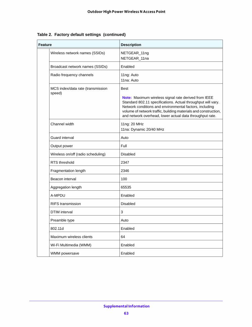
Outdoor High Power Wireless N Access Point
Wireless network names (SSIDs) NETGEAR_11ng
NETGEAR_11na
Broadcast network names (SSIDs) Enabled
Radio frequency channels 11ng: Auto
11na: Auto
MCS index/data rate (transmission speed)
Best
Note: Maximum wireless signal rate derived from IEEE Standard 802.11 specifications. Actual throughput will vary. Network conditions and environmental factors, including volume of network traffic, building materials and construction, and network overhead, lower actual data throughput rate.
Channel width 11ng: 20 MHz
11na: Dynamic 20/40 MHz
Guard interval Auto
Output power Full
Wireless on/off (radio scheduling) Disabled
RTS threshold 2347
Fragmentation length 2346
Beacon interval 100
Aggregation length 65535
A-MPDU Enabled
RIFS transmission Disabled
DTIM interval 3
Preamble type Auto
802.11d Enabled
Maximum wireless clients 64
Wi-Fi Multimedia (WMM) Enabled
WMM powersave Enabled
Table 2. Factory default settings (continued)
Feature Description
Supplemental Information
63
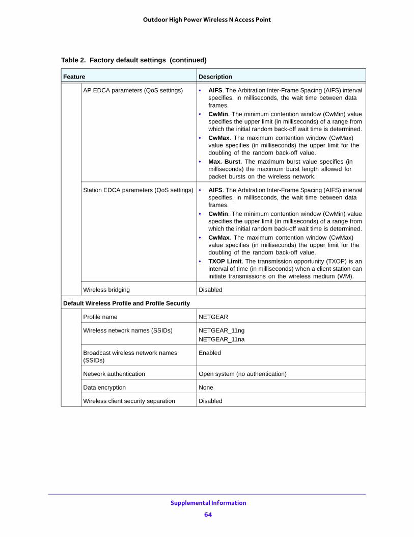
Outdoor High Power Wireless N Access Point
AP EDCA parameters (QoS settings) • AIFS. The Arbitration Inter-Frame Spacing (AIFS) interval specifies, in milliseconds, the wait time between data frames.
• CwMin. The minimum contention window (CwMin) value specifies the upper limit (in milliseconds) of a range from which the initial random back-off wait time is determined.
• CwMax. The maximum contention window (CwMax) value specifies (in milliseconds) the upper limit for the doubling of the random back-off value.
• Max. Burst. The maximum burst value specifies (in milliseconds) the maximum burst length allowed for packet bursts on the wireless network.
Station EDCA parameters (QoS settings) • AIFS. The Arbitration Inter-Frame Spacing (AIFS) interval specifies, in milliseconds, the wait time between data frames.
• CwMin. The minimum contention window (CwMin) value specifies the upper limit (in milliseconds) of a range from which the initial random back-off wait time is determined.
• CwMax. The maximum contention window (CwMax) value specifies (in milliseconds) the upper limit for the doubling of the random back-off value.
• TXOP Limit. The transmission opportunity (TXOP) is an interval of time (in milliseconds) when a client station can initiate transmissions on the wireless medium (WM).
Wireless bridging Disabled
Default Wireless Profile and Profile Security
Profile name NETGEAR
Wireless network names (SSIDs) NETGEAR_11ng
NETGEAR_11na
Broadcast wireless network names (SSIDs)
Enabled
Network authentication Open system (no authentication)
Data encryption None
Wireless client security separation Disabled
Table 2. Factory default settings (continued)
Feature Description
Supplemental Information
64
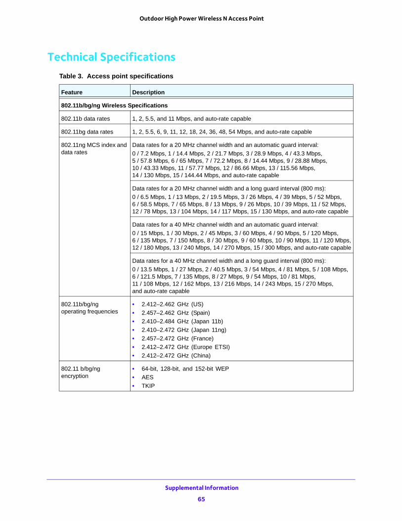
Outdoor High Power Wireless N Access Point
Technical SpecificationsTable 3. Access point specifications
Feature Description
802.11b/bg/ng Wireless Specifications
802.11b data rates 1, 2, 5.5, and 11 Mbps, and auto-rate capable
802.11bg data rates 1, 2, 5.5, 6, 9, 11, 12, 18, 24, 36, 48, 54 Mbps, and auto-rate capable
802.11ng MCS index and data rates
Data rates for a 20 MHz channel width and an automatic guard interval:
0 / 7.2 Mbps, 1 / 14.4 Mbps, 2 / 21.7 Mbps, 3 / 28.9 Mbps, 4 / 43.3 Mbps,5 / 57.8 Mbps, 6 / 65 Mbps, 7 / 72.2 Mbps, 8 / 14.44 Mbps, 9 / 28.88 Mbps,10 / 43.33 Mbps, 11 / 57.77 Mbps, 12 / 86.66 Mbps, 13 / 115.56 Mbps, 14 / 130 Mbps, 15 / 144.44 Mbps, and auto-rate capable
Data rates for a 20 MHz channel width and a long guard interval (800 ms):
0 / 6.5 Mbps, 1 / 13 Mbps, 2 / 19.5 Mbps, 3 / 26 Mbps, 4 / 39 Mbps, 5 / 52 Mbps,6 / 58.5 Mbps, 7 / 65 Mbps, 8 / 13 Mbps, 9 / 26 Mbps, 10 / 39 Mbps, 11 / 52 Mbps,12 / 78 Mbps, 13 / 104 Mbps, 14 / 117 Mbps, 15 / 130 Mbps, and auto-rate capable
Data rates for a 40 MHz channel width and an automatic guard interval:
0 / 15 Mbps, 1 / 30 Mbps, 2 / 45 Mbps, 3 / 60 Mbps, 4 / 90 Mbps, 5 / 120 Mbps,6 / 135 Mbps, 7 / 150 Mbps, 8 / 30 Mbps, 9 / 60 Mbps, 10 / 90 Mbps, 11 / 120 Mbps,12 / 180 Mbps, 13 / 240 Mbps, 14 / 270 Mbps, 15 / 300 Mbps, and auto-rate capable
Data rates for a 40 MHz channel width and a long guard interval (800 ms):
0 / 13.5 Mbps, 1 / 27 Mbps, 2 / 40.5 Mbps, 3 / 54 Mbps, 4 / 81 Mbps, 5 / 108 Mbps,6 / 121.5 Mbps, 7 / 135 Mbps, 8 / 27 Mbps, 9 / 54 Mbps, 10 / 81 Mbps,11 / 108 Mbps, 12 / 162 Mbps, 13 / 216 Mbps, 14 / 243 Mbps, 15 / 270 Mbps,and auto-rate capable
802.11b/bg/ngoperating frequencies
• 2.412–2.462 GHz (US)
• 2.457–2.462 GHz (Spain)
• 2.410–2.484 GHz (Japan 11b)
• 2.410–2.472 GHz (Japan 11ng)
• 2.457–2.472 GHz (France)
• 2.412–2.472 GHz (Europe ETSI)
• 2.412–2.472 GHz (China)
802.11 b/bg/ng encryption
• 64-bit, 128-bit, and 152-bit WEP
• AES
• TKIP
Supplemental Information
65
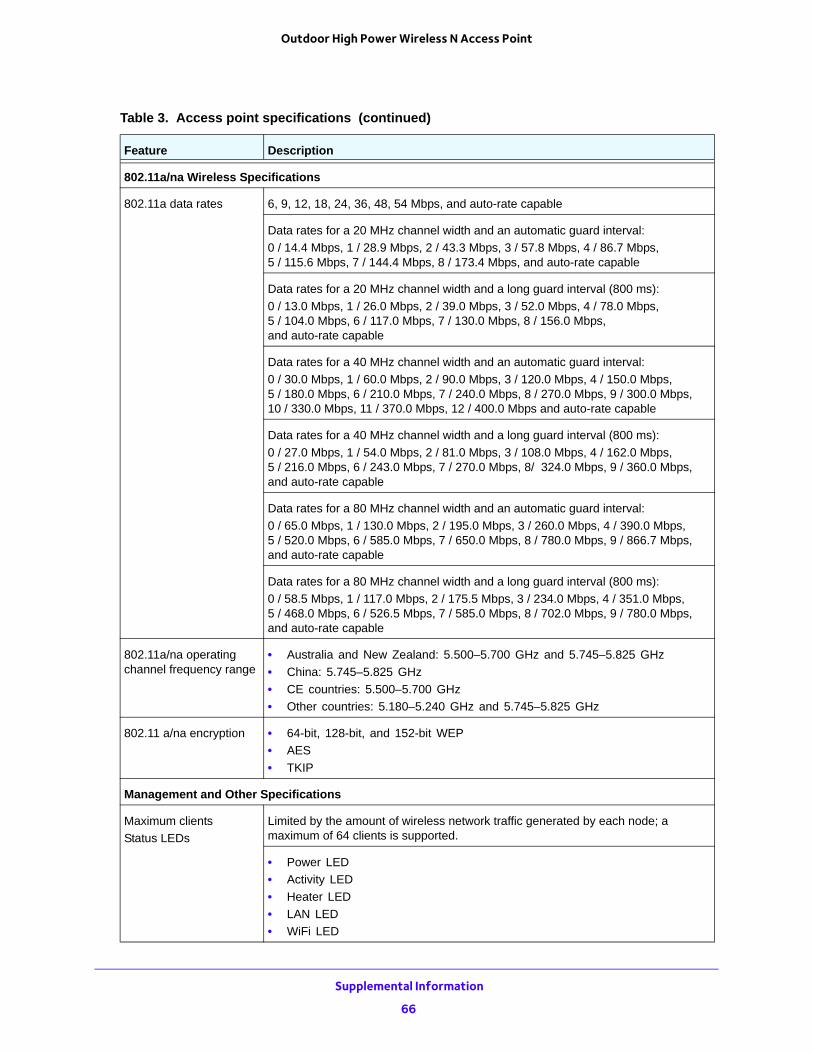
Outdoor High Power Wireless N Access Point
802.11a/na Wireless Specifications
802.11a data rates 6, 9, 12, 18, 24, 36, 48, 54 Mbps, and auto-rate capable
Data rates for a 20 MHz channel width and an automatic guard interval:
0 / 14.4 Mbps, 1 / 28.9 Mbps, 2 / 43.3 Mbps, 3 / 57.8 Mbps, 4 / 86.7 Mbps, 5 / 115.6 Mbps, 7 / 144.4 Mbps, 8 / 173.4 Mbps, and auto-rate capable
Data rates for a 20 MHz channel width and a long guard interval (800 ms):
0 / 13.0 Mbps, 1 / 26.0 Mbps, 2 / 39.0 Mbps, 3 / 52.0 Mbps, 4 / 78.0 Mbps, 5 / 104.0 Mbps, 6 / 117.0 Mbps, 7 / 130.0 Mbps, 8 / 156.0 Mbps, and auto-rate capable
Data rates for a 40 MHz channel width and an automatic guard interval:
0 / 30.0 Mbps, 1 / 60.0 Mbps, 2 / 90.0 Mbps, 3 / 120.0 Mbps, 4 / 150.0 Mbps, 5 / 180.0 Mbps, 6 / 210.0 Mbps, 7 / 240.0 Mbps, 8 / 270.0 Mbps, 9 / 300.0 Mbps, 10 / 330.0 Mbps, 11 / 370.0 Mbps, 12 / 400.0 Mbps and auto-rate capable
Data rates for a 40 MHz channel width and a long guard interval (800 ms):
0 / 27.0 Mbps, 1 / 54.0 Mbps, 2 / 81.0 Mbps, 3 / 108.0 Mbps, 4 / 162.0 Mbps, 5 / 216.0 Mbps, 6 / 243.0 Mbps, 7 / 270.0 Mbps, 8/ 324.0 Mbps, 9 / 360.0 Mbps, and auto-rate capable
Data rates for a 80 MHz channel width and an automatic guard interval:
0 / 65.0 Mbps, 1 / 130.0 Mbps, 2 / 195.0 Mbps, 3 / 260.0 Mbps, 4 / 390.0 Mbps, 5 / 520.0 Mbps, 6 / 585.0 Mbps, 7 / 650.0 Mbps, 8 / 780.0 Mbps, 9 / 866.7 Mbps, and auto-rate capable
Data rates for a 80 MHz channel width and a long guard interval (800 ms):
0 / 58.5 Mbps, 1 / 117.0 Mbps, 2 / 175.5 Mbps, 3 / 234.0 Mbps, 4 / 351.0 Mbps, 5 / 468.0 Mbps, 6 / 526.5 Mbps, 7 / 585.0 Mbps, 8 / 702.0 Mbps, 9 / 780.0 Mbps, and auto-rate capable
802.11a/na operating channel frequency range
• Australia and New Zealand: 5.500–5.700 GHz and 5.745–5.825 GHz
• China: 5.745–5.825 GHz
• CE countries: 5.500–5.700 GHz
• Other countries: 5.180–5.240 GHz and 5.745–5.825 GHz
802.11 a/na encryption • 64-bit, 128-bit, and 152-bit WEP
• AES
• TKIP
Management and Other Specifications
Maximum clients
Status LEDs
Limited by the amount of wireless network traffic generated by each node; a maximum of 64 clients is supported.
• Power LED
• Activity LED
• Heater LED
• LAN LED
• WiFi LED
Table 3. Access point specifications (continued)
Feature Description
Supplemental Information
66
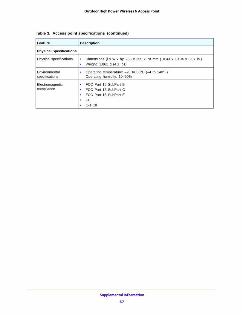
Outdoor High Power Wireless N Access Point
Physical Specifications
Physical specifications • Dimensions (l x w x h): 265 x 255 x 78 mm (10.43 x 10.04 x 3.07 in.)
• Weight: 1,861 g (4.1 lbs)
Environmental specifications
• Operating temperature: –20 to 60°C (–4 to 140°F)Operating humidity: 10–90%
Electromagnetic compliance
• FCC Part 15 SubPart B
• FCC Part 15 SubPart C
• FCC Part 15 SubPart E
• CE
• C-TICK
Table 3. Access point specifications (continued)
Feature Description
Supplemental Information
67