Embed Size (px)
Citation preview
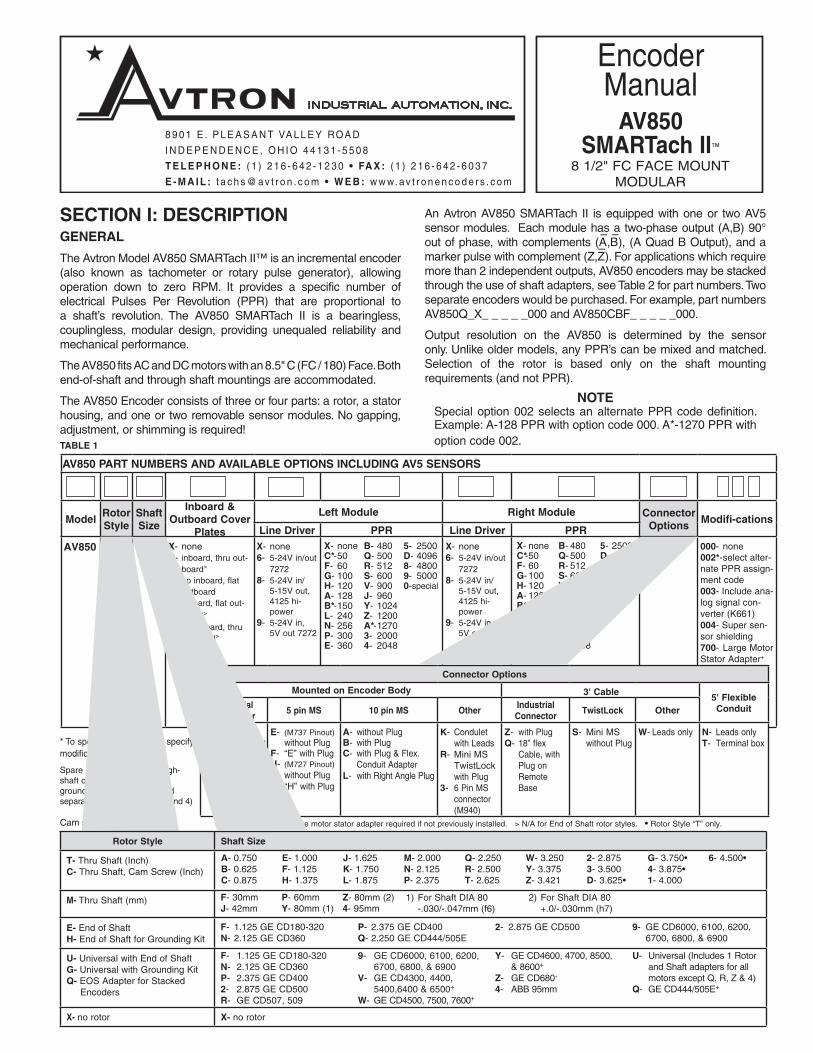
An Avtron AV850 SMARTach II is equipped with one or two AV5 sensor modules. Each module has a two-phase output (A,B) 90° out of phase, with complements (A
–,B–), (A Quad B Output), and a
marker pulse with complement (Z,Z–). For applications which require
more than 2 independent outputs, AV850 encoders may be stacked through the use of shaft adapters, see Table 2 for part numbers. Two separate encoders would be purchased. For example, part numbers AV850Q_X_ _ _ _ _000 and AV850CBF_ _ _ _ _000.
Output resolution on the AV850 is determined by the sensor only. Unlike older models, any PPR’s can be mixed and matched. Selection of the rotor is based only on the shaft mounting requirements (and not PPR).
NOTESpecial option 002 selects an alternate PPR code definition. Example: A-128 PPR with option code 000. A*-1270 PPR with option code 002.
SECTION I: DESCRIPTIONGENERAL
The Avtron Model AV850 SMARTach II™ is an incremental encoder (also known as tachometer or rotary pulse generator), allowing operation down to zero RPM. It provides a specific number of electrical Pulses Per Revolution (PPR) that are proportional to a shaft’s revolution. The AV850 SMARTach II is a bearingless, couplingless, modular design, providing unequaled reliability and mechanical performance.
The AV850 fits AC and DC motors with an 8.5" C (FC / 180) Face. Both end-of-shaft and through shaft mountings are accommodated.
The AV850 Encoder consists of three or four parts: a rotor, a stator housing, and one or two removable sensor modules. No gapping, adjustment, or shimming is required!
8 9 0 1 E . P L E A S A N T VA L L E Y ROA D
I N D E P E N D E N C E , O H I O 4 4 1 3 1 - 5 5 0 8
T E L E P H O N E : ( 1 ) 2 1 6 - 6 4 2 - 1 2 3 0 • FA X : ( 1 ) 2 1 6 - 6 4 2 - 6 0 3 7
E - M A I L : t a c h s @ av t r o n . c o m • W E B : w w w. av t r o n e n c o d e r s . c o m
INDUSTRIAL AUTOMATION, INC.
EncoderManual
AV850SMARTach II™
8901 E. PLEASANT VALLEY RD., INDEPENDENCE, OH 44131, U.S.A. • (1) 216-642-1230 • FAX (1) 216-642-6037 • www.avtronencoders.com
INDUSTRIAL AUTOMATION, INC.
REV: 11-05-1010
8 1/2" FC FACE MOUNT MODULAR
* To specify this PPR, also specify modification code 002.
Spare sensors, rotors, through-shaft cover plates, and shaft grounding kits can be ordered separately. (See Tables 2, 3, and 4)
Cam screw rotors patented.
TABLE 1
AV850 PART NUMBERS AND AVAILABLE OPTIONS INCLUDING AV5 SENSORS
ModelRotor Style
Shaft Size
Inboard & Outboard Cover
Plates
Left Module Right Module Connector Options
Modifi-cationsLine Driver PPR Line Driver PPR
AV850 X- noneB- inboard, thru out- board>
F- no inboard, flat outboardN- inboard, flat out-
board>
T- no inboard, thru outboard>
X- none6- 5-24V in/out 72728- 5-24V in/ 5-15V out, 4125 hi- power9- 5-24V in, 5V out 7272
X- none6- 5-24V in/out 72728- 5-24V in/ 5-15V out, 4125 hi- power9- 5-24V in, 5V out 7272
000- none002*- select alter-nate PPR assign-ment code 003- Include ana-log signal con-verter (K661) 004- Super sen-sor shielding 700- Large Motor Stator Adapter+
X- noneC*- 50F- 60G- 100H- 120A- 128B*- 150L- 240N- 256P- 300E- 360
B- 480Q- 500R- 512S- 600V- 900J- 960Y- 1024Z- 1200A*- 12703- 20004- 2048
5- 2500D- 40968- 48009- 50000-special
X- noneC*- 50F- 60G- 100H- 120A- 128B*- 150L- 240N- 256P- 300E- 360
B- 480Q- 500R- 512S- 600V- 900J- 960Y- 1024Z- 1200A*- 12703- 20004- 2048
5- 2500D- 40968- 48009- 50000-special
SMARTach II™ is a trademark of Avtron Industrial Automation, Inc.Features and specifications subject to change without notice.
Avtron standard warranty applies. All dimensions are in inches (mm).
0.19 (4.83)
8.50158.5035
DIA
(215.938)(215.989)
DIA
DRAIN PLUG 1/8 - 27 N.P.T.
NOTE: If the pulse generator will beexposed to water spray, the bottom1/8" pipe plug should be removed.
2.54(64.52)
1.29(32.8)
0.24(6.10)
5FT (1524.0) MIN
45∞
0.562 (14.275) DIA - 4 HOLESEQUALLY SPACED ON A7.250 (184.150) DIA.
4.38(111.25)
9.00 (228.60) DIA
LED Indicator
STANDARD:1/2-14 NPT
COVER PLATESINGLE OUTPUTONLY
OPTION “P”, “G”PLUG-IN INDUSTRIAL CONNECTOR
ALTERNATES SHOWN BELOW
OPTION “N”FLEXIBLE WATER-PROOF CONDUIT
RIGHTMODULELEFT
MODULE
0.53 (13.5)
3.83 (97.3) 4.66 (118.4)
OPTION "R"
OPTION "3"6 PIN MS
CONNECTOR (M940)
OPTION "K"
2.80 (71.1)
3.06(11.7)
1.53(38.9)
OPTION "A" BULKHEAD CONNECTOR ONLY
OPTION "B"WITH MATING PLUG & CABLE GROMMET
1.97(50.0) 3.67 (93.2)
Assembled
0.53(13.5)
1.66(42.2)
OPTION "C"
3.25(82.6)
OPTION "E" & "H" BULKHEAD CONNECTOR ONLY
OPTION "F" & "J"WITH MATING PLUG
0.53(13.5)
1.42(36.0)
3.08 (78.2)Assembled
1.85(47.0)
1.42(36.0)
OPTION "L"
0.53(13.5)
2.09(53.0)
1.97(50.0)
3.87 (98.3)
OPTION "S" 0.53(13.5)
36.50 (927.0) MIN
OPTION "W"0.53
(13.5)
36.50 (927.0) MIN
OPTION "T"
Terminal Block
2.00(50.8)
4.31(109.5)
1.16(29.3)
1.16(29.3)
0.312 (7.92)4 Holes
Box is 3.12 (79.25) Deep
0.53(13.5)
4.750 (120.6)
5.50 (140.0)
5FT (1524.0) MIN
OPTION "X" SURFACE MOUNT CONNECTOR ONLY
OPTION "Z"WITH MATING PLUG
0.53(13.5)
0.41 (10.5)
1.20(30.5)
4.31(109.5)
1.574(40.0)
2.13(54.0)
3.228 (82.0)
3.70 (94.0)
0.18(4.5)
0.217 (5.50)4 Holes
36.50 (927.0) MIN
5.641(143.3)
5.641(143.3)
1.072(27.2)
MOTOR SIDE
OPTION “TA-T9, MA-M9”SET SCREW STYLE ROTOR
5.641(143.3)
1.011(25.7)
MOTORSIDE
OPTION“CA-C9, UA-U9,
GA-G9”CAM SCREW
STYLE ROTOR
PLUG WITH CONDUIT ADAPTER
OPTION “Q”REMOTE BASE FOR BALDOR TEFC/TENV
MOTORS
18.00[457.2]
MIN
0.30[7.6]
0.81[20.6]
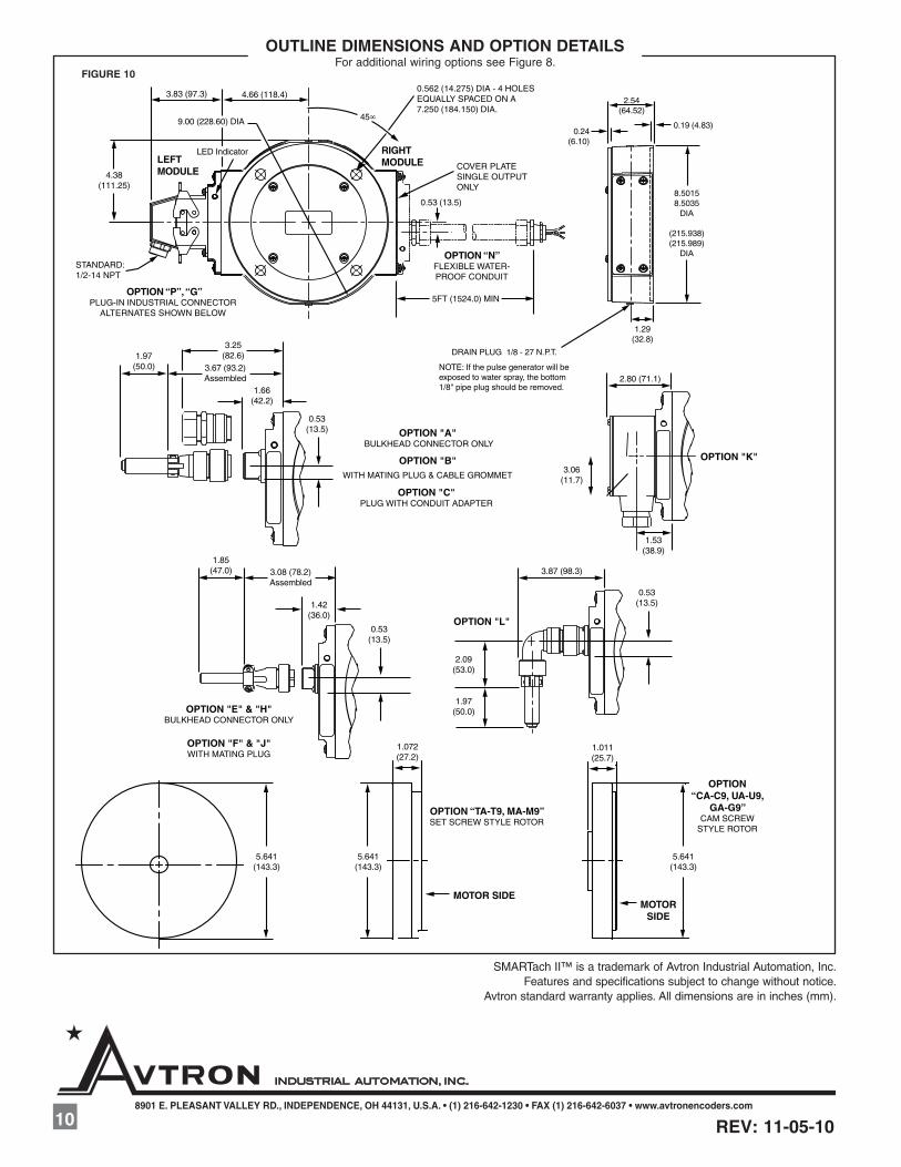
OUTLINE DIMENSIONS AND OPTION DETAILS For additional wiring options see Figure 8.
FIGURE 10
Rotor Style Shaft Size
T- Thru Shaft (Inch)C- Thru Shaft, Cam Screw (Inch)
M- Thru Shaft (mm)
E- End of ShaftH- End of Shaft for Grounding Kit
U- Universal with End of ShaftG- Universal with Grounding KitQ- EOS Adapter for Stacked Encoders
X- no rotor X- no rotor
A- 0.750B- 0.625C- 0.875
E- 1.000F- 1.125H- 1.375
J- 1.625K- 1.750L- 1.875
M- 2.000N- 2.125P- 2.375
Q- 2.250R- 2.500T- 2.625
W- 3.250Y- 3.375Z- 3.421
2- 2.8753- 3.500D- 3.625•
G- 3.750•4- 3.875•1- 4.000
6- 4.500•
F- 30mmJ- 42mm
P- 60mmY- 80mm (1)
Z- 80mm (2)4- 95mm
F- 1.125 GE CD180-320N- 2.125 GE CD360
P- 2.375 GE CD400Q- 2.250 GE CD444/505E
2- 2.875 GE CD500 9- GE CD6000, 6100, 6200, 6700, 6800, & 6900
1) For Shaft DIA 80 -.030/-.047mm (f6)
2) For Shaft DIA 80 +.0/-.030mm (h7)
Connector Options
Mounted on Encoder Body 3' Cable5' Flexible ConduitIndustrial
Connector5 pin MS 10 pin MS Other
Industrial Connector
TwistLock Other
P- with PlugG- (NorthstarTM Pinout) with Plug
E- (M737 Pinout) without PlugF- “E” with PlugH- (M727 Pinout) without PlugJ- “H” with Plug
A- without PlugB- with PlugC- with Plug & Flex. Conduit AdapterL- with Right Angle Plug
K- Condulet with LeadsR- Mini MS TwistLock with Plug3- 6 Pin MS connector (M940)
Z- with PlugQ- 18” flex Cable, with Plug on Remote Base
S- Mini MS without Plug
W- Leads only N- Leads onlyT- Terminal box
+ Large motor stator adapter required if not previously installed. > N/A for End of Shaft rotor styles. • Rotor Style “T” only.
F- 1.125 GE CD180-320N- 2.125 GE CD360P- 2.375 GE CD4002- 2.875 GE CD500R- GE CD507, 509
9- GE CD6000, 6100, 6200, 6700, 6800, & 6900V- GE CD4300, 4400, 5400,6400 & 6500+
W- GE CD4500, 7500, 7600+
Y- GE CD4600, 4700, 8500, & 8600+
Z- GE CD680+
4- ABB 95mm
U- Universal (Includes 1 Rotor and Shaft adapters for all motors except Q, R, Z & 4)Q- GE CD444/505E+

FACE
SETSCREW
HUB
MOUNTINGACCESSORY
SEAL PLATEAND SHIELD
MOTOR
V-RINGSEAL
MOTORSHAFT
HOUSINGSTATOR
0.584 [14.8mm] from seal plateand shield (+/-0.100" [+/-2.5mm])
3/16" Hex Wrench (cam screw rotors only) 9/16" Wrench (end-of-shaft rotors only)
Optional: A35226 Gauge or A25355 M285/AV850 Rotor Gauge Block Inboard Through-Shaft Seal Plate Outboard Through-Shaft Seal Plate Kit Silicone Lubricant or 20 Weight Machine OilDead Blow Hammer Large Frame Adapter Kit (Modification “700”) AV850 Shield Kit (A35355)
(OPTIONAL) LARGE MOTOR STATOR ADAPTER INSTAL-LATION (Modification “700”)
For large frame GE CD motors Avtron offers a frame adapter to add an 8.5" C-face to the motor. To install the flange adapter:
1. Remove all existing adapters on the non-drive end of the motor.
2. Clean the motor flange.
3. Using the supplied hardware, bolt the flange adapter in place (see Figure 1).
4. Apply anti-seize to the frame adapter C-face flange.
(OPTIONAL) INBOARD SEAL PLATE INSTALLATION (Cover Plate “B” & “N”):
For installations where the AV850 will be mounted to an open frame flange adapter, or other installation where the inner surface of the AV850 will not form a seal with the rear end bell of the motor, Avtron offers inboard, through-shaft seal plate kits. These kits include a cover plate and seal. See Table 3 for part numbers. To install the inboard through-shaft seal plate kit:
1. Verify all components fit the motor shaft (rotor, V-ring seal, and seal plate.
2. Slide V-ring seal onto motor shaft.
3. Apply a light coating of silicone lubricant or medium grade machine oil to the outward face of the seal.
4. Use the seal plate to push the seal on the shaft; stop when the seal plate contacts the motor face. Remove the seal plate and push
The AV5 removable sensor assembly has a diagnostic package that includes Adaptive Electronics and a Fault-Check output. With this package, the SMARTach II can maintain itself, and let you know if there is a problem before the problem causes unscheduled downtime.
SECTION II: INSTALLATIONGENERALThe motor must comply with NEMA MG1 for dimensions, face runout, and shaft runout. Axial float or endplay must be less than +/-0.100" inch.
CAUTIONDo not strike the encoder or rotor at any time. Damage will result and the warranty will be void. At installation, clean and remove paint and burrs from motor shaft and mounting face. Apply anti-seize compound (supplied) to each except cam screw rotors.
INSTALLATION HARDWAREInstallation hardware required is attached to each assembly.
Equipment needed for installationSupplied:
AV850 Encoder 1. Washer, Spring Lock 1/2 (4) 2. Hex Hd. Cap Screw 1/2-13 x 3.00 (4)
Rotor 1. Rotor Installation Hardware Kit 2. Anti-Seize Compound (copper) 3. Thread Locker (blue)
Not Supplied:3/4" Wrench Phillips Screwdriver7/16" Nut Driver Dial IndicatorVernier Caliper 3/32" Hex Wrench (T-Handle style) (thru shaft rotors only)
9
MOTOR
V-RINGSEAL
MOTORSHAFT
0.584 [14.8mm] from seal plate and shield. (+/-0.100" [+/-2.5mm])
OPTIONAL OUTBOARD SEAL PLATE
MOTOR
LARGE FRAMEADAPTER
STATORHOUSING
MOTOR SHAFT
CAM SCREWUNIVERSALROTOR
SHIELD PLATE
SHAFT ADAPTER
0.584 [14.8mm] fromshield and seal plate
FIGURE 1
SET SCREW STYLE “TA-T9,
MA-M9”
CAM SCREW STYLE “CA-C9,
GA-G9”
ACCESSORY MOUNTING FACE
0.584 +/-0.100" [14.8mm +/-2.5mm]
MOTOR
OPTIONAL INBOARD SHIELD AND/OR
SEAL PLATE
FIGURE 2 FIGURE 3
2
0.19 (4.83)
8.50158.5035
DIA
(215.938)(215.989)
DIA
DRAIN PLUG 1/8 - 27 N.P.T.
NOTE: If the pulse generator will beexposed to water spray, the bottom1/8" pipe plug should be removed.
2.54(64.52)
1.29(32.8)
0.24(6.10)
5FT (1524.0) MIN
45∞
0.562 (14.275) DIA - 4 HOLESEQUALLY SPACED ON A7.250 (184.150) DIA.
4.38(111.25)
9.00 (228.60) DIA
LED Indicator
STANDARD:1/2-14 NPT
COVER PLATESINGLE OUTPUTONLY
OPTION “P”, “G”PLUG-IN INDUSTRIAL CONNECTOR
ALTERNATES SHOWN BELOW
OPTION “N”FLEXIBLE WATER-PROOF CONDUIT
RIGHTMODULELEFT
MODULE
0.53 (13.5)
3.83 (97.3) 4.66 (118.4)
OPTION "R"
OPTION "3"6 PIN MS
CONNECTOR (M940)
OPTION "K"
2.80 (71.1)
3.06(11.7)
1.53(38.9)
OPTION "A" BULKHEAD CONNECTOR ONLY
OPTION "B"WITH MATING PLUG & CABLE GROMMET
1.97(50.0) 3.67 (93.2)
Assembled
0.53(13.5)
1.66(42.2)
OPTION "C"
3.25(82.6)
OPTION "E" & "H" BULKHEAD CONNECTOR ONLY
OPTION "F" & "J"WITH MATING PLUG
0.53(13.5)
1.42(36.0)
3.08 (78.2)Assembled
1.85(47.0)
1.42(36.0)
OPTION "L"
0.53(13.5)
2.09(53.0)
1.97(50.0)
3.87 (98.3)
OPTION "S" 0.53(13.5)
36.50 (927.0) MIN
OPTION "W"0.53
(13.5)
36.50 (927.0) MIN
OPTION "T"
Terminal Block
2.00(50.8)
4.31(109.5)
1.16(29.3)
1.16(29.3)
0.312 (7.92)4 Holes
Box is 3.12 (79.25) Deep
0.53(13.5)
4.750 (120.6)
5.50 (140.0)
5FT (1524.0) MIN
OPTION "X" SURFACE MOUNT CONNECTOR ONLY
OPTION "Z"WITH MATING PLUG
0.53(13.5)
0.41 (10.5)
1.20(30.5)
4.31(109.5)
1.574(40.0)
2.13(54.0)
3.228 (82.0)
3.70 (94.0)
0.18(4.5)
0.217 (5.50)4 Holes
36.50 (927.0) MIN
5.641(143.3)
5.641(143.3)
1.072(27.2)
MOTOR SIDE
OPTION “TA-T9, MA-M9”SET SCREW STYLE ROTOR
5.641(143.3)
1.011(25.7)
MOTORSIDE
OPTION“CA-C9, UA-U9,
GA-G9”CAM SCREW
STYLE ROTOR
PLUG WITH CONDUIT ADAPTER
OPTION “Q”REMOTE BASE FOR BALDOR TEFC/TENV
MOTORS
18.00[457.2]
MIN
0.30[7.6]
0.81[20.6]
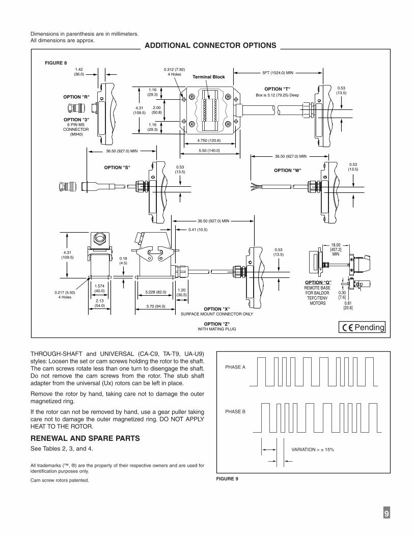
ADDITIONAL CONNECTOR OPTIONS
Dimensions in parenthesis are in millimeters. All dimensions are approx.
FIGURE 8
Pending
THROUGH-SHAFT and UNIVERSAL (CA-C9, TA-T9, UA-U9) styles: Loosen the set or cam screws holding the rotor to the shaft. The cam screws rotate less than one turn to disengage the shaft. Do not remove the cam screws from the rotor. The stub shaft adapter from the universal (Ux) rotors can be left in place.
Remove the rotor by hand, taking care not to damage the outer magnetized ring.
If the rotor can not be removed by hand, use a gear puller taking care not to damage the outer magnetized ring. DO NOT APPLY HEAT TO THE ROTOR.
RENEWAL AND SPARE PARTSSee Tables 2, 3, and 4.
All trademarks (™, ®) are the property of their respective owners and are used for identification purposes only.
Cam screw rotors patented.
ROTOR MOUNTING(Through Shaft Shown)
FIGURE 4
OPTIONAL LARGE STATOR ADAPTER
FIGURE 9
VARIATION > ± 15%
PHASE A
PHASE B
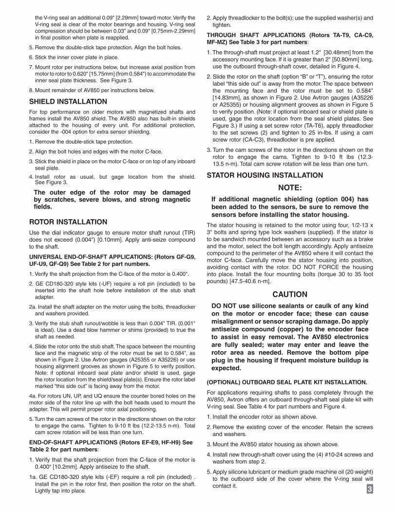
the V-ring seal an additional 0.09" [2.29mm] toward motor. Verify the V-ring seal is clear of the motor bearings and housing. V-ring seal compression should be between 0.03" and 0.09" [0.75mm-2.29mm] in final position when plate is reapplied.
5. Remove the double-stick tape protection. Align the bolt holes.
6. Stick the inner cover plate in place.
7. Mount rotor per instructions below, but increase axial position from motor to rotor to 0.620" [15.75mm] (from 0.584") to accommodate the inner seal plate thickness. See Figure 3.
8. Mount remainder of AV850 per instructions below.
SHIELD INSTALLATIONFor top performance on older motors with magnetized shafts and frames install the AV850 shield. The AV850 also has built-in shields attached to the housing of every unit. For additional protection, consider the -004 option for extra sensor shielding.
1. Remove the double-stick tape protection.
2. Align the bolt holes and edges with the motor C-face.
3. Stick the shield in place on the motor C-face or on top of any inboard seal plate.
4. Install rotor as usual, but gage location from the shield. See Figure 3.
The outer edge of the rotor may be damaged by scratches, severe blows, and strong magnetic fields.
ROTOR INSTALLATIONUse the dial indicator gauge to ensure motor shaft runout (TIR) does not exceed (0.004") [0.10mm]. Apply anti-seize compound to the shaft.
UNIVERSAL END-OF-SHAFT APPLICATIONS: (Rotors GF-G9, UF-U9, QF-Q9) See Table 2 for part numbers.
1. Verify the shaft projection from the C-face of the motor is 0.400".
2. GE CD180-320 style kits (-UF) require a roll pin (included) to be inserted into the shaft hole before installation of the stub shaft adapter.
2a. Install the shaft adapter on the motor using the bolts, threadlocker and washers provided.
3. Verify the stub shaft runout/wobble is less than 0.004" TIR. (0.001" is ideal). Use a dead blow hammer or shims (provided) to true the shaft as needed.
4. Slide the rotor onto the stub shaft. The space between the mounting face and the magnetic strip of the rotor must be set to 0.584", as shown in Figure 2. Use Avtron gauges (A25355 or A35226) or use housing alignment grooves as shown in Figure 5 to verify position. Note: if optional inboard seal plate and/or shield is used, gage the rotor location from the shield/seal plate(s). Ensure the rotor label marked “this side out” is facing away from the motor.
4a. For rotors UN, UP, and UQ ensure the counter bored holes on the motor side of the rotor line up with the bolt heads used to mount the adapter. This will permit proper rotor axial positioning.
5. Turn the cam screws of the rotor in the directions shown on the rotor to engage the cams. Tighten to 9-10 ft lbs (12.2-13.5 n-m). Total cam screw rotation will be less than one turn.
END-OF-SHAFT APPLICA TIONS (Rotors EF-E9, HF-H9) See Table 2 for part numbers:
1. Verify that the shaft projection from the C-face of the motor is 0.400" [10.2mm]. Apply antiseize to the shaft.
1a. GE CD180-320 style kits (-EF) require a roll pin (included) . Install the pin in the rotor first, then position the rotor on the shaft. Lightly tap into place.
2. Apply threadlocker to the bolt(s); use the supplied washer(s) and tighten.
THROUGH SHAFT APPLI CA TIONS (Rotors TA-T9, CA-C9, MF-MZ) See Table 3 for part numbers:
1. The through-shaft must project at least 1.2" [30.48mm] from the accessory mounting face. If it is greater than 2" [50.80mm] long, use the outboard through-shaft cover, detailed in Figure 4.
2. Slide the rotor on the shaft (option “B” or “T”), ensuring the rotor label “this side out” is away from the motor. The space between the mounting face and the rotor must be set to 0.584" [14.83mm], as shown in Figure 2. Use Avtron gauges (A35226 or A25355) or housing alignment grooves as shown in Figure 5 to verify position. (Note: if optional inboard seal or shield plate is used, gage the rotor location from the seal shield plates. See Figure 3.) If using a set screw rotor (TA-T6), apply threadlocker to the set screws (2) and tighten to 25 in-lbs. If using a cam screw rotor (CA-C3), threadlocker is pre applied.
3. Turn the cam screws of the rotor in the directions shown on the rotor to engage the cams. Tighten to 9-10 ft lbs (12.3- 13.5 n-m). Total cam screw rotation will be less than one turn.
STATOR HOUSING IN STALL ATION
NOTE:If additional magnetic shielding (option 004) has been added to the sensors, be sure to remove the sensors before installing the stator housing.
The stator housing is retained to the motor using four, 1/2-13 x 3" bolts and spring type lock washers (supplied). If the stator is to be sandwich mounted between an accessory such as a brake and the motor, select the bolt length accordingly. Apply antiseize compound to the perimeter of the AV850 where it will contact the motor C-face. Carefully move the stator housing into position, avoiding contact with the rotor. DO NOT FORCE the housing into place. Install the four mounting bolts (torque 30 to 35 foot pounds) [47.5-40.6 n-m].
CAUTIONDO NOT use silicone sealants or caulk of any kind on the motor or encoder face; these can cause misalignment or sensor scraping damage. Do apply antiseize compound (copper) to the encoder face to assist in easy removal. The AV850 electronics are fully sealed; water may enter and leave the rotor area as needed. Remove the bottom pipe plug in the housing if frequent moisture buildup is expected.
(OPTIONAL) OUTBOARD SEAL PLATE KIT INSTALLATION.
For applications requiring shafts to pass completely through the AV850, Avtron offers an outboard through-shaft seal plate kit with V-ring seal. See Table 4 for part numbers and Figure 4.
1. Install the encoder rotor as shown above.
2. Remove the existing cover of the encoder. Retain the screws and washers.
3. Mount the AV850 stator housing as shown above.
4. Install new through-shaft cover using the (4) #10-24 screws and washers from step 2.
5. Apply silicone lubricant or medium grade machine oil (20 weight) to the outboard side of the cover where the V-ring seal will contact it. 38
Imperial (US) Sizes
Shaft Bore
Inboard Covers
Flat Thru-ShaftCover
MagneticShieldSeal ONLY Seal ONLY
-AN
-NA--NA--NA-
-NA--NA--NA-
-NA--NA-
A35355
A35355A35355A35355
A35355A35355A35355A35355A35355A35355A35355A35355A35355
A35355A35355
A35355A35355A35355--AN-8091742-30243A43903BAC-41513BACAT-51903BAT"057.0
4181741-11262A4181741-30243A51513B*BCBT-51903BBT"526.0-AN--AN-1391743-30243ACC-41513BCCCT-51903BCT"578.0
0091742-11262A0091744-30243AEC-41513BECET-51903BET"000.13781743-11262A3781745-30243AFC-41513BFCFT-51903BFT"521.1
4881744-11262A4881747-30243AHC-41513BHCHT-51903BHT"573.11091745-11262A1091748-30243AJC-41513BJCJT-51903BJT"526.1
-AN--AN-20917401-30243AKC-41513BKCKT-51903BKT"057.12091746-11262A20917411-30243ALC-41513BLCLT-51903BLT"578.16881747-11262A68817421-30243AMC
-41513BMCMT-51903BMT"000.2
3091748-11262A30917431-30243ANC-41513BNCNT-51903BNT"521.240917421-11262A40917451-30243APC-41513BPCPT-51903BPT"573.23091748-11262A30917441-30243AQC-41513BQCQT-51903BQT"052.25091749-11262A50917461-30243ARC-41513BRCRT-51903BRT"005.2
-AN--AN-50917452-30243ATC-41513BTCTT-51903BTT"526.2-AN--AN-70917491-30243AWC-41513BWCWT-51903BWT"052.3-AN--AN-60917402-30243AYC-41513BYCYT-51903B YT"573.3-AN--AN-60917412-30243AZC-41513BZCZT-51903BZT"124.3
58817401-11262A58817471-30243A2C-41513B2C2T-51903B2T"578.201917411-11262A01917422-30243A3C-41513B3C3T-51903B3T"005.3
-AN--AN-34917432-30243A-AN--AN-4T-51903B4T"578.3-AN--AN--AN-42-30243A-AN--AN-6T-51903B6T"005.4
Metric Sizes-AN--AN-9391746-30243A43903B-AN--AN-MF-51903BFMmm03-AN--AN-1091749-30243A-AN--AN--51903BJMmm24-AN--AN-40917451-30243A-AN--AN--51903BPMmm06-AN--AN-70917481-30243A-AN--AN--51903BYMmm08-AN--AN-70917481-30243A-AN--AN--51903BZM
JMPMYMZMmm08
Outboard Covers
Set Screw
Cam Screw
Rotor PartRotor PartRotor Code
Rotor Code
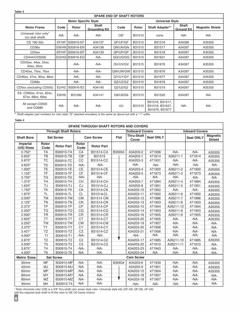
Through Shaft RotorsSPARE THROUGH SHAFT ROTORS AND COVERS
Set Screw
Cam Screw
95mm
3.625"
3.750"
4.000"
TD
TG B30915-TG
B30915-T1T1
B30915-TD
M4 B30915-T4
-AN-
-AN- -AN- -AN- -AN- -AN- -AN- -AN-
-AN-
-AN- -AN- -NA- -NA- -AN- -AN-
-AN-
-AN- -AN- -AN- -AN- -AN- -AN-
-AN--AN--AN--AN--AN--AN-
A35355
Table 4
SPARE END OF SHAFT ROTORS
Motor Specific Style Universal Style
Motor Frame Code RotorShaft
Grounding KitCode Rotor Shaft Adapter**
Shaft Ground Kit
Magnetic Shield
Universal rotor only* (no stub shaft)
-NA- -NA- -NA- CB* B31515 none -NA- -NA-
CD 180-32x EF/HF B30916-EF A34137 QF/UF/GF B31515 B31516 A34396 A35355
CD36x EN/HN B30916-EN A34138 QN/UN/GN B31515 B31517 A34397 A35355
CD4xx EP/HP B30916-EP A34139 QP/UP/GP B31515 B31518 A34397 A35355
CD444/CD505E EQ/HQ B30916-EQ -NA- QQ/UQ/GQ B31515 B31631 A34397 A35355
CD43xx, 44xx, 54xx, 64xx, 65xx
-NA- -NA- QV/UV/GV B31515 B31676 A34397 A35355
CD45xx, 75xx, 76xx -NA- -NA- QW/UW/GW B31515 B31676 A34397 A35355
CD46xx, 47xx, 85xx, 86xx -NA- -NA- QY/UY/GY B31515 B31677 A34397 A35355
CD68x -NA- -NA- QZ/UZ/GZ B31515 B31678 A34397 A35355
CD5xx (excluding CD505) E2/H2 B30916-E2 A34140 Q2/U2/G2 B31515 B31519 A34397 A35355
E9- CD60xx, 61xx, 62xx, 67xx, 68xx, 69xx
E9/H9 B31092 A34141 Q9/U9/G9 B31515 B31520 A34397 -NA-
All except CD505 and CD680
-NA- -NA- -NA- UU B31515B31516, B31517, B31518, B31637, B31676, B31677
-NA- -NA-
** Shaft adapter part numbers for rotor style “Q” (stacked encoders) is the same as above but with a “-1” suffix.
* Note Universal rotor (CB) is a 5/8" thru-shaft cam screw style rotor. Universal style kits (GF-G9, QF-Q9, UF-U9) add the required stub shaft to fit the rotor to GE CD frame motors.
Table 3

6. Slide the V-ring seal onto the shaft, and ensure that it is compressed against the cover. See installation Figure 4.
(OPTIONAL) SHAFT GROUNDING KIT INSTALLATION (Rotors “FA-F9”, “GA-G9”)
Refer to separate Shaft Grounding Kit Instructions (M190-AV850)
(OPTIONAL) CHECK ROTOR POSITION 1. Remove a sensor or blank side cover plate.
2. Verify the rotor magnetic stripe is aligned with the grooves (see Figure 5).
3. Replace the sensor or side cover plate.
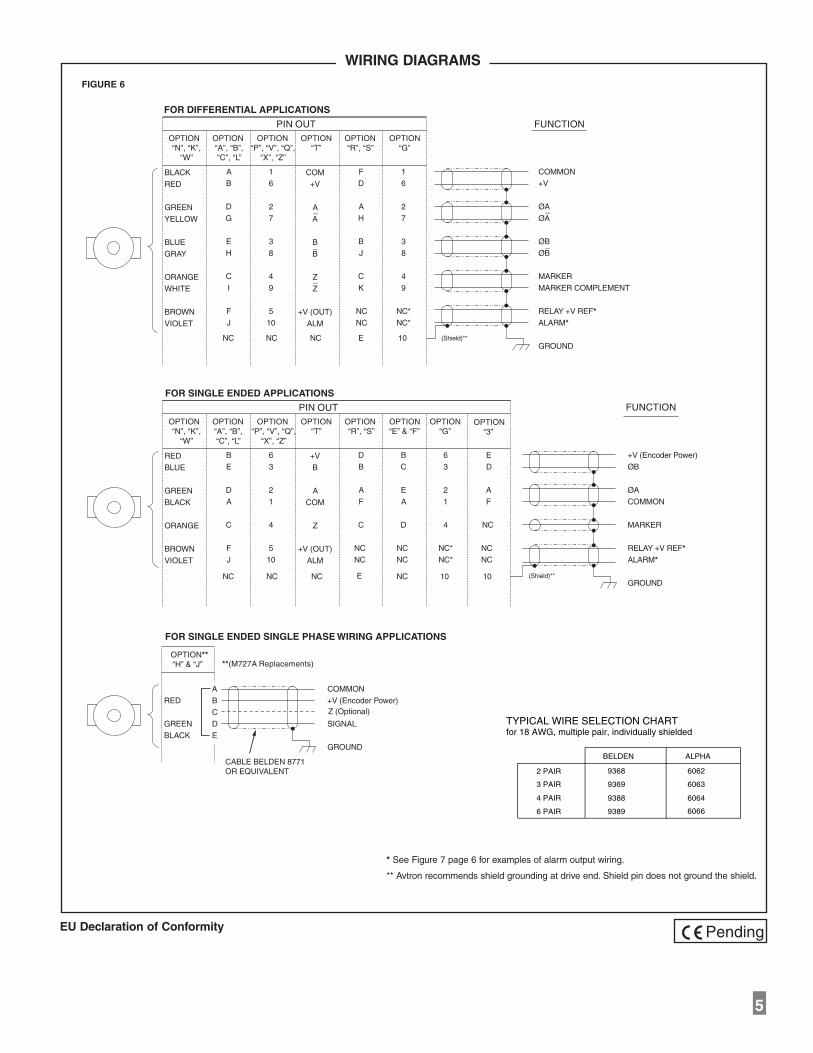
WIRING INSTRUCTIONS
CAUTIONRemove power before wiring.
Wiring diagrams are shown in Figure 6 and 7.
For bidirectional operation of the encoder, proper phasing of the two output channels is important. Phase A channel leads phase B channel for clockwise shaft rotation as viewed from the anti-drive or accessory end of the motor (encoder mounting end).
Wiring option “G” provides a pinout compatible with NorthstarTM
encoders, with a cable shield connection on pin 10. Note that this option does not ground the shield; Avtron still recommends grounding the shield at the drive end of the cable for all wiring options.
CORRECTIVE ACTION FOR PHASE REVERSAL1) Remove Power.2) Exchange wires on cable, either at encoder cable end or at speed controller end (but not both).
7
a) Single Ended 2 Phase Wiring (see wiring diagram) Exchange A and B at the use end of the wires. b) Differential 2 Phase Wiring (see wiring diagram) Exchange either A with A– in the phase A pair OR B with B– in the phase B pair but NOT both.3) Apply power and verify encoder feedback is correct.
Interconnecting cables specified in the WIRE SELECTION CHART in Figure 6 are based on typical applications. Refer to the system drawing for specific cable requirements where applicable.
Physical properties of cable such as abrasion, temperature, tensile strength, solvents, etc., are dictated by the specific application. General electrical requirements are: stranded copper, 22 thru 16
gauge (Industrial EPIC Connector options can use 14-20 AWG), each wire pair individually shielded with braid or foil with drain wire, 0.05 uF maximum total mutual or direct capacitance, outer sheath insulator, 1,000 ft. max. See WIRE SELECTION CHART in Figure 6 for some suggested cables.
See Figure 7 for examples of alarm output wiring.
NOTEWhen using the industrial connector (“G”, “P”, “V”, “X”, or “Z” options), the minimum wire size is 20 gage, and 20 gage (only) wire ends must be tinned with solder before connection at the screw terminals.
SECTION III: MAINTENANCE
GENERALThis section describes routine maintenance for the Avtron AV850 Encoder. For support, contact Avtron’s field service department at 216-642-1230. For emergency after hours service contact us at 216-641-8317.
The AV850 SMARTach II circuitry includes a diagnostic package that includes Adaptive Electronics and a Fault-Check output.
ADAPTIVE ELECTRONICSA perfect duty cycle consists of a waveform whose “high” and “low” conditions are of the same duration (50%/50%).
The AV850 adaptive electronics extends the life of the AV850 by constantly monitoring and correcting duty cycle over time.
FAULT-CHECKAfter power-up and the rotor position is checked by the sensor, the Fault-Check LED will turn green.
If the adaptive electronics reach their adjustment limit for any reason, the Fault-Check alarm and LED will notify the drive and operator of an impending failure. The LED will turn red if the Adaptive Electronics reach their adjustment limit. This output occurs before an actual failure, allowing steps to be taken to replace the unit before it causes unscheduled downtime. Fault-Check annunciation is available as an “alarm” output through the connector and as an integral LED.
TROUBLESHOOTING:
If the drive indicates a loss of encoder/tach fault and the AV850 fault-check LED is not illuminated, check the encoder power sup-ply. If power is present, check polarity; one indicator of reversed power supply is that all outputs will be high at the same time. If the drive indicates encoder fault, but the LED shows GREEN, then check the wiring between the drive and the encoder. If the wiring appears correct and in good shape, test the wiring by replacing the AV5 sensor module. If the new module shows GREEN, and the drive still shows encoder loss/tach fault, then the wiring is faulty and should be repaired or replaced.
If the alarm output and/or LED indicate a fault (RED):
1. Remove an end sensor plate or the second sensor, and use the built-in gauge to check the location of the rotor (see Figure 2.1). Ensure the label marked “This side out” is facing away from the motor.
2. Remove the AV5 sensor from the housing. Clean the housing mounting surface for the AV5 sensor and the AV850 housing. Ensure the AV5 sensor is directly mounted on the AV850 hous-ing, with no sealant, gasketing, or other materials, and is firmly bolted in place.
If the alarm output and/or LED indicate a fault (RED) on a properly mounted AV5 sensor and the rotor is properly located, replace the AV5 sensor.
An oscilloscope can also be used to verify proper output of the AV850 encoder at the encoder connector itself and at the drive/controller cabinet. If the outputs show large variations in the signals at steady speed (jitter or “accordion effect”, see figure 9), check rotor position. If the rotor position is correct, the motor or shaft may be highly magnetized. Replace any magnetized material nearby with non-magnetic material (aluminum, stainless) (shafts, etc). For GE CD frame motors and similar styles, Avtron offers non-magnetic stub shafts (included with all “U” style rotor kits). If variations persist, consider replacing the sensors with super-shielded models, option -004.
STATOR HOUSING REMOVALTo remove the stator housing remove the qty 4 1/2 13 x 3" bolts holding the housing to the motor. Take care that the housing does not fall from the pilot and cause the sensors to crash into the rotor.
Damage to the sensor or rotor could result.
ROTOR REMOVAL Remove shaft rust and burrs before removing the rotor.
END-OF-SHAFT style (EA-E9 & HA-H9): Remove hardware holding the rotor to the shaft.
ELECTRICALA. Operating Power (Vin) 1. Volts ............................ 5-24 VDC in 2. Current ....................... 100mA, each output, no loadB. Output Format 1. 2O// & Comp ................ A,A–, B,B– (differential line driver) 2. Marker: ....................... 1/Rev Z, Z–
C. Signal Type ..................... Incremental, Square Wave, 50 +/-10% ................................... Duty Cycle.D. Direction Sensing ........... O/ A leads O/ B for CW rotation as ................................... viewed from the back of the tach ................................... looking at the non-drive end of ................................... the motor.E. Transition Sep. ................ 15% minimumF. Frequency Range ........... 0 to 165,000 HzG. PPR ................................ 8-5000
H. Line Driver Specs: .......... See table
I. Connectors: .................... See connector options on page 1
K. INTEGRAL LED INDICATOR ................................... GREEN - Power On, Unit Ok ................................... RED - Alarm On
MECHANICALA. Rotor Inertia ................... 0.17-0.36 Oz. In. Sec.2
B. Acceleration .................... 5000 RPM/Sec. Max.C. Speed: ............................ 6000** RPM Max.D. Weight: ........................... 9 lbs. [ 4 kg.]E. Sensor to Rotor Air Gap (nominal): ............... 0.050" [1.27mm]Tolerance: ........................... +0.015"/-0.040" [+0.38/-1.02mm] F. Rotor Axial Tolerance ..... +/-0.100" [+/-2.54mm]
ENVIRONMENTALSolid cast aluminum stator and rotorFully potted electronics, protected against oil and water sprayV-Ring seals provided on through shaft coversOperating Temperature:.......-40 to 100°C, 0-100% condensing humidity
LINE DRIVER OPTIONS
Electrical Specifications 6 8 9 Units
Input Voltage 5-24 5-24 5-24 VDC
Nom Output Voltage 5-24 5-15 5 VDC
Line Driver 7272 4125 7272
Output Resistance Typ 13 3 13 ohms
Maximum Peak Current 1500 3000 1500 mA
Maximum Average Current
120 350 120 mA
Voh Typ VIN-1 VIN-1, max 15V out VIN-1 VDC
Vol Typ 0.5 0.4 0.5 VDC
Cable Drive Capacity1000’ @ 5V 500’ @ 12V200’ @ 24V
1000’ 1000’ feet
Protection
Reverse Voltage
yes yes yes
Short Circuit
yes yes yes
Transient yes yes yes
Alarm
+V(out)Output voltage equal to input voltage.
See Figure 2-5 for application.
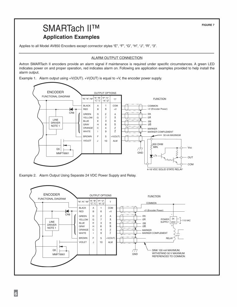
Alarm*Open collector, normally off, goes low on alarm,
sink 100mA max, 50VDC max
LED Green=power on, Red=Alarm
MarkerOne per revolution. Pulse width
approximately 1/128 of a revolution
*Alarm not available on connector option “G” (NorthstarTM compatible pinout)
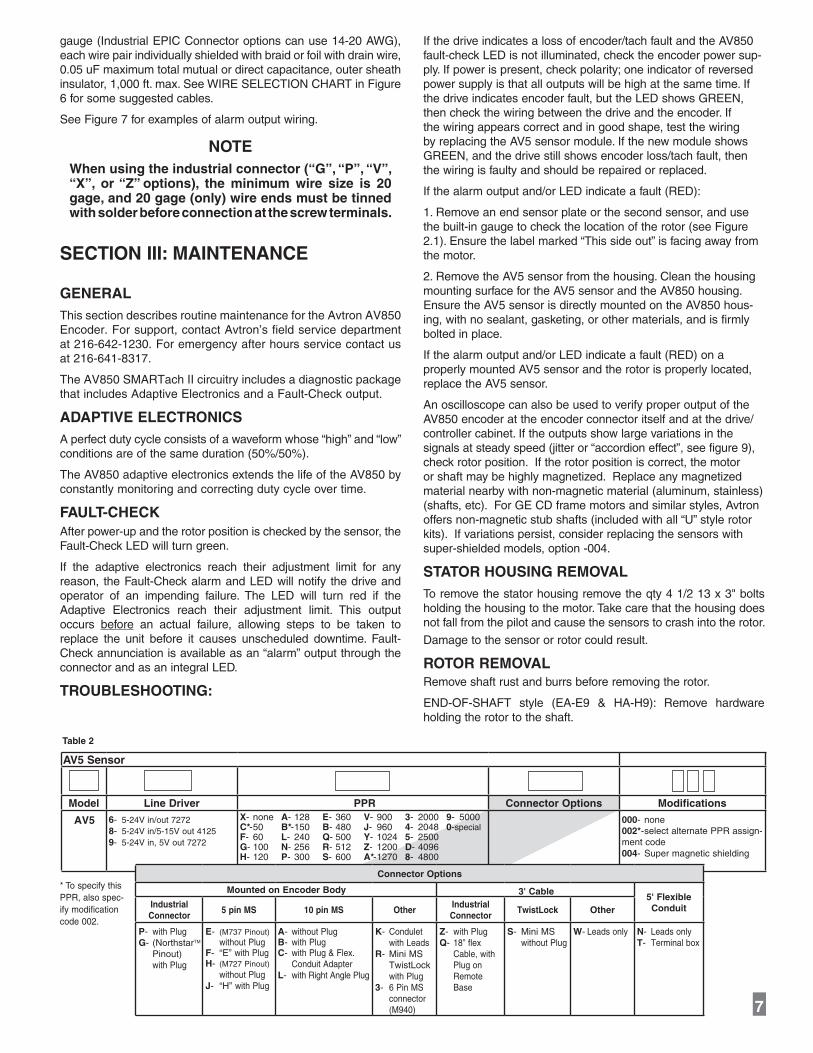
AV5 Sensor
Model Line Driver PPR Connector Options Modifications
AV5 6- 5-24V in/out 72728- 5-24V in/5-15V out 41259- 5-24V in, 5V out 7272
000- none002*- select alternate PPR assign-ment code 004- Super magnetic shielding
X- noneC*- 50F- 60G- 100H- 120
A- 128B*- 150L- 240N- 256P- 300
E- 360B- 480Q- 500R- 512S- 600
V- 900J- 960Y- 1024Z- 1200A*- 1270
3- 20004- 20485- 2500D- 40968- 4800
9- 50000-special
Table 2
ROTOR ALIGNMENT GROOVE
Figure 5
Rotormagnetic strip aligns with groove.
Connector Options
Mounted on Encoder Body 3' Cable5' Flexible ConduitIndustrial
Connector5 pin MS 10 pin MS Other
Industrial Connector
TwistLock Other
P- with PlugG- (NorthstarTM Pinout) with Plug
E- (M737 Pinout) without PlugF- “E” with PlugH- (M727 Pinout) without PlugJ- “H” with Plug
A- without PlugB- with PlugC- with Plug & Flex. Conduit AdapterL- with Right Angle Plug
K- Condulet with LeadsR- Mini MS TwistLock with Plug3- 6 Pin MS connector (M940)
Z- with PlugQ- 18” flex Cable, with Plug on Remote Base
S- Mini MS without Plug
W- Leads only N- Leads onlyT- Terminal box
** Maximum RPM may be limited for PPR > 2500 contact factory with your application.
* To specify this PPR, also spec-ify modification code 002.
4
SPECIFICATIONS
PIN OUT
COM
+V
A
A–
B
B_
Z
Z_
+V (OUT)
ALM
BLACK
RED
GREEN
YELLOW
BLUE
GRAY
ORANGE
WHITE
BROWN
VIOLET
OPTION“N”, “K”,
“W”
“N”, “K”,“W”
OPTION“A”, “B”,“C”, “L”
“A”, “B”,“C”, “L”
OPTION“P”, “V”, “Q”,
“X”, “Z”
“P”, “V”, “Q”,“X”, “Z”
OPTION“T”
OPTION“R”, “S”
“R”, “S”
A
B
D
G
E
H
C
I
F
J
1
6
2
7
3
8
4
9
5
10
COMMON
+V
ØA
ØA–
ØB
ØB_
MARKER
MARKER COMPLEMENT
RELAY +V REF*ALARM*
GROUND
(Shield)**
FUNCTION
FOR DIFFERENTIAL APPLICATIONS
F
D
A
H
B
J
C
K
NC
NC
E 10NCNCNC
E
1
6
2
7
3
8
4
9
NC*
NC*
OPTION“G”
(Shield)**NC 10NCNCNC
+V (Encoder Power)
ØB
ØA
COMMON
MARKER
RELAY +V REF*ALARM*
GROUND
FUNCTION
FOR SINGLE ENDED APPLICATIONSPIN OUT
+V
B
A
COM
Z
+V (OUT)
ALM
RED
BLUE
GREEN
BLACK
ORANGE
BROWN
VIOLET
OPTION OPTION OPTION OPTION“T”
OPTION
B
E
D
A
C
F
J
6
3
2
1
4
5
10
D
B
A
F
C
NC
NC
B
C
E
A
D
NC
NC
OPTION“E” & “F”
6
3
2
1
4
NC*
NC*
10
E
D
A
F
NC
NC
NC
OPTION“G”
FOR SINGLE ENDED SINGLE PHASE WIRING APPLICATIONS
RED
GREEN
BLACK
A
B
C
D
E
COMMON
+V (Encoder Power)
SIGN
Z (Optional)
AL
GROUND
CABLE BELDEN 8771OR EQUIVALENT
OPTION**“H” & “J” **(M727A Replacements)
OPTION“3”
56
WIRING DIAGRAMS
TYPICAL WIRE SELECTION CHART for 18 AWG, multiple pair, individually shielded
2 PAIR 9368 6062
ALPHABELDEN
3 PAIR 9369 6063
9389
9388
6 PAIR
4 PAIR
6066
6064
* See Figure 7 page 6 for examples of alarm output wiring.
** Avtron recommends shield grounding at drive end . Shield pin does not ground the shield.
EU Declaration of Conformity
FIGURE 6
Pending
BLACK
RED
GREEN
YELLOW
BLUE
GRAY
ORANGE
WHITE
BROWN
VIOLET
OUTPUT OPTIONS
A
B
D
G
E
H
C
I
F
J
94
5
10
2
837
61
+V(OUT)
Z
Z
A
B
B
A
+V
COM
Vcc
OUT
COM
300 OHMMIN.
GND
FUNCTION
ENCODER
ØB
ØA
ØA
ØB
4-16 VDC SOLID STATE RELAY
Q5
MMFT6661
LINEDRIVERNOTE 1
CR8 {FUNCTIONAL DIAGRAM
50 mA MAXIMUM
“N”,“K”,“W” “A”,“B”,“C”,“L”
“P”,“V”, “X“,“Z” “T”
ALM
MARKERMARKER COMPLEMENT
COMMON+V (Encoder Power)
{BLACK
RED
GREEN
YELLOW
BLUE
GRAY
ORANGE
WHITE
BROWN
VIOLET
T
OUTPUT OPTIONS
A
B
D
G
E
H
C
I
F
J
94
5
10
2
837
61
ALM
+V(OUT)
Z
Z
A
B
B
A
+V
COM
MARKERMARKER COMPLEMENT
GND
FUNCTION
+V (Encoder Power)
COMMON
24
VDC
RELAY
+
-
POWERSUPPLY
115 VAC
SINK 100 mA MAXIMUM,WITHSTAND 50 V MAXIMUMREFERENCED TO COMMON
Q5
MMFT6661
ENCODERFUNCTIONAL DIAGRAM
ØB
ØA
ØA
ØB
LINEDRIVERNOTE 1
CR8
“N”,“K”,“W” “A”,“B”,“C”,“L”
“P”,“V”, “X“,“Z”
Example 2. Alarm Output Using Separate 24 VDC Power Supply and Relay.
Applies to all Model AV850 Encoders except connector styles “E”, “F”, “G”, “H”, “J”, “R”, “3”.
ALARM OUTPUT CONNECTION
Avtron SMARTach II encoders provide an alarm signal if maintenance is required under specific circumstances. A green LED indicates power on and proper operation, red indicates alarm on. Following are application examples provided to help install the alarm output.
Example 1. Alarm output using +V(OUT). +V(OUT) is equal to +V, the encoder power supply.
SMARTach II™Application Examples
FIGURE 7
6. Slide the V-ring seal onto the shaft, and ensure that it is compressed against the cover. See installation Figure 4.
(OPTIONAL) SHAFT GROUNDING KIT INSTALLATION (Rotors “FA-F9”, “GA-G9”)
Refer to separate Shaft Grounding Kit Instructions (M190-AV850)
(OPTIONAL) CHECK ROTOR POSITION 1. Remove a sensor or blank side cover plate.
2. Verify the rotor magnetic stripe is aligned with the grooves (see Figure 5).
3. Replace the sensor or side cover plate.
WIRING INSTRUCTIONS
CAUTIONRemove power before wiring.
Wiring diagrams are shown in Figure 6 and 7.
For bidirectional operation of the encoder, proper phasing of the two output channels is important. Phase A channel leads phase B channel for clockwise shaft rotation as viewed from the anti-drive or accessory end of the motor (encoder mounting end).
Wiring option “G” provides a pinout compatible with NorthstarTM
encoders, with a cable shield connection on pin 10. Note that this option does not ground the shield; Avtron still recommends grounding the shield at the drive end of the cable for all wiring options.
CORRECTIVE ACTION FOR PHASE REVERSAL1) Remove Power.2) Exchange wires on cable, either at encoder cable end or at speed controller end (but not both).
7
a) Single Ended 2 Phase Wiring (see wiring diagram) Exchange A and B at the use end of the wires. b) Differential 2 Phase Wiring (see wiring diagram) Exchange either A with A– in the phase A pair OR B with B– in the phase B pair but NOT both.3) Apply power and verify encoder feedback is correct.
Interconnecting cables specified in the WIRE SELECTION CHART in Figure 6 are based on typical applications. Refer to the system drawing for specific cable requirements where applicable.
Physical properties of cable such as abrasion, temperature, tensile strength, solvents, etc., are dictated by the specific application. General electrical requirements are: stranded copper, 22 thru 16
gauge (Industrial EPIC Connector options can use 14-20 AWG), each wire pair individually shielded with braid or foil with drain wire, 0.05 uF maximum total mutual or direct capacitance, outer sheath insulator, 1,000 ft. max. See WIRE SELECTION CHART in Figure 6 for some suggested cables.
See Figure 7 for examples of alarm output wiring.
NOTEWhen using the industrial connector (“G”, “P”, “V”, “X”, or “Z” options), the minimum wire size is 20 gage, and 20 gage (only) wire ends must be tinned with solder before connection at the screw terminals.
SECTION III: MAINTENANCE
GENERALThis section describes routine maintenance for the Avtron AV850 Encoder. For support, contact Avtron’s field service department at 216-642-1230. For emergency after hours service contact us at 216-641-8317.
The AV850 SMARTach II circuitry includes a diagnostic package that includes Adaptive Electronics and a Fault-Check output.
ADAPTIVE ELECTRONICSA perfect duty cycle consists of a waveform whose “high” and “low” conditions are of the same duration (50%/50%).
The AV850 adaptive electronics extends the life of the AV850 by constantly monitoring and correcting duty cycle over time.
FAULT-CHECKAfter power-up and the rotor position is checked by the sensor, the Fault-Check LED will turn green.
If the adaptive electronics reach their adjustment limit for any reason, the Fault-Check alarm and LED will notify the drive and operator of an impending failure. The LED will turn red if the Adaptive Electronics reach their adjustment limit. This output occurs before an actual failure, allowing steps to be taken to replace the unit before it causes unscheduled downtime. Fault-Check annunciation is available as an “alarm” output through the connector and as an integral LED.
TROUBLESHOOTING:
If the drive indicates a loss of encoder/tach fault and the AV850 fault-check LED is not illuminated, check the encoder power sup-ply. If power is present, check polarity; one indicator of reversed power supply is that all outputs will be high at the same time. If the drive indicates encoder fault, but the LED shows GREEN, then check the wiring between the drive and the encoder. If the wiring appears correct and in good shape, test the wiring by replacing the AV5 sensor module. If the new module shows GREEN, and the drive still shows encoder loss/tach fault, then the wiring is faulty and should be repaired or replaced.
If the alarm output and/or LED indicate a fault (RED):
1. Remove an end sensor plate or the second sensor, and use the built-in gauge to check the location of the rotor (see Figure 2.1). Ensure the label marked “This side out” is facing away from the motor.
2. Remove the AV5 sensor from the housing. Clean the housing mounting surface for the AV5 sensor and the AV850 housing. Ensure the AV5 sensor is directly mounted on the AV850 hous-ing, with no sealant, gasketing, or other materials, and is firmly bolted in place.
If the alarm output and/or LED indicate a fault (RED) on a properly mounted AV5 sensor and the rotor is properly located, replace the AV5 sensor.
An oscilloscope can also be used to verify proper output of the AV850 encoder at the encoder connector itself and at the drive/controller cabinet. If the outputs show large variations in the signals at steady speed (jitter or “accordion effect”, see figure 9), check rotor position. If the rotor position is correct, the motor or shaft may be highly magnetized. Replace any magnetized material nearby with non-magnetic material (aluminum, stainless) (shafts, etc). For GE CD frame motors and similar styles, Avtron offers non-magnetic stub shafts (included with all “U” style rotor kits). If variations persist, consider replacing the sensors with super-shielded models, option -004.
STATOR HOUSING REMOVALTo remove the stator housing remove the qty 4 1/2 13 x 3" bolts holding the housing to the motor. Take care that the housing does not fall from the pilot and cause the sensors to crash into the rotor.
Damage to the sensor or rotor could result.
ROTOR REMOVAL Remove shaft rust and burrs before removing the rotor.
END-OF-SHAFT style (EA-E9 & HA-H9): Remove hardware holding the rotor to the shaft.
ELECTRICALA. Operating Power (Vin) 1. Volts ............................ 5-24 VDC in 2. Current ....................... 100mA, each output, no loadB. Output Format 1. 2O// & Comp ................ A,A–, B,B– (differential line driver) 2. Marker: ....................... 1/Rev Z, Z–
C. Signal Type ..................... Incremental, Square Wave, 50 +/-10% ................................... Duty Cycle.D. Direction Sensing ........... O/ A leads O/ B for CW rotation as ................................... viewed from the back of the tach ................................... looking at the non-drive end of ................................... the motor.E. Transition Sep. ................ 15% minimumF. Frequency Range ........... 0 to 165,000 HzG. PPR ................................ 8-5000
H. Line Driver Specs: .......... See table
I. Connectors: .................... See connector options on page 1
K. INTEGRAL LED INDICATOR ................................... GREEN - Power On, Unit Ok ................................... RED - Alarm On
MECHANICALA. Rotor Inertia ................... 0.17-0.36 Oz. In. Sec.2
B. Acceleration .................... 5000 RPM/Sec. Max.C. Speed: ............................ 6000** RPM Max.D. Weight: ........................... 9 lbs. [ 4 kg.]E. Sensor to Rotor Air Gap (nominal): ............... 0.050" [1.27mm]Tolerance: ........................... +0.015"/-0.040" [+0.38/-1.02mm] F. Rotor Axial Tolerance ..... +/-0.100" [+/-2.54mm]
ENVIRONMENTALSolid cast aluminum stator and rotorFully potted electronics, protected against oil and water sprayV-Ring seals provided on through shaft coversOperating Temperature:.......-40 to 100°C, 0-100% condensing humidity
LINE DRIVER OPTIONS
Electrical Specifications 6 8 9 Units
Input Voltage 5-24 5-24 5-24 VDC
Nom Output Voltage 5-24 5-15 5 VDC
Line Driver 7272 4125 7272
Output Resistance Typ 13 3 13 ohms
Maximum Peak Current 1500 3000 1500 mA
Maximum Average Current
120 350 120 mA
Voh Typ VIN-1 VIN-1, max 15V out VIN-1 VDC
Vol Typ 0.5 0.4 0.5 VDC
Cable Drive Capacity1000’ @ 5V 500’ @ 12V200’ @ 24V
1000’ 1000’ feet
Protection
Reverse Voltage
yes yes yes
Short Circuit
yes yes yes
Transient yes yes yes
Alarm
+V(out)Output voltage equal to input voltage.
See Figure 2-5 for application.
Alarm*Open collector, normally off, goes low on alarm,
sink 100mA max, 50VDC max
LED Green=power on, Red=Alarm
MarkerOne per revolution. Pulse width
approximately 1/128 of a revolution
*Alarm not available on connector option “G” (NorthstarTM compatible pinout)
AV5 Sensor
Model Line Driver PPR Connector Options Modifications
AV5 6- 5-24V in/out 72728- 5-24V in/5-15V out 41259- 5-24V in, 5V out 7272
000- none002*- select alternate PPR assign-ment code 004- Super magnetic shielding
X- noneC*- 50F- 60G- 100H- 120
A- 128B*- 150L- 240N- 256P- 300
E- 360B- 480Q- 500R- 512S- 600
V- 900J- 960Y- 1024Z- 1200A*- 1270
3- 20004- 20485- 2500D- 40968- 4800
9- 50000-special
Table 2
ROTOR ALIGNMENT GROOVE
Figure 5
Rotormagnetic strip aligns with groove.
Connector Options
Mounted on Encoder Body 3' Cable5' Flexible ConduitIndustrial
Connector5 pin MS 10 pin MS Other
Industrial Connector
TwistLock Other
P- with PlugG- (NorthstarTM Pinout) with Plug
E- (M737 Pinout) without PlugF- “E” with PlugH- (M727 Pinout) without PlugJ- “H” with Plug
A- without PlugB- with PlugC- with Plug & Flex. Conduit AdapterL- with Right Angle Plug
K- Condulet with LeadsR- Mini MS TwistLock with Plug3- 6 Pin MS connector (M940)
Z- with PlugQ- 18” flex Cable, with Plug on Remote Base
S- Mini MS without Plug
W- Leads only N- Leads onlyT- Terminal box
** Maximum RPM may be limited for PPR > 2500 contact factory with your application.
* To specify this PPR, also spec-ify modification code 002.
4
SPECIFICATIONS
the V-ring seal an additional 0.09" [2.29mm] toward motor. Verify the V-ring seal is clear of the motor bearings and housing. V-ring seal compression should be between 0.03" and 0.09" [0.75mm-2.29mm] in final position when plate is reapplied.
5. Remove the double-stick tape protection. Align the bolt holes.
6. Stick the inner cover plate in place.
7. Mount rotor per instructions below, but increase axial position from motor to rotor to 0.620" [15.75mm] (from 0.584") to accommodate the inner seal plate thickness. See Figure 3.
8. Mount remainder of AV850 per instructions below.
SHIELD INSTALLATIONFor top performance on older motors with magnetized shafts and frames install the AV850 shield. The AV850 also has built-in shields attached to the housing of every unit. For additional protection, consider the -004 option for extra sensor shielding.
1. Remove the double-stick tape protection.
2. Align the bolt holes and edges with the motor C-face.
3. Stick the shield in place on the motor C-face or on top of any inboard seal plate.
4. Install rotor as usual, but gage location from the shield. See Figure 3.
The outer edge of the rotor may be damaged by scratches, severe blows, and strong magnetic fields.
ROTOR INSTALLATIONUse the dial indicator gauge to ensure motor shaft runout (TIR) does not exceed (0.004") [0.10mm]. Apply anti-seize compound to the shaft.
UNIVERSAL END-OF-SHAFT APPLICATIONS: (Rotors GF-G9, UF-U9, QF-Q9) See Table 2 for part numbers.
1. Verify the shaft projection from the C-face of the motor is 0.400".
2. GE CD180-320 style kits (-UF) require a roll pin (included) to be inserted into the shaft hole before installation of the stub shaft adapter.
2a. Install the shaft adapter on the motor using the bolts, threadlocker and washers provided.
3. Verify the stub shaft runout/wobble is less than 0.004" TIR. (0.001" is ideal). Use a dead blow hammer or shims (provided) to true the shaft as needed.
4. Slide the rotor onto the stub shaft. The space between the mounting face and the magnetic strip of the rotor must be set to 0.584", as shown in Figure 2. Use Avtron gauges (A25355 or A35226) or use housing alignment grooves as shown in Figure 5 to verify position. Note: if optional inboard seal plate and/or shield is used, gage the rotor location from the shield/seal plate(s). Ensure the rotor label marked “this side out” is facing away from the motor.
4a. For rotors UN, UP, and UQ ensure the counter bored holes on the motor side of the rotor line up with the bolt heads used to mount the adapter. This will permit proper rotor axial positioning.
5. Turn the cam screws of the rotor in the directions shown on the rotor to engage the cams. Tighten to 9-10 ft lbs (12.2-13.5 n-m). Total cam screw rotation will be less than one turn.
END-OF-SHAFT APPLICA TIONS (Rotors EF-E9, HF-H9) See Table 2 for part numbers:
1. Verify that the shaft projection from the C-face of the motor is 0.400" [10.2mm]. Apply antiseize to the shaft.
1a. GE CD180-320 style kits (-EF) require a roll pin (included) . Install the pin in the rotor first, then position the rotor on the shaft. Lightly tap into place.
2. Apply threadlocker to the bolt(s); use the supplied washer(s) and tighten.
THROUGH SHAFT APPLI CA TIONS (Rotors TA-T9, CA-C9, MF-MZ) See Table 3 for part numbers:
1. The through-shaft must project at least 1.2" [30.48mm] from the accessory mounting face. If it is greater than 2" [50.80mm] long, use the outboard through-shaft cover, detailed in Figure 4.
2. Slide the rotor on the shaft (option “B” or “T”), ensuring the rotor label “this side out” is away from the motor. The space between the mounting face and the rotor must be set to 0.584" [14.83mm], as shown in Figure 2. Use Avtron gauges (A35226 or A25355) or housing alignment grooves as shown in Figure 5 to verify position. (Note: if optional inboard seal or shield plate is used, gage the rotor location from the seal shield plates. See Figure 3.) If using a set screw rotor (TA-T6), apply threadlocker to the set screws (2) and tighten to 25 in-lbs. If using a cam screw rotor (CA-C3), threadlocker is pre applied.
3. Turn the cam screws of the rotor in the directions shown on the rotor to engage the cams. Tighten to 9-10 ft lbs (12.3- 13.5 n-m). Total cam screw rotation will be less than one turn.
STATOR HOUSING IN STALL ATION
NOTE:If additional magnetic shielding (option 004) has been added to the sensors, be sure to remove the sensors before installing the stator housing.
The stator housing is retained to the motor using four, 1/2-13 x 3" bolts and spring type lock washers (supplied). If the stator is to be sandwich mounted between an accessory such as a brake and the motor, select the bolt length accordingly. Apply antiseize compound to the perimeter of the AV850 where it will contact the motor C-face. Carefully move the stator housing into position, avoiding contact with the rotor. DO NOT FORCE the housing into place. Install the four mounting bolts (torque 30 to 35 foot pounds) [47.5-40.6 n-m].
CAUTIONDO NOT use silicone sealants or caulk of any kind on the motor or encoder face; these can cause misalignment or sensor scraping damage. Do apply antiseize compound (copper) to the encoder face to assist in easy removal. The AV850 electronics are fully sealed; water may enter and leave the rotor area as needed. Remove the bottom pipe plug in the housing if frequent moisture buildup is expected.
(OPTIONAL) OUTBOARD SEAL PLATE KIT INSTALLATION.
For applications requiring shafts to pass completely through the AV850, Avtron offers an outboard through-shaft seal plate kit with V-ring seal. See Table 4 for part numbers and Figure 4.
1. Install the encoder rotor as shown above.
2. Remove the existing cover of the encoder. Retain the screws and washers.
3. Mount the AV850 stator housing as shown above.
4. Install new through-shaft cover using the (4) #10-24 screws and washers from step 2.
5. Apply silicone lubricant or medium grade machine oil (20 weight) to the outboard side of the cover where the V-ring seal will contact it. 38
Imperial (US) Sizes
Shaft Bore
Inboard Covers
Flat Thru-ShaftCover
MagneticShieldSeal ONLY Seal ONLY
-AN
-NA--NA--NA-
-NA--NA--NA-
-NA--NA-
A35355
A35355A35355A35355
A35355A35355A35355A35355A35355A35355A35355A35355A35355
A35355A35355
A35355A35355A35355--AN-8091742-30243A43903BAC-41513BACAT-51903BAT"057.0
4181741-11262A4181741-30243A51513B*BCBT-51903BBT"526.0-AN--AN-1391743-30243ACC-41513BCCCT-51903BCT"578.0
0091742-11262A0091744-30243AEC-41513BECET-51903BET"000.13781743-11262A3781745-30243AFC-41513BFCFT-51903BFT"521.1
4881744-11262A4881747-30243AHC-41513BHCHT-51903BHT"573.11091745-11262A1091748-30243AJC-41513BJCJT-51903BJT"526.1
-AN--AN-20917401-30243AKC-41513BKCKT-51903BKT"057.12091746-11262A20917411-30243ALC-41513BLCLT-51903BLT"578.16881747-11262A68817421-30243AMC
-41513BMCMT-51903BMT"000.2
3091748-11262A30917431-30243ANC-41513BNCNT-51903BNT"521.240917421-11262A40917451-30243APC-41513BPCPT-51903BPT"573.23091748-11262A30917441-30243AQC-41513BQCQT-51903BQT"052.25091749-11262A50917461-30243ARC-41513BRCRT-51903BRT"005.2
-AN--AN-50917452-30243ATC-41513BTCTT-51903BTT"526.2-AN--AN-70917491-30243AWC-41513BWCWT-51903BWT"052.3-AN--AN-60917402-30243AYC-41513BYCYT-51903B YT"573.3-AN--AN-60917412-30243AZC-41513BZCZT-51903BZT"124.3
58817401-11262A58817471-30243A2C-41513B2C2T-51903B2T"578.201917411-11262A01917422-30243A3C-41513B3C3T-51903B3T"005.3
-AN--AN-34917432-30243A-AN--AN-4T-51903B4T"578.3-AN--AN--AN-42-30243A-AN--AN-6T-51903B6T"005.4
Metric Sizes-AN--AN-9391746-30243A43903B-AN--AN-MF-51903BFMmm03-AN--AN-1091749-30243A-AN--AN--51903BJMmm24-AN--AN-40917451-30243A-AN--AN--51903BPMmm06-AN--AN-70917481-30243A-AN--AN--51903BYMmm08-AN--AN-70917481-30243A-AN--AN--51903BZM
JMPMYMZMmm08
Outboard Covers
Set Screw
Cam Screw
Rotor PartRotor PartRotor Code
Rotor Code
Through Shaft RotorsSPARE THROUGH SHAFT ROTORS AND COVERS
Set Screw
Cam Screw
95mm
3.625"
3.750"
4.000"
TD
TG B30915-TG
B30915-T1T1
B30915-TD
M4 B30915-T4
-AN-
-AN- -AN- -AN- -AN- -AN- -AN- -AN-
-AN-
-AN- -AN- -NA- -NA- -AN- -AN-
-AN-
-AN- -AN- -AN- -AN- -AN- -AN-
-AN--AN--AN--AN--AN--AN-
A35355
Table 4
SPARE END OF SHAFT ROTORS
Motor Specific Style Universal Style
Motor Frame Code RotorShaft
Grounding KitCode Rotor Shaft Adapter**
Shaft Ground Kit
Magnetic Shield
Universal rotor only* (no stub shaft)
-NA- -NA- -NA- CB* B31515 none -NA- -NA-
CD 180-32x EF/HF B30916-EF A34137 QF/UF/GF B31515 B31516 A34396 A35355
CD36x EN/HN B30916-EN A34138 QN/UN/GN B31515 B31517 A34397 A35355
CD4xx EP/HP B30916-EP A34139 QP/UP/GP B31515 B31518 A34397 A35355
CD444/CD505E EQ/HQ B30916-EQ -NA- QQ/UQ/GQ B31515 B31631 A34397 A35355
CD43xx, 44xx, 54xx, 64xx, 65xx
-NA- -NA- QV/UV/GV B31515 B31676 A34397 A35355
CD45xx, 75xx, 76xx -NA- -NA- QW/UW/GW B31515 B31676 A34397 A35355
CD46xx, 47xx, 85xx, 86xx -NA- -NA- QY/UY/GY B31515 B31677 A34397 A35355
CD68x -NA- -NA- QZ/UZ/GZ B31515 B31678 A34397 A35355
CD5xx (excluding CD505) E2/H2 B30916-E2 A34140 Q2/U2/G2 B31515 B31519 A34397 A35355
E9- CD60xx, 61xx, 62xx, 67xx, 68xx, 69xx
E9/H9 B31092 A34141 Q9/U9/G9 B31515 B31520 A34397 -NA-
All except CD505 and CD680
-NA- -NA- -NA- UU B31515B31516, B31517, B31518, B31637, B31676, B31677
-NA- -NA-
** Shaft adapter part numbers for rotor style “Q” (stacked encoders) is the same as above but with a “-1” suffix.
* Note Universal rotor (CB) is a 5/8" thru-shaft cam screw style rotor. Universal style kits (GF-G9, QF-Q9, UF-U9) add the required stub shaft to fit the rotor to GE CD frame motors.
Table 3
FACE
SETSCREW
HUB
MOUNTINGACCESSORY
SEAL PLATEAND SHIELD
MOTOR
V-RINGSEAL
MOTORSHAFT
HOUSINGSTATOR
0.584 [14.8mm] from seal plateand shield (+/-0.100" [+/-2.5mm])
3/16" Hex Wrench (cam screw rotors only) 9/16" Wrench (end-of-shaft rotors only)
Optional: A35226 Gauge or A25355 M285/AV850 Rotor Gauge Block Inboard Through-Shaft Seal Plate Outboard Through-Shaft Seal Plate Kit Silicone Lubricant or 20 Weight Machine OilDead Blow Hammer Large Frame Adapter Kit (Modification “700”) AV850 Shield Kit (A35355)
(OPTIONAL) LARGE MOTOR STATOR ADAPTER INSTAL-LATION (Modification “700”)
For large frame GE CD motors Avtron offers a frame adapter to add an 8.5" C-face to the motor. To install the flange adapter:
1. Remove all existing adapters on the non-drive end of the motor.
2. Clean the motor flange.
3. Using the supplied hardware, bolt the flange adapter in place (see Figure 1).
4. Apply anti-seize to the frame adapter C-face flange.
(OPTIONAL) INBOARD SEAL PLATE INSTALLATION (Cover Plate “B” & “N”):
For installations where the AV850 will be mounted to an open frame flange adapter, or other installation where the inner surface of the AV850 will not form a seal with the rear end bell of the motor, Avtron offers inboard, through-shaft seal plate kits. These kits include a cover plate and seal. See Table 3 for part numbers. To install the inboard through-shaft seal plate kit:
1. Verify all components fit the motor shaft (rotor, V-ring seal, and seal plate.
2. Slide V-ring seal onto motor shaft.
3. Apply a light coating of silicone lubricant or medium grade machine oil to the outward face of the seal.
4. Use the seal plate to push the seal on the shaft; stop when the seal plate contacts the motor face. Remove the seal plate and push
The AV5 removable sensor assembly has a diagnostic package that includes Adaptive Electronics and a Fault-Check output. With this package, the SMARTach II can maintain itself, and let you know if there is a problem before the problem causes unscheduled downtime.
SECTION II: INSTALLATIONGENERALThe motor must comply with NEMA MG1 for dimensions, face runout, and shaft runout. Axial float or endplay must be less than +/-0.100" inch.
CAUTIONDo not strike the encoder or rotor at any time. Damage will result and the warranty will be void. At installation, clean and remove paint and burrs from motor shaft and mounting face. Apply anti-seize compound (supplied) to each except cam screw rotors.
INSTALLATION HARDWAREInstallation hardware required is attached to each assembly.
Equipment needed for installationSupplied:
AV850 Encoder 1. Washer, Spring Lock 1/2 (4) 2. Hex Hd. Cap Screw 1/2-13 x 3.00 (4)
Rotor 1. Rotor Installation Hardware Kit 2. Anti-Seize Compound (copper) 3. Thread Locker (blue)
Not Supplied:3/4" Wrench Phillips Screwdriver7/16" Nut Driver Dial IndicatorVernier Caliper 3/32" Hex Wrench (T-Handle style) (thru shaft rotors only)
9
MOTOR
V-RINGSEAL
MOTORSHAFT
0.584 [14.8mm] from seal plate and shield. (+/-0.100" [+/-2.5mm])
OPTIONAL OUTBOARD SEAL PLATE
MOTOR
LARGE FRAMEADAPTER
STATORHOUSING
MOTOR SHAFT
CAM SCREWUNIVERSALROTOR
SHIELD PLATE
SHAFT ADAPTER
0.584 [14.8mm] fromshield and seal plate
FIGURE 1
SET SCREW STYLE “TA-T9,
MA-M9”
CAM SCREW STYLE “CA-C9,
GA-G9”
ACCESSORY MOUNTING FACE
0.584 +/-0.100" [14.8mm +/-2.5mm]
MOTOR
OPTIONAL INBOARD SHIELD AND/OR
SEAL PLATE
FIGURE 2 FIGURE 3
2
0.19 (4.83)
8.50158.5035
DIA
(215.938)(215.989)
DIA
DRAIN PLUG 1/8 - 27 N.P.T.
NOTE: If the pulse generator will beexposed to water spray, the bottom1/8" pipe plug should be removed.
2.54(64.52)
1.29(32.8)
0.24(6.10)
5FT (1524.0) MIN
45∞
0.562 (14.275) DIA - 4 HOLESEQUALLY SPACED ON A7.250 (184.150) DIA.
4.38(111.25)
9.00 (228.60) DIA
LED Indicator
STANDARD:1/2-14 NPT
COVER PLATESINGLE OUTPUTONLY
OPTION “P”, “G”PLUG-IN INDUSTRIAL CONNECTOR
ALTERNATES SHOWN BELOW
OPTION “N”FLEXIBLE WATER-PROOF CONDUIT
RIGHTMODULELEFT
MODULE
0.53 (13.5)
3.83 (97.3) 4.66 (118.4)
OPTION "R"
OPTION "3"6 PIN MS
CONNECTOR (M940)
OPTION "K"
2.80 (71.1)
3.06(11.7)
1.53(38.9)
OPTION "A" BULKHEAD CONNECTOR ONLY
OPTION "B"WITH MATING PLUG & CABLE GROMMET
1.97(50.0) 3.67 (93.2)
Assembled
0.53(13.5)
1.66(42.2)
OPTION "C"
3.25(82.6)
OPTION "E" & "H" BULKHEAD CONNECTOR ONLY
OPTION "F" & "J"WITH MATING PLUG
0.53(13.5)
1.42(36.0)
3.08 (78.2)Assembled
1.85(47.0)
1.42(36.0)
OPTION "L"
0.53(13.5)
2.09(53.0)
1.97(50.0)
3.87 (98.3)
OPTION "S" 0.53(13.5)
36.50 (927.0) MIN
OPTION "W"0.53
(13.5)
36.50 (927.0) MIN
OPTION "T"
Terminal Block
2.00(50.8)
4.31(109.5)
1.16(29.3)
1.16(29.3)
0.312 (7.92)4 Holes
Box is 3.12 (79.25) Deep
0.53(13.5)
4.750 (120.6)
5.50 (140.0)
5FT (1524.0) MIN
OPTION "X" SURFACE MOUNT CONNECTOR ONLY
OPTION "Z"WITH MATING PLUG
0.53(13.5)
0.41 (10.5)
1.20(30.5)
4.31(109.5)
1.574(40.0)
2.13(54.0)
3.228 (82.0)
3.70 (94.0)
0.18(4.5)
0.217 (5.50)4 Holes
36.50 (927.0) MIN
5.641(143.3)
5.641(143.3)
1.072(27.2)
MOTOR SIDE
OPTION “TA-T9, MA-M9”SET SCREW STYLE ROTOR
5.641(143.3)
1.011(25.7)
MOTORSIDE
OPTION“CA-C9, UA-U9,
GA-G9”CAM SCREW
STYLE ROTOR
PLUG WITH CONDUIT ADAPTER
OPTION “Q”REMOTE BASE FOR BALDOR TEFC/TENV
MOTORS
18.00[457.2]
MIN
0.30[7.6]
0.81[20.6]
ADDITIONAL CONNECTOR OPTIONS
Dimensions in parenthesis are in millimeters. All dimensions are approx.
FIGURE 8
Pending
THROUGH-SHAFT and UNIVERSAL (CA-C9, TA-T9, UA-U9) styles: Loosen the set or cam screws holding the rotor to the shaft. The cam screws rotate less than one turn to disengage the shaft. Do not remove the cam screws from the rotor. The stub shaft adapter from the universal (Ux) rotors can be left in place.
Remove the rotor by hand, taking care not to damage the outer magnetized ring.
If the rotor can not be removed by hand, use a gear puller taking care not to damage the outer magnetized ring. DO NOT APPLY HEAT TO THE ROTOR.
RENEWAL AND SPARE PARTSSee Tables 2, 3, and 4.
All trademarks (™, ®) are the property of their respective owners and are used for identification purposes only.
Cam screw rotors patented.
ROTOR MOUNTING(Through Shaft Shown)
FIGURE 4
OPTIONAL LARGE STATOR ADAPTER
FIGURE 9
VARIATION > ± 15%
PHASE A
PHASE B
An Avtron AV850 SMARTach II is equipped with one or two AV5 sensor modules. Each module has a two-phase output (A,B) 90° out of phase, with complements (A
–,B–), (A Quad B Output), and a
marker pulse with complement (Z,Z–). For applications which require
more than 2 independent outputs, AV850 encoders may be stacked through the use of shaft adapters, see Table 2 for part numbers. Two separate encoders would be purchased. For example, part numbers AV850Q_X_ _ _ _ _000 and AV850CBF_ _ _ _ _000.
Output resolution on the AV850 is determined by the sensor only. Unlike older models, any PPR’s can be mixed and matched. Selection of the rotor is based only on the shaft mounting requirements (and not PPR).
NOTESpecial option 002 selects an alternate PPR code definition. Example: A-128 PPR with option code 000. A*-1270 PPR with option code 002.
SECTION I: DESCRIPTIONGENERAL
The Avtron Model AV850 SMARTach II™ is an incremental encoder (also known as tachometer or rotary pulse generator), allowing operation down to zero RPM. It provides a specific number of electrical Pulses Per Revolution (PPR) that are proportional to a shaft’s revolution. The AV850 SMARTach II is a bearingless, couplingless, modular design, providing unequaled reliability and mechanical performance.
The AV850 fits AC and DC motors with an 8.5" C (FC / 180) Face. Both end-of-shaft and through shaft mountings are accommodated.
The AV850 Encoder consists of three or four parts: a rotor, a stator housing, and one or two removable sensor modules. No gapping, adjustment, or shimming is required!
8 9 0 1 E . P L E A S A N T VA L L E Y ROA D
I N D E P E N D E N C E , O H I O 4 4 1 3 1 - 5 5 0 8
T E L E P H O N E : ( 1 ) 2 1 6 - 6 4 2 - 1 2 3 0 • FA X : ( 1 ) 2 1 6 - 6 4 2 - 6 0 3 7
E - M A I L : t a c h s @ av t r o n . c o m • W E B : w w w. av t r o n e n c o d e r s . c o m
INDUSTRIAL AUTOMATION, INC.
EncoderManual
AV850SMARTach II™
8901 E. PLEASANT VALLEY RD., INDEPENDENCE, OH 44131, U.S.A. • (1) 216-642-1230 • FAX (1) 216-642-6037 • www.avtronencoders.com
INDUSTRIAL AUTOMATION, INC.
REV: 11-05-1010
8 1/2" FC FACE MOUNT MODULAR
* To specify this PPR, also specify modification code 002.
Spare sensors, rotors, through-shaft cover plates, and shaft grounding kits can be ordered separately. (See Tables 2, 3, and 4)
Cam screw rotors patented.
TABLE 1
AV850 PART NUMBERS AND AVAILABLE OPTIONS INCLUDING AV5 SENSORS
ModelRotor Style
Shaft Size
Inboard & Outboard Cover
Plates
Left Module Right Module Connector Options
Modifi-cationsLine Driver PPR Line Driver PPR
AV850 X- noneB- inboard, thru out- board>
F- no inboard, flat outboardN- inboard, flat out-
board>
T- no inboard, thru outboard>
X- none6- 5-24V in/out 72728- 5-24V in/ 5-15V out, 4125 hi- power9- 5-24V in, 5V out 7272
X- none6- 5-24V in/out 72728- 5-24V in/ 5-15V out, 4125 hi- power9- 5-24V in, 5V out 7272
000- none002*- select alter-nate PPR assign-ment code 003- Include ana-log signal con-verter (K661) 004- Super sen-sor shielding 700- Large Motor Stator Adapter+
X- noneC*- 50F- 60G- 100H- 120A- 128B*- 150L- 240N- 256P- 300E- 360
B- 480Q- 500R- 512S- 600V- 900J- 960Y- 1024Z- 1200A*- 12703- 20004- 2048
5- 2500D- 40968- 48009- 50000-special
X- noneC*- 50F- 60G- 100H- 120A- 128B*- 150L- 240N- 256P- 300E- 360
B- 480Q- 500R- 512S- 600V- 900J- 960Y- 1024Z- 1200A*- 12703- 20004- 2048
5- 2500D- 40968- 48009- 50000-special
SMARTach II™ is a trademark of Avtron Industrial Automation, Inc.Features and specifications subject to change without notice.
Avtron standard warranty applies. All dimensions are in inches (mm).
0.19 (4.83)
8.50158.5035
DIA
(215.938)(215.989)
DIA
DRAIN PLUG 1/8 - 27 N.P.T.
NOTE: If the pulse generator will beexposed to water spray, the bottom1/8" pipe plug should be removed.
2.54(64.52)
1.29(32.8)
0.24(6.10)
5FT (1524.0) MIN
45∞
0.562 (14.275) DIA - 4 HOLESEQUALLY SPACED ON A7.250 (184.150) DIA.
4.38(111.25)
9.00 (228.60) DIA
LED Indicator
STANDARD:1/2-14 NPT
COVER PLATESINGLE OUTPUTONLY
OPTION “P”, “G”PLUG-IN INDUSTRIAL CONNECTOR
ALTERNATES SHOWN BELOW
OPTION “N”FLEXIBLE WATER-PROOF CONDUIT
RIGHTMODULELEFT
MODULE
0.53 (13.5)
3.83 (97.3) 4.66 (118.4)
OPTION "R"
OPTION "3"6 PIN MS
CONNECTOR (M940)
OPTION "K"
2.80 (71.1)
3.06(11.7)
1.53(38.9)
OPTION "A" BULKHEAD CONNECTOR ONLY
OPTION "B"WITH MATING PLUG & CABLE GROMMET
1.97(50.0) 3.67 (93.2)
Assembled
0.53(13.5)
1.66(42.2)
OPTION "C"
3.25(82.6)
OPTION "E" & "H" BULKHEAD CONNECTOR ONLY
OPTION "F" & "J"WITH MATING PLUG
0.53(13.5)
1.42(36.0)
3.08 (78.2)Assembled
1.85(47.0)
1.42(36.0)
OPTION "L"
0.53(13.5)
2.09(53.0)
1.97(50.0)
3.87 (98.3)
OPTION "S" 0.53(13.5)
36.50 (927.0) MIN
OPTION "W"0.53
(13.5)
36.50 (927.0) MIN
OPTION "T"
Terminal Block
2.00(50.8)
4.31(109.5)
1.16(29.3)
1.16(29.3)
0.312 (7.92)4 Holes
Box is 3.12 (79.25) Deep
0.53(13.5)
4.750 (120.6)
5.50 (140.0)
5FT (1524.0) MIN
OPTION "X" SURFACE MOUNT CONNECTOR ONLY
OPTION "Z"WITH MATING PLUG
0.53(13.5)
0.41 (10.5)
1.20(30.5)
4.31(109.5)
1.574(40.0)
2.13(54.0)
3.228 (82.0)
3.70 (94.0)
0.18(4.5)
0.217 (5.50)4 Holes
36.50 (927.0) MIN
5.641(143.3)
5.641(143.3)
1.072(27.2)
MOTOR SIDE
OPTION “TA-T9, MA-M9”SET SCREW STYLE ROTOR
5.641(143.3)
1.011(25.7)
MOTORSIDE
OPTION“CA-C9, UA-U9,
GA-G9”CAM SCREW
STYLE ROTOR
PLUG WITH CONDUIT ADAPTER
OPTION “Q”REMOTE BASE FOR BALDOR TEFC/TENV
MOTORS
18.00[457.2]
MIN
0.30[7.6]
0.81[20.6]
OUTLINE DIMENSIONS AND OPTION DETAILS For additional wiring options see Figure 8.
FIGURE 10
Rotor Style Shaft Size
T- Thru Shaft (Inch)C- Thru Shaft, Cam Screw (Inch)
M- Thru Shaft (mm)
E- End of ShaftH- End of Shaft for Grounding Kit
U- Universal with End of ShaftG- Universal with Grounding KitQ- EOS Adapter for Stacked Encoders
X- no rotor X- no rotor
A- 0.750B- 0.625C- 0.875
E- 1.000F- 1.125H- 1.375
J- 1.625K- 1.750L- 1.875
M- 2.000N- 2.125P- 2.375
Q- 2.250R- 2.500T- 2.625
W- 3.250Y- 3.375Z- 3.421
2- 2.8753- 3.500D- 3.625•
G- 3.750•4- 3.875•1- 4.000
6- 4.500•
F- 30mmJ- 42mm
P- 60mmY- 80mm (1)
Z- 80mm (2)4- 95mm
F- 1.125 GE CD180-320N- 2.125 GE CD360
P- 2.375 GE CD400Q- 2.250 GE CD444/505E
2- 2.875 GE CD500 9- GE CD6000, 6100, 6200, 6700, 6800, & 6900
1) For Shaft DIA 80 -.030/-.047mm (f6)
2) For Shaft DIA 80 +.0/-.030mm (h7)
Connector Options
Mounted on Encoder Body 3' Cable5' Flexible ConduitIndustrial
Connector5 pin MS 10 pin MS Other
Industrial Connector
TwistLock Other
P- with PlugG- (NorthstarTM Pinout) with Plug
E- (M737 Pinout) without PlugF- “E” with PlugH- (M727 Pinout) without PlugJ- “H” with Plug
A- without PlugB- with PlugC- with Plug & Flex. Conduit AdapterL- with Right Angle Plug
K- Condulet with LeadsR- Mini MS TwistLock with Plug3- 6 Pin MS connector (M940)
Z- with PlugQ- 18” flex Cable, with Plug on Remote Base
S- Mini MS without Plug
W- Leads only N- Leads onlyT- Terminal box
+ Large motor stator adapter required if not previously installed. > N/A for End of Shaft rotor styles. • Rotor Style “T” only.
F- 1.125 GE CD180-320N- 2.125 GE CD360P- 2.375 GE CD4002- 2.875 GE CD500R- GE CD507, 509
9- GE CD6000, 6100, 6200, 6700, 6800, & 6900V- GE CD4300, 4400, 5400,6400 & 6500+
W- GE CD4500, 7500, 7600+
Y- GE CD4600, 4700, 8500, & 8600+
Z- GE CD680+
4- ABB 95mm
U- Universal (Includes 1 Rotor and Shaft adapters for all motors except Q, R, Z & 4)Q- GE CD444/505E+


![Encoder Instructions - Nidec Avtron€¦ · fit. Ensure a minimum of 1/8" [2mm] between encoder and mounting surface. DO NOT FORCE. Encoder should slide on easily. If the encoder](https://img.pdfslide.net/doc/110x75/5ead89324fac01730a328175/encoder-instructions-nidec-fit-ensure-a-minimum-of-18-2mm-between-encoder.jpg)

![Encoder Instructions - Nidec-Avtron · 5/8/2014 · NEMA 56C FACE MOUNTING INSTRUCTIONS 1) Apply anti-seize compound [copper], included, to inner circumference of coupling (both](https://img.pdfslide.net/doc/110x75/5f7ec57f4569d2006b191b14/encoder-instructions-nidec-582014-nema-56c-face-mounting-instructions-1.jpg)